installation instructions keyless start...
TRANSCRIPT

INSTALLATION INSTRUCTIONS KEYLESS START SYSTEM
SYSTEM OVERVIEWThe KEYLESS START SYSTEM supplements a standard automotive ignition switch with a radio controlled secure passive start system. The use of a security card within 3 feet of the System Far Reader antenna, the driver is able to control the ACC, IGN, and STR functions by use of an illuminated pushbutton.
The system is designed to be wired in parallel to the existing ignition switch.
The switching functions of the ignition switch, which in a standard automotive system are used to switch battery power to accessory, ignition, and starter circuits, are replaced by 3 relays controlled by the KEYLESS START SYSTEM. The individual relays are used to provide the system power to the accessory, ignition, and starter circuits.
CONTENTS:
NEAR Reader Control Module Gray and Black headers(1) Illuminated Blue LED Push Button and wire assembly
FLAMING RIVER INDUSTRIES, INC 800 POERTNER DRIVE BEREA, OHIO 44017 800.648.8022©2009 FLAMING RIVER INDUSTRIES, INC. ALL RIGHTS RESERVED.
INSTALLATION - WIRING OVERVIEW
Instruction sheet Security card (Ignitor Key) 2 are provided
Main wire harness with black, grey, brown and green Deutsch sockets, wired to antenna modules
Note: Not all the harness positions are filled depending on model number
FAR Reader Antenna
Near Reader Antenna
FAR Reader Control Module Green and Brown headers (Note: UHF Antenna attached)
3 Relay Bank with wiring assembly
PART NUMBER FR60001
Before beginning the installation, please review the most recent instructions at:http://aftermarket.strattec.com. For questions concerning installation or performance, please call 1-800-648-8022.
Revised 3/25/09
Notes to the Installer:
1. If this is the first time you have installed the FLAMING RIVER KEYLESS START SYSTEM into a vehicle, it is recommended that the complete system should be temporarily powered up and tested outside of the vehicle prior to final installation and hardwiring into the vehicle. Either a standard 12 volt battery or a 12 VDC power supply is adequate to power the system. Fuses should be inserted as needed into the supply circuit. This bench-top testing of the system will allow the installer to become familiar with the operation of the system as well as the wiring, fusing, and load requirements.
2. Follow good automotive wiring practice for installation of the system. WARNING: The Keyless Entry System must be installed by a trained professional.
3. All wires on the switch harness, main harness, and relay harness are printed to show the connection to/from information. In addition, a wire chart is included in the instructions to show the wiring information.
4. The system uses the Deutsch DTM type connectors for connection to the main and antenna harnesses. All connectors are keyed with different unique housing configurations. The Deutsch connectors may be disconnected and reconnected as needed to route the harness and antenna wires as needed. Do not remove the individual wires from the Deutsch housing shells unless the wires are damaged and require repair.
1. The KEYLESS START SYSTEM is designed to be installed into a vehicle that utilizes a standard 4 position and 4 terminal 12 VDC automotive rated ignition switch, such as the Flaming River Ignition Switch part number FRIGN1. For reference, the 4 switch positions utilized by turning the key clockwise are:
t Accessory (Accessory terminal has 12V in this position)t Locked / Off (Key may be removed in this position, no power to any terminals in this position)t Ignition / Accessory (Ignition and Accessory terminals have 12V in this position)t Start (momentary position only, Ignition and Start terminals have 12V in this position)
STEP 1

STEP 2Position the FAR Reader Antenna - Do not permanently fix the antenna until the system is tested, as the antenna may require re-positioning to optimize the read range.
IMPORTANT – For optimal/proper system operation the FAR Reader Antenna should be mounted as follows.
1. In a location preferably close to the driver’s seat and if possible 1-2" away from any metal mounting surfaces or structures.
2. When the security card is presented it must be within three (3) feet of the FAR Reader Antenna for system operation.
NOTE: Range will be less if mounted directly on a metal surface.
3. The antenna can be mounted at any angle as needed to allow optimum performance; the mounting position is determined by trying out different positions when first testing the system.
STEP 1 (Continued)
2. Locate and identify the circuit terminals on the back of the ignition switch assembly.
ACC – Accessory Terminal
IGN – Ignition Terminal
ST – Starter Terminal
BAT – Battery Terminal
BATTERY
IGN.
STARTER
ACC
The 4 terminals are
t Battery (direct to battery circuit , always powered)t Accessory (lights, radio, other power options)t Ignition (ignition power to coil assembly)t Start (provides power to started circuit, connect to neutral safety switch or starter solenoid)
It is highly recommended that standard ignition switch and wiring should be kept intact to be used as a back-up system to the keyless start system.
The KEYLESS START SYSTEM will require access to the battery, accessory, ignition, and starter circuits.
It is also recommended that a battery kill or similar switch should be installed to allow the system to be powered down if the vehicle is stored for an extended length of time, as the system draws a small amount of power while the vehicle is turned off. The system will not be damaged by repeated power up/ power down cycles and will return to a “ready” state each time it is powered up.
3. Dedicated Circuit required for System Power:
The system requires a dedicated unswitched (constant hot) 3 amp fused circuit to power the near and Far reader control modules, and provide power to the switch LED. The dedicated unswitched (constant hot) 3 amp fused circuit should not be used for other functions, as if the power to this circuit is interrupted while the system is on and the vehicle is running, it will cause the system to lose power which will turn off relays and the associated circuits that the relays are operating.
STEP 31. Mount the push-button switch to an interior location in the vehicle. The switch has been designed to mount into a 7/8 inch diameter hole. Once the switch has been mounted, make the following wire connections.
Tan wire connects to the gray header PIN #1.
Black wire connects to the system ground.
Gray wire connects to the black header PIN #5.
Red wire connects to the 3 AMP fused un-switched positive.
2. NOTE:
The tan and gray wires are connected to the mating wires on the main wire harness. All wires are printed to show the connection information.
The red wire is connected to the unswitched dedicated constant hot 3 amp fused circuit.
The black wire is connected to the vehicle ground; preferably a common ground point should be used for all of the system ground wires.
Flaming River Part Number FRIGN1

STEP 51. Mount and position in a convenient orientation the three (3) relay pack assembly to a flat surface.
STEP 41. Mount the two (2) control modules to a flat surface using ¼ - 20 self threading screws. During installation the wiring harnesses can be removed temporarily from the control modules. The wire harness connectors (Deutsch) are keyed to insure correct orientation when reattached to the control modules.
IMPORTANT - Make sure that the Far Reader Wire Antenna located on the FAR Reader control module is not kinked or bent after installation, and should be positioned away from metal surfaces.
Far Reader Control Module
Far Reader Wire Antenna
STEP 6Relay pack wiring (please refer to the relay pack wiring diagram).
1. Operation: The system uses standard automotive rated Form C relays to switch the high current loads. A schematic of the relay is shown along with the pinouts as viewed from the wire entry side. The relay part number, pinouts, and load ratings (40 amps for the N.O. pin) are printed on the sides of the relays. The relays do not use internal diode or resistor snubbers.
FOR ALL RELAYS: Pins 30 and 86 are connected to B+, 12VDC. Pin 85 is pulled low by the system to power the coil; pin 87 is the high current output which is enabled when the coil is powered. Pin 87A is not used.
Form C Relay
Relay Pinouts
STEP 71. Wire the main harness.
a) The 2 red wires from the main harness (1 each from the near and far reader modules) should be terminated to a single wire and routed to the dedicated 3 amp constant hot fused circuit. b) The 2 black wires should be terminated to an adequate ground point. c) The blue, green and yellow wires are connected to the mating wires on the relay harness. These wires are switched by the control unit to ground in order to switch the corresponding relays. The wires should never be tied directly to 12 volts without a load, as this will short the output transistors and damage the unit.
d) The near and far reader antenna cables should be routed at this time.
2. Units built with a date code of July 2008 or later contain Deutsch DTM type disconnectable sockets in the antenna cables. For convenience, these antennas have keyed 2 and 3 pin Deutsch DTM connectors which can be disconnected and then reconnected to aid in the wire routing.
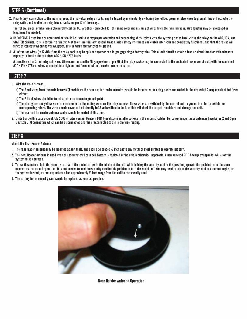
STEP 8Mount the Near Reader Antenna
1. The near reader antenna may be mounted at any angle, and should be spaced ½ inch above any metal or steel surface to operate properly.
2. The Near Reader antenna is used when the security card coin cell battery is depleted or the unit is otherwise inoperable. A non powered RFID backup transponder will allow the system to be operated.
3. To use this feature, hold the security card with the etched arrow in the middle of the coil. While holding the security card in this position, operate the pushbutton in the same manner as the normal operation. It is not needed to hold the security card in this position to turn the vehicle off. You may need to orient the security card at different angles for the system to start, as the loop antenna has approximately ½ inch range from the coil to the security card
4. The battery in the security card should be replaced as soon as possible.
STEP 6 (Continued)2. Prior to any connection to the main harness, the individual relay circuits may be tested by momentarily switching the yellow, green, or blue wires to ground, this will activate the relay coils , and enable the relay load circuits on pin 87 of the relays.
The yellow, green, or blue wires (from relay coil pin 85) are then connected to the same color and marking of wires from the main harness. Wire lengths may be shortened or lengthened as needed.
3. IMPORTANT: A test lamp or other method should be used to verify proper operation and sequencing of the relays with the system prior to hard-wiring the relays to the ACC, IGN, and STARTER circuits. It is important to run this test to ensure that any neutral transmission safety interlocks and clutch interlocks are completely functional, and that the relays will function correctly when the yellow, green, or blue wires are switched to ground.
4. All of the red wires (to 12VDC) from the relay pack may be spliced together to a larger gage single battery wire. This circuit should contain a fuse or circuit breaker with adequate capacity to handle the combined ACC / IGN / STR loads.
Alternatively, the 3 red relay coil wires (these are the smaller 18 gauge wires at pin 86 of the relay packs) may be connected to the dedicated low power circuit, with the combined ACC / IGN / STR red wires connected to a high current fused or circuit breaker protected circuit.
Near Reader Antenna Operation
STEP 9 - VERIFY KEYLESS START SYSTEM OPERATION:1. Ensure the security card is located within 3 feet of the antenna.
2. Pressing the push-button for one half second or pressing and holding will advance to the next mode every 0.5 seconds. All push-button presses will trigger the security card to blink the LED and cause the system to advance to the next state. If the card LED blinks and the system does not advance, check that the FAR reader wire antenna is not positioned directly on a metal plate or surface. If the security card is out of range, the security card LED will not blink.
a) From OFF state: This will advance unit to ACC mode. The push-button will blink slowly. b) From ACC mode: This will advance unit to IGN mode. The push-button will blink quickly indicating that the starter motor has not yet engaged. c) From IGN mode: This will advance unit to CRANK mode for as long as button is pressed. Unit will go back to IGN mode when released. The push-button will stay illuminated, indicating starter motor has been engaged.
d) From IGN mode: After a CRANK has been initiated this will advance unit to OFF state and push-button will no longer be illuminated and the sequence may be repeated.
3. Pressing the push-button for less than one half second prior to an engine CRANK will bring unit to OFF state.
NOTE: If the security card is moved out of range while the vehicle is running, the system will continue to run, and may be turned off but cannot be re-started until the security card is in range.
Security Card Battery Replacement:
The security card uses a standard CR2032 battery, the expected life of the battery is 1 year in normal operation.
To change the battery, a T6 TORX driver is needed to remove the self tapping screw. The battery must be inserted into the housing with the positive (+) side downwards.
FCC - Radio Frequency DevicesThis device complies with part 15 of the FCC Rules. Operation is subject to the following two conditions: (1) This device may not cause harmful interference, and (2) this device must accept any interference received, including interference that may cause undesired operation.
Cahiers des charges sur les normes radioélectriques du CanadaL’utilisation de ce dispositif est autorisée seulement aux deux conditions suivantes: (1) il ne doit pas produire de brouiliage, et (2) l’utilisateur du dispositif doit être prêt à accepter tout brouilage radioélectrique reçu, méme si ce brouiliage est susceptible de compromettre le fonctionnement du dispositif.
FCC WARNING: Note: Changes not expressly approved by the party
responsible for compliance could void the user’s authority to operate the equipment.
Warranty Statement
The STRATTEC Keyless Start System is guaranteed to be free from defects in material and/or workmanship and to perform as advertised when properly installed, used and maintained in accordance with the installation instructions. Failure to adhere to and/or comply with the installation instructions will void all associated warranty obligations. Should any part(s) prove defective within 6 months from date of purchase, it(they) will be replaced F.O.B. our factory without charge provided the defective part(s) is returned to our factory transportation charges prepaid.
STRATTEC Security Corporation will not be responsible for labor charges, loss or consequential damage of any kind or character caused by defected parts or charges incurred in the replacement or repair of defective parts by the Purchaser. Careless handling, including that by freight companies, and improper installation or use may void all warranties.
FCC Interference Statement (Part 15.105 (b))
This equipment has been tested and found to comply with the limits for a Class B digital device, pursuant to Part 15 of the FCC Rules. These limits are designed to provide reasonable protection against harmful interference in a residential installation. This equipment generates uses and can radiate radio frequency energy and, if not installed and used in accordance with the instructions, may cause harmful interference to radio communications. However, there is no guarantee that interference will not occur in a particular installation. If this equipment does cause harmful interference to radio or television reception, which can be determined by turning the equipment off and on, the user is encouraged to try to correct the interference by one of the following measures:
• Reorientorrelocatethereceivingantenna.
• Increasetheseparationbetweentheequipmentandreceiver.
• Connecttheequipmentintoanoutletonacircuitdifferentfromthattowhichthereceiverisconnected.
• Consultthedealeroranexperiencedradio/TVtechnicianforhelp.
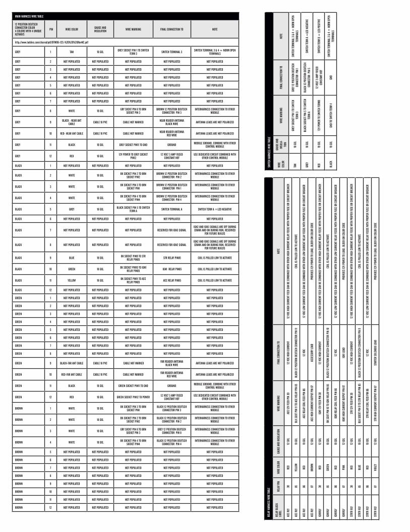
The Main Harness, Relay Harness, and Switch Harness Wire Tables are on the following pages.
RELA
Y HAR
NESS
WIR
E TA
BLE
RELA
Y BLO
CK
LABE
LRE
LAY P
INWI
RE C
OLOR
GAUG
E AN
D IN
SULA
TION
WIRE
MAR
KING
FINAL
CON
NECT
ION
TO
NOTE
ACC
RLY
30RE
D12
GXL
ACC
12V
FEED
PIN
30
12 V
DC H
IGH
CURR
ENT
12 V
DC H
IGH
CURR
ENT F
EED
CAN
BE C
OMBI
NED
WITH
OTH
ER H
IGH
CURR
ENT R
ELAY
FEED
S WI
TH P
ROPE
R FU
SE O
R CI
RCUI
T BRE
AKER
ACC
RLY
85YE
LLOW
18 G
XLBL
K SC
KT P
IN 11
TO A
CC R
ELAY
PIN
85
BLAC
K 12
POS
ITION
DEU
TSCH
CON
NECT
OR P
IN 11
COIL
IS P
ULLE
D LO
W TO
ACT
IVAT
E
ACC
RLY
86RE
D18
GXL
ACC
RELA
Y COI
L FEE
D PI
N 86
12 V
DC12
VDC
LOW
CURR
ENT F
EED
CAN
BE C
OMBI
NED
WITH
OTH
ER LO
W CU
RREN
T REL
AY FE
EDS
WITH
PRO
PER
FUSE
OR
CIRC
UIT B
REAK
ER
ACC
RLY
87BR
OWN
12 G
XLAC
C HI
GH C
URRE
NT O
UTPU
T PIN
87
ACCE
SSOR
Y LOA
DPR
OVID
ES 12
V PO
WER
TO LO
AD, O
LDER
GM
COLO
R CO
DE
IGN1
RLY
30RE
D12
GXL
IGN1
12V
FEED
PIN
30
12 V
DC H
IGH
CURR
ENT
12 V
DC H
IGH
CURR
ENT F
EED
CAN
BE C
OMBI
NED
WITH
OTH
ER H
IGH
CURR
ENT R
ELAY
FEED
S WI
TH P
ROPE
R FU
SE O
R CI
RCUI
T BRE
AKER
IGN1
RLY
85GR
EEN
18 G
XLBK
SCK
T PIN
10 TO
IGN1
REL
AY P
IN 8
5BL
ACK
12 P
OSITI
ON D
EUTS
CH C
ONNE
CTOR
PIN
10CO
IL IS
PUL
LED
LOW
TO A
CTIV
ATE
IGN1
RLY
86RE
D18
GXL
IGN1
REL
AY C
OIL F
EED
PIN
8612
VDC
12 V
DC LO
W CU
RREN
T FEE
D CA
N BE
COM
BINE
D WI
TH O
THER
LOW
CURR
ENT R
ELAY
FEED
S WI
TH P
ROPE
R FU
SE O
R CI
RCUI
T BRE
AKER
IGN1
RLY
87PI
NK12
GXL
IGN1
HIG
H CU
RREN
T OUT
PUT P
IN 8
7IG
N1 LO
ADPR
OVID
ES 12
V PO
WER
TO LO
AD, O
LDER
GM
COLO
R CO
DE
STRT
R RL
Y30
RED
12 G
XLST
R 12
V FE
ED P
IN 3
012
VDC
HIG
H CU
RREN
T12
VDC
HIG
H CU
RREN
T FEE
D CA
N BE
COM
BINE
D WI
TH O
THER
HIG
H CU
RREN
T REL
AY FE
EDS
WITH
PRO
PER
FUSE
OR
CIRC
UIT B
REAK
ER
STRT
R RL
Y85
BLUE
18 G
XLBL
K SO
CKT P
IN 9
TO S
TR R
ELAY
PIN
85
BLAC
K 12
POS
ITION
DEU
TSCH
CON
NECT
OR P
IN 9
COIL
IS P
ULLE
D LO
W TO
ACT
IVAT
E
STRT
R RL
Y86
RED
18 G
XLST
R RE
LAY C
OIL F
EED
PIN
8612
VDC
12 V
DC LO
W CU
RREN
T FEE
D CA
N BE
COM
BINE
D WI
TH O
THER
LOW
CURR
ENT R
ELAY
FEED
S WI
TH P
ROPE
R FU
SE O
R CI
RCUI
T BRE
AKER
STRT
R RL
Y87
VIOL
ET12
GXL
STR
HIGH
CUR
RENT
OUT
PUT P
IN 8
7ST
ARTE
R SO
LENO
ID LO
ADPR
OVID
ES 12
V PO
WER
TO LO
AD, O
LDER
GM
COLO
R CO
DE
SWITC
H HA
RNES
S WI
RE TA
BLE
WIRE
CO
LOR
GAUG
E AN
D IN
SULA
-TIO
NWI
RE M
ARKI
NGFIN
AL C
ONNE
CTIO
N TO
NO
TE
TAN
18 G
XLGR
EY S
OCKE
T PIN
1 TO
SWI
TCH
TERM
3GR
EY 12
POS
ITION
DEU
TSCH
CO
NNEC
TOR
PIN
1
SWITC
H TE
RMIN
AL 3
& 4
= N
ORM
OPEN
TE
RMIN
ALS
GREY
18 G
XLBL
ACK
SOCK
ET P
IN 5
TO S
WITC
H TE
RM A
BLAC
K 12
POS
ITION
DEU
TSCH
CO
NNEC
TOR
PIN
5
SWITC
H TE
RM A
=LE
D NE
GATIV
E
RED
18 G
XL12
V PO
WER
TO S
WITC
H TE
RMB
12 V
OLT 3
AMP
FUSE
D CO
NSTA
NT H
OTSW
ITCH
TERM
B =
LED
POSI
TIVE
BLAC
K18
GXL
GND
TO S
WITC
H TE
RM 4
GND
SWITC
H TE
RMIN
AL 3
& 4
= N
ORM
OPEN
TE
RMIN
ALS
MAIN HARNESS WIRE TABLE
12 POSITION DEUTSCH CONNECTOR COLOR 4 COLORS WITH 4 UNIQUE KEYWAYS
PIN WIRE COLOR GAUGE AND INSULATION WIRE MARKING FINAL CONNECTION TO NOTE
http://www.laddinc.com/shared/pdf/DTM06-12S-%20%20%20RevNC.pdf
GREY 1 TAN 18 GXL GREY SOCKET PIN 1 TO SWITCH TERM 3 SWITCH TERMINAL 3 SWITCH TERMINAL 3 & 4 = NORM OPEN
TERMINALS
GREY 2 NOT POPULATED NOT POPULATED NOT POPULATED NOT POPULATED NOT POPULATED
GREY 3 NOT POPULATED NOT POPULATED NOT POPULATED NOT POPULATED NOT POPULATED
GREY 4 NOT POPULATED NOT POPULATED NOT POPULATED NOT POPULATED NOT POPULATED
GREY 5 NOT POPULATED NOT POPULATED NOT POPULATED NOT POPULATED NOT POPULATED
GREY 6 NOT POPULATED NOT POPULATED NOT POPULATED NOT POPULATED NOT POPULATED
GREY 7 NOT POPULATED NOT POPULATED NOT POPULATED NOT POPULATED NOT POPULATED
GREY 8 WHITE 18 GXL GRY SOCKT PIN 8 TO BRN SOCKET PIN 3
BROWN 12 POSITION DEUTSCH CONNECTOR PIN 3
INTERHARNESS CONNECTION TO OTHER MODULE
GREY 9 BLACK - NEAR ANT CABLE CABLE 18 PVC CABLE NOT MARKED NEAR READER ANTENNA
BLACK WIRE ANTENNA LEADS ARE NOT POLARIZED
GREY 10 RED- NEAR ANT CABLE CABLE 18 PVC CABLE NOT MARKED NEAR READER ANTENNA RED WIRE ANTENNA LEADS ARE NOT POLARIZED
GREY 11 BLACK 18 GXL GREY SOCKET PIN11 TO GND GROUND MODULE GROUND, COMBINE WITH OTHER CONTROL MODULE
GREY 12 RED 18 GXL 12V POWER TO GREY SOCKET PIN12
12 VOLT 3 AMP FUSED CONSTANT HOT
USE DEDICATED CIRCUIT COMBINED WITH OTHER CONTROL MODULE
BLACK 1 NOT POPULATED NOT POPULATED NOT POPULATED NOT POPULATED NOT POPULATED
BLACK 2 WHITE 18 GXL BK SOCKET PIN 2 TO BRN SOCKET PIN2
BROWN 12 POSITION DEUTSCH CONNECTOR PIN 2
INTERHARNESS CONNECTION TO OTHER MODULE
BLACK 3 WHITE 18 GXL BK SOCKET PIN 3 TO BRN SOCKET PIN1
BROWN 12 POSITION DEUTSCH CONNECTOR PIN 1
INTERHARNESS CONNECTION TO OTHER MODULE
BLACK 4 WHITE 18 GXL BK SOCKET PIN 4 TO BRN SOCKET PIN4
BROWN 12 POSITION DEUTSCH CONNECTOR PIN 4
INTERHARNESS CONNECTION TO OTHER MODULE
BLACK 5 GREY 18 GXL BLACK SOCKET PIN 5 TO SWITCH TERM A SWITCH TERMINAL A SWITCH TERM A =LED NEGATIVE
BLACK 6 NOT POPULATED NOT POPULATED NOT POPULATED NOT POPULATED NOT POPULATED
BLACK 7 NOT POPULATED NOT POPULATED NOT POPULATED RESERVED FOR IGN3 SIGNALIGN2 AND IGN3 SIGNALS ARE OFF DURING CRANK AND ON DURING RUN, RESERVED
FOR FUTURE BUILDS
BLACK 8 NOT POPULATED NOT POPULATED NOT POPULATED RESERVED FOR IGN2 SIGNALIGN2 AND IGN3 SIGNALS ARE OFF DURING CRANK AND ON DURING RUN, RESERVED
FOR FUTURE BUILDS
BLACK 9 BLUE 18 GXL BK SOCKET PIN9 TO STR RELAY PIN85 STR RELAY PIN85 COIL IS PULLED LOW TO ACTIVATE
BLACK 10 GREEN 18 GXL BK SOCKET PIN10 TO IGN1 RELAY PIN85 IGN1 RELAY PIN85 COIL IS PULLED LOW TO ACTIVATE
BLACK 11 YELLOW 18 GXL BK SOCKET PIN11 TO ACC RELAY PIN85 ACC RELAY PIN85 COIL IS PULLED LOW TO ACTIVATE
BLACK 12 NOT POPULATED NOT POPULATED NOT POPULATED NOT POPULATED NOT POPULATED
GREEN 1 NOT POPULATED NOT POPULATED NOT POPULATED NOT POPULATED NOT POPULATED
GREEN 2 NOT POPULATED NOT POPULATED NOT POPULATED NOT POPULATED NOT POPULATED
GREEN 3 NOT POPULATED NOT POPULATED NOT POPULATED NOT POPULATED NOT POPULATED
GREEN 4 NOT POPULATED NOT POPULATED NOT POPULATED NOT POPULATED NOT POPULATED
GREEN 5 NOT POPULATED NOT POPULATED NOT POPULATED NOT POPULATED NOT POPULATED
GREEN 6 NOT POPULATED NOT POPULATED NOT POPULATED NOT POPULATED NOT POPULATED
GREEN 7 NOT POPULATED NOT POPULATED NOT POPULATED NOT POPULATED NOT POPULATED
GREEN 8 NOT POPULATED NOT POPULATED NOT POPULATED NOT POPULATED NOT POPULATED
GREEN 9 BLACK-FAR ANT CABLE CABLE 18 PVC CABLE NOT MARKED FAR READER ANTENNA BLACK WIRE ANTENNA LEADS ARE NOT POLARIZED
GREEN 10 RED-FAR ANT CABLE CABLE 18 PVC CABLE NOT MARKED FAR READER ANTENNA RED WIRE ANTENNA LEADS ARE NOT POLARIZED
GREEN 11 BLACK 18 GXL GREEN SOCKET PIN11 TO GND GROUND MODULE GROUND, COMBINE WITH OTHER CONTROL MODULE
GREEN 12 RED 18 GXL GREEN SOCKET PIN12 TO POWER 12 VOLT 3 AMP FUSED CONSTANT HOT
USE DEDICATED CIRCUIT COMBINED WITH OTHER CONTROL MODULE
BROWN 1 WHITE 18 GXL BK SOCKET PIN 3 TO BRN SOCKET PIN1
BLACK 12 POSITION DEUTSCH CONNECTOR PIN 3
INTERHARNESS CONNECTION TO OTHER MODULE
BROWN 2 WHITE 18 GXL BK SOCKET PIN 2 TO BRN SOCKET PIN2
BLACK 12 POSITION DEUTSCH CONNECTOR PIN 2
INTERHARNESS CONNECTION TO OTHER MODULE
BROWN 3 WHITE 18 GXL GRY SOCKT PIN 8 TO BRN SOCKET PIN 3
GREY 12 POSITION DEUTSCH CONNECTOR PIN 8
INTERHARNESS CONNECTION TO OTHER MODULE
BROWN 4 WHITE 18 GXL BK SOCKET PIN 4 TO BRN SOCKET PIN4
BLACK 12 POSITION DEUTSCH CONNECTOR PIN 4
INTERHARNESS CONNECTION TO OTHER MODULE
BROWN 5 NOT POPULATED NOT POPULATED NOT POPULATED NOT POPULATED NOT POPULATED
BROWN 6 NOT POPULATED NOT POPULATED NOT POPULATED NOT POPULATED NOT POPULATED
BROWN 7 NOT POPULATED NOT POPULATED NOT POPULATED NOT POPULATED NOT POPULATED
BROWN 8 NOT POPULATED NOT POPULATED NOT POPULATED NOT POPULATED NOT POPULATED
BROWN 9 NOT POPULATED NOT POPULATED NOT POPULATED NOT POPULATED NOT POPULATED
BROWN 10 NOT POPULATED NOT POPULATED NOT POPULATED NOT POPULATED NOT POPULATED
BROWN 11 NOT POPULATED NOT POPULATED NOT POPULATED NOT POPULATED NOT POPULATED
BROWN 12 NOT POPULATED NOT POPULATED NOT POPULATED NOT POPULATED NOT POPULATED