installation instructions for the issue f trustability ... · installation instructions for the ......
TRANSCRIPT

Installation Instructions for theTruStability® Board Mount Pressure SensorsHSC Series—High Accuracy, Compensated/Amplified±1.6 mbar to ±10 bar | ±160 Pa to ±1 MPa | ±0.5 inH2O to ±150 psiDigital or Analog Output
SSC Series—Standard Accuracy, Compensated/Amplified±1.6 mbar to ±10 bar | ±160 Pa to ±1 MPa | ±0.5 inH2O to ±150 psiDigital or Analog Output
Issue F
50044171
CAUTIONPRODUCT DAMAGE FOR SENSORS WITH LIQUID MEDIA OPTION (ONLY AVAILABLE 60 MBAR | 6 KPA | 1 PSI AND ABOVE)
• Ensure liquid media is applied to Port 1 only; Port 2 is not compatible with liquids.
• Ensure liquid media contains no particulates. All TruStability® sensors are dead-ended devices. Particulates can accumulate inside the sensor, causing damage or affecting sensor output.
• Recommend that the sensor be positioned with Port 1 facing downwards; any particulates in the system are less likely to enter and settle within the pressure sensor if it is in this position.
• Ensure liquid media does not create a residue when dried; build-up inside the sensor may affect sensor output. Rinsing of a dead-ended sensor is difficult and has limited effectiveness for removing residue.
• Ensure liquid media are compatible with wetted materials. Noncompatible liquid media will degrade sensor performance and may lead to sensor failure.
Failure to comply with these instructions may result in product damage.
GENERAL INFORMATIONHoneywell’s TruStability® High Accuracy Silicon Ceramic (HSC) Series and Standard Accuracy Silicon Ceramic (SSC) Series are piezoresistive silicon pressure sensors offering a digital or analog output for reading pressure over the specified full scale pressure span and temperature range.
These sensors measure absolute, gage, or differential pressures. The absolute versions have an internal vacuum reference and an output value proportional to absolute pressure. Gage versions are referenced to atmospheric pressure and provide an output proportional to pressure variations from atmosphere. Differential versions allow measurement of pressure between the two pressure ports.
CLEANING
CAUTIONIMPROPER CLEANINGAvoid cleaning the sensor; however, if it must be cleaned ensure cleaning fluids, such as appropriate alcoholsor fluorinated solvents, are used based on the type ofcontaminants to be removed. Do not immerse the sensor.Failure to comply with these instructions may result in product damage.
Table 1. Absolute Maximum Ratings1
Characteristic Min. Max. UnitSupply voltage (Vsupply)2: -3.0 6.0 Vdc
Storage temperature -40 [-40] 85 [185] °C [°F]
Soldering time and temperature: lead solder temperature (SIP, DIP) peak reflow temperature (SMT)
4 s max. at 250 °C [482 °F]15 s max. at 250 °C [482 °F]
1 Absolute maximum ratings are the extreme limits the device will with-stand without damage.
2 Incorrect application of supply voltage or ground to the wrong pin may cause electrical failure.
The HSC Series is calibrated over the temperature range of 0 °C to 50 °C [32 °F to 122 °F] while the SSC Series is calibrated over the temperature range of -20 °C to 85 °C [-4 °F to 185 °F].
The TruStability® pressure sensors are intended for use with non-corrosive, non-ionic gases, such as air and other dry gases. An available option extends the performance of these sensors to non-corrosive, non-ionic liquids for pressure ranges above 40 mbar | 4 kPa | 20 inH20.

2 Honeywell Sensing and Control
HSC Series—High Accuracy, Compensated/Amplified
SSC Series—Standard Accuracy, Compensated/AmplifiedIssue F
50044171
Table 3. Wetted Materials1
Component Port 1 (Pressure Port) Port 2 (Reference Port)Ports and covers high temperature polyamide high temperature polyamideSubstrate alumina ceramic alumina ceramicAdhesives epoxy, silicone epoxy, siliconeElectronic components ceramic, silicon, glass, solder silicon, glass, gold
1Contact Honeywell Customer Service for detailed material information.
Table 4. HSC Series and SSC Series Analog Operating SpecificationsCharacteristic Min. Typ. Max. UnitSupply voltage (Vsupply)1, 2, 3: pressure ranges >60 mbar | 6 kPa | 1 psi: 3.3 Vdc 5.0 Vdc pressure ranges <40 mbar | 4 kPa | 20 inH2O: 3.3 Vdc 5.0 Vdc
3.04.75
3.274.95
3.35.0
3.35.0
3.65.25
3.335.05
Vdc
Supply current: 3.3 Vdc 5.0 Vdc
——
2.12.7
2.83.5
mA
Operating temperature range4: HSC SSC
-20 [-4]-40 [-40]
——
85 [185]85 [185]
°C [°F]
Compensated temperature range5: HSC SSC
0 [-32]-20 [-4]
——
50 [122]85 [185]
°C [°F]
Startup time (power up to data ready) — — 5 msResponse time — 1 — msClipping limit: upper lower
—2.5
——
97.5—
%Vsupply
Accuracy6 — — ±0.25 %FSS BFSL8
Output resolution 0.03 — — %FSSOrientation sensitivity (±1 g):7, 9
pressure ranges <40 mbar | 4 kPa | 20 inH2O: pressure ranges <2.5 mbar | 250 Pa | 1 inH2O:
——
±0.1±0.2
——
%FSS
1Sensors are either 3.3 Vdc or 5.0 Vdc based on the catalog listing selected. 2Ratiometricity of the sensor (the ability of the device output to scale to the supply voltage) is achieved within the specified operating voltage.3The sensor is not reverse polarity protected. Incorrect application of supply voltage or ground to the wrong pin may cause electrical failure.4Operating temperature range: The temperature range over which the sensor will produce an output proportional to pressure.5Compensated temperature range: The temperature range over which the sensor will produce an output proportional to pressure within the specified performance limits.
6Accuracy: The maximum deviation in output from a Best Fit Straight Line (BFSL) fitted to the output measured over the pressure range at 25 °C [77 °F]. Includes all errors due to pressure non-linearity, pressure hysteresis, and non-repeatability.
7Orientation sensitivity: The maximum change in offset of the sensor due to a change in position or orientation relative to Earth’s gravitational field.
8Full Scale Span (FSS): The algebraic difference between the output signal measured at the maximum (Pmax.) and minimum (Pmin.) limits of the pressure range. (See Figures 5 and 6 for ranges.)
9Insignificant for pressure ranges above 40 mbar | 4 kPa | 20 inH2O.
Table 2. Environmental SpecificationsCharacteristic ParameterHumidity: gases only (See “Options N and D” in Figures 5 and 6.) liquid media (See “Options T and V” in Figures 5 and 6.)
0% to 95% RH, non-condensing100% condensing or direct liquid media on Port 1
Vibration MIL-STD-202G Method 204D, Condition B (15 g, 10 Hz to 2 Hz)Shock MIL-STD-202G, Method 213B, Condition C (100 g, 6 ms duration)Life1 1 million pressure cycles minimum
Solder reflowJ-STD-020-D.1 Moisture Sensitivity Level 1
(unlimited shelf life when stored at <30 °C/85 % RH)1Life may vary depending on specific application in which sensor is utilized.

Honeywell Sensing and Control 3
HSC Series—High Accuracy, Compensated/Amplified
SSC Series—Standard Accuracy, Compensated/AmplifiedIssue F
50044171Table 5. HSC Series and SSC Series Digital Operating SpecificationsCharacteristic Min. Typ. Max. UnitSupply voltage (Vsupply)1, 2, 3: pressure ranges >60 mbar | 6 kPa | 1 psi: 3.3 Vdc 5.0 Vdc pressure ranges <40 mbar | 4 kPa | 20 inH2O: 3.3 Vdc 5.0 Vdc
3.04.75
3.274.95
3.35.0
3.35.0
3.65.25
3.335.05
Vdc
Supply current: 3.3 Vdc 5.0 Vdc
——
3.13.7
3.94.6
mA
Operating temperature range4: HSC SSC
-20 [-4]-40 [-40]
——
85 [185]85 [185]
°C [°F]
Compensated temperature range5: HSC SSC
0 [-32]-20 [-4]
——
50 [122]85 [185]
°C [°F]
Startup time (power up to data ready) — — 3 msResponse time — 0.46 — msSPI/I2C voltage level: low high
—80
——
20—
%Vsupply
Pull up on SDA/MISO, SCL/SCLK, SS 1 — — kOhmAccuracy6 — — ±0.25 %FSS BFSL8
Output resolution 12 — — bitsOrientation sensitivity (±1 g):7, 9
pressure ranges <40 mbar | 4 kPa | 20 inH2O: pressure ranges <2.5 mbar | 250 Pa | 1 inH2O:
——
±0.1±0.2
——
%FSS
1Sensors are either 3.3 Vdc or 5.0 Vdc based on the catalog listing selected. 2Ratiometricity of the sensor (the ability of the device output to scale to the supply voltage) is achieved within the specified operating voltage.3The sensor is not reverse polarity protected. Incorrect application of supply voltage or ground to the wrong pin may cause electrical failure.4Operating temperature range: The temperature range over which the sensor will produce an output proportional to pressure.5Compensated temperature range: The temperature range over which the sensor will produce an output proportional to pressure within the specified performance limits.
6Accuracy: The maximum deviation in output from a Best Fit Straight Line (BFSL) fitted to the output measured over the pressure range at 25 °C [77 °F]. Includes all errors due to pressure non-linearity, pressure hysteresis, and non-repeatability.
7Orientation sensitivity: The maximum change in offset of the sensor due to a change in position or orientation relative to Earth’s gravitational field.
8Full Scale Span (FSS): The algebraic difference between the output signal measured at the maximum (Pmax.) and minimum (Pmin.) limits of the pressure range. (See Figures 5 and 6 for ranges.)
9Insignificant for pressure ranges above 40 mbar | 4 kPa | 20 inH2O.

4 Honeywell Sensing and Control
HSC Series—High Accuracy, Compensated/Amplified
SSC Series—Standard Accuracy, Compensated/AmplifiedIssue F
50044171Figure 1. DIP Package Dimensional Drawings (For reference only: mm [in])
DIP NN: No ports
DIP AN: Single axial barbed port
DIP LN: Single axial barbless port
1 2 3 4
10,0[0.39]
PORT 1
8 7 6 5
6,2[0.24]
2,54 TYP.[0.100]
9,24[0.364]
11,21[0.441]
7,95[0.313]
13,75[0.541]
4,93 [0.194] PORT 2 6,99
[0.275]
8X 0,46 [0.018]
0,25[0.010]
13,3[0.53]
PIN 1INDICATOR
PORT 1
PORT 2
10,0[0.39]
6,99[0.275 ]
2,54 TYP.[0.100]
6,95[0.274]
1,00[0.039]
9,24[0.364]
11,21[0.441]
13,75[0.541]
5,80[0.228]
1 2 3 4
8 7 6 5
8X 0,46 [0.018]
0,25[0.010]
2,47 [0.097]
13,3[0.53]
PIN 1INDICATOR
10,0[0.39]
6,99[0.275]
1 2 3 4
8 7 6 5
10,85[0.427]
9,24[0.364]
5,44[0.214]
2,54 TYP.[0.100]
8X 0,46 [0.018]
0,25[0.010]
PORT 1 PORT 213,3
[0.53]
PIN 1INDICATOR
Honeywell Sensing and Control 5
HSC Series—High Accuracy, Compensated/Amplified
SSC Series—Standard Accuracy, Compensated/AmplifiedIssue F
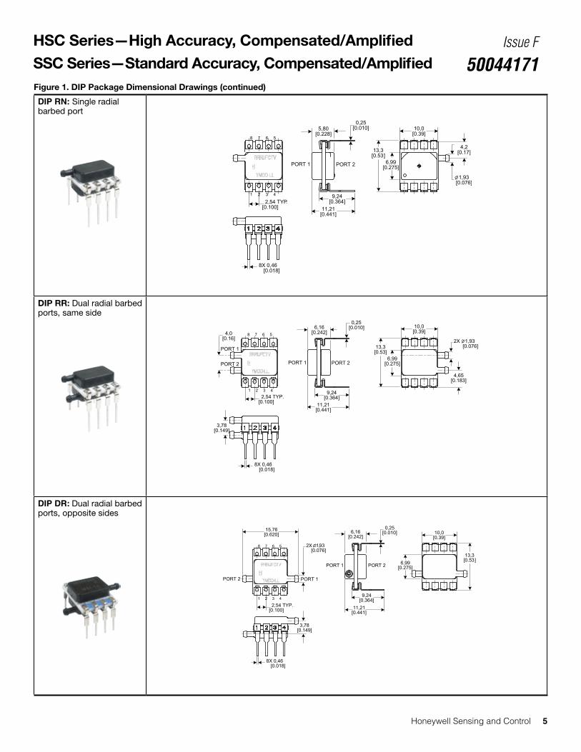
50044171Figure 1. DIP Package Dimensional Drawings (continued)
DIP RN: Single radial barbed port
DIP RR: Dual radial barbed ports, same side
DIP DR: Dual radial barbed ports, opposite sides
10,0[0.39]
PORT 1
1 2 3 4
8 7 6 5
6,16[0.242]
9,24[0.364]
2,54 TYP.[0.100]
15,76[0.620]
11,21[0.441]
2X 1,93 [0.076]
6,99[0.275]
8X 0,46 [0.018]
0,25[0.010]
PORT 1 PORT 2
3,78[0.149]
13,3[0.53]
PORT 2
PORT 1
13,3[0.53]
10,0[0.39]
6,99[0.275]
1 2 3 4
8 7 6 5
11,21[0.441]
9,24[0.364]
5,80[0.228]
2,54 TYP.[0.100]
8X 0,46 [0.018]
0,25[0.010]
1,93 [0.076]
4,2[0.17]
PORT 2
8X 0,46 [0.018]
13,3[0.53]
10,0[0.39]
6,99[0.275]
1 2 3 4
8 7 6 5
6,16[0.242]
2,54 TYP.[0.100] 11,21
[0.441]
9,24[0.364]
2X 1,93 [0.076]
4,65[0.183]
,25[0.010]
PORT 1 PORT 2
PORT 1
PORT 2
4,0[0.16]
3,78[0.149]
0

6 Honeywell Sensing and Control
HSC Series—High Accuracy, Compensated/Amplified
SSC Series—Standard Accuracy, Compensated/AmplifiedIssue F
50044171Figure 1. DIP Package Dimensional Drawings (continued)
DIP JN: Single radial barbless port
DIP JJ: Dual radial radial barbless ports, same side
1 2 3 4
8 X 0,46 [0.018]
11,92[0.469]
9,24[0.364]
2X 6,75 [0.266]
PORT 1
6,51[0.256] 4,76
[0.187] 1,9[0.07]
PORT 1
PORT 2
1,94[0.076]
8 7 6 5
2,54[0.100]
3,28[0.129]
2,21[0.087]
4,1[0.16]
4,1[0.16]
4,2[0.16]
9,91[0.390]
9,40[0.370]
2X 2,34 [0.092]
0,25[0.010]
7,00[0.276]
13,3[0.53]
1 2 3 4
8 X 0,461 [0.018]
11,92[0.469]
9,24[0.364]
2,34 [0.092]
6,75 [0.266]
PORT 1
7,58[0.298] 1,9
[0.07]
PORT 1
PORT 2
6,70[0.264]
8 7 6 5
3,28[0.129]
3,28[0.129]
7,00[0.276]
4,1[0.16]
9,91[0.390]
9,40[0.370]
0,25[0.010]
13,3[0.53]
Figure 2. SMT Package Dimensional Drawings (For reference only: mm [in])
SMT NN: No ports
13,3[0.53]
10,0[0.39]
6,99[0.275]
1 2 3 4
8 7 6 5
5,44[0.214]
2,54 TYP.[0.100] 6,41
[0.252]
4,80[0.189]
8X 0,46 [0.018]
PORT 1 PORT 2
PIN 1INDICATOR

Honeywell Sensing and Control 7
HSC Series—High Accuracy, Compensated/Amplified
SSC Series—Standard Accuracy, Compensated/AmplifiedIssue F
50044171Figure 2. SMT Package Dimensional Drawings (continued)
SMT AN: Single axial barbed port
SMT LN: Single axial barbless port
SMT RN: Single radial barbed port
13,3[0.53]
10,0[0.39]
6,99[0.275]
1 2 3 4
8 7 6 5
5,80[0.228]
2,54 TYP.[0.100] 6,77
[0.266]
4,80[0.189]
8X 0,46 [0.018]
PORT 1
1,93 DIA. [0.076]
4,2[0.17]
PORT 1 PORT 2
10,0[0.394]
6,99[0.275]
1 2 3 4
8 7 6 5
2,54 TYP.[0.100] 6,77
[0.266]
4,80[0.189]
5,80[0.228]
13,75[0.541]
8X 0,46 [0.018]
PORT 1PORT 2
2,47 DIA.[0.097]
13,3 [0.53]
PIN 1INDICATOR
1 2 3 4
8 7 6 5
10,0[0.39]
7,95[0.313]
13,75[0.541]
4,93 DIA.[0.194]
2,54 TYP.[0.100]
PORT
2PORT
1
6,77[0.266]
4,80[0.189] 8X 0,46
[0.018]
6,99[0.275]
13,3[0.53]
PIN 1INDICATOR

8 Honeywell Sensing and Control
HSC Series—High Accuracy, Compensated/Amplified
SSC Series—Standard Accuracy, Compensated/AmplifiedIssue F
50044171Figure 2. SMT Package Dimensional Drawings (continued)
SMT RR: Dual radial barbed ports, same side
SMT DR: Dual radial barbed ports, opposite sides
SMT JN: Single radial barbless port
1 2 3 4
8 7 6 5
PORT 1PORT 2
10,0[0.39]
6,99[0.275]
2X 2,93 [0.115]
15,8[0.62]
2,54 TYP.[0.100]
2X 1,93 DIA.[0.076]
6,77[0.266]
4,80[0.189]
6,16[0.242]
3,78[0.149]
8X 0,46 [0.018]
13,3[0.53]
10,0[0.39]
6,99[0.275]
1 2 3 4
8 7 6 5
6,16[0.242]
2,54 TYP.[0.100] 6,77
[0.266]
4,80[0.189]
8X 0,46 [0.018]
13,3[0.53]
4,6[0.18]
PORT 1
PORT 2
2X 1,93 DIA. [0.076]
PORT 1 PORT 2
4,0[0.16]
3,78[0.149]
1 2 3 4 8 X 0,461 [0.018]7,48
[0.294]
4,80[0.189]
2,34 [0.092] 13,3
[0.53]
6,75 [0.266]
PORT 1
6,51[0.256]
9,91[0.390]
1,87[0.074]
PORT 1
PORT 2
5,38[0.212]
8 7 6 59,40
[0.370]3,28
[0.129]2,21
[0.087]
7,00[0.276]
4,15[0.163]
2,54[0.100]
8 X 1,28 [0.050]
6,98[0.275]

Honeywell Sensing and Control 9
HSC Series—High Accuracy, Compensated/Amplified
SSC Series—Standard Accuracy, Compensated/AmplifiedIssue F
50044171
Figure 3. SIP Package Dimensional Drawings (For reference only: mm [in].)
SIP NN: No ports
SIP AA: Dual axial barbed ports, opposite sides
Figure 2. SMT Package Dimensional Drawings (continued)
SMT JJ: Dual radial barbless ports, same side
PORT 1 PORT 2
0,25[0.010]
10,0[0.39]
10,0[0.39]
2,54 TYP.[0.100]
15,2[0.60]
22,06[0.869]
2X 4.93 DIA.[0.194]
4X 0,51 [0.020]
2,54 TYP.[0.100]
10,0[0.39]
15,2[0.60]
10,0[0.39]
1 2 3 4
4X 0,51 [0.020]
4,87[0.192]
PORT 1 PORT 2
0,25[0.010]
1 2 3 4 8 X 0,461 [0.018]8,36
[0.329]
5,68[0.189]
2X 2,34 [0.092]
2X 6,75 [0.266]
PORT 1
7,58[0.298] 4,76
[0.187]
PORT 1
5,38[0.212]
8 7 6 53,28
[0.129]
7,00[0.276]
4,15[0.163]
2,54[0.100]
8 X 1,28 [0.050]
6,98[0.275]
PORT 2
4,162[0.1639]
9,91[0.390]
9,40[0.370]
13,3[0.53]

10 Honeywell Sensing and Control
HSC Series—High Accuracy, Compensated/Amplified
SSC Series—Standard Accuracy, Compensated/AmplifiedIssue F
50044171Figure 3. SIP Package Dimensional Drawings (continued)
SIP AN: Single axial barbed port
SIP LN: Single axial barbless port
SIP FF: Fastener mount, dual axial barbed ports, opposite sides
10,0[0.39]
15,2[0.60]
10,0[0.39]
1 2 3 4
2,54 TYP.[0.100]
PORT 1
PORT 2
0,25[0.010]
13,75[0.541]
4X 0,51 [0.020]
2,47 DIA.[0.097]
0,25[0.010] 2,54 TYP.
[0.100]
PORT 110,0[0.39]
4.93 DIA.[0.194]
10,0[0.39]
13,75[0.541]
15,2[0.60]
PORT 2
4X 0,51 [0.020]
0,25[0.010]
27,20[1.071]
10,44[0.411]
PORT 1PORT 2
2X 4,78 DIA.[0.188][
29,48[1.161]
23,12[0.910]
2X 3.94 DIA.0.155]
4X 0,51 [0.020]
2,54 TYP.[0.100]
17,78[0.700]
20,16[0.794]
Honeywell Sensing and Control 11
HSC Series—High Accuracy, Compensated/Amplified
SSC Series—Standard Accuracy, Compensated/AmplifiedIssue F
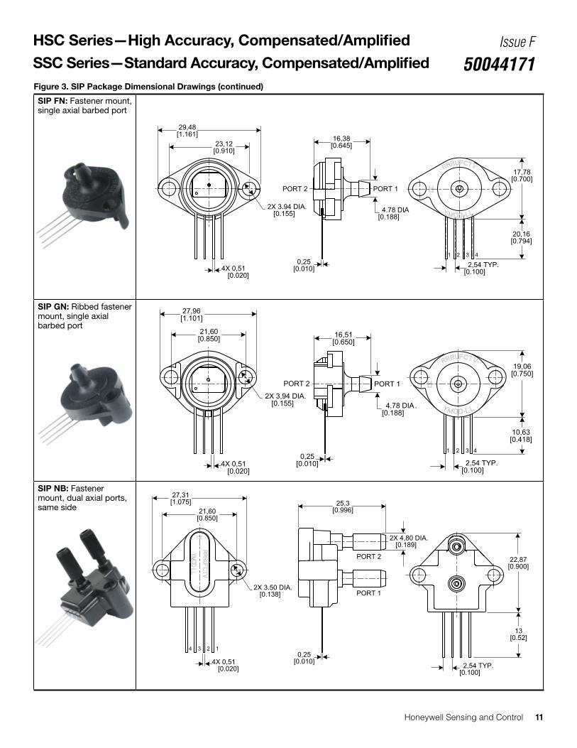
50044171Figure 3. SIP Package Dimensional Drawings (continued)
SIP FN: Fastener mount, single axial barbed port
SIP GN: Ribbed fastener mount, single axial barbed port
SIP NB: Fastener mount, dual axial ports, same side
17,78[0.700]
20,16[0.794]
2,54 TYP.[0.100]
0,25[0.010]
29,48[1.161]
23,12[0.910]
16,38[0.645]
2X 3.94 DIA.[0.155] 4.78 DIA.
[0.188]
4X 0,51 [0.020]
2,54 TYP.[0.100]
21,60[0.850]
PORT 1PORT 2
4.78 DIA.[0.188]
0,25[0.010]
2X 3,94 DIA.[0.155]
27,96[1.101]
16,51[0.650]
19,06[0.750]
10,63[0.418]
4X 0,51 [0.020]
0,25[0.010] 2,54 TYP.
[0.100]
22,87[0.900]
13[0.52]
2X 3.50 DIA.[0.138]
21,60[0.850]
27,31[1.075] 25,3
[0.996]
PORT 1
PORT 2
4X 0,51 [0.020]
2X 4,80 DIA.[0.189]

12 Honeywell Sensing and Control
HSC Series—High Accuracy, Compensated/Amplified
SSC Series—Standard Accuracy, Compensated/AmplifiedIssue F
50044171Figure 3. SIP Package Dimensional Drawings (continued)
SIP RN: Single radial barbed port
SIP RR: Dual radial barbed ports, same side
SIP DR: Dual radial barbed ports, opposite sides
0,25[0.010] 2,54 TYP.
[0.100]
PORT 1
PORT 2
10,0[0.39]
15,2[0.60]
10,0[0.39]
1 2 3 4
5,80[0.228]
1,92 DIA.[0.076]
4X 0,51 [0.020]
PORT 1
0,25[0.010] 2,54 TYP.
[0.100]
PORT 1
PORT 2
1 2 3 4
10,0[0.39]
15,2[0.60]
10,0[0.39] 2X 1,92 DIA.
[0.076]
6,16[0.243]
4X 0,51 [0.020]
PORT 1
PORT 2
0,25[0.010] 2,54 TYP.
[0.100]
PORT 1PORT 2
1 2 3 4
10,0[0.39]
10,0[0.39]
15,2[0.60]
6,16[0.243]
2X 4.93 DIA.[0.194]
15,8[0.62]
4X 0,51 [0.020]
Honeywell Sensing and Control 13
HSC Series—High Accuracy, Compensated/Amplified
SSC Series—Standard Accuracy, Compensated/AmplifiedIssue F
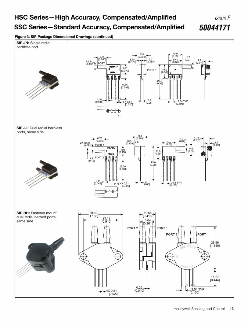
50044171Figure 3. SIP Package Dimensional Drawings (continued)
SIP JN: Single radial barbless port
SIP JJ: Dual radial barbless ports, same side
SIP HH: Fastener mount dual radial barbed ports, same side
1 2 3 4
4X 0,51 [0.020]
7,58[0.298]
3,28[0.129]
6,75[0.266]
4,76[0.187]
5,8[0.23]
1,7[0.07]10,0
[0.39]PORT 1
PORT 2
1,14 [0.045] 2,54 TYP.
[0.100]
1,9[0.07]
7,00[0.276]
15,20[0.598]
10,0[0.39]
25,0[0.98]
2,1 [0.08]
2X 2,34 [0.092]
4,2[0.16]
1 2 3 4
4 X 0,51 [0.020]
7,58[0.298]
3,28[0.129]
6,75[0.266]
1,7[0.07]
10,0[0.39]
PORT 1
PORT 2
1,14 [0.045] 2,54 TYP.
[0.100]
1,9[0.07]
7,00[0.276]
15,20[0.598]
10,0[0.39]
25,0[0.98]
2,1 [0.08]
2,2[0.087]
9,40[0.370] 2,34
[0.092]
0,25[0.010]
28,96[1.140]
2,54 TYP.[0.100]
PORT 1PORT 2
29,62[1.166]
23,12[0.910]
11,27[0.444]
6,64[0.261]
10,58[0.416]
4X 0,51 [0.020]
PORT 1PORT 2

14 Honeywell Sensing and Control
HSC Series—High Accuracy, Compensated/Amplified
SSC Series—Standard Accuracy, Compensated/AmplifiedIssue F
50044171Figure 3. SIP Package Dimensional Drawings (continued)
SIP HN: Fastener mount single radial barbed port
SIP MN: Manifold mount, outer diameter seal
SIP SN: Manifold mount, inner diameter seal
28,96[1.140]
11,27[0.444]
23,12[0.910]
0,25[0.010] 2,54 TYP.
[0.100]
2X 3,94 DIA.[0.155]
7,97[0.314] 4,78 DIA.
[0.188]
4X 0,51 [0.020]
PORT 2
2,54 TYP.[0.100]
0,25[0.010]
PORT 1PORT 2
15,24 DIA.[0.600]
12,5[0.49]
5,36[0.211]
4X 0,51 [0.020]
2,54 TYP.[0.100]
1 2 3 4
13,11[0.516]
12,57[0.495]
15,6[0.61]
5,1[0.20]
4X 0,51 [0.020]
PORT 1
PORT 2

Honeywell Sensing and Control 15
HSC Series—High Accuracy, Compensated/Amplified
SSC Series—Standard Accuracy, Compensated/AmplifiedIssue F
50044171
Figure 4. Recommended PCB Pad Layouts
DIP SMT SIP
0,914 [0.036]
2,54[0.100]
13,08[0.515]
0,813 [0.032]
2,54[0.100]
2,54[0.100]
9,40[0.370]
2,032[0.080]
1,143[0.045]
Table 6. Pinouts for DIP and SMT Packages
Output Type Pin 1 Pin 2 Pin 3 Pin 4 Pin 5 Pin 6 Pin 7 Pin 8
I2C GND Vsupply SDA SCL NC NC NC NC
SPI GND Vsupply MISO SCLK SS NC NC NC
Analog NC Vsupply Vout GND NC NC NC NC
Table 7. Pinouts for SIP Packages
Output Type Pin 1 Pin 2 Pin 3 Pin 4
I2C GND Vsupply SDA SCL
Analog NC Vsupply Vout GND

16 Honeywell Sensing and Control
HSC Series—High Accuracy, Compensated/Amplified
SSC Series—Standard Accuracy, Compensated/AmplifiedIssue F
50044171
Figure 5. HSC Series Nomenclature and Order Guide
H S C D N N N 1 5 0 P G A A 3Product Series
Package
008B
Pressure PortDIP
HSC High Accuracy, Compensated/Amplified
Options5, 6
SMT
NN
AADual axialbarbed ports,opposite sides
SIP
AN
LN
FFFastenermount, dual axial barbed ports, opposite sides
FNFastenermount, single axial barbed port
GNRibbedfastener mount,single axialbarbed port
NBFastenermount, dual axial ports, same side
Single radialbarbed portRN
HHFastenermount, dualradial barbedports, same side
HNFastenermount, singleradial barbedport
MNManifoldmount, outerdiameter seal
Single axial barbed port
Single axial barbless port
No portsNN
AN
LN
Single radialbarbed port
Dual radialbarbed ports,same side
Dual radialbarbed ports,opposite sides
RN
RR
DR
Single axial barbed port
Single axial barbless port
No portsNN
AN
LN
Single radialbarbed port
Dual radialbarbed ports,same side
Dual radialbarbed ports,opposite sides
RN
RR
DR
Single axial barbed port
Single axial barbless port
No ports
SNManifoldmount, innerdiameter seal
Dual radialbarbed ports,opposite sides
DR
Dual radialbarbed ports,same side
RR
Single radialbarbless port
Dual radialbarbless ports,same side
JN
JJ
Single radialbarbless port
Dual radialbarbless ports,same side
JN
JJDual radialbarbless ports,same side
JJ
Single radialbarbless portJN
D DIP (Dual Inline Pin)
M SMT (Surface Mount Technology)
S SIP (Single Inline Pin)
Output Type2
Supply Voltage
For example, HSCDNNN150PGAA3 de�nes an HSC Series TruStability® Pressure Sensor, DIP package, NN pressure port, nospecial options,150 psi gage pressure range, analog output type, 10% to 90% of Vsupply transfer function, 3.3 Vdc supply voltage.
Pressure Range3, 4
N Dry gases only, no diagnostics
D Dry gases only, diagnostics on
T Liquid media on Port 1, no diagnostics
V Liquid media on Port 1, diagnostics on
A Analog
S SPI
2 I2C, Address 0x28
3 I2C, Address 0x38
4 I2C, Address 0x48
5 I2C, Address 0x58
6 I2C, Address 0x68
7 I2C, Address 0x78
3 3.3 Vdc
5 5.0 Vdc
1The transfer function limits define the output of the sensor at a given pressure input. By specifying Pmin. and Pmax., the output at Pmin. and Pmax., the complete transfer function of the sensor is defined. See the graphical representations of the transfer function in the product datasheet, Figure 2. For other available transfer functions contact Honeywell Customer Service. 2SPI output function is not available in SIP package.3Custom pressure ranges are available. Contact Honeywell Customer Service for more information.4See the explanation of sensor pressure types in the product datasheet, Table 4. 5See the CAUTION in this document.6Options T and V are only available on pressure ranges ±60 mbar to ±10 bar | ±6 kPa to ±1 MPa | ±1 psi to ±150 psi.
±0.5 inH2O to ±150 psi±1.6 mbar to ±10 barAbsolute
015PA030PA060PA100PA150PA
Differential
Absolute001BA
1.6BA 2.5BA 004BA 006BA 010BA
Differential
Gage
0.5ND001ND 002ND004ND 005ND 010ND020ND 030ND 001PD 005PD 015PD 030PD 060PD
Gage001NG002NG004NG005NG010NG 020NG030NG001PG 005PG015PG030PG 060PG 100PG 150PG
1.6MD2.5MD 004MD 006MD 010MD
016MD 025MD 040MD
060MD 100MD 160MD 250MD 400MD 600MD 001BD 1.6BD 2.5BD 004BD
2.5MG004MG006MG010MG016MG025MG040MG060MG100MG160MG250MG400MG600MG001BG1.6BG2.5BG 004BG006BG 010BG
0 bar to 1 bar
0 bar to 1.6 bar
0 bar to 2.5 bar
0 bar to 4 bar
0 bar to 6 bar
0 bar to 10 bar
±1.6 mbar
±2.5 mbar
±4 mbar
±6 mbar
±10 mbar
±16 mbar
±25 mbar
±40 mbar
±60 mbar
±100 mbar
±160 mbar
±250 mbar
±400 mbar
±600 mbar
±1 bar
±1.6 bar
±2.5 bar
±4 bar
0 mbar to 2.5 mbar
0 mbar to 4 mbar
0 mbar to 6 mbar
0 mbar to 10 mbar
0 mbar to 16 mbar
0 mbar to 25 mbar
0 mbar to 40 mbar
0 mbar to 60 mbar
0 mbar to 100 mbar
0 mbar to 160 mbar
0 mbar to 250 mbar
0 bar to 400 mbar
0 bar to 600 mbar
0 bar to 1 bar
0 bar to 1.6 bar
0 bar to 2.5 bar
0 bar to 4 bar
0 bar to 6 bar
0 bar to 10 bar
±160 Pa to ±1 MPaAbsolute
100KA
160KA 250KA 400KA 600KA 001GA
Differential
Gage
160LD250LD 400LD600LD001KD
1.6KD2.5KD004KD006KD010KD016KD025KD040KD060KD100KD160KD250KD400KD
250LG400LG600LG001KG1.6KG2.5KG004KG006KG010KG016KG025KG040KG060KG100KG160KG250KG400KG600KG001GG
0 kPa to 100 kPa
0 kPa to 160 kPa
0 kPa to 250 kPa
0 kPa to 400 kPa
0 kPa to 600 kPa
0 kPa to 1 MPa
±160 Pa
±250 Pa
±400 Pa
±600 Pa
±1 kPa
±1.6 kPa
±2.5 kPa
±4 kPa
±6 kPa
±10 kPa
±16 kPa
±25 kPa
±40 kPa
±60 kPa
±100 kPa
±160 kPa
±250 kPa
±400 kPa
0 Pa to 250 Pa
0 Pa to 400 Pa
0 Pa to 600 Pa
0 kPa to 1 kPa
0 kPa to 1.6 kPa
0 kPa to 2.5 kPa
0 kPa to 4 kPa
0 kPa to 6 kPa
0 kPa to 10 kPa
0 kPa to 16 kPa
0 kPa to 25 kPa
0 kPa to 40 kPa
0 kPa to 60 kPa
0 kPa to 100 kPa
0 kPa to 160 kPa
0 kPa to 250 kPa
0 kPa to 400 kPa
0 kPa to 600 kPa
0 kPa to 1 MPa
0 inH2O to 1 inH2O
0 inH2O to 2 inH2O
0 inH2O to 4 inH2O
0 inH2O to 5 inH2O
0 inH2O to 10 inH2O
0 inH2O to 20 inH2O
0 inH2O to 30 inH2O
0 psi to 1 psi
0 psi to 5 psi
0 psi to 15 psi
0 psi to 30 psi
0 psi to 60 psi
0 psi to 100 psi
0 psi to 150 psi
±0.5 inH2O
±1 inH2O
±2 inH2O
±4 inH2O
±5 inH2O
±10 inH2O
±20 inH2O
±30 inH2O
±1 psi
±5 psi±15 psi
±30 psi
±60 psi
0 psi to 15 psi
0 psi to 30 psi
0 psi to 60 psi
0 psi to 100 psi
0 psi to 150 psi
Transfer Function1
ABCF
10% to 90% of Vsupply (analog), 214 counts (digital)
5% to 95% of Vsupply (analog), 214 counts (digital)
5% to 85% of Vsupply (analog), 214 counts (digital)
4% to 94% of Vsupply (analog), 214 counts (digital)

Honeywell Sensing and Control 17
HSC Series—High Accuracy, Compensated/Amplified
SSC Series—Standard Accuracy, Compensated/AmplifiedIssue F
50044171Figure 6. SSC Series Nomenclature and Order Guide
S S C D N N N 1 5 0 P G A A 3
Product Series
Package
008B
Pressure PortDIP
SSC Standard Accuracy, Compensated/Amplified
Options5, 6
SMT
NN
AADual axialbarbed ports,opposite sides
SIP
AN
LN
FFFastenermount, dual axial barbed ports, opposite sides
FNFastenermount, single axial barbed port
GNRibbedfastener mount,single axialbarbed port
NBFastenermount, dual axial ports, same side
Single radialbarbed portRN
HHFastenermount, dualradial barbedports, same side
HNFastenermount, singleradial barbedport
MNManifoldmount, outerdiameter seal
Single axial barbed port
Single axial barbless port
No portsNN
AN
LN
Single radialbarbed port
Dual radialbarbed ports,same side
Dual radialbarbed ports,opposite sides
RN
RR
DR
Single axial barbed port
Single axial barbless port
No portsNN
AN
LN
Single radialbarbed port
Dual radialbarbed ports,same side
Dual radialbarbed ports,opposite sides
RN
RR
DR
Single axial barbed port
Single axial barbless port
No ports
SNManifoldmount, innerdiameter seal
Dual radialbarbed ports,opposite sides
DR
Dual radialbarbed ports,same side
RR
Single radialbarbless port
Dual radialbarbless ports,same side
JN
JJ
Single radialbarbless port
Dual radialbarbless ports,same side
JN
JJDual radialbarbless ports,same side
JJ
Single radialbarbless portJN
D DIP (Dual Inline Pin)
M SMT (Surface Mount Technology)
S SIP (Single Inline Pin)
Output Type2
Transfer Function1
Supply Voltage
For example, SSCDNNN150PGAA3 de�nes an SSC Series TruStability® Pressure Sensor, DIP package, NN pressure port, no special options,150 psi gage pressure range, analog output type, 10% to 90% of Vsupply transfer function, 3.3 Vdc supply voltage.
N Dry gases only, no diagnostics
D Dry gases only, diagnostics on
T Liquid media on Port 1, no diagnostics
V Liquid media on Port 1, diagnostics on
A Analog
S SPI
2 I2C, Address 0x28
3 I2C, Address 0x38
4 I2C, Address 0x48
5 I2C, Address 0x58
6 I2C, Address 0x68
7 I2C, Address 0x78
3 3.3 Vdc
5 5.0 Vdc
1The transfer function limits define the output of the sensor at a given pressure input. By specifying Pmin. and Pmax., the output at Pmin. and Pmax., the complete transfer function Of the sensor is defined. See the graphical representations of the transfer function in the product datasheet, FIgure 2. For other available transfer functions contact Honeywell Customer Service. 2SPI output function is not avilable in SIP package.3Custom pressure ranges are available. Contact Honeywell Customer Service for more information.4See the explanation of sensor pressure types in the product datasheet, Table 4. 5See the CAUTION in this document.6Options T and V are only available on pressure ranges ±60 mbar to ±10 bar | ±6 kPa to ±1 MPa | ±1 psi to ±150 psi.
ABCF
10% to 90% of Vsupply (analog), 214 counts (digital)
5% to 95% of Vsupply (analog), 214 counts (digital)
5% to 85% of Vsupply (analog), 214 counts (digital)
4% to 94% of Vsupply (analog), 214 counts (digital)
Pressure Range3, 4
±0.5 inH2O to ±150 psi±1.6 mbar to ±10 barAbsolute
015PA030PA060PA100PA150PA
Differential
Absolute001BA
1.6BA 2.5BA 004BA 006BA 010BA
Differential
Gage
0.5ND001ND 002ND004ND 005ND 010ND020ND 030ND 001PD 005PD 015PD 030PD 060PD
Gage001NG002NG004NG005NG010NG 020NG030NG001PG 005PG015PG030PG 060PG 100PG 150PG
1.6MD2.5MD 004MD 006MD 010MD
016MD 025MD 040MD
060MD 100MD 160MD 250MD 400MD 600MD 001BD 1.6BD 2.5BD 004BD
2.5MG004MG006MG010MG016MG025MG040MG060MG100MG160MG250MG400MG600MG001BG1.6BG2.5BG 004BG006BG 010BG
0 bar to 1 bar
0 bar to 1.6 bar
0 bar to 2.5 bar
0 bar to 4 bar
0 bar to 6 bar
0 bar to 10 bar
±1.6 mbar
±2.5 mbar
±4 mbar
±6 mbar
±10 mbar
±16 mbar
±25 mbar
±40 mbar
±60 mbar
±100 mbar
±160 mbar
±250 mbar
±400 mbar
±600 mbar
±1 bar
±1.6 bar
±2.5 bar
±4 bar
0 mbar to 2.5 mbar
0 mbar to 4 mbar
0 mbar to 6 mbar
0 mbar to 10 mbar
0 mbar to 16 mbar
0 mbar to 25 mbar
0 mbar to 40 mbar
0 mbar to 60 mbar
0 mbar to 100 mbar
0 mbar to 160 mbar
0 mbar to 250 mbar
0 bar to 400 mbar
0 bar to 600 mbar
0 bar to 1 bar
0 bar to 1.6 bar
0 bar to 2.5 bar
0 bar to 4 bar
0 bar to 6 bar
0 bar to 10 bar
±160 Pa to ±1 MPaAbsolute
100KA
160KA 250KA 400KA 600KA 001GA
Differential
Gage
160LD250LD 400LD600LD001KD
1.6KD2.5KD004KD006KD010KD016KD025KD040KD060KD100KD160KD250KD400KD
250LG400LG600LG001KG1.6KG2.5KG004KG006KG010KG016KG025KG040KG060KG100KG160KG250KG400KG600KG001GG
0 kPa to 100 kPa
0 kPa to 160 kPa
0 kPa to 250 kPa
0 kPa to 400 kPa
0 kPa to 600 kPa
0 kPa to 1 MPa
±160 Pa
±250 Pa
±400 Pa
±600 Pa
±1 kPa
±1.6 kPa
±2.5 kPa
±4 kPa
±6 kPa
±10 kPa
±16 kPa
±25 kPa
±40 kPa
±60 kPa
±100 kPa
±160 kPa
±250 kPa
±400 kPa
0 Pa to 250 Pa
0 Pa to 400 Pa
0 Pa to 600 Pa
0 kPa to 1 kPa
0 kPa to 1.6 kPa
0 kPa to 2.5 kPa
0 kPa to 4 kPa
0 kPa to 6 kPa
0 kPa to 10 kPa
0 kPa to 16 kPa
0 kPa to 25 kPa
0 kPa to 40 kPa
0 kPa to 60 kPa
0 kPa to 100 kPa
0 kPa to 160 kPa
0 kPa to 250 kPa
0 kPa to 400 kPa
0 kPa to 600 kPa
0 kPa to 1 MPa
0 inH2O to 1 inH2O
0 inH2O to 2 inH2O
0 inH2O to 4 inH2O
0 inH2O to 5 inH2O
0 inH2O to 10 inH2O
0 inH2O to 20 inH2O
0 inH2O to 30 inH2O
0 psi to 1 psi
0 psi to 5 psi
0 psi to 15 psi
0 psi to 30 psi
0 psi to 60 psi
0 psi to 100 psi
0 psi to 150 psi
±0.5 inH2O
±1 inH2O
±2 inH2O
±4 inH2O
±5 inH2O
±10 inH2O
±20 inH2O
±30 inH2O
±1 psi
±5 psi±15 psi
±30 psi
±60 psi
0 psi to 15 psi
0 psi to 30 psi
0 psi to 60 psi
0 psi to 100 psi
0 psi to 150 psi

50044171-F-EN IL50 August 2014© 2014 Honeywell International Inc. All rights reserved.
HSC Series—High Accuracy, Compensated/Amplified
SSC Series—Standard Accuracy, Compensated/AmplifiedIssue F
50044171
Sensing and Control
Honeywell
1985 Douglas Drive North
Golden Valley, MN 55422
honeywell.com
WARRANTYHoneywell warrants goods of its manufacture as being free of defective materials and faulty workmanship. Honeywell’s standard product warranty applies unless agreed to otherwise by Honeywell in writing; please refer to your order acknowledgement or consult your local sales office for specific warranty details. If warranted goods are returned to Honeywell during the period of coverage, Honeywell will repair or replace, at its option, without charge those items it finds defective. The foregoing is buyer’s sole remedy and is in lieu of all warranties, expressed or implied, including those of merchantability and fitness for a particular purpose. In no event shall Honeywell be liable for consequential, special, or indirect damages.
While we provide application assistance personally, through our literature and the Honeywell web site, it is up to the customer to determine the suitability of the product in the application.
Specifications may change without notice. The information we supply is believed to be accurate and reliable as of this printing. However, we assume no responsibility for its use.
WARNINGPERSONAL INJURY
DO NOT USE these products as safety or emergency stop devices or in any other application where failure of the product could result in personal injury.
Failure to comply with these instructions could result in death or serious injury.
SALES AND SERVICEHoneywell serves its customers through a worldwide network of sales offices, representatives and distributors. For application assistance, current specifications, pricing or name of the nearest Authorized Distributor, contact your local sales office or:
E-mail: [email protected]: sensing.honeywell.comPhone and Fax:Asia Pacific +65 6355-2828 +65 6445-3033 FaxEurope +44 (0) 1698 481481 +44 (0) 1698 481676 FaxLatin America +1-305-805-8188 +1-305-883-8257 FaxUSA/Canada +1-800-537-6945 +1-815-235-6847 +1-815-235-6545 Fax