installation hs-6008 / eh020 - continental girbau · some fault localisation procedures require...
TRANSCRIPT

Cod. 428938
Rev. 08/0219
Model From serial #
HS-6008 2,080,001
EH020 1,430,001
Installation instructions for washers
HS-6008 / EH020
GIRBAU, SA Crta de Manlleu, km. 1 1
08500 VIC (Barcelona) SPAIN
National sales: Tel.(+ 34) 902 300 359 [email protected] International sales: Tel.(+ 34) 938 862 219 [email protected] Service: Tel.(+ 34) 902 300 357 [email protected]
For USA and CANADA: CONTINENTAL GIRBAU Inc. 2500 State Road 44
WI 54904 Oshkosh USA Tel. 1(920) 231-8222 [email protected] www.continentalgirbau.com
EN Installation
HS-6008
EH020

Contents 2
Cod. 428938
Rev. 08/0219
CONTENTS
SAFETY INSTRUCTIONS ................................................................................................................................ 3
1. TECHNICAL SPECIFICATIONS .................................................................................................................... 6
Tools needed for installation ................................................................................................................... 6
Accessories in machine ........................................................................................................................... 6
EU Declaration of conformity .................................................................................................................. 7
Installation specifications ......................................................................................................................... 8
Electrical requirements .......................................................................................................................... 10
Connection table explanation ................................................................................................................ 11
2. TRANSPORT AND LOCATION ................................................................................................................... 12
Transport of crated machines ............................................................................................................... 12
Washer location. Conditions. ................................................................................................................ 12
Removal of shipping braces .................................................................................................................. 13
Washing machine levelling .................................................................................................................... 13
Installation on a very irregular floor ....................................................................................................... 14
3. INSTALLATION ........................................................................................................................................... 15
Gravity drain .......................................................................................................................................... 15
Pump drain ............................................................................................................................................ 16
Water supply ......................................................................................................................................... 17
Electrical connection. Permanently connected appliances. .................................................................. 19
3.4.1. Previous requirements ................................................................................................................... 19 3.4.2. Installation characteristics. ............................................................................................................. 19 3.4.3. Machine electrical connection ........................................................................................................ 20 Electrical connection. 1ph, 120V units with power cord (USA / CANADA only) ................................... 20
External dosing (option) ........................................................................................................................ 21
3.6.1. External dosing electrical connection ............................................................................................ 21 3.6.2. External dosing hoses connection ................................................................................................. 21 Tensioning belts .................................................................................................................................... 22
Initial Start-up ........................................................................................................................................ 23
Emergency stop in coin-op installations ................................................................................................ 23
Wash cycle start-up from an external device to the washing machine ............................................... 24
3.10.1. Connecting to a central vending unit and configuring the machine ............................................. 24

Safety instructions 3
Cod. 428938
Rev. 08/0219
CAUTION!
TRANSPORT, INSTALLATION, INSPECTION, MAINTENANCE, REPAIR OR MODIFICATION ROUTINES ON GIRBAU EQUIPMENT
1. The actions described in these instructions are strictly reserved for contractually AUTHORISED TECHNICAL SERVICES (ATS) and personnel who have successfully completed training by Girbau SA.
2. The company responsible for the Authorised Technical Service accepts full liability for the work done and any possible consequences that may derive from it.
3. Any actions carried out by personnel who are not authorised by the manufacturer will be considered to be improper and will result in the automatic voiding of the machine’s warranty.
4. The manufacturer will not accept responsibility for any physical and/or material damage caused by actions performed on the machine undertaken by unauthorised personnel.
5. Do not store or install the machine in areas exposed to the ELEMENTS or where it may be splashed by water.
6. The room where the machine is located MUST comply with the environmental conditions (air venting, temperature, humidity, etc.) specified in the technical specifications table. NEVER INSTALL THE MACHINE IN ENVIRONMENTS where it will be splashed with water or where there is a very high level of humidity in the atmosphere.
7. All installations required for the proper operation of the machine MUST be carried out by a duly accredited Registered Installation Contractors, in compliance with the legal regulations applicable in the country of use.
8. Once the corresponding operation has been performed, the ATS staff must perform the final machine inspection.
9. Avoid carrying out any action on the machine without having first read and understood the machine’s Installation and Operating Manuals, paying special attention to the Safety Instructions.
10. In any action that modifies the values of the machine’s specifications plate, it should be borne in mind that:
- It is the responsibility of the ATS to check that the external installation for the machine has been modified and adapted to the new requirements, particularly to those regarding ducting and electrical protection.
- It is the responsibility of the ATS to update the specifications plate, in accordance with the new operation conditions, once the final machine inspection has been performed.
11. Carrying out transport, installation, inspection routines, adjustments, maintenance, repairs, cleaning or any work on the machines without applying safety measures or having the necessary technical know-how can lead to ELECTRICAL SHOCK OR SERIOUS ACCIDENTS.
12. When tools designed for specific transport, installation, maintenance and repair routines are available, their use is compulsory in order to avoid unnecessary risks.
13. Before carrying out any procedures on machines fitted with pneumatic or hydraulic circuits:
- Make the machines COMPLETELY SAFE by following the instructions set out in the corresponding Manuals or by wedging them with wooden blocks where necessary.
- Bear in mind that working on a component without having previously understood the role that it performs in the circuit as a whole involves a high risk of suffering a SERIOUS ACCIDENT.
14. BEFORE CARRYING OUT ANY inspection routine, adjustment, maintenance, repairs, cleaning or any work on the machine, DISCONNECT IT FROM ALL THE ENERGY SOURCES.
- COMPLETELY disconnect the machine from the power supply and prevent the possibility of accidental reconnection by mechanically locking the automatic external switch and/or the switch breaker. Stopping the machine with the NORMAL STOP key or push-button is not enough.
- Disconnect the electrical connection of any circuit external to the machine; for example external dosing equipment, external vending units, folders or ironer feeders. These circuits are independent of the supply to the machine.
- Before beginning any procedure on machines equipped with an inverter or equipment with

Safety instructions 4
Cod. 428938
Rev. 08/0219
capacitative loads, wait for at least five minutes (10 minutes on equipment with a power rating greater than 25 kW) after the electrical disconnection, to eliminate risk of residual voltage.
- Close and mechanically lock the manual WATER, GAS, STEAM, THERMAL OIL, COMPRESSED AIR, etc. supply valves.
- Check that the water bath has COMPLETELY drained, that no part of the machine is at an excessively high temperature and that no parts are in movement through inertia.
15. DANGER! Some fault localisation procedures require checking at different points of the electric circuit with the machine connected to the power supply and other supply sources. When carrying out these procedures, respect the following instructions:
- The appropriate checks must be carried out by ONLY ONE PERSON.
- During these procedures, ONLY remove the protective covers from the electric circuit and/or the inverter. Never remove the covers protecting the moving parts of the machine.
16. THE MANUFACTURER ACCEPTS NO RESPONSIBILITY IF THESE SAFETY INSTRUCTIONS AND ALL THE INFORMATION IN THE CORRESPONDING MANUALS ARE NOT FOLLOWED. KEEP THESE INSTRUCTIONS IN A SAFE PLACE.

Safety instructions 5
Cod. 428938
Rev. 08/0219
HAZARD AND PROHIBITION SYMBOLS USED IN MACHINE LABELLING
Electrical risk Protection guard for electric components.
High temperature risk Operate with caution. Use appropriate protections.
Mechanical risk Protection guard for moving parts.
Risk of inhaling harmful or irritant vapours Keep the doors/covers closed. Use appropriate protections.
Flame risk (only on some machines) Protective guard for flame.
Risk of falling Use proper access and safety methods.
Access prohibited
SYMBOLS USED IN THIS MANUAL
Symbol used to highlight a possible HAZARD, WARNING or NOTE.
This symbol is used to emphasise a particular explanation.
TRANSLATION OF ORIGINAL MANUAL

Technical specifications 6
Cod. 428938
Rev. 08/0219
1. TECHNICAL SPECIFICATIONS
Tools needed for installation Shipping restraints ........................... open end wrench 1/2 in (13mm)
Legs fixing ...................................... open end wrench 11/16 in (17 mm)
Legs fixing and clamps ...................... nut driver 7 mm
Water inlet coupling .......................... open end wrench 1-3/8 in (34 mm)
Covers fixing ................................... TORX T20 screwdriver.
Covers fixing ................................... TORX T25 screwdriver.
Water inlet hoses ............................. slip-joint pliers or pipe wrench diam. 1-1/2 in. (35 mm).
Electrical connection ......................... Phillips 2 screwdriver (#2)
External dosing connection ................ slotted-head screwdriver 3 mm
Vending circuit connection ................. slotted-head screwdriver 3 mm & Philips 1 (#1)
Accessories in machine Keep all machine instructions in a safe place.
ACCESSORIES QUANTITY NOTES
Leg rubber pad ..................................... 4 Levelling parts ...................................... 3 Open washer 0.06 in (1.5 mm) ................. 2 Open washer 0.12 in (3 mm).................... 3 Drain elbow ......................................... 1 (1) Clamp 50-70 ........................................ 1 (1) Drain hose ........................................... 1 (2) Drain hose support ................................ 1 (2) Elastic clamp ........................................ 1 (2) Clamp ................................................. 1 (2) Hose clamp ......................................... 1 (2) Clamp securing screw ............................ 1 (2) Cold water inlet hose ............................. 1 (3) Hot water inlet hose ............................... 1 (3) Water inlet coupling ............................... 2 (4) Water inlet gasket ................................. 2 (4) Top cover lock key ................................ 1 Microprocessor front lock key................... 1 (5) Coin meter box lock key ........................ 1(6) (7) Coin meter tokens ............................... 10 (6) (7) Fuses 8A ............................................. 1 Fuses 2.5A .......................................... 2 Installation handbook ............................. 1 Operation handbook .............................. 1 Parts handbook .................................... 1 (7) Documentation ................................... - - (7)
(1) machines with gravity drain
(2) machines with pump drain
(3) not available USA / Canada
(4) available USA / Canada only
(5) machines with front dispenser only
(6) Coin Control models only
(7) depending on target country

Technical specifications 7
Cod. 428938
Rev. 08/0219
EU Declaration of conformity
Manufacturer: GIRBAU S.A.
Address: Ctra. de Manlleu, km 1, 08500 Vic, Barcelona, SPAIN
Identification of the machine
Generic denomination:
Washer extractor Lavadora – centrifugadora Wasch – und Schleudermaschine Laveuse – essoreuse Lavatrice – centrifugatrice Rentadora – centrifugadora Máquina de lavar – centrifugar
洗衣机 – 脱水机
Function:
Washing in a water bath and extracting textiles Lavar en baño de agua y centrifugar géneros textiles Das Waschen im Waschbad und das Ausschleudern von Textilien Laver en bain d'eau et essorer textiles Lavare in bagno d'acqua e centrifugare tessuti Rentar en bany d’aigua i centrifugar teixits Lavagem com banho de água e centrifugação de gêneros têxteis
纺织物的湿洗和脱水
Type:
Front loading Carga frontal Frontladung Chargement frontal Carico frontale Càrrega frontal Carga frontal
前装式
Model: HS-6008 The manufacturer declares under its sole responsibility that the specified equipment has been manufactured in compliance with:
El fabricante declara bajo su exclusiva responsabilidad que el producto especificado se ha fabricado conforme a:
Der Hersteller bestätigt, dass das vorstehend bezeichnete Produkt gemäß den folgenden Richtlinien:
Le fabricant déclare, sous sa seule responsabilité, que le produit spécifié a été fabriquée conformément á:
Il fabbricante dichiara, sotto la sua esclusiva responsabilità, che il prodotto specificato é fabbricato secondo:
El fabricant declara, sota la seva exclusiva responsabilitat, que el producte especificat s’ha fabricat conforme a:
O fabricante declara sob a sua inteira responsabilidade que o produto referido é fabricado em conformidade com:
制造商全权声明,指定产品的制造符合以下要求:
2006/42/EC Machine Safety Directive
Main harmonized standards: EN ISO 10472-1:2008, EN ISO 10472-2:2008, EN 12100:2010, EN 13849-1:2015
2014/35/EU Low Voltage Directive
Main harmonized standards: EN 60335-1:2012, EN 60335-2-7:2010
2014/30/EU Electromagnetic Compatibility Directive
Main harmonized standards: EN 55014-1:2006, EN 55014-2:2015, EN 61000-3-2:2014, EN 61000-3-3:2013
2011/65/EU Hazardous Substances in Electrical and Electronic Equipment Directive
Main harmonized standards: EN 50581:2012
2012/19/EU Waste Electrical and Electronic Equipment Directive (not a CE Marking Directive)

Technical specifications 8
Cod. 428938
Rev. 08/0219
Installation specifications
General specifications MODEL UNITS HS-6008 / EH020
DRY LINEN CAPACITY kg 1/10 (lbs.) 8 (17.7)
SPIN r.p.m. 580 / 970
factor G 101 / 283
WASHING SPEED (max) r.p.m. 50
STATIC FORCE TRANSMITTED kg (lbs.) 154 (340)
DYNAMIC FORCE TRANSMITTED kg (lbs.) 52 (115)
FREQUENCY OF THE DYNAMIC FORCE Hz 16.2
MAXIMUM THERMAL SHOCK ºC (ºF) 90 (162)
KINETIC ENERGY kJ 12.76
MAXIMUM SOUND LEVEL dbA < 70
PROTECTION INDEX IP 21C
Dimensions & weights
WITH CRATING
H mm (in) 1212 (47.7) L mm (in) 720 (28.3)
P mm (in) 740 (29.1)
WEIGHT kg (lbs) 123 (271)
WITHOUT CRATING
H mm (in) 1080 (42.5)
L mm (in) 685 (27.0)
P mm (in) 700 (27.6)
M mm (in) 390 (15.4)
CdG H mm (in) 485 (19.0)
CdG P mm (in) 304 (11.9)
WEIGHT kg (lbs) 113 (249)
Connections
A
CONNECTION B.S.P. thread (NH thread) 2 x 3/4 H mm (in) 938 (35.9)
MIN/MAX PRESSURE bar (P.S.I) 0.5-6 (7-87)
RECOMMENDED PRESSURE bar (P.S.I) 2-4 (30-60)
FLOW (4 bar) l/min (Usgal/min.) 30 (8)
MAXIMUM TEMPERATURE ºC (ºF) 80 (176)
Dg
OUTLET HOSE mm (in) 50 (2)
H mm (in) 106 (4.2)
L mm (in) 203 (8.0)
P mm (in) 160 (6.3)
DRAIN BOX DIMENSIONS (H,L,P) mm (in) 150x200x200
(5.9x7.8.8x7.8)
DRAIN BOX PIPE mm (in) 80 (3 1/2)
Db
OUTLET HOSE mm (in) 25 (1)
L mm (in) 203 (80)
H MAX. RECEPTOR mm (in) 1080 (42.5)
H MIN. RECEPTOR mm (in) 820 (32.3)
E INLET FIXING mm (in) 22.5 (0.89)
H mm (in) 807 (31.8)
L mm (in) 188 (7.4)
Ed
INLET FIXING mm (in) 16 (5/8)
H mm (in) 807 (31.8)
L mm (in) 248 (9.8)
MAXIMUM VOLTAGE V 240
MAXIMUM CURRENT A 1
d CONNECTION mm (in) 10 (3/8)
H mm (in) 796 (31.3)
L mm (in) 260 (10.2)
Vc INLET FIXING mm (in) 16 (5/8)
H mm (in) 807 (31.8)
L mm (in) 248 (9.8)
Legend CONNECTION DIMENSIONS (figures 1, 2, 3, 4)
A Water inlet B Rear maintenance area
Dg Gravity drain F Working area
Db Pump drain H Height from the machine base
E Electrical connection inlet L Distance from the centre of symmetry of the unit
Ed Electrical connection inlet external dosing P Depth
d Product inlets external dosing M Height to door bottom
Vc Vending connection inlet (not applicable to USA/CANADA models)
Gravity centre (GC)

Technical specifications 9
Cod. 428938
Rev. 08/0219
Environment and positioning conditions
MAXIMUM TEMPERATURE ºC (ºF) +41 (+104)
MINIMUM TEMPERATURE ºC (ºF) +5 (+40)
LIGHTING Lux 300
VENTING OPENING cm2 (sq.ft.) 300 (0.4)
MAXIMUM RELATIVE HUMIDITY % 90
F WORKING AREA mm (in) 1000 (39.4)
B REAR MAINTENANCE AREA mm (in) 500 (19.7)
Fig. 1 Fig. 2
Fig. 3 Fig. 4

Technical specifications 10
Cod. 428938
Rev. 08/0219
Electrical requirements
Check table explanation in section 1.6.
In brackets: USA / CANADA specific values
VOLTAGE HEATING
(*1)
TOTAL
POWER
TOTAL
CONSUMP.
SWITCH
CURRENT.
CONDUCTOR
(*2)
kW A A mm2
(AWG)
120V
1Ph + N H
0.8 6.7 8 1.5 x 2 +
(0.8) (6.7) (15A mains outlet
socket) (supplied by the manufacturer)
200V
1Ph + N
2Ph
H 0.8 4.0 5 1.5 x 2 +
E 3.0 15.2 20 2.5 x 2 +
4.4 22.1 32 6 x 2 +
208V
1Ph + N
2Ph
H 0.8 3.8 5 1.5 x 2 +
(0.8) (3.8) (5) (14 x 2 + GND)
E
3.3 15.7 20 2.5 x 2 +
(3.3) (15.7) (20) (12 x 2 + GND)
4.8 22.9 32 6 x 2 +
220V
1Ph + N
2Ph
H 0.8 3.6 5 1.5 x 2 +
E 3.6 16.5 20 2.5 x 2 +
5.3 24.1 32 6 x 2 +
230V
1Ph + N
2Ph
H 0.8 3.5 5 1.5 x 2 +
E 3.9 17.1 20 2.5 x 2 +
5.8 25.1 32 6 x 2 +
240V
1Ph + N
2Ph
H 0.8 3.3 5 1.5 x 2 +
(0.8) (3.3) (5) (14 x 2 + GND)
E
4.3 17.8 20 2.5 x 2 +
(4.3) (17.8) (20) (12 x 2 + GND)
6.3 26.1 32 6 x 2 +
200V
3Ph E 4.4 13.3 20 2.5 x 3 +
208V
3Ph E
4.8 13.8 20 2.5 x 3 +
(4.8) (13.8) (20) (12 x 3 + GND)
220V
3Ph E 5.3 14.4 20 2.5 x 3 +
230V
3Ph E 5.8 15.0 20 2.5 x 3 +
240V
3Ph E
6.3 15.5 20 2.5 x 3 +
(6.3) (15.5) (20) (12 x 3 + GND)
380V
3Ph + N E 5.3 8.8 13 1.5 x 3 + N +
400V
3Ph + N E 5.8 9.1 13 1.5 x 3 + N +
415V
3Ph + N E 6.2 9.4 13 1.5 x 3 + N +

Technical specifications 11
Cod. 428938
Rev. 08/0219
Connection table explanation
(*1) HEATING (*2) EXPLANATION OF CONNECTION VALUES
H Without heating A x B + N + Wire details in mm2
E Electric heating Consult TOTAL ELECTRICAL POWER in the nameplate
(A x B + GND) (USA/CANADA: wire details in AWG)
A x B + N + Wire number
A x B + N + Neutral wire
A x B + N +
Ground
(A x B + GND) (USA/CANADA: ground)
USE COPPER CONDUCTORS ONLY

Transport and location 12
Cod. 428938
Rev. 08/0219
2. TRANSPORT AND LOCATION
Transport of crated machines
ALWAYS USE TRANSPORT METHODS WHICH ARE SUITABLE FOR THE WEIGHT AND VOLUME OF THE WASHER. CHECK THE VALUES ON THE PACKAGING AND THE INSTALLATION SPECS (section 1.4) of this manual.
Before moving the washer, check the instructions of the packaging pictograms.
Unit must be transported in the upright position.
Protect the machine from rain and dampness
Avoid blows and shocks.
It is preferable to transport the washer with its packaging using a forklift and by lifting it from its base. Never move the machine by pushing on the sides of the packaging.
Position the washer with crating as near as possible to the final location.
Washer location. Conditions. Respect the ENVIRONMENTAL CONDITIONS indicated on the INSTALLATION SPECS (section 1.4). Also, respect the work and maintenance areas; these are necessary for the safe use and appropriate maintenance of the washing machine. Do not install the washer in improper vented areas. The products used can produce steam and gas products emissions, which in high concentrations can be very dangerous to health. The floor of the washer location must be a flat, level surface (refer to the indications on the INSTALLATION SPECS, section 1.4), with a sufficient roughness to avoid the sliding of the washing machine. In these conditions, the legs of the machine should not be modified. Only in installations over very irregular and uneven floors, should the open washers for levelling supplied with the machine be used. TO REDUCE VIBRATION AND SOUND AND TO ENSURE THAT THE MACHINE IS CORRECTLY BALANCED, IT IS ESSENTIAL THAT THE FOUR LEGS OF THE WASHING MACHINE REST UNIFORMLY UPON THE FLOOR. IF WASHERS ARE INSTALLED ON METALLIC SURFACES, AN ELECTRICAL CONDUCTOR INDEPENDENT TO THE WASHER GROUND MUST GROUND THESE SURFACES. To improve the ergonomics of loading and unloading operations, the washing machine can be installed on metal pedestals designed for this purpose. Check the characteristics of this product with the manufacturer or the authorized distributors.

Transport and location 13
Cod. 428938
Rev. 08/0219
Removal of shipping braces
DO NOT REMOVE THE SHIPPING RESTRAINTS BEFORE PLACING THE WASHER IN ITS DEFINITIVE POSITION. NEVER START THE MACHINE UP WITHOUT FIRST REMOVING THE SHIPPING RESTRAINTS. INCOMPLIANCE WITH THIS PRECAUTION MAY CAUSE SERIOUS PHYSICAL DAMAGES TO PEOPLE AND IRREPARABLE DAMAGES TO THE WASHER. THE WARRANTY DOES NOT COVER THIS INCIDENCE.
How to proceed (Fig. 5)
Remove clamp C by removing the 2 nuts.
Remove the support D by removing the 2 screws E.
Remove the 4 shock-absorber separators F.
Assemble the lower cover A by tightening the 3 screws B.
Save the shipping braces. If the washer ever needs to be moved to another location, replace the transport system reversing the steps described in this section.
Washing machine levelling
Due to its function of electrical isolation and in compliance to specific standards, THE WASHER MUST BE ALWAYS INSTALLED ONTO THE FOUR FEET SUPPLIED BY THE MANUFACTURER even if machine is installed onto elevation bases. For installations on a pedestal provided by the manufacturer, consult the specific installation instructions. How to proceed Place the machine in its location. Raise the front part of the washing machine and prop it with a wood block (200 mm / 8 in. height). Install the pads onto the front legs (Fig. 6). Withdraw the wooden block and repeat the operation with the rear legs. Check that the four legs rest firmly upon the floor. If any of the legs do not rest firmly, shim it using the levelling plates provided with the washing machine (Fig. 7). Check levelling by placing the machine in the final spin phase of the program. In case of significant vibration, re-check leg contact with the floor.
Fig. 5
Fig. 6
Fig. 7
Never shift the machine on the floor after finishing these adjustments.
F D
E
B
A
C
Transport and location 14
Cod. 428938
Rev. 08/0219
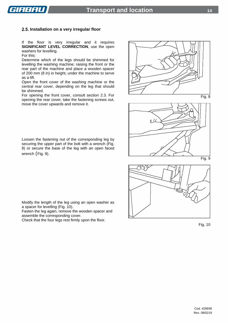
Installation on a very irregular floor
If the floor is very irregular and it requires SIGNIFICANT LEVEL CORRECTION, use the open washers for levelling. For this: Determine which of the legs should be shimmed for levelling the washing machine; raising the front or the rear part of the machine and place a wooden spacer of 200 mm (8 in) in height, under the machine to serve as a lift. Open the front cover of the washing machine or the central rear cover, depending on the leg that should be shimmed. For opening the front cover, consult section 2.3. For opening the rear cover, take the fastening screws out, move the cover upwards and remove it. Loosen the fastening nut of the corresponding leg by securing the upper part of the bolt with a wrench (Fig. 8) or secure the base of the leg with an open faced
wrench (Fig. 9). Modify the length of the leg using an open washer as a spacer for levelling (Fig. 10). Fasten the leg again, remove the wooden spacer and assemble the corresponding cover. Check that the four legs rest firmly upon the floor.
Fig. 8
Fig. 9
Fig. 10

Installation 15
Cod. 428938
Rev. 08/0219
3. INSTALLATION
ALL CONNECTIONS FOR ELECTRICAL POWER AND PLUMBING MUST COMPLY WITH THE STATUTORY SAFETY STANDARDS APPLICABLE TO EACH COUNTRY, AND BE MADE BY LICENSED INSTALLERS ONLY.
Gravity drain Drain to the drain box. (Most recommended option) Build a drain box following the specifications indicated in the INSTALLATION SPECS, section 1.4. Connect the drain elbow to the drain outlet and secure hose with the corresponding clamp (Fig. 11). It is recommended to not sink the free end of the drain elbow in the drain box:
To facilitate the water drain.
To detect water leaks through the drain
To prevent dirty water from coming into contact with the washer
Direct connection of the washer drain to the sewer (Fig. 12) Facilities preferring this option to the open box option (recommended option) must respect the following precautions:
Provide next to the connection point of each machine to the sewer, with a sewer ventilation pipe reaching the outside A, set at a height of 40 in. (1000 mm).
Create an anti-siphon system B to impede pressure variations and sewer backups before making the connection between the sewer drain and the general sewage system.
Fig. 12
Fig. 11
Installation 16
Cod. 428938
Rev. 08/0219
Fig. 13
f
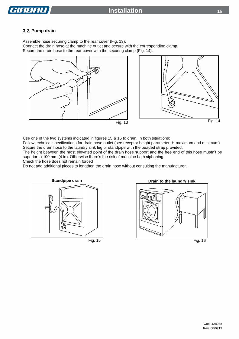
Pump drain
Assemble hose securing clamp to the rear cover (Fig. 13). Connect the drain hose at the machine outlet and secure with the corresponding clamp. Secure the drain hose to the rear cover with the securing clamp (Fig. 14).
Use one of the two systems indicated in figures 15 & 16 to drain. In both situations: Follow technical specifications for drain hose outlet (see receptor height parameter: H maximum and minimum) Secure the drain hose to the laundry sink leg or standpipe with the beaded strap provided. The height between the most elevated point of the drain hose support and the free end of this hose mustn’t be superior to 100 mm (4 in). Otherwise there’s the risk of machine bath siphoning. Check the hose does not remain forced Do not add additional pieces to lengthen the drain hose without consulting the manufacturer.
Fig. 14
Standpipe drain
Fig. 15
Drain to the laundry sink
Fig. 16

Installation 17
Cod. 428938
Rev. 08/0219
Water supply Hoses and pipes should be flushed through before being connected to the machine. Install at each water supply and in an accessible location, a mechanically interlocked water valve. Refer to technical specifications on the INSTALLATION SPECS, section 1.4. Arrangement of the hoses (Fig. 17) The inlets are identified by the label posted at each inlet. The washer mixes hot and cold water according to the temperature programmed. The use of hot/cold water allows the machine to gain time and effectiveness in its washing programs.
Inlet 1. The cold water must ALWAYS be connected. The hose is marked with a blue line.
Inlet 2. Connect hot water. This hose is marked with a red line.
Fig. 17
DO NOT CONNECT THE HOT WATER TO INLET 1. THIS INLET DOES NOT HAVE A TEMPERATURE CONTROL SYSTEM. INCOMPLIANCE OF THIS PRECAUTION CAN CAUSE FABRIC DAMAGE.
For a correct operation of the washing machine, the two water inlets must be supplied. If hot water supply is not available, connect cold water or cold softened water to inlet 2.
Assembling the connection couplings USA/CANADA (Fig. 18)
Insert seal B inside each of the water inlet couplings C.
Assemble the couplings to the electrovalves A.
Place water inlet hoses D in the electrovalves couplings. Open the manual valves and check for leaks in the
installation
Fig.18

Installation 18
Cod. 428938
Rev. 08/0219
Assembling the connection couplings for AUSTRALIA
IMPORTANT
20mm dual check valve supplied with machine must be installed on the cold water inlet to the machine. This valve is designed to prevent cross connection (back siphonage) and complies with AS/NZS Standard 2845.1 (Watermark).
Fit the non-return valve A to the cold water water inlet connection of the machine considering the flow direction marked on the valve.
Fit the coupling B downstream the valve.
Fit the water inlet hoses downstream the valve.
Fig. 19

Installation 19
Cod. 428938
Rev. 08/0219
Electrical connection. Permanently connected appliances. Permanently connected appliances are those that do not incorporate power cord from works. The electrical wiring of these machines is the responsibility of the installer and must comply with the indications of sections 3.4.1, 2 and 3. 1Ph 120V units supplied by the manufacturer with power cord, for USA/CANADA installations, are excluded from this group,
3.4.1. Previous requirements
CHECK THAT THE POWER AND FREQUENCY OF THE ELECTRICAL SUPPLY CORRESPONDS TO THOSE OF THE APPLIANCE. Check the nameplate posted on the back panel of the machine.
ALL CONNECTIONS FOR ELECTRICAL SUPPLY MUST BE CARRIED OUT BY LICENSED ELECTRICIANS AND MUST COMPLY WITH THE STATUTORY SAFETY STANDARDS APPLICABLE TO EACH COUNTRY.
ALL THE MATERIALS USED IN THE ELECTRICAL INSTALLATION MUST COMPLY WITH THE STATUTORY SAFETY STANDARDS APPLICABLE TO EACH COUNTRY.
ALWAYS CONNECT THE GROUND EXTERNAL PROTECTION CIRCUIT. THIS UNIT MUST BE CONNECTED TO THE GROUND INSTALLATION WITH A CONDUCTOR CONNECTED TO THE EQUIPMENT GROUNDING TERMINAL.
GIRBAU WASHING MACHINES HS-6008, EH020 ARE DESIGNED TO OPERATE IN SINGLE-PHASE AND THREE-PHASE LINES. MODELS OF VOLTAGE BETWEEN 380 AND 415 V REQUIRE IN ADDITION A CONNECTION TO THE NEUTRAL WIRE.
IN INSTALLATIONS WITH SEVERAL SINGLE-PHASE MACHINES CONNECTED BETWEEN PHASE AND NEUTRAL IN THREE-PHASE LINES, IT IS RECOMMENDED TO DISTRIBUTE THE CONNECTION BY USING THE THREE PHASES TO BALANCE THE CONSUMPTION OF ALL THE PHASES IN THE LINE.
Specific warning for appliances installed in USA/CANADA. This appliance must be connected to a grounded metal, permanent wiring system, or an equipment grounding conductor must be run with the circuit conductors and connected to the equipment grounding terminal on the appliance.
3.4.2. Installation characteristics. Before connecting the washer refer to INSTALLATION SPECIFICATIONS, section 1.4 and specific characteristics on the ELECTRICAL CONNECTION table, section 1.5. Conductor:
The data referring to conductors are based on those of multi-wire hose with copper conductor.
The length of the conductor from the safety switch to the washer must not be longer than 30ft (10 m).
For a correct fixation of the stuffing box to the washer inlet, the conductor must be of normalised hose and following the specifications on table section 1.5.
The conductor must be secured against any pulling, crushing or rubbing.
Additional specifications for the conductor: it must compy with the statutory regulations of the country in which it is to be installed.

Installation 20
Cod. 428938
Rev. 08/0219
Circuit breaker. Install an earth-leakage protected circuit breaker. Characteristics:
Installed in an easily accessible place.
number of poles and intensity: consult ELECTRICAL CONNECTION table (section 1.5)
A type.
protected against pulse currents, harmonics, the presence of continuous components... (consult manufacturer specifications)
Safety switch. Install an Automatic on/off Switch, outside the washer, with individual protection for each machine. Characteristics:
number of poles and intensity: consult ELECTRICAL CONNECTION table (section 1.5)
C type with top opening at 3 mm (0,12 in).
Must isolate electrical source phases and the N cable.
Mechanically lockable.
Installed in an easily accessible place.
3.4.3. Machine electrical connection
Disconnect and mechanically lock the external
automatic switch.
Open machine terminal box.
Fix the electrical supply hose to the stuffing box at the washer entry.
Connect the wires to the connection board.
The connection sequence of the cables to the entry board varies according to the number of phases and the voltage of the washer. On the label posted next to the entry board are indicated the different connection options. Refer to fig. 20.
Electrical connection. 1ph, 120V units with power cord (USA / CANADA only) These models, available only for USA/CANADA installations are supplied with power cord built-in the washer. Connection characteristics Connect to 15A mains outlet socket, Individual Branch Circuit. Do not use any adaptor or extension cord between plug and socket. GROUNDING INSTRUCTIONS This appliance must be grounded. In the event of malfunction or breakdown, grounding will reduce the risk of electric shock by providing a path of least resistance for electric current. This appliance is equipped with a cord having an equipment-grounding conductor and a grounding plug. The plug must be plugged into an appropriate outlet that is properly installed and grounded in accordance with all local codes and ordinances. CAUTION! Improper connection of the equipment-grounding conductor can result in a risk of electric shock. Check with a qualified electrician or serviceman if you are in doubt as to whether the appliance is properly grounded. Do not modify the plug provided with the appliance – if it will not fit the outlet, have a proper outlet installed by a qualified electrician.
Fig. 20

Installation 21
Cod. 428938
Rev. 08/0219
External dosing (option) This machine can control external dispenser equipment by generating a signal able to activate the various inlets of the dispenser equipment. These signals are made by closing a relay contact between the COMMON terminal and the outputs of each one of the various terminals coinciding with the different dosing made by the washing programs. The icons on the label indicate which output corresponds with each dispenser compartments. The length of the signal has a fixed time (between 20 and 30 sec.) and can not be modified. Consult electrical connection specifications in the INSTALLATION SPECS, section 1.4.
3.6.1. External dosing electrical connection Signal conductor
If using single-wire conductors, these must be encased within a safety conduit.
The conductor must be affixed to the inlet opening of the machine using a secure connection appropriate for the type of conductor.
The conductor must be protected against traction, crushing and friction.
Additional specifications for the conductor: it must compy with the statutory regulations of the country in which it is to be installed.
Connection of the dispenser equipment to the washer (Fig. 21)
Disconnect and mechanically lock the external automatic switch.
Open machine terminal box.
Place a mechanism (not supplied with the washer) to fasten the conductor to the drilled entry hole and fasten the conductor.
Connect the dispenser signal conductor to the terminal board A, according to the functions specified on the corresponding label. (This terminal board is identified on the electrical schematic as A-4)
Connect the electrical supply of the dispenser equipment to an electrical inlet separate from the washer. The electrical protection of the dispenser equipment must be separate from the washer protection.
NEVER CONNECT THE DISPENSER EQUIPMENT SUPPLY TO THE WASHER
3.6.2. External dosing hoses connection The external dispenser inlets are protected by a tube cap. To connect the product conduits: See the technical specifications section.
Locate the dosing inlets in the back of the machine.
Remove the tube caps and save them for connection for non-dosing in the future.
Connect the hoses to the nipples B on the manifold.
Fix the dosing hoses to the washing machine with the appropriate clamps. COIN CONTROL units: To enable the external dosing system, you must modify the external dosing parameter at the MODIFICATION menu (see the Operation Instructions, for HS-6 / EH COIN CONTROL).
Fig. 21

Installation 22
Cod. 428938
Rev. 08/0219
Tensioning belts
ATTENTION!
Excessive tightening will dramatically reduce the life of the motors and can cause breakage of the pulley or the shaft.
A belt that is too slack can lead to jerky movements and cause damage to the belt itself.
To check the tension of the belts, apply a force in the centre of the span of 5 kg (11 lb) and tighten until obtaining the values shown in the table below.
NEW BELTS
BELTS IN USE
HS-6008 EH020
11 mm (0,43 in) 15 mm (0,59 in)
Fig. 22

Installation 23
Cod. 428938
Rev. 08/0219
Initial Start-up
The washer must be put into service by an AUTHORIZED SERVICE TECHNICIAN.
Before the initial STARTING, make sure that you accomplish the following points:
Remove all packaging materials (Break them down in order to appropriately recycle them)
Remove all tools used during the installation.
Verify that all accessories have been removed from the drum interior.
Verify the correct installation of all the accessories necessary for the washer operation.
Check that the electrical installation corresponds with the voltage and the frequency of the machine.
Verify that the four washer feet come in contact with the floor.
Verify that all the shipping restraints are removed.
Connect all the water and power inlets according to the technical specifications.
Open the manual water inlet valves and check for any leaks around the manual flow valves and connection couplings.
Connect the electrical supply.
Check the operation (it is recommended to use the TEST program).
Keep the manual in a safe place and in good condition for its possible consultation.
Before washing clothes for the first time we recommend to run a complete cycle with detergent (1/4 the normal recommended amount).
Emergency stop in coin-op installations
IN ACCORDANCE WITH SAFETY REQUIREMENTS FOR INDUSTRIAL MACHINERY STANDARD (UNE-EN ISO 10472-1,5-2) AND OTHER SAFETY REQUIREMENTS, THE LAUNDRY OWNER/MANAGER IS RESPONSIBLE FOR INSTALLING AN EMERGENCY STOP DEVICE THAT AFFECTS ALL THE MACHINES IN THE LAUNDRY.
Device features
To be located in a visible place, separated from all machines and easily accessible.
To break the electrical supply for all machines.
To safely isolate all machines at maximum consumption.
To need reinstating (the whole installation) after the Emergency Stop Push-button has been released.

Installation 24
Cod. 428938
Rev. 08/0219
Wash cycle start-up from an external device to the washing machine
VERY IMPORTANT !!! Washing machine cycle start-up should only be started by voluntary activation using an actuating element designated for this purpose. For machines connected to a remote control start-up system (e.g. a central vending point, etc.), the control must be located so as to ensure that the operator may be absolutely certain that no person is exposed to any dangerous area of the washing machine (pursuant to Machine Directive 2006/42/CE, Annex 1).
3.10.1. Connecting to a central vending unit and configuring the machine
Consult the manual for INSTALLING AND CONFIGURING THE VENDING CIRCUIT part number 430731.