installation guide - fccid.io · this chapter describes the changes in the lampsite installation...
TRANSCRIPT

LampSite
Installation Guide
Issue 02
Date 2014-05-27
HUAWEI TECHNOLOGIES CO., LTD.

Copyright © Huawei Technologies Co., Ltd. 2014. All rights reserved.
No part of this document may be reproduced or transmitted in any form or by any means without prior writtenconsent of Huawei Technologies Co., Ltd. Trademarks and Permissions
and other Huawei trademarks are trademarks of Huawei Technologies Co., Ltd.All other trademarks and trade names mentioned in this document are the property of their respective holders. NoticeThe purchased products, services and features are stipulated by the contract made between Huawei and thecustomer. All or part of the products, services and features described in this document may not be within thepurchase scope or the usage scope. Unless otherwise specified in the contract, all statements, information,and recommendations in this document are provided "AS IS" without warranties, guarantees or representationsof any kind, either express or implied.
The information in this document is subject to change without notice. Every effort has been made in thepreparation of this document to ensure accuracy of the contents, but all statements, information, andrecommendations in this document do not constitute a warranty of any kind, express or implied.
Huawei Technologies Co., Ltd.Address: Huawei Industrial Base
Bantian, LonggangShenzhen 518129People's Republic of China
Website: http://www.huawei.com
Email: [email protected]
Issue 02 (2014-05-27) Huawei Proprietary and ConfidentialCopyright © Huawei Technologies Co., Ltd.
i

About This Document
OverviewThis document describes how to install the modules and cables for the RHUB3908 andpRRU3901 indoors. It also provides checklists for hardware installation.
Product VersionThe following table lists the product version related to this document.
Product Name Product Version
RHUB3908 (referred to as RHUB in thisdocument)
V100R009C00 and later versionsSingle-mode versions mappingV100R009C00:l NodeB: V200R016C00l eNodeB: V100R007C00
pRRU3901 (referred to as pRRU in thisdocument)
Intended AudienceThis document is intended for:l BTS installation personnel
LampSiteInstallation Guide About This Document
Issue 02 (2014-05-27) Huawei Proprietary and ConfidentialCopyright © Huawei Technologies Co., Ltd.
ii

Contents
About This Document.....................................................................................................................ii
1 Changes in LampSite Installation Guide.................................................................................1
2 Installation Preparations..............................................................................................................42.1 Reference Documents.....................................................................................................................................................52.2 Preparing Tools and Instruments....................................................................................................................................52.3 Requirements for Installation Personnel.........................................................................................................................6
3 Unpacking and Checking............................................................................................................7
4 Installing an RHUB.......................................................................................................................94.1 Information About the Installation...............................................................................................................................104.1.1 RHUB Installation Scenarios.....................................................................................................................................104.1.2 Installation Clearance Requirements of an RHUB....................................................................................................144.1.3 Installation Environment of an RHUB......................................................................................................................164.2 Installation Process.......................................................................................................................................................184.3 Installing an RHUB......................................................................................................................................................184.3.1 Installing an RHUB in a 19-Inch Cabinet or Rack....................................................................................................184.3.2 Installing an RHUB in a 19-Inch Shelf.....................................................................................................................214.3.3 Installing an RHUB on a Wall...................................................................................................................................244.4 Installing RHUB Cables...............................................................................................................................................284.4.1 Requirements for Cable Layout.................................................................................................................................284.4.2 RHUB Cable List.......................................................................................................................................................304.4.3 Cable Connections.....................................................................................................................................................324.4.4 RHUB Cable Installation Process..............................................................................................................................324.4.5 Installing an RHUB PGND Cable.............................................................................................................................334.4.6 Installing an Ethernet Cable......................................................................................................................................354.4.7 Installing CRPI Optical Cables..................................................................................................................................364.4.8 Installing an RHUB Alarm Cable (Optional)............................................................................................................384.4.9 Installing an RHUB Power Cable..............................................................................................................................394.5 Checking the RHUB Hardware Installation.................................................................................................................404.6 Power-on Check on an RHUB......................................................................................................................................42
5 Installing a pRRU........................................................................................................................44
LampSiteInstallation Guide Contents
Issue 02 (2014-05-27) Huawei Proprietary and ConfidentialCopyright © Huawei Technologies Co., Ltd.
iii

5.1 Information About the Installation...............................................................................................................................465.1.1 pRRU Product Family...............................................................................................................................................465.1.2 pRRU Installation Scenario.......................................................................................................................................465.1.3 Space Requirements..................................................................................................................................................505.1.4 pRRU Installation Environment Requirements.........................................................................................................535.2 Obtaining the MAC Address (Optional) .....................................................................................................................545.3 Installation Process.......................................................................................................................................................545.4 Installing a pRRU.........................................................................................................................................................555.4.1 pRRU Installation Kits..............................................................................................................................................565.4.2 pRRU Installed on a Wall..........................................................................................................................................575.4.3 pRRU Installed on a Ceiling......................................................................................................................................605.4.4 pRRU Installed on a Pole..........................................................................................................................................635.4.5 pRRU Installed on a Plate.........................................................................................................................................655.4.6 pRRU Installed on a Keel..........................................................................................................................................685.5 Installing the AC/DC Power Adapter (Optional).........................................................................................................715.6 Installing the Extender (Optional)................................................................................................................................755.7 Installing pRRU Cables................................................................................................................................................775.7.1 Cabling Requirements...............................................................................................................................................775.7.2 List of pRRU Cables..................................................................................................................................................785.7.3 Cable Connections.....................................................................................................................................................795.7.4 Cable Connections (LTE TDD).................................................................................................................................805.7.5 pRRU cable installation process................................................................................................................................825.7.6 Installing an Ethernet Cable......................................................................................................................................835.7.7 Installing pRRU Jumpers (Optional).........................................................................................................................845.7.8 Installing adapter power cables.................................................................................................................................865.8 Checking the pRRU Hardware Installation..................................................................................................................875.9 Powering on the pRRU.................................................................................................................................................88
6 Appendix.......................................................................................................................................906.1 MAC Collection Template...........................................................................................................................................916.2 Installing RF Daughter Boards on a pRRU (in Capacity Expansion Scenarios)..........................................................91
LampSiteInstallation Guide Contents
Issue 02 (2014-05-27) Huawei Proprietary and ConfidentialCopyright © Huawei Technologies Co., Ltd.
iv

1 Changes in LampSite Installation Guide
This chapter describes the changes in the LampSite Installation Guide.
02 (2014-05-27)
This is the second commercial release.
Compared with 01 (2014-04-26), no information is added.
Compared with 01 (2014-04-26), this issue incorporates the following change:
Content Change Description
Entire document Added the descriptions about the LTE FDD+LTE FDD mode.
Compared with 01 (2014-04-26), no information is deleted.
01 (2014-04-26)
This is the first commercial release.
Compared with Draft C (2014-03-26), no information is added.
Compared with Draft C (2014-03-26), this issue incorporates the following changes:
Content Change Description
Entire document Changed the pRRU name from pRRU withtwo Ethernet ports to pRRU with twotransmission ports, and pRRU with threeEthernet ports to pRRU with threetransmission ports.
Compared with Draft C (2014-03-26), no information is deleted.
LampSiteInstallation Guide 1 Changes in LampSite Installation Guide
Issue 02 (2014-05-27) Huawei Proprietary and ConfidentialCopyright © Huawei Technologies Co., Ltd.
1

Draft C (2014-03-26)
This is a draft release.
Compared with Draft B (2014-02-28), no information is added.
Compared with Draft B (2014-02-28), this issue incorporates the following changes:
Content Change Description
4.4.7 Installing CRPI Optical Cables Added the description of connecting theCPRI cable to the TX and RX ports of theoptical module crossly.
5.1.4 pRRU Installation EnvironmentRequirements
The operating temperature of pRRU isupdated.
Compared with Draft B (2014-02-28), no information is deleted.
Draft B (2014-02-28)
This is a draft release.
Compared with draft A (2013-11-30), this issue includes the following new topics:
l 5.2 Obtaining the MAC Address (Optional)l 5.7.3 Cable Connectionsl 6.1 MAC Collection Template
Compared with draft A (2013-11-30), this issue incorporates the following changes:
Content Change Description
Entire document Added descriptions about pRRUs with threetransmission ports. Such pRRUs supportintegrated Wi-Fi services.
Added the descriptions about the UMTS, LTEFDD and UMTS+LTE FDD mode.
About This Document Optimized descriptions about matchingproduct versions.
4.4.6 Installing an Ethernet Cable Changed the cable name from RHUB-pRRUEthernet cable to Ethernet cable.
5.7.6 Installing an Ethernet Cable
Compared with draft A (2013-11-30), this issue excludes the following topics:
l Installing External Antennas (Optional)
l RHUB Exterior
LampSiteInstallation Guide 1 Changes in LampSite Installation Guide
Issue 02 (2014-05-27) Huawei Proprietary and ConfidentialCopyright © Huawei Technologies Co., Ltd.
2

l RHUB Ports and Indicatorsl pRRU Exteriorl pRRU Ports and Indicators
Draft A (2013-11-30)This is a draft release.
LampSiteInstallation Guide 1 Changes in LampSite Installation Guide
Issue 02 (2014-05-27) Huawei Proprietary and ConfidentialCopyright © Huawei Technologies Co., Ltd.
3

2 Installation Preparations
About This Chapter
Before starting the installation, you must obtain the required reference documents, tools, andinstruments, and familiarize yourself with the skills required.
2.1 Reference DocumentsBefore the installation, you must read the following documents:
2.2 Preparing Tools and InstrumentsThis section describes the tools and instruments that must be prepared before the installation.
2.3 Requirements for Installation PersonnelThis section describes requirements for installation engineers. They must be qualified andtrained, and familiar with correct operation methods and safety precautions before performingany operations.
LampSiteInstallation Guide 2 Installation Preparations
Issue 02 (2014-05-27) Huawei Proprietary and ConfidentialCopyright © Huawei Technologies Co., Ltd.
4

2.1 Reference DocumentsBefore the installation, you must read the following documents:
l LampSite Hardware Descriptionl Installation Reference
For details about how to install a baseband unit (BBU), see DBS3900 Installation Guide.
2.2 Preparing Tools and InstrumentsThis section describes the tools and instruments that must be prepared before the installation.
Marker
Level
Torque screwdriver
(M4 to M6)
Diagonal pliers
Power cable crimping tool RJ11 crimping tool Cable cutter
Rubber mallet T20 torque torx screwdriver Wire stripper
Hammer drill (Ø6,Ø8 andØ12)
Torque wrench (Ø10 mm) Protective gloves
Guarded blade utility knife ESD gloves Long measuring tape
LampSiteInstallation Guide 2 Installation Preparations
Issue 02 (2014-05-27) Huawei Proprietary and ConfidentialCopyright © Huawei Technologies Co., Ltd.
5

Multimeter Network cable tester Vacuum cleaner
Ladder Torque wrench for SMAconnector
Socket wrench (M6)
2.3 Requirements for Installation PersonnelThis section describes requirements for installation engineers. They must be qualified andtrained, and familiar with correct operation methods and safety precautions before performingany operations.
Before the installation, pay attention to the following items:
l Technical engineers must take Huawei training and be familiar with proper installation andoperation methods.
l The number of installation personnel depends on the engineering schedule and installationenvironment. Generally, three to five persons are required. Generally, only three to fiveonsite personnel are necessary.
LampSiteInstallation Guide 2 Installation Preparations
Issue 02 (2014-05-27) Huawei Proprietary and ConfidentialCopyright © Huawei Technologies Co., Ltd.
6

3 Unpacking and Checking
This section describes how to unpack and check the delivered equipment to ensure that thematerials are complete and intact.
ContextNOTE
The following lists important notes when you are transporting, lifting, or installing the equipment orcomponents:
l Protect them from colliding with doors, walls, shelves, or other objects.
l Wear clean gloves and do not touch them with bare hands, sweat-soaked gloves, or dirty gloves.
NOTICEYou must power on the RHUB or pRRU within 7 days after it is unpacked.
Procedure
Step 1 Count the total number of the shipments.
If... Then...
The total number of the components isconsistent with that recorded in thepacking lists on all packing boxes
Go to Step 2.
The total number of the components isinconsistent with that recorded in thepacking lists on all packing boxes
Report the problems and causes to the localHuawei office.
Step 2 Check the exterior of each packing box.
LampSiteInstallation Guide 3 Unpacking and Checking
Issue 02 (2014-05-27) Huawei Proprietary and ConfidentialCopyright © Huawei Technologies Co., Ltd.
7

If... Then...
The exterior of each packing box is intact Go to Step 3.
It is damaged or soaked Report the problems and causes to the localHuawei office.
The collision label is red Do not unpack the packing box and claim forcompensation from the transportationcompany.
Step 3 Check the type and quantity of the equipment in the boxes according to the packing list.
If... Then...
The type and number are consistent withthe packing list on each packing list
Sign the Packing List with the operator.
There is any shortage, wrong delivery, ordamaged equipment
Report the problems and causes to the localHuawei office.
NOTICEPerform the following operations to protect the components from any damages and help findout the cause of any damage in future: 1. Store the unpacked equipment and packing materialsindoors. 2. Take photos of the storeroom, rusted or eroded equipment, packing box, and packingmaterials. 3. File the photos.
----End
LampSiteInstallation Guide 3 Unpacking and Checking
Issue 02 (2014-05-27) Huawei Proprietary and ConfidentialCopyright © Huawei Technologies Co., Ltd.
8

4 Installing an RHUB
About This Chapter
This chapter describes the process of installing an RHUB.
4.1 Information About the InstallationThis section describes the information to be learnt before RHUB installation, including theRHUB installation scenarios, clearance, and installation environment.
4.2 Installation ProcessThe RHUB installation involves installing an RHUB module, installing RHUB cables, checkingthe RHUB hardware installation, and powering on the RHUB.
4.3 Installing an RHUBAn RHUB can be installed in a cabinet, rack, shelf, or on a wall.
4.4 Installing RHUB CablesThis section describes how to install cables for an RHUB.
4.5 Checking the RHUB Hardware InstallationAfter an RHUB is installed, check the installation of hardware including the devices and relatedcables.
4.6 Power-on Check on an RHUBThis section describes the power-on check on the RHUB after the RHUB hardware is installedand checked.
LampSiteInstallation Guide 4 Installing an RHUB
Issue 02 (2014-05-27) Huawei Proprietary and ConfidentialCopyright © Huawei Technologies Co., Ltd.
9
4.1 Information About the InstallationThis section describes the information to be learnt before RHUB installation, including theRHUB installation scenarios, clearance, and installation environment.
4.1.1 RHUB Installation ScenariosAn RHUB can be installed in a 19-inch cabinet, rack, shelf, or on a wall.
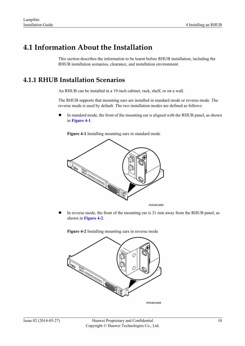
The RHUB supports that mounting ears are installed in standard mode or reverse mode. Thereverse mode is used by default. The two installation modes are defined as follows:
l In standard mode, the front of the mounting ear is aligned with the RHUB panel, as shownin Figure 4-1.
Figure 4-1 Installing mounting ears in standard mode
l In reverse mode, the front of the mounting ear is 31 mm away from the RHUB panel, asshown in Figure 4-2.
Figure 4-2 Installing mounting ears in reverse mode
LampSiteInstallation Guide 4 Installing an RHUB
Issue 02 (2014-05-27) Huawei Proprietary and ConfidentialCopyright © Huawei Technologies Co., Ltd.
10

Installing an RHUB in a 19-Inch Cabinet or RackInstalling an RHUB in a 19-inch cabinet or rack: Secure the mounting ear to the mounting bracketby using M6 screws.l If there is no other modules installed in the 1 U space near the RHUB, install the RHUB
directly. Otherwise, remove the modules before installing the RHUB.l Before installation, you need to check the installation mode supported by the rack and adjust
the position of the mounting ear.
Figure 4-3 and Figure 4-4 show RHUBs installed in a cabinet or rack, respectively.
Figure 4-3 Installing an RHUB in a 19-inch cabinet or rack in standard mode
Figure 4-4 Installing an RHUB in a 19-inch cabinet in reverse mode
Installing an RHUB in a 19-Inch ShelfWhen an RHUB is installed in a 19-inch shelf, the shelf must be installed on a wall. One shelfcan house multiple RHUBs with 1 U space between two RHUBs.
LampSiteInstallation Guide 4 Installing an RHUB
Issue 02 (2014-05-27) Huawei Proprietary and ConfidentialCopyright © Huawei Technologies Co., Ltd.
11

Figure 4-5 and Figure 4-6 show RHUBs installed in a 19-inch shelf.
Figure 4-5 RHUB installed in a 19-inch shelf in standard mode
LampSiteInstallation Guide 4 Installing an RHUB
Issue 02 (2014-05-27) Huawei Proprietary and ConfidentialCopyright © Huawei Technologies Co., Ltd.
12

Figure 4-6 RHUB installed in a 19-inch shelf in reverse mode
Installing an RHUB on a WallFigure 4-7 shows an RHUB installed on a wall.
LampSiteInstallation Guide 4 Installing an RHUB
Issue 02 (2014-05-27) Huawei Proprietary and ConfidentialCopyright © Huawei Technologies Co., Ltd.
13

Figure 4-7 RHUB installed on a wall
4.1.2 Installation Clearance Requirements of an RHUBWhen an RHUB is installed in a 19-inch cabinet, rack, shelf, or on a wall, a minimum clearanceis required for easy cabling and operation and maintenance. A recommended installationclearance is provided based on experience.
Figure 4-8 shows the installation clearance for the RHUB installed in a 19-inch cabinet, rack,or shelf.
Figure 4-8 Installation clearance for an RHUB installed in a 19-inch cabinet, rack, or shelf
Figure 4-9 and Figure 4-10 shows the recommended and minimum installation clearancerespectively when the RHUB is installed on a wall.
LampSiteInstallation Guide 4 Installing an RHUB
Issue 02 (2014-05-27) Huawei Proprietary and ConfidentialCopyright © Huawei Technologies Co., Ltd.
14

Figure 4-9 Recommended installation clearance for a wall-mounted RHUB (unit: mm)
LampSiteInstallation Guide 4 Installing an RHUB
Issue 02 (2014-05-27) Huawei Proprietary and ConfidentialCopyright © Huawei Technologies Co., Ltd.
15

Figure 4-10 Minimum installation clearance for a wall-mounted RHUB (unit: mm)
NOTICEA clearance of 350 mm must be reserved in front of the air inlet of the fan of the power supplyunit (PSU) for maintenance.
4.1.3 Installation Environment of an RHUBThe installation environment of an RHUB involves the running environment specifications forthe RHUB and other specifications.
RHUB Running Environment Specifications
Table 4-1 shows the environment specifications for the RHUB installed indoors.
l The temperature and humidity of the installation position must ensure normal operation. Acool and ventilated place is recommended.
l The heat dissipation holes on the RHUB cannot be blocked.
LampSiteInstallation Guide 4 Installing an RHUB
Issue 02 (2014-05-27) Huawei Proprietary and ConfidentialCopyright © Huawei Technologies Co., Ltd.
16

Table 4-1 RHUB environment specifications
Specifications
InstallationScenario
RHUBQuantity
Condition Remarks
Operatingtemperature
Installed on awall or in a 19-inch rack.
N/A -5°C to +50°C
N/A
Installed in ashelf.
1 -5°C to +45°C
N/A
2 -5°C to +43°C
N/A
3 -5°C to +40°C
N/A
Relativehumidity
Installed in allscenarios.
N/A 5% RH to95% RH
N/A
Altitude N/A N/A -60 m to+1800 m
Works properly.
1800 m to4000 m
Above the 1800 m altitude,the maximum operatingtemperature decreases by 1°Ceach time the altitudeincreases by 220 m.
NOTE
Installing more than one RHUB, 1 U space is required between two RHUBs.
Other Running Environment Specificationsl The RHUB cannot be installed at an air outlet of the heat dissipation box of an air
conditioner or other heat-generating appliances.
l The RHUB cannot be installed near a strong heat source.
l The RHUB cannot be installed in a position with water dripping, such as outdoor equipmentof air conditioners, pipe, and leaking or dripping roofs.
l The installation position must be far from rains. If the RHUB is installed on a wall, theremust be no window on either side of the wall.
l The installation position must be far away from high voltage, highly corrosive devices,flammable or explosive substances, and electromagnetic interference.
l The RHUB must be installed in a dry, ventilating, and dust-proof place.
l If the RHUB is installed in parking areas or basements, the installation position must bewell-ventilated.
LampSiteInstallation Guide 4 Installing an RHUB
Issue 02 (2014-05-27) Huawei Proprietary and ConfidentialCopyright © Huawei Technologies Co., Ltd.
17

4.2 Installation ProcessThe RHUB installation involves installing an RHUB module, installing RHUB cables, checkingthe RHUB hardware installation, and powering on the RHUB.
Figure 4-11 shows the RHUB installation process.
Figure 4-11 RHUB installation process
4.3 Installing an RHUBAn RHUB can be installed in a cabinet, rack, shelf, or on a wall.
4.3.1 Installing an RHUB in a 19-Inch Cabinet or RackThis section describes how to install an RHUB in a 19-inch cabinet.
Procedurel The following describes how to install an RHUB with mounting ears in reverse mode:
NOTE
If necessary, request one more person for assistance.
1. With one hand holding it, align the mounting holes with the installation holes, slowlypush the RHUB into the required position in the cabinet, as shown in Figure 4-12.
LampSiteInstallation Guide 4 Installing an RHUB
Issue 02 (2014-05-27) Huawei Proprietary and ConfidentialCopyright © Huawei Technologies Co., Ltd.
18

Figure 4-12 Pushing an RHUB into a cabinet
2. Use a torque screwdriver or Phillips screwdriver to tighten the four M6×16 screwswith a torque of 2 N•m, as shown in Figure 4-13.
Figure 4-13 Tightening screws
l The following describes how to install an RHUB with mounting ears aligned with theRHUB panel:
NOTE
If necessary, request one more person for assistance.
1. Remove the mounting ears on both sides of the RHUB by removing the four M4×8screws, as shown in Figure 4-14.
LampSiteInstallation Guide 4 Installing an RHUB
Issue 02 (2014-05-27) Huawei Proprietary and ConfidentialCopyright © Huawei Technologies Co., Ltd.
19

Figure 4-14 Removing mounting ears and screws
2. Use a torque screwdriver or Phillips screwdriver to tighten the four M4×8 screws witha torque of 1.4 N•m to install the removed mounting ears again, as shown in Figure4-15. The mounting ears must be aligned with the RHUB panel.
Figure 4-15 Installing mounting ears in standard mode
3. With one hand holding it, align the mounting holes with the installation holes, slowlypush the RHUB into the required position in the cabinet, as shown in Figure 4-16.
LampSiteInstallation Guide 4 Installing an RHUB
Issue 02 (2014-05-27) Huawei Proprietary and ConfidentialCopyright © Huawei Technologies Co., Ltd.
20

Figure 4-16 Pushing an RHUB into a cabinet
4. Use a torque screwdriver or Phillips screwdriver to tighten the four M6×16 screwswith a torque of 2 N•m, as shown in Figure 4-17.
Figure 4-17 Tightening screws
----End
4.3.2 Installing an RHUB in a 19-Inch ShelfIf a shelf houses more than one RHUB, 1 U space is required between two RHUBs. The PSUmust be installed at the bottom of the cabinet.
Procedurel The following describes how to install an RHUB with mounting ears installed in reverse
mode:
NOTE
If necessary, request one more person for assistance.
LampSiteInstallation Guide 4 Installing an RHUB
Issue 02 (2014-05-27) Huawei Proprietary and ConfidentialCopyright © Huawei Technologies Co., Ltd.
21

1. With one hand holding it, align the mounting holes with the installation holes, slowlypush the RHUB into the required position in the shelf.
2. Use a torque screwdriver or Phillips screwdriver to tighten the four M6×16 screwswith a torque of 2 N•m, as shown in Figure 4-18.
Figure 4-18 Tightening screws
l The following describes how to install an RHUB with mounting ears installed in standardmode:
NOTE
If necessary, request one more person for assistance.
1. Remove the mounting ears on both sides of the RHUB by removing the four M4×8screws, as shown in Figure 4-19.
LampSiteInstallation Guide 4 Installing an RHUB
Issue 02 (2014-05-27) Huawei Proprietary and ConfidentialCopyright © Huawei Technologies Co., Ltd.
22

Figure 4-19 Removing mounting ears and screws
2. Use a torque screwdriver or Phillips screwdriver to tighten the four M4×8 screws witha torque of 1.4 N•m to install the removed mounting ears again, as shown in Figure4-20. The mounting ears must be aligned with the RHUB panel.
Figure 4-20 Installing mounting ears in standard mode
3. With one hand holding it, align the mounting holes with the installation holes, slowlypush the RHUB into the required position in the cabinet, as shown in .
4. Use a torque screwdriver or Phillips screwdriver to tighten the four M6×16 screwswith a torque of 2 N•m, as shown in Figure 4-21.
LampSiteInstallation Guide 4 Installing an RHUB
Issue 02 (2014-05-27) Huawei Proprietary and ConfidentialCopyright © Huawei Technologies Co., Ltd.
23

Figure 4-21 Tightening screws
----End
4.3.3 Installing an RHUB on a WallAn RHUB can be installed on a wall.
Procedure
Step 1 The mounting ears are installed in reverse mode by default. Before installing an RHUB on awall, modify the installation mode of the mounting ears on the RHUB.l Use a torque screwdriver or Phillips screwdriver to remove the mounting ears on both sides
of the RHUB by removing the four M4×8 screws, as shown in Figure 4-22.
LampSiteInstallation Guide 4 Installing an RHUB
Issue 02 (2014-05-27) Huawei Proprietary and ConfidentialCopyright © Huawei Technologies Co., Ltd.
24

Figure 4-22 Removing screws and mounting ears
l Rotate the mounting ears 90 degrees clockwise, and use a torque screwdriver or Phillipsscrewdriver to secure the mounting ear with a torque of 1.4 N•m, as shown in Figure 4-23.
Figure 4-23 Installing mounting ears and screws
Step 2 Determine the position on the wall for installing the RHUB based on the requirements in theengineering blueprint and 4.1.2 Installation Clearance Requirements of an RHUB. Place theRHUB to the position to be installed against the wall, and then mark the four anchor points wherethe mounting ear screws are fastened using a marker, as shown in Figure 4-24.
LampSiteInstallation Guide 4 Installing an RHUB
Issue 02 (2014-05-27) Huawei Proprietary and ConfidentialCopyright © Huawei Technologies Co., Ltd.
25

Figure 4-24 Anchor points for installing an RHUB on a wall
(1) Level (2) RHUB (3) Wall
CAUTIONTo prevent inhalation or eye contact with dust, take adequate preventive measures when drillingholes.
Step 3 Drill holes at the anchor point and install expansion bolts, as shown in Figure 4-25.
LampSiteInstallation Guide 4 Installing an RHUB
Issue 02 (2014-05-27) Huawei Proprietary and ConfidentialCopyright © Huawei Technologies Co., Ltd.
26

Figure 4-25 Drilling holes and installing expansion bolts
(1) M6×60expansion bolt
(2) Nut (3) Spring washer (4) Flat washer (5) Extension tub
1. Use a hammer drill with bit 8 to drill holes with a diameter of 8 mm and a depth of 45 mmto 50 mm at the marked anchor points. All the holes have the same depth.
2. Use a vacuum cleaner to clear the dust inside and around each hole. If the distance betweentwo holes is incorrect, mark and drill holes again.
3. Partially tighten an expansion bolt and place it vertically into each hole.4. Use a rubber mallet to hit the expansion bolt until the entire expansion sleeve is in the hole.5. Remove the M6×60 bolt, nut, spring washer, and flat washer from each expansion bolt in
sequence.
NOTICEAfter removing an expansion bolt, ensure that the top of the expansion sleeve is level withthe wall. If it is not level, the RHUB cannot be installed on the concrete floor evenly andsecurely.
Step 4 Align the mounting holes with the four M6×60 expansion bolts. Install spring washer 6 and flatwasher 6 in sequence on each M6×60 expansion bolt, insert the bolts to each expansion tub, andthen use a torque wrench or socket wrench to tighten the four M6×60 bolts with a torque of 5N•m to secure the RHUB to the wall, as shown in Figure 4-26.
LampSiteInstallation Guide 4 Installing an RHUB
Issue 02 (2014-05-27) Huawei Proprietary and ConfidentialCopyright © Huawei Technologies Co., Ltd.
27

Figure 4-26 Installing an RHUB on a wall
NOTE
As shown in the preceding figure, when the RHUB is placed against the wall, ensure that the RHUB panelis vertical to the ground and the PSU is on the lower part of the RHUB panel.
----End
4.4 Installing RHUB CablesThis section describes how to install cables for an RHUB.
4.4.1 Requirements for Cable LayoutCables must be routed according to the specified cabling requirements to prevent signalinterference.
NOTE
If a cable listed below is not required, skip the requirements for routing the cable.
General Requirements for Cable LayoutBending radius
LampSiteInstallation Guide 4 Installing an RHUB
Issue 02 (2014-05-27) Huawei Proprietary and ConfidentialCopyright © Huawei Technologies Co., Ltd.
28

l The bending radius of the 7/8" feeder and 5/4" feeder are greater than 250 mm and 380mm, respectively.
l The bending radius of the 1/4'' jumper, the 1/2'' softer jumper, and the 1/2'' common jumperare greater than 35 mm, 50 mm, and 127 mm, respectively.
l The bending radius of a power cable or a protection ground (PGND) cable is at least threetimes the diameter of the cable.
l The bending radius of an optical cable is at least 20 times the diameter of the optical cable,and the minimum bending radius of the branch at each end of the optical cable is 30 mm.
l The bending radius of an E1/T1 cable is at least three times the diameter of the cable.
l The bending radius of an E1/T1 cable is at least five times the diameter of the cable.
Cable Bindingl Cables of the same type are bound together.
l Different types of cables must be separately routed with a minimum spacing of 30 mm andcannot be entangled or crossed.
l The cables are bound tightly and neatly and the cable sheath is intact.
l The cable ties face the same direction and all cable ties bound at similar positions must bein a straight line.
l The extra length of each indoor cable tie must be cut off. A slack of 5 mm is reserved foreach outdoor cable tie. All cut surfaces have no sharp edges.
l Labels or nameplates are attached to both ends, joints, or turns of cables after they areinstalled.
Safetyl Cables are placed away from sharp objects or wall burrs. If these positions are inevitable,
protection pipes are required for the cables.
l Cables are routed away from heat sources, or heat-insulation materials are added betweencables and heat sources.
l A clearance is reserved at turns of a cable or the position close to a device, facilitating cableand device maintenance. The recommended clearance is about 0.1 m.
Requirements for Special Cables
Power cablel Positions for routing power cables meet requirements of the engineering design.
l If the length of a power cable is insufficient, the cable is replaced with a new one and nojoint or solder joint is allowed on the original cable.
l Cables are routed only by qualified and trained personnel before all preparations are made.
l Cables are routed in an untangled and orderly fashion.
l If DC power cables need to be routed on the tower platform, the cables are routed alongthe inner side of the guard rail and the distance between the guard rail and the cable is short.
l If DC power cables need to be routed close to a device on the tower, the cables are securedto the guard rail or pole with cable clips and the device cannot be far away from the positionfor securing the cables.
PGND cable
LampSiteInstallation Guide 4 Installing an RHUB
Issue 02 (2014-05-27) Huawei Proprietary and ConfidentialCopyright © Huawei Technologies Co., Ltd.
29

l PGND cables for a base station are connected to the same ground bar.l PGND cables are buried in the ground or routed indoors. They cannot be routed overhead
before they are routed into the equipment room.l Outer conductors of coaxial cables and both ends of the shield layers on shielded cables
are in proper electrical contact with the metal surface of the equipment to which they areconnected.
l PGND cables and signal cables are installed in an untangled and orderly fashion. A certaindistance is reserved between them to prevent interference from each other.
l Fuses or switches are not allowed on PGND cables.l Other devices cannot be used for electrical connections of PGND cables.l All the metal parts in the equipment are reliably connected to the ground terminal.
Optical cablel A minimum of three qualified or trained personnel are required to route optical cables.l The ambient temperature for optical cables ranges from -40°C to +60°C. If the actual
temperature is not within the range, preventive measures are taken or a new cabling routeis required.
l Cables are routed in an untangled and orderly fashion.l Optical fibers cannot be bound at turns.l Optical fibers cannot be stretched with too much force or stepped on, and they are far away
from sharp objects. Heavy objects cannot be placed on optical cables.l When optical cables are routed, the extra length of the cables is coiled around special
devices, such as a fiber coiler.l Even strength is applied when optical cables are coiled and optical cables cannot be bent
in a forcible manner.l Vacant optical connectors are covered with dust-proof caps.l If optical cables need to be routed on the tower platform, the optical cables are routed along
the inner side of the guard rail and the distance between the guard rail and the cable is theshortest one.
l If optical cables need to be routed close to a device on the tower, the optical cables aresecured to the guard rail or pole with cable clips and the device cannot be far away fromthe position for securing the optical cables.
l If the optical cable close to a device on the tower is too long, the optical cables are wrappedand secured to the tower.
4.4.2 RHUB Cable ListThis section describes the connector types and connections of the RHUB cables.
Table 4-2 lists RHUB cables.
LampSiteInstallation Guide 4 Installing an RHUB
Issue 02 (2014-05-27) Huawei Proprietary and ConfidentialCopyright © Huawei Technologies Co., Ltd.
30

Table 4-2 RHUB cable list
Cable One End The Other End
Connector Connectedto...
Connector Connected to...
PGND cable OT terminal (M4,6 mm2 [0.009 in.2])
Ground screwson the RHUB
OT terminal(M6, 6 mm2
[0.009 in.2])
Ground terminalon the externalground bar
RHUB powersupply cable
C13 femaleconnector
AC powerinput socket onthe RHUB
3-pin connector External powerinput socket
CPRI opticalfiber
DLC connector CPRI port onthe LBBP,WBBP orUBBP in theBBU
DLC connector CPRI0 or CPRI1port on the RHUB
CPRI0 orCPRI1 port onthe RHUB
DLC connector CPRI0 or CPRI1port on the RHUB
CPRI port onthe LBBP,WBBP orUBBP in theBBU
FC connector,SC connector, orLC connector
ODF
CPRI0 orCPRI1 port onthe RHUB
FC connector,SC connector, orLC connector
ODF
Ethernetcable
RJ45 connector CPRI_E0~CPRI_E7 port onthe RHUB
RJ45 connector CPRI_E0~CPRI_E1 port on thepRRU
(Optional)RHUB alarmcable
RJ45 connector EXT_ALMport on theRHUB
Bare end Alarm signal portof the backuppower system
NOTE
l If one end of the CPRI cable is connected to the DLC connector, the other end connects the BBU, orRHUB through the DLC connector. If one end of the CPRI cable is connected to the ODF adapter, theother end connects the BBU or RHUB through a connector corresponding to the adapter. The connectorsinclude the FC connector, SC connector, and LC connector.
l The Extender can be used to lengthen the distance between the RHUB and the pRRU connected usingthe Ethernet cable. If the Extender is used, the Ethernet cable is divided into two parts, one betweenthe RHUB and the Extender and the other between the Extender and the pRRU.
LampSiteInstallation Guide 4 Installing an RHUB
Issue 02 (2014-05-27) Huawei Proprietary and ConfidentialCopyright © Huawei Technologies Co., Ltd.
31

4.4.3 Cable ConnectionsThis section describes the cable connections for an RHUB.
Figure 4-27 shows the cable connections for an RHUB. The port connected to the Ethernetswitch serves as a reserved port.
Figure 4-27 Cable connections for an RHUB
(1) CPRI optical cable (2) Ethernet cable (3)RHUB alarm cable
(4) RHUB power cable (5) PGND cable -
NOTE
The Extender can be used to lengthen the distance between the RHUB and the pRRU connected using theEthernet cable. If the Extender is used, the Ethernet cable is divided into two parts, one between the RHUBand the Extender and the other between the Extender and the pRRU.
4.4.4 RHUB Cable Installation ProcessThis section describes the process of installing RHUB cables.
Figure 4-28 shows the RHUB cable installation process.
LampSiteInstallation Guide 4 Installing an RHUB
Issue 02 (2014-05-27) Huawei Proprietary and ConfidentialCopyright © Huawei Technologies Co., Ltd.
32

Figure 4-28 RHUB cable installation process
4.4.5 Installing an RHUB PGND CableAn RHUB PGND cable ensures proper grounding of an RHUB.
PrerequisitesThe OT terminals at both ends of the PGND cable are prepared.
Context
The yellow and green or green PGND cable is a single cable. The cross-sectional area of thePGND cable is 6 mm2 (0.009 in.2). Both ends of the cable are OT terminals, as shown in Figure1.
Figure 4-29 Exterior of a PGND cable
(1) OT terminal (6 mm2 [0.009 in.2], M4) (2) OT terminal (6 mm2 [0.009 in.2], M6)
LampSiteInstallation Guide 4 Installing an RHUB
Issue 02 (2014-05-27) Huawei Proprietary and ConfidentialCopyright © Huawei Technologies Co., Ltd.
33

NOTE
l If the PGND cable is provided by the customer, a copper-core cable with a minimum cross-sectionalarea of 6 mm2 (0.009 in.2) or 10 AWG is recommended.
l The OT terminals at both ends of the PGND cable are assembled at the site.
l The M6 OT terminal has the default size. You can replace it with another OT terminal of the expectedsize based on the site requirement.
NOTICEl Ensure proper grounding of the RHUB using a PGND cable.l When installing the PGND cable, tightly press the OT terminal in the correct direction, as
shown in Figure 4-30.
Figure 4-30 Correct direction of an OT terminal for the PGND cable
Procedure
Step 1 Route the PGND cable by referring to 4.4.1 Requirements for Cable Layout.
Step 2 Use a torque screwdriver or Phillips screwdriver to secure the M4 OT terminal at one end of thePGND cable to the ground screw on the RHUB panel with a torque of 1.4 N•m. If the OT terminalis a one-hole OT terminal, connect it to the ground screw on the lower part of the RHUB panel,as shown in Figure 4-31.
LampSiteInstallation Guide 4 Installing an RHUB
Issue 02 (2014-05-27) Huawei Proprietary and ConfidentialCopyright © Huawei Technologies Co., Ltd.
34
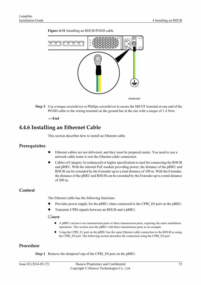
Figure 4-31 Installing an RHUB PGND cable
Step 3 Use a torque screwdriver or Phillips screwdriver to secure the M8 OT terminal at one end of thePGND cable to the wiring terminal on the ground bar at the site with a torque of 1.4 N•m.
----End
4.4.6 Installing an Ethernet CableThis section describes how to install an Ethernet cable.
Prerequisitesl Ethernet cables are not delivered, and they must be prepared onsite. You need to use a
network cable tester to test the Ethernet cable connection.l Cables of Category 5e (enhanced) or higher specification is used for connecting the RHUB
and pRRU. With the internal PoE module providing power, the distance of the pRRU andRHUB can be extended by the Extender up to a total distance of 100 m. With the Extender,the distance of the pRRU and RHUB can be extended by the Extender up to a total distanceof 200 m.
ContextThe Ethernet cable has the following functions:l Provides power supply for the pRRU when connected to the CPRI_E0 port on the pRRU.l Transmits CPRI signals between an RHUB and a pRRU.
NOTE
l A pRRU can have two transmission ports or three transmission ports, requiring the same installationoperations. This section uses the pRRU with three transmission ports as an example.
l Using the CPRI_E1 port on the pRRU has the same Ethernet cable connection to the RHUB as usingthe CPRI_E0 port. The following section describes the connection using the CPRI_E0 port.
Procedure
Step 1 Remove the dustproof cap of the CPRI_E0 port on the pRRU.
LampSiteInstallation Guide 4 Installing an RHUB
Issue 02 (2014-05-27) Huawei Proprietary and ConfidentialCopyright © Huawei Technologies Co., Ltd.
35
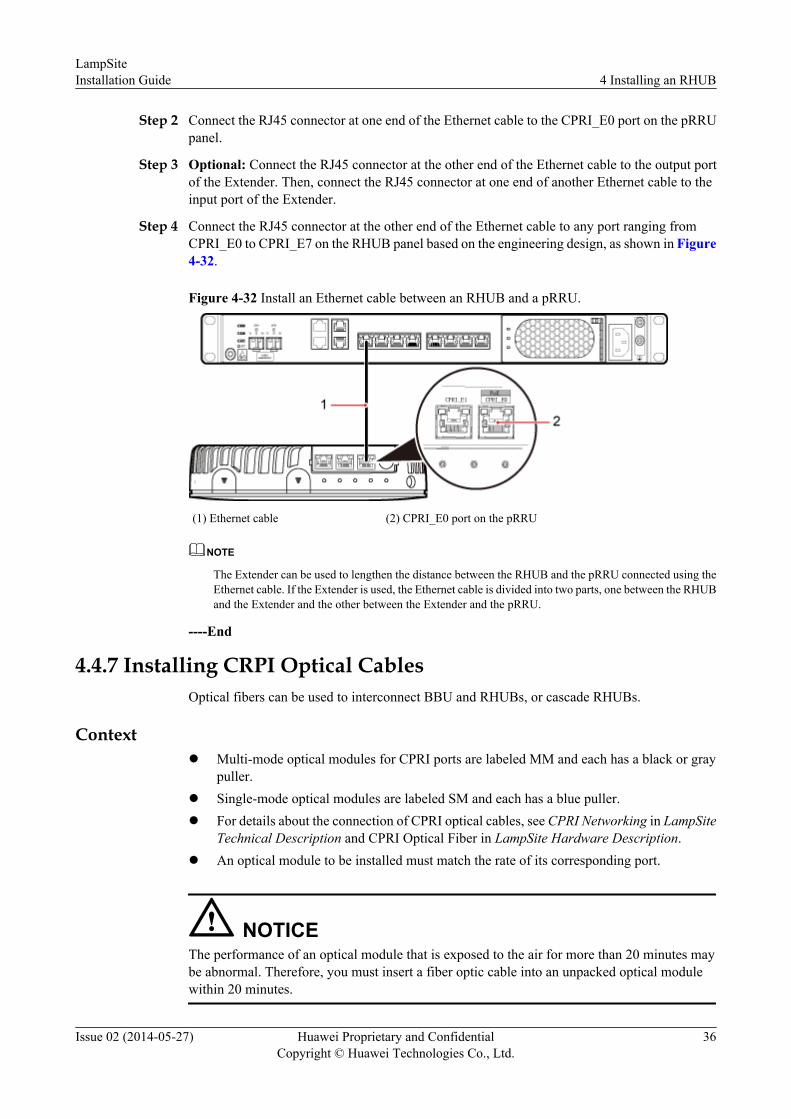
Step 2 Connect the RJ45 connector at one end of the Ethernet cable to the CPRI_E0 port on the pRRUpanel.
Step 3 Optional: Connect the RJ45 connector at the other end of the Ethernet cable to the output portof the Extender. Then, connect the RJ45 connector at one end of another Ethernet cable to theinput port of the Extender.
Step 4 Connect the RJ45 connector at the other end of the Ethernet cable to any port ranging fromCPRI_E0 to CPRI_E7 on the RHUB panel based on the engineering design, as shown in Figure4-32.
Figure 4-32 Install an Ethernet cable between an RHUB and a pRRU.
(1) Ethernet cable (2) CPRI_E0 port on the pRRU
NOTE
The Extender can be used to lengthen the distance between the RHUB and the pRRU connected using theEthernet cable. If the Extender is used, the Ethernet cable is divided into two parts, one between the RHUBand the Extender and the other between the Extender and the pRRU.
----End
4.4.7 Installing CRPI Optical CablesOptical fibers can be used to interconnect BBU and RHUBs, or cascade RHUBs.
Contextl Multi-mode optical modules for CPRI ports are labeled MM and each has a black or gray
puller.l Single-mode optical modules are labeled SM and each has a blue puller.l For details about the connection of CPRI optical cables, see CPRI Networking in LampSite
Technical Description and CPRI Optical Fiber in LampSite Hardware Description.l An optical module to be installed must match the rate of its corresponding port.
NOTICEThe performance of an optical module that is exposed to the air for more than 20 minutes maybe abnormal. Therefore, you must insert a fiber optic cable into an unpacked optical modulewithin 20 minutes.
LampSiteInstallation Guide 4 Installing an RHUB
Issue 02 (2014-05-27) Huawei Proprietary and ConfidentialCopyright © Huawei Technologies Co., Ltd.
36

Procedure
Step 1 Install an optical module, as shown in Figure 4-33 and Figure 4-34.
1. Remove the dust-proof cap from the CPRI port on the RHUB panel.
2. Remove the dust-proof cap on the optical module.
3. Lower the puller of the optical module.
4. Insert the optical module into the CPRI port on the RHUB, BBU or ODF.
5. Raise the puller of the optical module.
Figure 4-33 Removing the dust-proof cap from a port
Figure 4-34 Installing an optical module
Step 2 Install a CPRI optical cable, as shown in Figure 4-35.
1. Remove the dust-proof cap from the optical cable connector.
2. Install the optical cables by referring to Table 4-3.
Table 4-3 CPRI optical cable connections
One End The Other End
Connector
Connected to Connector Connected to
DLCconnector
BBU/LBBP&WBBP&UBBP/CPRI port
DLC connector CPRI0 or CPRI1 port onthe RHUB
CPRI0 or CPRI1 port on theRHUB
CPRI0 or CPRI1 port onthe RHUB
LampSiteInstallation Guide 4 Installing an RHUB
Issue 02 (2014-05-27) Huawei Proprietary and ConfidentialCopyright © Huawei Technologies Co., Ltd.
37

One End The Other End
Connector
Connected to Connector Connected to
BBU/LBBP&WBBP&UBBP/CPRI port
FC, SC, or LCconnector
ODF
CPRI0 or CPRI1 port on theRHUB
NOTE
l If one end of the CPRI cable is connected to the DLC connector, the other end connects the BBU orRHUB through the DLC connector. If one end of the CPRI cable is connected to the ODF adapter, theother end connects the BBU or RHUB through a connector corresponding to the adapter. The connectorsinclude the FC connector, SC connector, and LC connector.
l When connecting the CPRI cable to the TX and RX ports of the optical module through connectors ina cross manner, ensure that one end of a core of the CPRI cable is connected to the TX port and theother end is connected to the RX port. Figure 4-35 shows how to install a CPRI optical cable forconnecting the BBU and RHUBs.
Figure 4-35 Installing an CRPI optical cable
Step 3 Route the cable, and then use a cable tie to bind the cable. For details, see 4.4.1 Requirementsfor Cable Layout.
Step 4 Label the installed cable. For details, see section Attaching an L-Shaped Label in the InstallationReference.
----End
4.4.8 Installing an RHUB Alarm Cable (Optional)An RHUB alarm cable transmits dry node alarm signals.
LampSiteInstallation Guide 4 Installing an RHUB
Issue 02 (2014-05-27) Huawei Proprietary and ConfidentialCopyright © Huawei Technologies Co., Ltd.
38

PrerequisitesConnectors for an alarm cable are prepared.
ContextFigure 4-36 shows the exterior of an RHUB alarm cable. 4.4.2 RHUB Cable List shows theinstallation position on both ends of the RHUB cable.
Figure 4-36 RHUB alarm cable
Procedure
Step 1 Connect the RJ45 connector on one end of the alarm cable to the EXT_ALM port on the RHUB.
Step 2 Connect the other end of the alarm cable to the alarm cable port on the device to be monitored.
----End
4.4.9 Installing an RHUB Power CableThe RHUB power cable provides 110 V AC/220 V AC power supply for the RHUB.
Procedure
Step 1 Route the power cable by referring to 4.4.1 Requirements for Cable Layout.
Step 2 Connect the power connector on the X1 end to the AC power input port on the RHUB panel, asshown in Figure 4-37.
Step 3 Connect the power connector on the X2 end to the external power supply port, as shown inFigure 4-37.
LampSiteInstallation Guide 4 Installing an RHUB
Issue 02 (2014-05-27) Huawei Proprietary and ConfidentialCopyright © Huawei Technologies Co., Ltd.
39

Figure 4-37 Installing an RHUB power cable
----End
4.5 Checking the RHUB Hardware InstallationAfter an RHUB is installed, check the installation of hardware including the devices and relatedcables.
Table 4-4 lists the hardware installation checking items.
Table 4-4 Hardware installation checking list
No. Item
1 The position for each device conforms to the engineering design and meets thespace requirement.
2 Ensure that the RHUB is properly installed.
3 The surface of the RHUB is neat and clean. The external paint is intact. The labels,tags, and nameplates are correct, legible, and complete.
Table 4-5 lists the checking list of the power cable and PGND cable connections.
Table 4-5 Checklist for power cable and PGND cable connections
No. Item
1 The power cables and PGND cables comply with the requirements of localregulations.
LampSiteInstallation Guide 4 Installing an RHUB
Issue 02 (2014-05-27) Huawei Proprietary and ConfidentialCopyright © Huawei Technologies Co., Ltd.
40

No. Item
2 The power cables or the PGND cables are not inversely connected or short-circuited.
3 The power cables and PGND cables are bound separately from other cables.
4 Labels are attached to both ends of the power cables, PGND cables, optical fibers,and Ethernet cables.
5 The power cables and PGND cables are intact.
6 The power cables and PGND cables have no weld nugget.
7 No breaking device such as a switch or fuse lies in the electric connection of thegrounding system.
8 The redundant part of PGND cable is stripped off.
9 The lugs at both ends of the power cable or PGND cable are securely soldered orcrimped.
10 The flat washers and spring washers are fixed securely and closely at all the wiringterminals.
11 The work GND cable and PGND cable of the BTS share a group of groundingconductors with the lightning and GND cables of the building.
Table 4-6 lists the check items of the signal cable connection.
Table 4-6 Checklist for the signal cable connection
No. Item
1 The connectors of the signal cables must securely connected.
2 The connectors of the signal cables are intact.
3 The signal cables are intact.
4 The cable ties are evenly spaced. The signal cables are bound neatly with cableties to proper tightness, and arranged at even intervals in the same direction.
5 The extra length of the cable ties is cut and removed. The cut surfaces of the indoorcables are smooth and have no sharp edges.
6 The cable layout facilitates maintenance and expansion.
7 Correct and clear labels are attached to both ends of the signal cables.
8 The distance between the bundled fiber tails and the RHUB panel is less than 70mm.
LampSiteInstallation Guide 4 Installing an RHUB
Issue 02 (2014-05-27) Huawei Proprietary and ConfidentialCopyright © Huawei Technologies Co., Ltd.
41

Table 4-7 lists the checking items for other cable connections.
Table 4-7 Checklist for other cable connections
No. Item
1 The connectors of the other cables must securely connected.
2 Labels on the cables are legible and bound based on the engineering requirements.The cables must be bound tightly and neatly. The sheaths of the cables must notbe damaged.
3 Positions for routing the cables must meet requirements of the engineering design.
4.6 Power-on Check on an RHUBThis section describes the power-on check on the RHUB after the RHUB hardware is installedand checked.
Context
DANGERPower-on check involves high-voltage operation. Be cautious when conducting the power-oncheck. Any direct contact with the input voltage or indirect contact through damp objects mightendanger your life.
Procedure
Step 1 Measure the RHUB earth resistance.
If... Then...
The RHUB earth resistance is less than10 ohms
Go to Step 2.
The RHUB earth resistance is equal to orlarger than 10 ohms
Find out the cause and ensure that the resistancemeets requirement. Then, go to Step 2.
Step 2 Measure the voltage of the RHUB.
If... Then...
The external power supply ranges from100 V AC to 240 V AC
Go to Step 3.
The external power supply does notrange from 100 V AC to 240 V AC
Find out the cause and ensure that the resistancemeets requirement. Then, go to Step 3.
LampSiteInstallation Guide 4 Installing an RHUB
Issue 02 (2014-05-27) Huawei Proprietary and ConfidentialCopyright © Huawei Technologies Co., Ltd.
42

Step 3 Power on the RHUB. Wait 3 to 5 minutes, check the status of the RUN indicator of the RHUBafter the RHUB runs properly.
If the Status ofthe RUNIndicator...
It Indicates that... Then...
Steady on The power supply isnormal while the board isfaulty.
Power off the RHUB, and power on it againafter rectifying the board fault.
Steady off There is no power inputor the board is faulty.
Power off the RHUB, and check the powerinput again. Rectify the board faulty andpower on the RHUB again if the power inputis normal.
On for 1s and offfor 1s
The devices workproperly.
End the operation.
On for 0.125s andoff for 0.125s
The board software isbeing uploaded.
Power off the RHUB if the uploading is notfinished in 5 minutes, and check whether theconfiguration file is correct. Power on theRHUB again after the fault is rectified.
----End
LampSiteInstallation Guide 4 Installing an RHUB
Issue 02 (2014-05-27) Huawei Proprietary and ConfidentialCopyright © Huawei Technologies Co., Ltd.
43

5 Installing a pRRU
About This Chapter
This chapter describes the pRRU installation process. A pRRU can have two transmission portsor three transmission ports, requiring the same installation operations. Unless otherwisespecified, this document uses the pRRU with three transmission ports as an example.
5.1 Information About the InstallationThis section describes the information that you must be familiar with before installing a pRRU,including the pRRU product family, installation scenarios, installation space and environmentrequirements.
5.2 Obtaining the MAC Address (Optional)Before installing a pRRU, record the media access control (MAC) address, which will be usedduring pRRU commissioning. This section applies only when a pRRU with three transmissionports is configured with a Wi-Fi daughter board.
5.3 Installation ProcessThis section describes the pRRU installation process, which involves installing a pRRU, the AC/DC power adapter, and cables, checking the pRRU hardware installation, and powering on thepRRU.
5.4 Installing a pRRUThis section describes the pRRU installation process. A pRRU can be installed on a wall, ceiling,indoor metal pole, or keel. A pRRU can have two transmission ports or three transmission ports,requiring the same installation operations. Unless otherwise specified, this document uses thepRRU with three transmission ports as an example.
5.5 Installing the AC/DC Power Adapter (Optional)The pRRU can obtain power supply using the AC/DC power adapter, which is used as required.An AC/DC power adapter is small and can be installed on a wall or pole. When it is installed, asupport for it is required.
5.6 Installing the Extender (Optional)This section describes the Extender installation process.
5.7 Installing pRRU CablesThis section describes the procedure of installing the pRRU cables.
LampSiteInstallation Guide 5 Installing a pRRU
Issue 02 (2014-05-27) Huawei Proprietary and ConfidentialCopyright © Huawei Technologies Co., Ltd.
44

5.8 Checking the pRRU Hardware InstallationpRRU hardware installation checking includes hardware and cable installation checking.
5.9 Powering on the pRRUThis section describes the power-on check on the pRRU after the pRRU hardware is installedand checked.
LampSiteInstallation Guide 5 Installing a pRRU
Issue 02 (2014-05-27) Huawei Proprietary and ConfidentialCopyright © Huawei Technologies Co., Ltd.
45

5.1 Information About the InstallationThis section describes the information that you must be familiar with before installing a pRRU,including the pRRU product family, installation scenarios, installation space and environmentrequirements.
5.1.1 pRRU Product FamilyThis chapter describes the configurations and functions of the pRRU components.
Table 5-1 lists the pRRU product family.
Table 5-1 pRRU product family
Category
Equipment OptionalItem
Quantity Function
Mainequipment
pRRU Mandatory 1 Processes the radio frequencysignals.
Externalantenna
Optional 2 Provides external antennas forthe pRRU.NOTE
Configure two external antennasfor each RF daughter board.
AC/DC poweradapter
Optional 1 Provides power supply for thepRRU and includes powercables and installation kits.
Auxiliarydevice
Mounting kits Mandatory 1 Supports the pRRUinstallation on a wall, pole,ceiling, or keel. The mountingkits vary with the pRRUinstallation mode.
Extender Optional 1 Extends the distance betweenthe pRRU and RHUB.
5.1.2 pRRU Installation ScenarioThe pRRU can be installed on a wall, ceiling, pole, or keel. The following table describes theinstallation in different scenarios.
LampSiteInstallation Guide 5 Installing a pRRU
Issue 02 (2014-05-27) Huawei Proprietary and ConfidentialCopyright © Huawei Technologies Co., Ltd.
46

Installing a pRRU on a wallNOTE
l The pRRU must keep a minimum of 0.5 m away from the power equipment with interference, andkeep a minimum of 2 m away from the source with radiation.
l The pRRU must keep away from a metal wall to avoid the impact on the antenna performance.
When a pRRU is installed on a wall, installation modes vary with the quality of wall, as shownin Table 5-2.
Table 5-2 Wall-mounted suggestion
InstallationMode
Requirements Mounting Brackets InstallationDiagram
Installing thepRRU on awall by drillingholesFor details, see5.4.2 pRRUInstalled on aWall.
l The wall can beara load at least fourtimes the weightof a pRRU.
l The screws mustbe tightened witha torque of 10N·m. This ensuresthe screws workproperly and thewall remainsintact withoutcracks in it.
1. Plate2. Screw (M6X50)3. Plastic expansion
sleeve4. Flat washer
Installing thepRRU on awall using a Vclamp throughan attachmentplateFor details, see5.4.5 pRRUInstalled on aPlate.
l The wall can beara load at least fourtimes the weightof a pRRU.
l The thickness ofthe wall is lessthan the boltlength (80 mm).
1. Plate2. V clamp3. Bolt (M6X80)
LampSiteInstallation Guide 5 Installing a pRRU
Issue 02 (2014-05-27) Huawei Proprietary and ConfidentialCopyright © Huawei Technologies Co., Ltd.
47

InstallationMode
Requirements Mounting Brackets InstallationDiagram
Installing thepRRU on awall using aplate on ametal wall
l The wall cannotbear a load at leastfour times theweight of thepRRU. Forexample, EPSwalls, MDFwalls, or wallscannot be drilled.
l The wall is toothick to drill, andthe pRRU cannotbe installed on awall using a Vclamp through anattachment plate.
The plate is prepared bycustomers.
Installing a pRRU on a ceilingWhen a pRRU is installed on a ceiling, installation modes vary with the quality of the ceiling,as shown in Table 5-3.
Table 5-3 Ceiling-mounted suggestion
InstallationMode
Requirements Mounting Brackets InstallationDiagram
Installing thepRRU on aceiling bydrilling holesFor details, see5.4.3 pRRUInstalled on aCeiling.
l The ceiling, suchas a concreteceiling, can bear aload at least fourtimes the weightof the pRRU.
l The screws mustbe tightened witha torque of 10N·m. This ensuresthe screws workproperly and theceiling remainsintact withoutcracks in it.
1. Plate2. Screw (M6X50)3. Plastic expansion
sleeve4. Flat washer
LampSiteInstallation Guide 5 Installing a pRRU
Issue 02 (2014-05-27) Huawei Proprietary and ConfidentialCopyright © Huawei Technologies Co., Ltd.
48

InstallationMode
Requirements Mounting Brackets InstallationDiagram
Installing thepRRU on aceiling using aV clampthrough anattachmentplateFor details, see5.4.5 pRRUInstalled on aPlate.
l The ceiling, suchas a concreteceiling, can bear aload at least fourtimes the weightof the pRRU.
l The thickness ofthe ceiling is lessthan the boltlength (80 mm).
1. Plate2. V clamp3. Bolt (M6X80)
Installing thepRRU on apoleFor details, see5.4.4 pRRUInstalled on aPole.
A pole under theceiling can bear aload at least fourtimes the weight ofthe pRRU.
For details, see Table5-4.
For details, see Table5-4.
Installing thepRRU on akeelFor details, see5.4.6 pRRUInstalled on aKeel.
A keel under theceiling can bear aload at least fourtimes the weight ofthe pRRU.
For details, see Table5-5.
For details, see Table5-5.
Installing the pRRU on a poleWhen a pRRU is installed on a pole, installation modes vary with the diameter of the pole, asshown in Table 5-4.
LampSiteInstallation Guide 5 Installing a pRRU
Issue 02 (2014-05-27) Huawei Proprietary and ConfidentialCopyright © Huawei Technologies Co., Ltd.
49

Table 5-4 Pole-mounted suggestion
InstallationMode
Requirements Mounting Brackets InstallationDiagram
Installing thepRRU on apoleFor details, see5.4.4 pRRUInstalled on aPole.
The diameter of thepole ranges from 30mm to 70 mm.
1. Plate2. V clamp3. Bolt (M6X80)
The diameter of thepole ranges from 70mm to 110 mm.
1. Plate2. Hose clamp, which is
prepared by thecustomer
Installing the pRRU on a keelThe pRRU can be installed on a keel of U-shape, T-shape, or H-shape. For the keels of othershapes, they are determined based on the onsite requirements.
Table 5-5 Keel-mounted installation suggestion
InstallationMode
Requirements Mounting Brackets InstallationDiagram
Installing thepRRU on a keelFor details, see5.4.6 pRRUInstalled on aKeel.
The keel is in U-shape, T-shape, H-shape, or othershapes.
1. Plate2. V clamp3. Bolt (M6X80)
shows the pRRUinstalled on a U-shaped keel.
5.1.3 Space Requirements
LampSiteInstallation Guide 5 Installing a pRRU
Issue 02 (2014-05-27) Huawei Proprietary and ConfidentialCopyright © Huawei Technologies Co., Ltd.
50

pRRU Space RequirementsWhen the pRRU is installed on a wall, ceiling, pole or keel, the minimum space is required foreasy cabling and O&M. Based on the engineering practice, the recommendation for theinstallation space is provided.
Figure 5-1 shows the recommended space requirements of the pRRU when the external antennais required.
Figure 5-1 Recommended space requirements of the pRRU
When the external antenna is required, the recommended space for installing a single pRRU isdescribed as follows:l At least 300 mm above the pRRU is reserved for maintenance.l At least 300 mm under the pRRU is reserved for cabling.l At least 300 mm on the left of the pRRU is reserved for maintenance.l At least 300 mm on the right of the pRRU is reserved for maintenance.l At least 400 mm in front of the pRRU is reserved for maintenancel At least 20 mm on the back of the pRRU is reserved for ventilation.
Figure 5-2 shows the minimum space requirements of the pRRU when the external antenna isnot required.
LampSiteInstallation Guide 5 Installing a pRRU
Issue 02 (2014-05-27) Huawei Proprietary and ConfidentialCopyright © Huawei Technologies Co., Ltd.
51

Figure 5-2 Minimum space requirements of the pRRU
When the external antenna is not required, the minimum space for installing a single pRRU isdescribed as follows:l At least 50 mm above the pRRU is reserved for maintenance.l At least 150 mm under the pRRU is reserved for cabling.l At least 50 mm on the left of the pRRU is reserved for maintenance.l At least 50 mm on the right of the pRRU is reserved for maintenance.l At least 50 mm in front of the pRRU for maintenance.l At least 20 mm on the back of the pRRU is reserved for ventilation.
Extender Space RequirementsOnly space above and under the Extender is required to be reserved when installing the Extender.Figure 5-3 shows the recommended space requirements of the Extender.
Figure 5-3 Recommended space requirements of the Extender
LampSiteInstallation Guide 5 Installing a pRRU
Issue 02 (2014-05-27) Huawei Proprietary and ConfidentialCopyright © Huawei Technologies Co., Ltd.
52
The recommended space for installing the Extender is described as follows:
l At least 150 mm above the Extender is reserved for cabling.
l At least 150 mm under the Extender is reserved for cabling.
5.1.4 pRRU Installation Environment RequirementsThe installation environment of a pRRU involves the running environment specifications forthe pRRU and other specifications.
pRRU Running Environment Specifications
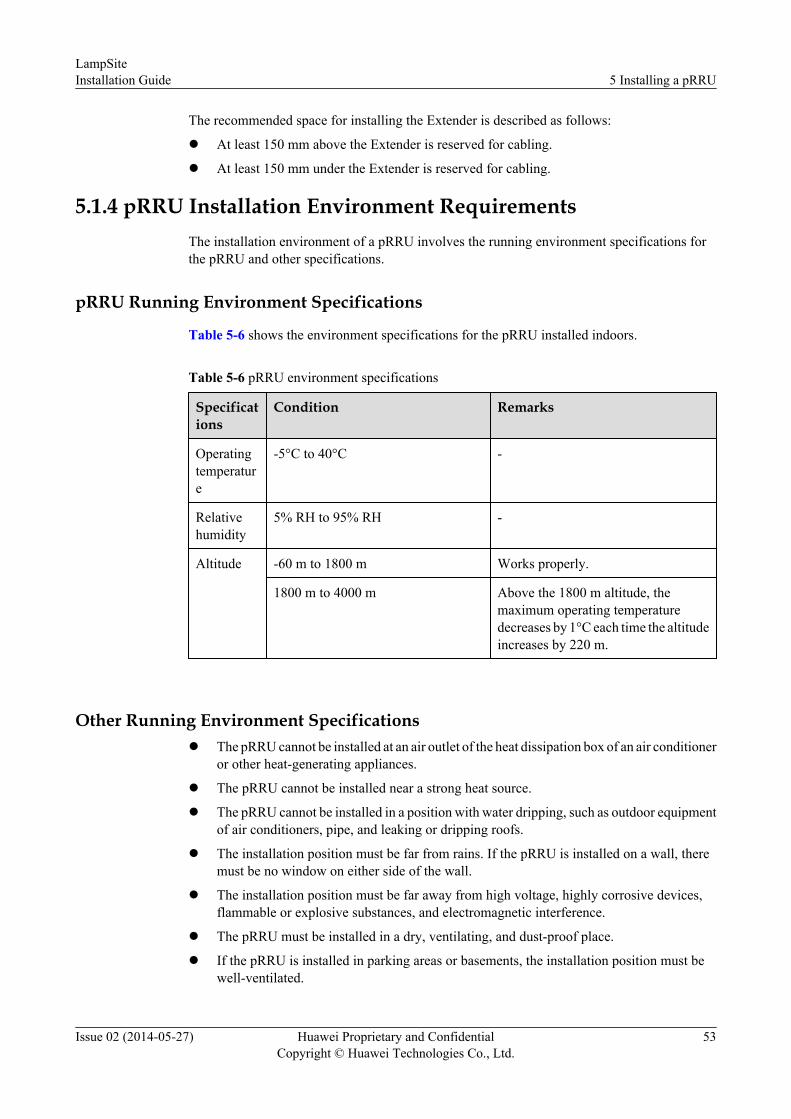
Table 5-6 shows the environment specifications for the pRRU installed indoors.
Table 5-6 pRRU environment specifications
Specifications
Condition Remarks
Operatingtemperature
-5°C to 40°C -
Relativehumidity
5% RH to 95% RH -
Altitude -60 m to 1800 m Works properly.
1800 m to 4000 m Above the 1800 m altitude, themaximum operating temperaturedecreases by 1°C each time the altitudeincreases by 220 m.
Other Running Environment Specificationsl The pRRU cannot be installed at an air outlet of the heat dissipation box of an air conditioner
or other heat-generating appliances.
l The pRRU cannot be installed near a strong heat source.
l The pRRU cannot be installed in a position with water dripping, such as outdoor equipmentof air conditioners, pipe, and leaking or dripping roofs.
l The installation position must be far from rains. If the pRRU is installed on a wall, theremust be no window on either side of the wall.
l The installation position must be far away from high voltage, highly corrosive devices,flammable or explosive substances, and electromagnetic interference.
l The pRRU must be installed in a dry, ventilating, and dust-proof place.
l If the pRRU is installed in parking areas or basements, the installation position must bewell-ventilated.
LampSiteInstallation Guide 5 Installing a pRRU
Issue 02 (2014-05-27) Huawei Proprietary and ConfidentialCopyright © Huawei Technologies Co., Ltd.
53

5.2 Obtaining the MAC Address (Optional)Before installing a pRRU, record the media access control (MAC) address, which will be usedduring pRRU commissioning. This section applies only when a pRRU with three transmissionports is configured with a Wi-Fi daughter board.
ContextThe MAC address indicates the IP address through which a device can be reached.
Procedure
Step 1 Remove the backup WIFI MAC label from the front housing of the pRRU and keep them secure,as shown in Figure 5-4.
NOTE
l Do not remove the WIFI MAC label on the side of the pRRU housing.
l Before removing the backup WIFI MAC label, photograph it.
Figure 5-4 Removing backup WIFI MAC label
Step 2 Save the MAC according to 6.1 MAC Collection Template, and report it to the pRRUcommissioning personnel.
----End
5.3 Installation ProcessThis section describes the pRRU installation process, which involves installing a pRRU, the AC/DC power adapter, and cables, checking the pRRU hardware installation, and powering on thepRRU.
Figure 5-5 shows the pRRU installation process.
LampSiteInstallation Guide 5 Installing a pRRU
Issue 02 (2014-05-27) Huawei Proprietary and ConfidentialCopyright © Huawei Technologies Co., Ltd.
54

Figure 5-5 pRRU installation process
5.4 Installing a pRRUThis section describes the pRRU installation process. A pRRU can be installed on a wall, ceiling,indoor metal pole, or keel. A pRRU can have two transmission ports or three transmission ports,requiring the same installation operations. Unless otherwise specified, this document uses thepRRU with three transmission ports as an example.
LampSiteInstallation Guide 5 Installing a pRRU
Issue 02 (2014-05-27) Huawei Proprietary and ConfidentialCopyright © Huawei Technologies Co., Ltd.
55

NOTE
l The pRRU cannot be grounded. If the pRRU is grounded but the RHUB connected to this pRRU isnot, the pRRU may fail to be powered on.
l A minimum distance of 50 cm must be reserved between the pRRU and the incandescent lamp.
l The installation spacing between the pRRU and the temperature sensor must be greater than 50 cm.
l It is good practice to install the pRRU on materials that can tolerate a temperature higher than 65°Cand have an ignition point higher than 70°C.
5.4.1 pRRU Installation KitsThis section describes the pRRU installation kits.
Figure 5-6 shows the exterior of the pRRU installation kits.
Figure 5-6 pRRU installation kits
(1) V clamp (2) Plate (3) Screw (M6x50)
(4) Plastic expansion sleeve (5) Bolt (M6x80) (6) Flat washer
The following figure shows the specifications of the installation plate.
LampSiteInstallation Guide 5 Installing a pRRU
Issue 02 (2014-05-27) Huawei Proprietary and ConfidentialCopyright © Huawei Technologies Co., Ltd.
56

Figure 5-7 Plate specifications
5.4.2 pRRU Installed on a WallIf the wall indoors has sufficient load bearing capacity and space, the pRRU is recommendedto install on a wall. If the wall cannot bear the capacity, choose an installation mode based onsite requirements.
Context
NOTICEThis section only describes the procedure of installing the pRRU on a wall without any otherauxiliary devices. The installation procedure of other wall-mounted modes is similar to that ofinstalling the pRRU on a wall without auxiliary devices.
Procedure
Step 1 Determine the position for installing the pRRU based on the construction blueprint and the spacerequirements.
NOTE
For pRRU installation space requirements, see 5.1.3 Space Requirements.
Step 2 Place the plate in the installation position against the wall. Then, level the plate and mark thetwo anchor points using a marker, as shown in Figure 5-8.
LampSiteInstallation Guide 5 Installing a pRRU
Issue 02 (2014-05-27) Huawei Proprietary and ConfidentialCopyright © Huawei Technologies Co., Ltd.
57

Figure 5-8 Anchor points of the pRRU installation kits (unit: mm)
(1) Wall (2) Plate (3) Anchor point
CAUTIONTo prevent inhalation or eye contact with dust, take adequate preventive measures when drillingholes.
Step 3 Use a hammer drill with a φ 8 bit to drill holes at the marked anchor points as shown in as shownin Figure 5-9. Use the cleaner to clean the dust inside and around the holes and measure thedistance between them. If they are inaccurately positioned, re-measure and re-drill the holes.Then, use a rubber mallet to push the two plastic expansion sleeve into the holes.
LampSiteInstallation Guide 5 Installing a pRRU
Issue 02 (2014-05-27) Huawei Proprietary and ConfidentialCopyright © Huawei Technologies Co., Ltd.
58

Figure 5-9 Drilling holes and installing expansion bolts
Step 4 Lead the M6x50 screw through the washer, and then through the drilling holes of the plate tothe plastic expansion sleeve, and tighten the screw to a torque of 5 N•m, as shown in Figure5-10.
Figure 5-10 Installing the plate
LampSiteInstallation Guide 5 Installing a pRRU
Issue 02 (2014-05-27) Huawei Proprietary and ConfidentialCopyright © Huawei Technologies Co., Ltd.
59

NOTE
If the screws cannot be tightened using a Phillips screwdriver, use a hex key or an electric screwdriver toassist the installation.
Step 5 Fit the four hooks of the pRRU into the installation kits, as shown in Figure 5-11. If the hooksare properly installed, a slight clack can be heard.
NOTE
It is recommended that you observe the installation from one side of the pRRU when inserting hooks intothe kits.
Figure 5-11 Installing the pRRU on a plate
----End
5.4.3 pRRU Installed on a CeilingThis section describes the procedure of installing a pRRU on the ceiling, such as the concreteceiling, when the ceiling has sufficient load bearing capacity and installation space.
LampSiteInstallation Guide 5 Installing a pRRU
Issue 02 (2014-05-27) Huawei Proprietary and ConfidentialCopyright © Huawei Technologies Co., Ltd.
60
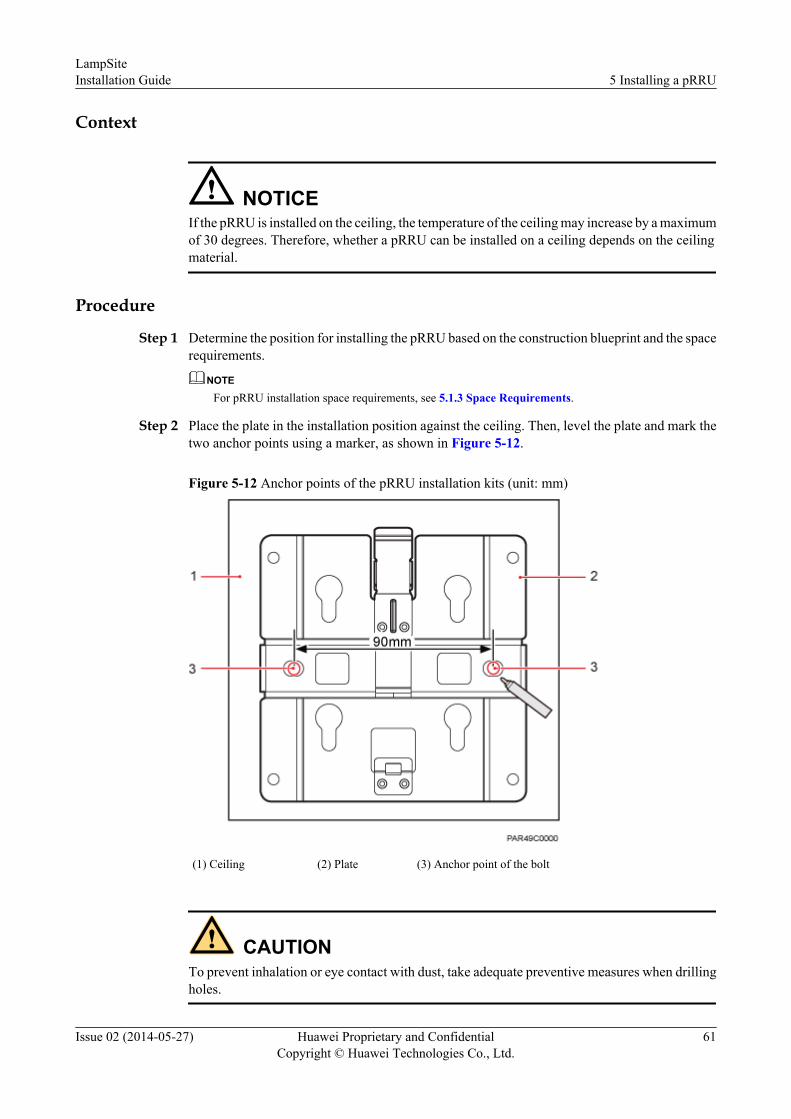
Context
NOTICEIf the pRRU is installed on the ceiling, the temperature of the ceiling may increase by a maximumof 30 degrees. Therefore, whether a pRRU can be installed on a ceiling depends on the ceilingmaterial.
Procedure
Step 1 Determine the position for installing the pRRU based on the construction blueprint and the spacerequirements.
NOTE
For pRRU installation space requirements, see 5.1.3 Space Requirements.
Step 2 Place the plate in the installation position against the ceiling. Then, level the plate and mark thetwo anchor points using a marker, as shown in Figure 5-12.
Figure 5-12 Anchor points of the pRRU installation kits (unit: mm)
(1) Ceiling (2) Plate (3) Anchor point of the bolt
CAUTIONTo prevent inhalation or eye contact with dust, take adequate preventive measures when drillingholes.
LampSiteInstallation Guide 5 Installing a pRRU
Issue 02 (2014-05-27) Huawei Proprietary and ConfidentialCopyright © Huawei Technologies Co., Ltd.
61

Step 3 Use a hammer drill with a φ 8 bit to drill holes at the marked anchor points as shown in as shownin Figure 5-13. Use the cleaner to clean the dust inside and around the holes and measure thedistance between them. If they are inaccurately positioned, re-measure and re-drill the holes.Then, use a rubber mallet to push the two plastic expansion sleeve into the holes.
Figure 5-13 Drilling holes and installing expansion bolts
Step 4 Lead the M6x50 screw through the washer, and then through the drilling holes of the plate tothe plastic expansion sleeve, and use a torque screwdriver to tighten the screw with a torque of5 N•m, as shown in Figure 5-14.
Figure 5-14 Installing the plate
NOTE
If the screws cannot be tightened using a Phillips screwdriver, use a hex key or an electric screwdriver toassist the installation.
LampSiteInstallation Guide 5 Installing a pRRU
Issue 02 (2014-05-27) Huawei Proprietary and ConfidentialCopyright © Huawei Technologies Co., Ltd.
62

Step 5 Fit the four hooks of the pRRU into the installation kits, as shown in Figure 5-15. If the hooksare properly installed, a slight clack can be heard.
NOTE
It is recommended that you observe the installation from one side of the pRRU when inserting hooks intothe kits.
Figure 5-15 Installing a pRRU
----End
5.4.4 pRRU Installed on a PoleA pRRU can be installed on a metal pole indoors.
Procedure
Step 1 Determine the position for installing the pRRU based on the construction blueprint and the spacerequirements.
NOTE
For pRRU installation space requirements, see 5.1.3 Space Requirements.
Step 2 If the diameter of the pole ranges from 30 mm to 70 mm, use the delivered V clamp, installationplate, and bolts to install the pRRU on the pole. Lead the M6x80 bolt through the plate, andtighten the bolt to a torque of 5 N•m, as shown in Figure 5-16.
LampSiteInstallation Guide 5 Installing a pRRU
Issue 02 (2014-05-27) Huawei Proprietary and ConfidentialCopyright © Huawei Technologies Co., Ltd.
63
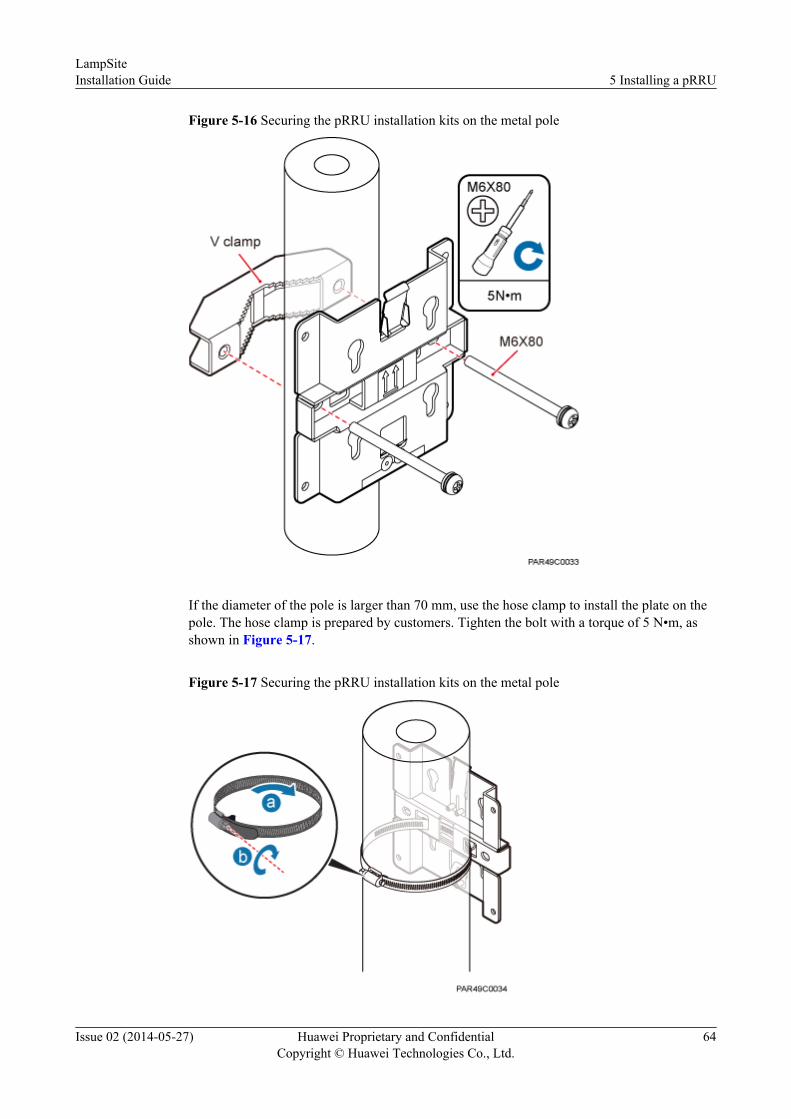
Figure 5-16 Securing the pRRU installation kits on the metal pole
If the diameter of the pole is larger than 70 mm, use the hose clamp to install the plate on thepole. The hose clamp is prepared by customers. Tighten the bolt with a torque of 5 N•m, asshown in Figure 5-17.
Figure 5-17 Securing the pRRU installation kits on the metal pole
LampSiteInstallation Guide 5 Installing a pRRU
Issue 02 (2014-05-27) Huawei Proprietary and ConfidentialCopyright © Huawei Technologies Co., Ltd.
64

Step 3 Fit the four hooks of the pRRU into the installation kits, as shown in Figure 5-18. If the hooksare properly installed, a slight clack can be heard.
NOTE
It is recommended that you observe the installation from one side of the pRRU when inserting hooks intothe kits.
Figure 5-18 Installing a pRRU
----End
5.4.5 pRRU Installed on a PlateIf the plate on the ceiling has sufficient load bearing capacity and space installation, the pRRUcan be installed on the plate of the ceiling indoors.
Procedure
Step 1 Determine the position for installing the pRRU based on the construction blueprint and the spacerequirements.
NOTE
For pRRU installation space requirements, see 5.1.3 Space Requirements.
Step 2 Place the plate in the installation position against the wall. Then, level the plate and mark thetwo anchor points using a marker, as shown in Figure 5-19.
LampSiteInstallation Guide 5 Installing a pRRU
Issue 02 (2014-05-27) Huawei Proprietary and ConfidentialCopyright © Huawei Technologies Co., Ltd.
65

Figure 5-19 Anchor points of the pRRU installation kits (unit: mm)
(1) Panel (2) Plate (3) Anchor point
CAUTIONTo prevent inhalation or eye contact with dust, take adequate preventive measures when drillingholes.
Step 3 Use a hammer drill with bit 8 to drill holes at the anchor points.
Step 4 Lead the bolt M6x80 through the panel and daughter board, and tighten the torque screwdriverto a torque of 5 N•m, as shown in Figure 5-20.
LampSiteInstallation Guide 5 Installing a pRRU
Issue 02 (2014-05-27) Huawei Proprietary and ConfidentialCopyright © Huawei Technologies Co., Ltd.
66

Figure 5-20 Installing the pRRU installation kits
Step 5 Fit the four hooks of the pRRU into the installation kits, as shown in Figure 5-21. If the hooksare properly installed, a slight clack can be heard.
NOTE
It is recommended that you observe the installation from one side of the pRRU when inserting hooks intothe kits.
LampSiteInstallation Guide 5 Installing a pRRU
Issue 02 (2014-05-27) Huawei Proprietary and ConfidentialCopyright © Huawei Technologies Co., Ltd.
67

Figure 5-21 Installing a pRRU
----End
5.4.6 pRRU Installed on a KeelIf the ceiling cover cannot bear the pRRU, the pRRU can be installed on the keel of a ceiling.
Context
Before installing the pRRU on a keel, ensure that the keel is strong enough to bear the pRRU.
l The installation kits of the pRRU can be installed on the keel of the following specifications:GBT 11981-2008, JIS A6517-2002, and ASTM C635 C635M-2007. The installation modemust depends on onsite requirements because there are various keels.
l This section describes the procedure of installing a pRRU on the keel of JIS standard usedin Japan. The procedure of installing a pRRU on other keels is the same as that of installinga pRRU on the keel of JIS standard.
Procedure
Step 1 Determine the position for installing the pRRU based on the construction blueprint and the spacerequirements.
NOTE
For pRRU installation space requirements, see 5.1.3 Space Requirements.
Step 2 Lead the V clamp on across the keel, and mark the projective position on the cover with a marker,as shown in Figure 5-22.
LampSiteInstallation Guide 5 Installing a pRRU
Issue 02 (2014-05-27) Huawei Proprietary and ConfidentialCopyright © Huawei Technologies Co., Ltd.
68

Figure 5-22 Anchor points on a plate (unit: mm)
CAUTIONTo prevent inhalation or eye contact with dust, take adequate preventive measures when drillingholes.
Step 3 Use a hammer drill to drill holes at the anchor points. You are advised to use the hammer drillФ12.
Step 4 Lead the bolt M6x80 through the installation plate and ceiling cover, and then socket to tightenthe bolt to a torque of 5 N•m, as shown in Figure 5-23.
LampSiteInstallation Guide 5 Installing a pRRU
Issue 02 (2014-05-27) Huawei Proprietary and ConfidentialCopyright © Huawei Technologies Co., Ltd.
69

Figure 5-23 Installing the pRRU installation kits
Step 5 Fit the four hooks of the pRRU into the installation kits, as shown in Figure 5-24. If the hooksare properly installed, a slight clack can be heard.
NOTE
It is recommended that you observe the installation from one side of the pRRU when inserting hooks intothe kits.
LampSiteInstallation Guide 5 Installing a pRRU
Issue 02 (2014-05-27) Huawei Proprietary and ConfidentialCopyright © Huawei Technologies Co., Ltd.
70

Figure 5-24 Installing a pRRU
----End
5.5 Installing the AC/DC Power Adapter (Optional)The pRRU can obtain power supply using the AC/DC power adapter, which is used as required.An AC/DC power adapter is small and can be installed on a wall or pole. When it is installed, asupport for it is required.
Contextl An AC/DC power adapter is small and can be installed on a wall or pole. When it is installed,
a support for it is required.l The distance between the AC/DC power adapter and the pRRU must be within 1.5 m.
Procedurel Wall-mounted
1. Use a marker to mark the two anchor points of the support for the AC/DC adapterwhich is level to the wall. The interval of the two anchor points is 50 mm, as shownin Figure 5-25.
LampSiteInstallation Guide 5 Installing a pRRU
Issue 02 (2014-05-27) Huawei Proprietary and ConfidentialCopyright © Huawei Technologies Co., Ltd.
71

Figure 5-25 Anchor points of the support for the AC/DC power adapter (unit: mm)
2. Use a hammer drill Ф6 to drill holes at anchor points, as shown in Figure 5-26 Thediameter of the hole is 6 mm, the depth is 25mm to 30 mm, and the interval of the twoholes is 50 mm.
Figure 5-26 Drilling holes and installing expansion bolts
3. Use two tapping screws to secure the power adapter support to the wall, as shown inFigure 5-27.
LampSiteInstallation Guide 5 Installing a pRRU
Issue 02 (2014-05-27) Huawei Proprietary and ConfidentialCopyright © Huawei Technologies Co., Ltd.
72

Figure 5-27 Tightening the power adapter support
4. Place the AC/DC power adapter on the support by referring to Figure 5-28.
LampSiteInstallation Guide 5 Installing a pRRU
Issue 02 (2014-05-27) Huawei Proprietary and ConfidentialCopyright © Huawei Technologies Co., Ltd.
73

Figure 5-28 Installing the AC/DC power adapter
l On a pole1. Route the cable ties through the notches on the support and secure the fixing hoops to
a pole, as shown in Figure 5-29.
LampSiteInstallation Guide 5 Installing a pRRU
Issue 02 (2014-05-27) Huawei Proprietary and ConfidentialCopyright © Huawei Technologies Co., Ltd.
74

Figure 5-29 Wrap binding straps
2. Place the AC/DC power adapter on the support by referring to Figure 5-30.
Figure 5-30 Wrap binding straps
----End
5.6 Installing the Extender (Optional)This section describes the Extender installation process.
Context
When an RHUB and a pRRU need extended install, use extender. With the Extender, the distanceof the pRRU and RHUB can be extended by the Extender up to a total distance of 200 m.
LampSiteInstallation Guide 5 Installing a pRRU
Issue 02 (2014-05-27) Huawei Proprietary and ConfidentialCopyright © Huawei Technologies Co., Ltd.
75

Procedure
Step 1 Use a marker to mark the two anchor points according to inter-hole spacing, as shown in Figure5-31.
Figure 5-31 Marking anchor points
Step 2 Drill holes at the anchor points, and install expansion bolt assemblies, as shown in Figure5-32. The diameter of the hole is 6 mm, and the depth is 25 mm to 30 mm.
Figure 5-32 Drilling holes and installing expansion bolts
Step 3 Place the Extender in the corresponding position and use an M4 Phillips screwdriver to tightenthe screws to 1.4 N•m, as shown in Figure 5-33.
LampSiteInstallation Guide 5 Installing a pRRU
Issue 02 (2014-05-27) Huawei Proprietary and ConfidentialCopyright © Huawei Technologies Co., Ltd.
76

Figure 5-33 Installing Extender
----End
5.7 Installing pRRU CablesThis section describes the procedure of installing the pRRU cables.
5.7.1 Cabling RequirementsCables must be routed according to the specified cabling requirements to prevent signalinterference.
NOTE
If certain cables listed below are not required, skip the requirements for routing these cables.
General Requirements for Cable Layout
Bending radius
l The bending radius of a 1/4'' jumper, a 1/2'' softer jumper, and a 1/2'' common jumper mustbe longer than 35 mm, 50 mm, and 127 mm, respectively.
l The bending radius of a power cable is at least three times the diameter of the cable.
l The bending radius of a signal cable must be at least five times of the diameter of the cable.
Cable binding
l Cables of the same type are bound together.
LampSiteInstallation Guide 5 Installing a pRRU
Issue 02 (2014-05-27) Huawei Proprietary and ConfidentialCopyright © Huawei Technologies Co., Ltd.
77

l Different types of cables must be separately routed with a minimum spacing of 30 mm andcannot be entangled.
l The cables are bound tightly and neatly and the sheaths of the cables is intact.
l The cable ties face the same direction and all cable ties bound at similar positions must bein a straight line.
l The extra length of each indoor cable tie must be cut off. A slack of 5 mm is reserved foreach outdoor cable tie before the extra length is cut off. All cut surfaces are without sharpedges.
l Labels or nameplates are attached to both ends, joints, or turns of cables after they areinstalled.
Safetyl Cables are placed away from sharp objects or wall burrs. If these positions are inevitable,
protection pipes are required for the cables.
l Cables are routed away from heat sources, or heat-insulation materials are added betweencables and heat sources.
l A clearance is reserved at turns of a cable or the position close to a device, facilitating cableand device maintenance. The recommended clearance is about 0.1 m.
5.7.2 List of pRRU CablesThis section describes pRRU cable connections.
Table 5-7 lists pRRU cables.
Table 5-7 List of pRRU cables
Cable One End The Other End
Connector Connectedto ...
Connector Connected to ...
EthernetCable
RJ45 connector RHUB/CPRI_E0~CPRI_E7 port
RJ45 connector pRRU/CPRI_E0~CPRI_E1 port
RJ45 connector AC orTransmissionport
RJ45 connector pRRU/GE port
pRRU RFJumper
SMA straightmale connector
Externalantenna TX/RX RF port onthe pRRU
Based on the portmodel of theantenna system.
Antenna system
AdapterPower Cable
C13 femaleconnector
C14 maleconnector onthe AC/DCadapter
Based on thecountry and areawhere theconnector isused.
AC power socket
LampSiteInstallation Guide 5 Installing a pRRU
Issue 02 (2014-05-27) Huawei Proprietary and ConfidentialCopyright © Huawei Technologies Co., Ltd.
78
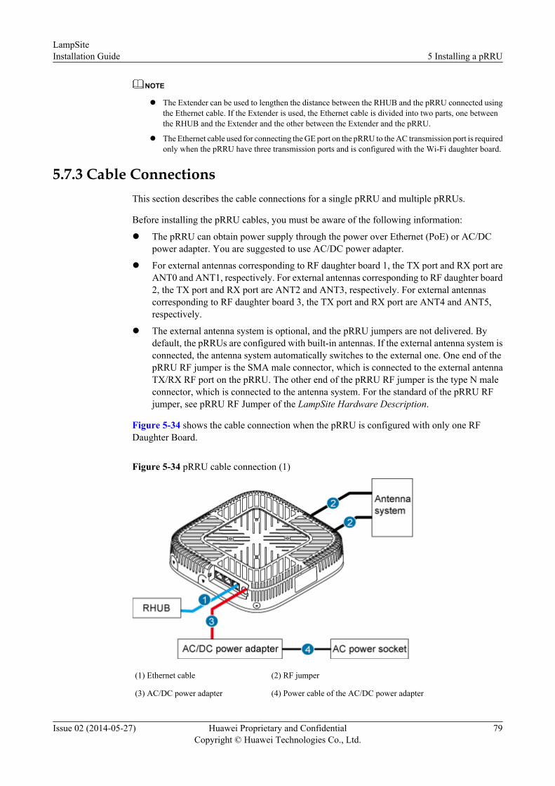
NOTE
l The Extender can be used to lengthen the distance between the RHUB and the pRRU connected usingthe Ethernet cable. If the Extender is used, the Ethernet cable is divided into two parts, one betweenthe RHUB and the Extender and the other between the Extender and the pRRU.
l The Ethernet cable used for connecting the GE port on the pRRU to the AC transmission port is requiredonly when the pRRU have three transmission ports and is configured with the Wi-Fi daughter board.
5.7.3 Cable ConnectionsThis section describes the cable connections for a single pRRU and multiple pRRUs.
Before installing the pRRU cables, you must be aware of the following information:
l The pRRU can obtain power supply through the power over Ethernet (PoE) or AC/DCpower adapter. You are suggested to use AC/DC power adapter.
l For external antennas corresponding to RF daughter board 1, the TX port and RX port areANT0 and ANT1, respectively. For external antennas corresponding to RF daughter board2, the TX port and RX port are ANT2 and ANT3, respectively. For external antennascorresponding to RF daughter board 3, the TX port and RX port are ANT4 and ANT5,respectively.
l The external antenna system is optional, and the pRRU jumpers are not delivered. Bydefault, the pRRUs are configured with built-in antennas. If the external antenna system isconnected, the antenna system automatically switches to the external one. One end of thepRRU RF jumper is the SMA male connector, which is connected to the external antennaTX/RX RF port on the pRRU. The other end of the pRRU RF jumper is the type N maleconnector, which is connected to the antenna system. For the standard of the pRRU RFjumper, see pRRU RF Jumper of the LampSite Hardware Description.
Figure 5-34 shows the cable connection when the pRRU is configured with only one RFDaughter Board.
Figure 5-34 pRRU cable connection (1)
(1) Ethernet cable (2) RF jumper
(3) AC/DC power adapter (4) Power cable of the AC/DC power adapter
LampSiteInstallation Guide 5 Installing a pRRU
Issue 02 (2014-05-27) Huawei Proprietary and ConfidentialCopyright © Huawei Technologies Co., Ltd.
79

NOTE
l The Extender can be used to lengthen the distance between the RHUB and the pRRU connected usingthe Ethernet cable. If the Extender is used, the Ethernet cable is divided into two parts, one betweenthe RHUB and the Extender and the other between the Extender and the pRRU.
l When two Ethernet cables are used to transmit CPRI signals, connect one end of the cables to theCPRI_E0 and CPRI_E1 ports on the pRRU panel and the other end to any two ports of CPRI_E0 toCPRI_E7 on the RHUB panel. This document describes signal transmission using one Ethernet cableas an example.
Figure 5-35 shows the cable connection when the pRRU is configured with two RF DaughterBoards.
Figure 5-35 pRRU cable connection (2)
(1) Ethernet cable (2) RF jumper
(3) AC/DC power adapter (4) Power cable of the AC/DC power adapter
NOTE
l The Extender can be used to lengthen the distance between the RHUB and the pRRU connected usingthe Ethernet cable. If the Extender is used, the Ethernet cable is divided into two parts, one betweenthe RHUB and the Extender and the other between the Extender and the pRRU.
l When two Ethernet cables are used to transmit CPRI signals, connect one end of the cables to theCPRI_E0 and CPRI_E1 ports on the pRRU panel and the other end to any two ports of CPRI_E0 toCPRI_E7 on the RHUB panel. This document describes signal transmission using one Ethernet cableas an example.
5.7.4 Cable Connections (LTE TDD)This section describes the cable connections for a single pRRU and multiple pRRUs.
Before installing the pRRU cables, you must be aware of the following information:l The pRRU can obtain power supply through the power over Ethernet (PoE) or AC/DC
power adapter. You are suggested to use AC/DC power adapter.l For external antennas corresponding to RF daughter board 1, the TX port and RX port are
ANT0 and ANT1, respectively. For external antennas corresponding to RF daughter board
LampSiteInstallation Guide 5 Installing a pRRU
Issue 02 (2014-05-27) Huawei Proprietary and ConfidentialCopyright © Huawei Technologies Co., Ltd.
80

2, the TX port and RX port are ANT2 and ANT3, respectively. For external antennascorresponding to RF daughter board 3, the TX port and RX port are ANT4 and ANT5,respectively.
l The external antenna system is optional, and the pRRU jumpers are not delivered. Bydefault, the pRRUs are configured with built-in antennas. If the external antenna system isconnected, the antenna system automatically switches to the external one. One end of thepRRU RF jumper is the SMA male connector, which is connected to the external antennaTX/RX RF port on the pRRU. The other end of the pRRU RF jumper is the type N maleconnector, which is connected to the antenna system. For the standard of the pRRU RFjumper, please see pRRU RF Jumper of the LampSite Hardware Description.
Figure 5-36 shows the cable connection when the pRRU is configured with only one RFDaughter Board.
Figure 5-36 pRRU cable connection (1)
(1) Ethernet cable (2) RF jumper
(3) AC/DC power adapter (4) Power cable of the AC/DC power adapter
NOTE
The Extender can be used to lengthen the distance between the RHUB and the pRRU connected using theEthernet cable. If the Extender is used, the Ethernet cable is divided into two parts, one between the RHUBand the Extender and the other between the Extender and the pRRU.
Figure 5-37 shows the cable connection when the pRRU is configured with two RF DaughterBoards.
LampSiteInstallation Guide 5 Installing a pRRU
Issue 02 (2014-05-27) Huawei Proprietary and ConfidentialCopyright © Huawei Technologies Co., Ltd.
81

Figure 5-37 pRRU cable connection (2)
(1) Ethernet cable (2) RF jumper
(3) AC/DC power adapter (4) Power cable of the AC/DC power adapter
NOTE
The Extender can be used to lengthen the distance between the RHUB and the pRRU connected using theEthernet cable. If the Extender is used, the Ethernet cable is divided into two parts, one between the RHUBand the Extender and the other between the Extender and the pRRU.
5.7.5 pRRU cable installation processThis section describes the process of installing pRRU cables.
Figure 5-38 shows the process of installing pRRU cables.
Figure 5-38 pRRU cable installation process
LampSiteInstallation Guide 5 Installing a pRRU
Issue 02 (2014-05-27) Huawei Proprietary and ConfidentialCopyright © Huawei Technologies Co., Ltd.
82

5.7.6 Installing an Ethernet CableThis section describes how to install an Ethernet cable.
Prerequisitesl Ethernet cables are not delivered, and they must be prepared onsite. You need to use a
network cable tester to test the Ethernet cable connection.
l Cables of Category 5e (enhanced) or higher specification is used for connecting the RHUBand pRRU. With the internal PoE module providing power, the distance of the pRRU andRHUB can be extended by the Extender up to a total distance of 100 m. With the Extender,the distance of the pRRU and RHUB can be extended by the Extender up to a total distanceof 200 m.
Context
The Ethernet cable has the following functions:
l Provides power supply for the pRRU when the cable connects the CPRI_E0 port on thepRRU to the RHUB.
l Transmits CPRI signals between an RHUB and a pRRU.
l Provides Wi-Fi services for the pRRU when the cable connects the GE port on the pRRUwith three transmission ports to the AC.
NOTE
l A pRRU can have two transmission ports or three transmission ports, requiring the same installationoperations. This section uses the pRRU with three transmission ports as an example.
l Using the CPRI_E1 port on the pRRU has the same Ethernet cable connection to the RHUB as usingthe CPRI_E0 port. The following section describes the connection using the CPRI_E0 port.
Procedure
Step 1 Install an Ethernet cable between an RHUB and a pRRU.
1. Remove the dustproof cap of the CPRI_E0 port on the pRRU.
2. Connect the RJ45 connector at one end of the Ethernet cable to the CPRI_E0 port on thepRRU panel.
3. Optional: Connect the RJ45 connector at the other end of the Ethernet cable to the outputport of the Extender. Then, connect the RJ45 connector at one end of another Ethernet cableto the input port of the Extender.
4. Connect the RJ45 connector at the other end of the Ethernet cable to any port ranging fromCPRI_E0 to CPRI_E7 on the RHUB panel based on the engineering design, as shown inFigure 5-39.
Step 2 Optional: Install the Ethernet cable between the pRRU and the AC. This operation is requiredwhen the pRRU with three transmission ports is configured with a Wi-Fi daughter board.
1. Remove the dustproof cap of the GE port on the pRRU.
2. Connect the RJ45 connector at one end of the Ethernet cable to the GE port on the pRRUpanel.
LampSiteInstallation Guide 5 Installing a pRRU
Issue 02 (2014-05-27) Huawei Proprietary and ConfidentialCopyright © Huawei Technologies Co., Ltd.
83

3. Connect the RJ45 connector at the other end of the Ethernet cable to the transmission portof the AC based on the engineering design, as shown in Figure 5-39.
Figure 5-39 Installing an Ethernet cable
(1) Ethernet cable (2) GE port on the pRRU (3) CPRI_E0 port on the pRRU
NOTE
The Extender can be used to lengthen the distance between the RHUB and the pRRU connected using theEthernet cable. If the Extender is used, the Ethernet cable is divided into two parts, one between the RHUBand the Extender and the other between the Extender and the pRRU.
----End
5.7.7 Installing pRRU Jumpers (Optional)pRRU jumpers transmit radio frequency signals. One end of the jumper is the SMA straight maleconnector, and the other end is the type N connector.
Contextl If the RF jumper is provided by the customer, the jumper must not be lower than the RG316
specifications. In addition, the jumpers can be used after they are checked by Huaweiengineers.
l pRRUs can be connected to external whip antennas or external remote antennas (throughpRRU RF jumpers). Whip antennas are delivered optionally. RF jumpers are not delivered.
Procedure
Step 1 Expose the SMA female connector by removing the pRRU antenna housing, as shown in Figure5-40.
LampSiteInstallation Guide 5 Installing a pRRU
Issue 02 (2014-05-27) Huawei Proprietary and ConfidentialCopyright © Huawei Technologies Co., Ltd.
84

Figure 5-40 Removing the pRRU antenna housing
Step 2 Use a torque wrench with a torque of 0.6 N•m to connect the SMA straight male connector ona jumper to the ANT port on the pRRU panel.
NOTICETighten it with hands, and then use a torque wrench to tighten it with a rotational speed of lessthan or equal to 2.4 rpm to tighten it.
Step 3 Connect the type N female connector of the jumper to the type N male connector of the RF feederconnected to the built-in antenna.
NOTICETighten the feeder close to the type N connector to ensure that the jumper is not tightened. Inthis way, the connectors on both ends of a jumper are not affected by the external force.
LampSiteInstallation Guide 5 Installing a pRRU
Issue 02 (2014-05-27) Huawei Proprietary and ConfidentialCopyright © Huawei Technologies Co., Ltd.
85

Figure 5-41 Installing jumpers between the pRRU and external antennas
----End
5.7.8 Installing adapter power cablesThe pRRU can be powered by the AC/DC power adapter.
Prerequisitesl The pRRU use the AC/DC power adapter to obtain power supply, and the AC/DC power
adapter is installed.
Contextl One end of the adapter power cable is the C13 female connector, which is connected to the
C14 male connector on the adapter, and the other end of the adapter power cable isconnected to the AC power socket.
Procedure
Step 1 The X1 end is connected to the PWR port on the pRRU, as shown in Figure 5-42.
Step 2 The X2 end (the C13 female connector on the AC/DC power adapter cable) is connected to theAC power input port, as shown in Figure 5-42.
Step 3 The X3 end is connected to the external power supply port of the AC adapter, as shown in Figure5-42.
LampSiteInstallation Guide 5 Installing a pRRU
Issue 02 (2014-05-27) Huawei Proprietary and ConfidentialCopyright © Huawei Technologies Co., Ltd.
86

Figure 5-42 Installing adapter power cables
Step 4 Route cables by referring to 4.4.1 Requirements for Cable Layout.
----End
5.8 Checking the pRRU Hardware InstallationpRRU hardware installation checking includes hardware and cable installation checking.
Table 5-8 lists the hardware installation checking items.
Table 5-8 Hardware installation checking list
No. Item
1 Ensure that the pRRU is not grouned.
2 The position for each device conforms to the engineering design and meets thespace requirement.
3 Ensure that the pRRU is properly installed.
4 The surface of the pRRU is neat and clean. The external paint is intact. The labels,tags, and nameplates are correct, legible, and complete.
Table 5-9 lists the check items of the signal cable connection.
Table 5-9 Checklist for the signal cable connection
No. Item
1 The connectors of the signal cables must securely connected.
2 The connectors of the signal cables are intact.
3 The signal cables are intact.
LampSiteInstallation Guide 5 Installing a pRRU
Issue 02 (2014-05-27) Huawei Proprietary and ConfidentialCopyright © Huawei Technologies Co., Ltd.
87

No. Item
4 The cable ties are evenly spaced. The signal cables are bound neatly with cableties to proper tightness, and arranged at even intervals in the same direction.
5 The extra length of the cable ties is cut and removed. The cut surfaces of the indoorcables are smooth and have no sharp edges.
6 The cable layout facilitates maintenance and expansion.
7 Correct and clear labels are attached to both ends of the signal cables.
Table 5-10 lists the checking items for other cable connections.
Table 5-10 Checklist for other cable connections
No. Item
1 The connectors of the other cables must securely connected.
2 Labels on the cables are legible and bound based on the engineering requirements.The cables must be bound tightly and neatly. The sheaths of the cables must notbe damaged.
3 Positions for routing the cables must meet requirements of the engineering design.
5.9 Powering on the pRRUThis section describes the power-on check on the pRRU after the pRRU hardware is installedand checked.
Procedure
Step 1 Optional: Measure the voltage of the pRRU. This operation is required when AC/DC poweradapter is used.
If... Then...
The voltage of the AC power adapterranges from 100 V AC to 240 V AC (AC/DC power adapter is used)
Go to Step 2. Otherwise, check for the cause untilthe voltage meets the requirement, and go to Step2.
Step 2 Power on the pRRU. Wait 3 to 5 minutes, check the status of the RUN indicator on the pRRU.
LampSiteInstallation Guide 5 Installing a pRRU
Issue 02 (2014-05-27) Huawei Proprietary and ConfidentialCopyright © Huawei Technologies Co., Ltd.
88

If the RUN Indicator... Because... Then...
Steady on There is power input, but theboard is faulty.
Power off the power supply,rectify the fault, and power onthe pRRU.
Steady off There is no power input, or analarm is reported on the board.
Power off the power supplyand check the power input. Ifno fault is found after thepRRU is powered off, clear thefault on the board, and poweron the pRRU.
On for 1s and off for 1s The device works properly. End this operation.
On for 0.125s and off for0.125s
The software of the board isloading.
Wait five minutes for thesoftware to be successfullyloaded. If the software isloading five minutes later, shutoff the power supply. Checkwhether the data configurationfile is correct. After the fault isrectify, power on the pRRUagain.
----End
LampSiteInstallation Guide 5 Installing a pRRU
Issue 02 (2014-05-27) Huawei Proprietary and ConfidentialCopyright © Huawei Technologies Co., Ltd.
89

6 Appendix
About This Chapter
This chapter describes reference information during installation and the procedures for installingRF daughter boards on a pRRU in capacity expansion scenarios.
6.1 MAC Collection TemplateThis section describes the MAC collection template for a pRRU with three transmission ports.
6.2 Installing RF Daughter Boards on a pRRU (in Capacity Expansion Scenarios)This section describes the procedures for installing RF daughter boards on a pRRU. A pRRUcan have two transmission ports or three transmission ports, requiring the same installationoperations. This section uses the pRRU with three transmission ports as an example.
LampSiteInstallation Guide 6 Appendix
Issue 02 (2014-05-27) Huawei Proprietary and ConfidentialCopyright © Huawei Technologies Co., Ltd.
90

6.1 MAC Collection TemplateThis section describes the MAC collection template for a pRRU with three transmission ports.
The MAC collection template is used to record the installation position, MAC address of thesite at the initial installation stage to facilitate subsequent commissioning and maintenance.Table 6-1 shows the MAC collection template.
Table 6-1 MAC collection template
No. SiteNumber
Site Name WIFI MAC Location Information
Sample
01 pRRU3901 xx floor, xx building, xxmansion
Note: The MAC collection template is essential to the engineering stage and subsequentmaintenance, especially when multiple devices are installed at a short distance. This isbecause the template defines the radio network to access. Maintain this template withcaution.
6.2 Installing RF Daughter Boards on a pRRU (in CapacityExpansion Scenarios)
This section describes the procedures for installing RF daughter boards on a pRRU. A pRRUcan have two transmission ports or three transmission ports, requiring the same installationoperations. This section uses the pRRU with three transmission ports as an example.
ContextThe preferred slot for an RF daughter board depends on the mode of the RF daughter board.
Figure 6-1 shows the slot for installing the RF daughter boards.
LampSiteInstallation Guide 6 Appendix
Issue 02 (2014-05-27) Huawei Proprietary and ConfidentialCopyright © Huawei Technologies Co., Ltd.
91

Figure 6-1 Slot for installing the RF daughter boards
NOTE
l Unless otherwise specified, LTE mode in this document refers to LTE TDD and LTE FDD.
l This section describes how to install an RF daughter board in slot S2 as an example.
Procedure
Step 1 Instruct the network operator to block the pRRU.l On the UMTS side, log in to the LMT and run the BLK BRD command to block the RF
daughter board.l On the LTE side, log in to the LMT and run the BLK BRD command to block the RF daughter
board.
CAUTIONA pRRU that has just been powered off has afterheat. Take scald-proof measures when removingthe modules.
Step 2 Power off the pRRU.Powering off the pRRU interrupts all the services carried on the pRRU.
Step 3 Wear ESD gloves.
NOTICETake proper ESD protection measures. For example, wear ESD gloves to prevent electrostaticdamage to the boards, modules, or electronic components.
Step 4 Use an M4 Phillips screwdriver to loosen the Phillips screw on the pRRU housing. Wrench andremove the housing from the installation position of the Phillips screw hole, as shown in Figure6-2.
LampSiteInstallation Guide 6 Appendix
Issue 02 (2014-05-27) Huawei Proprietary and ConfidentialCopyright © Huawei Technologies Co., Ltd.
92

Figure 6-2 Removing the pRRU housing
NOTE
l Either Phillips screws or protection screws can be used for installing the pRRU housing and the RFdaughter board, requiring the same installation operations. This section uses Phillips screws as anexample to describe the installation operations.
l Keep the Phillips screw secure for future use.
Step 5 Install an RF daughter board in slot S2.
1. Remove the protective cover from the RF daughter board connector of slot S2.
2. Level the handles of an RF daughter board of the required mode, and insert the handlesseparately in the two dowels of slot S2, and use the M4 Phillips screwdriver to tighten thetwo Phillips screws on the RF daughter board with a torque of 1.4 N•m, as shown in Figure6-3.
Figure 6-3 Installing the RF daughter board in slot S2
LampSiteInstallation Guide 6 Appendix
Issue 02 (2014-05-27) Huawei Proprietary and ConfidentialCopyright © Huawei Technologies Co., Ltd.
93

Step 6 Remove the SN label and mode label on the surface of the RF daughter board, as shown inFigure 6-4.
Figure 6-4 Removing the SN label and mode label
Step 7 Attach the removed SN label to the corresponding position for S2 label on the nameplate sideof the pRRU housing and the mode label to a position (for the label of slot S2 on the side of thepRRU housing) between antenna ports ANT2 and ANT3, as shown in Figure 6-5.
Figure 6-5 Attaching the SN label and mode label
Step 8 Close the pRRU housing and tamp each side of the housing until a click is heard. Ensure thatthe groove gaps between the front and back housings are evenly distributed. Use the M4 Phillipsscrewdriver to tighten the Phillips screw on the housing with a torque of 1.4 N•m, as shown inFigure 6-6.
LampSiteInstallation Guide 6 Appendix
Issue 02 (2014-05-27) Huawei Proprietary and ConfidentialCopyright © Huawei Technologies Co., Ltd.
94

Figure 6-6 Installing the pRRU housing
NOTE
The Phillips screw is the one removed and kept in Step 4.
Step 9 Power on the pRRU.
Step 10 Instruct the network operator to unblock the pRRU.l On the UMTS side, log in to the NodeB LMT and run the UBL BRD command to unblock
the RF daughter board of the pRRU.l On the LTE side, log in to the eNodeB LMT and run the UBL BRD command to unblock
the RF daughter board of the pRRU.
Step 11 Take off the ESD gloves and pack up all the tools.
----End
LampSiteInstallation Guide 6 Appendix
Issue 02 (2014-05-27) Huawei Proprietary and ConfidentialCopyright © Huawei Technologies Co., Ltd.
95