installation - bahnhof ab
TRANSCRIPT

Dear customer, Thank you for your purchase of the SARA VCF eurorack module. The Sara VCF is a fully voltage controlled state variable filter with dual “opposing” self oscillating cores. The tone capabilities can range from delicate to outrageous and all stops in between. Everything from classic vintage twin filter setups, oscillator into filter (quasilpg), self oscillation and formant style soundscapes. The Sara VCF does well both in classic duties and experimental sounds (just try self patching the state control from one of the core outs) With CV over every control the modulation possibilities open the palette of sound even further. Read on to get the best out of your new module. Your new module comes with 12 months free technical support for the original purchaser, just drop an email to [email protected] if you have any questions or problems. Again thank you for your purchase, it’s much appreciated. And don’t forget to keep an eye on http://www.dinsync.info for the forthcoming modules. Paul

Who reads manuals anyway? I know right? but please take a quick read of the following.
Installation
The SARA VCF has reverse power protection, so plugging the power cable in backwards should result in no damage to the module itself. However plugging things in backwards is never a good idea and could potentially damage other parts of your system. The protection is there in case of plugging the power cable in backwards by accident, please still take care to check the orientation of the cable when connecting it for the first time.
figure 1 the correct and wrong way to connect power
Before installing please power off your modular case. Connect one end of the cable to the module as shown in figure 1. Connect the other end of the cable to your modular case bus board, please check your case’s manual for the correct orientation. The stripe on the cable should be connected to 12. We have now started using keyed connectors on our power cables. If you have a busboard with a shrouded header please confirm that the red stripe is at 12v before powering your system. After you have connected the power you can mount the module using the included screws, SARA VCF requires 16HP of cabinet space.

BEFORE USE
SINE WAVE WARNING! The SARA VCF is capable of creating very loud sine waves which could potentially cause hearing damage, speaker damage or both. Listening at very high volumes for extended periods should be avoided to protect your ears and your equipment.
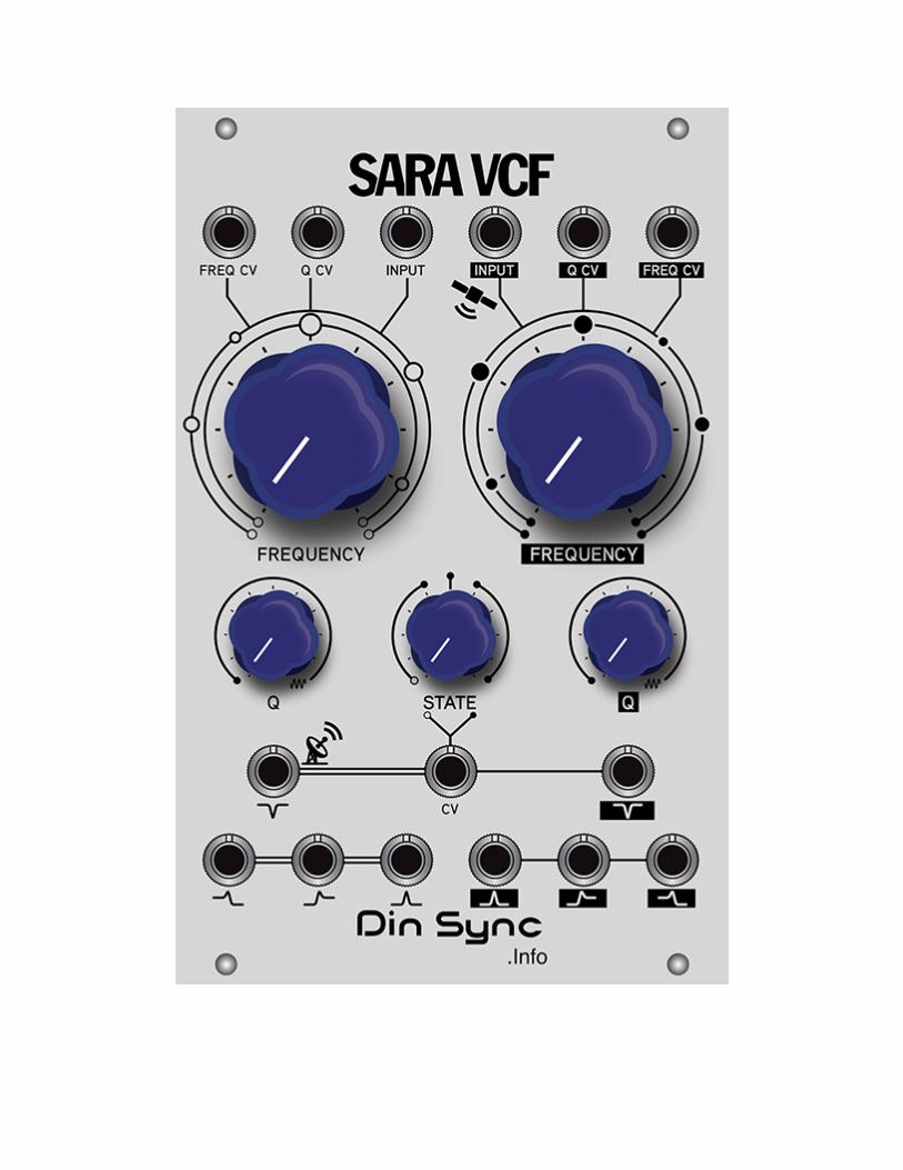

NOT JUST ANOTHER FILTER when approaching the SARA VCF, it’s best not to think of it as just another filter, or two filters in one. The design philosophy was to create a musical tool that would reward the user with time and effort. Take some time to explore the possibilities with external cv control, theres some weird shit in there I can tell you. Most filters are pretty easy to operate, however SARA VCF has a few things to note. The default routing is to plug a signal into core 1 input and take the output from core 2 notch, in this setup core 1 notch output is normalised to core 2 input and both cores are “opposed” That’s to say when core 1 is set to low pass (via the state control) core 2 will be high pass, and vice versa. When first using the notch modes its very easy to filter everything, resulting in no sound at all!! If this happens take a moment to check the positions of the frequency knobs, rotating them opposite (or the state) usually fixes things. Single core outputs will be inverted, this is to say that when using the cores as single filters the outputs are inverted. If the signal passes through both cores it will of course not be inverted any longer. When you have a control voltage connected to the Q or STATE cv inputs the knobs become attenuators. (this is not the case with the frequency knobs) The input/output ratio for both cores is slightly different, core 2 is more dampened since its considered the output stage and so is tamed a little. In use this will mean the output of core 1 is louder. If you want the best possible single filter response then core 1 should be used as it has roughly a 1:1 input/output ratio. The center frequency of each core can be adjusted to your taste, they have been adjusted to give an optimal range for the cutoff knobs. However this means that the filters will bleed slightly in low pass mode with the cutoff at zero. You can find more information about the adjustments in the calibration section of the manual. wow you read this far? I’m impressed. That’s probably pretty much all you need to get started and if you didn’t just jump in already, read on for a little more detail. Or skip forward to find some weird patches to try out for yourself!

SARA VCF each core features Control voltage input for cutoff 12/+12v Control voltage input for Q 0/+5v Control voltage for State 0/+5v (shared) Self oscillation, tracking 1v/oct for around 4 octaves key features Dual “opposing” cores where each core is a mirror state of the other. When one core’s state is swept fully low pass the other core is fully high pass. Control voltage for state works well into audio range. additional features Eight simultaneous outputs from various stages of routing Core two input is normalled from core one notch output. Can also be used as two independent filters. Each core has a different input/output response.


Patches
QuasiLPG set core1 Q to max (self oscillation) core1 FREQ sets base pitch set core2 FREQ to minimum set core2 Q to minimum set STATE to minimum connect an envelope with zero attack and a smooth decay (such as the VCF303 env out) to core2 FREQ CV using a cv/gate sequencer connect the sequencer pitch control voltage output to core1 FREQ CV and the gate output to the envelope take output from core2 LP In loving memory of Infradead’s chickens set core1 FREQ 9 o’clock set core2 FREQ 12 o’clock set Q1 max set Q2 max set STATE max patch core2 lp out to core 2 QCV in setup a maths (or equivalent) for two cycling log waves, speed will be the clucks, multi maths sum out to core1 FREQ CV core2 FREQ CV STATE CV take output from core2 NOTCH cluck cluck cluck waterfall trills same patch as above but increase maths speeds and patch core 2 bp out to core1 input

Engine room core1 freq 0% core1 res 100% state 100% core2freq 25% core2 res 90% patch osc3032 square out to core1 in, osc freq controls effect (adjust until beating around 80%) patch core1 hpout to state cv patch core2 lp out to core2 qcv take output from core2 notch Pete’s eel pie set both cores to self osc send two different quantised cvs to both freq cv ins (different sources for best results) input can be any wave (or none at all) set freq and state to taste take out from core2 notch Attack of the random squawks freq1 around 2 o clock freq2 12 o clock both res to max state a little off centre either way patch core 2 band pass out to core 1 freq cv patch core 1 band pass out to core 2 freq cv take output from core2 notch adjust freq knobs until feeback tone starts to squawk

dx fantasy set state to max set core 1 freq to 11oclock set core 2 freq to 9 oclock set core 1 q to max set core 2 q to 3 oclock osc303 MKII saw out to state cv in vcf303 env out to core 2 freq cv take output from core 2 lp out trigger vcf303 env and adjust vcf303 decay to taste Cylon pulse drive both freqs to 50% both q’s self osc state 100% patch core1 lp out to state cv osc3032 square wave to core 2 input output from core 2 notch

CALIBRATION PLEASE NOTE: Your module was already carefully calibrated, you should not attempt to, nor need to adjust the trimmers. MISADJUSTMENT WILL CAUSE MISOPERATION and readjustments are not covered by warranty. This information is provided as a courtesy and adjustments should only be made by a qualified technician.
Trimmer locations
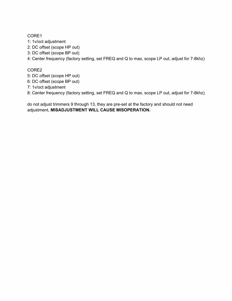
CORE1 1: 1v/oct adjustment 2: DC offset (scope HP out) 3: DC offset (scope BP out) 4: Center frequency (factory setting, set FREQ and Q to max, scope LP out, adjust for 78khz) CORE2 5: DC offset (scope HP out) 6: DC offset (scope BP out) 7: 1v/oct adjustment 8: Center frequency (factory setting, set FREQ and Q to max, scope LP out, adjust for 78khz) do not adjust trimmers 9 through 13, they are preset at the factory and should not need adjustment, MISADJUSTMENT WILL CAUSE MISOPERATION.

Acknowledgements
many thanks go out to Stephen Kwartler from http://www.promodular.com for the panel design. Chris “Infradead” Lehfeldt for beta testing, demonstrating and generally being awesome.
Specifications Width 16 HP Depth 35 mm, measured from the rear of the faceplate . 44 mm, measured from the rear of the faceplate to the edge of the supplied and connected power cable. Power consumption: max 45 ma +12 45 ma 12