installation and user guide dvr-ez - tlc-direct · press f(play button) to open the playback menu...
TRANSCRIPT
Installation And User GuideDVR-EZ
4 Channel Digital Video Recorder

Regulatory
FCC Certification This equipment has been tested and found to comply with the limits for a class A digital device, pursuant to Part 15 of the FCC rules. These limits are designed to provide reasonable protection against harmful interference when the equipment is operated in a commercial environment. This equipment generates, uses, and can radiate radio frequency energy and, if not installed and used in accordance with the instruction manual, may cause harmful interference to radio communications. Operation of this equipment in a residential area is likely to cause harmful interference in which case the user will be required to correct the interference a their own expense.
CE MarkThis product is marked with the CE symbol and indicates compliance with all applicable EEC directives.
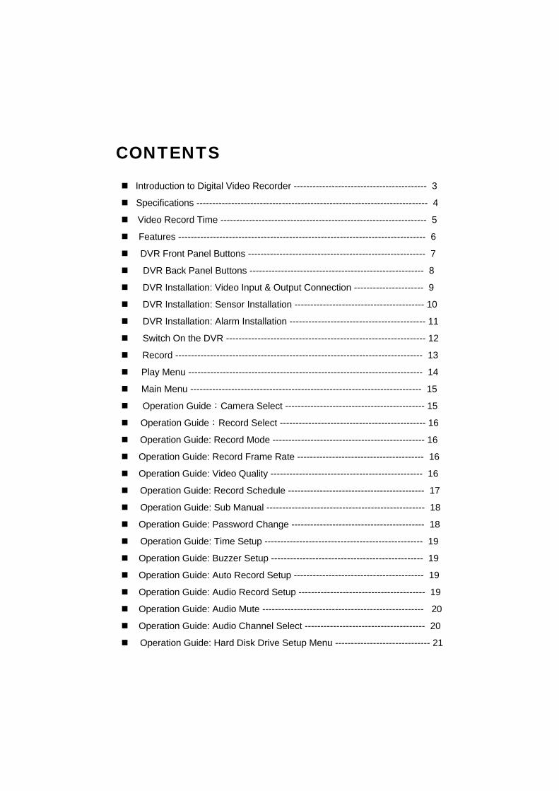
Introduction to Digital Video Recorder ------------------------------------------ 3
Specifications ------------------------------------------------------------------------- 4
Video Record Time ----------------------------------------------------------------- 5
Features ------------------------------------------------------------------------------ 6
DVR Front Panel Buttons -------------------------------------------------------- 7
DVR Back Panel Buttons ------------------------------------------------------- 8
DVR Installation: Video Input & Output Connection ---------------------- 9
DVR Installation: Sensor Installation ----------------------------------------- 10
DVR Installation: Alarm Installation ------------------------------------------- 11
Switch On the DVR --------------------------------------------------------------- 12
Record ------------------------------------------------------------------------------ 13
Play Menu -------------------------------------------------------------------------- 14
Main Menu ------------------------------------------------------------------------- 15
Operation Guide:Camera Select -------------------------------------------- 15
Operation Guide:Record Select ---------------------------------------------- 16
Operation Guide: Record Mode ------------------------------------------------ 16
Operation Guide: Record Frame Rate ---------------------------------------- 16
Operation Guide: Video Quality ------------------------------------------------ 16
Operation Guide: Record Schedule ------------------------------------------- 17
Operation Guide: Sub Manual -------------------------------------------------- 18
Operation Guide: Password Change ------------------------------------------ 18
Operation Guide: Time Setup -------------------------------------------------- 19
Operation Guide: Buzzer Setup ------------------------------------------------ 19
Operation Guide: Auto Record Setup ----------------------------------------- 19
Operation Guide: Audio Record Setup ---------------------------------------- 19
Operation Guide: Audio Mute --------------------------------------------------- 20
Operation Guide: Audio Channel Select -------------------------------------- 20
Operation Guide: Hard Disk Drive Setup Menu ------------------------------ 21
CONTENTS

Operation Guide: Overwrite -------------------------------------------- 21
Operation Guide: HDD Size & HDD Used -------------------------- 21
Operation Guide: HDD Format ---------------------------------------- 21
Sensor Set up ------------------------------------------------------------- 22
Motion Set up ------------------------------------------------------------- 23
USB to PC ----------------------------------------------------------------- 24
Print Event -----------------------------------------------------------------26
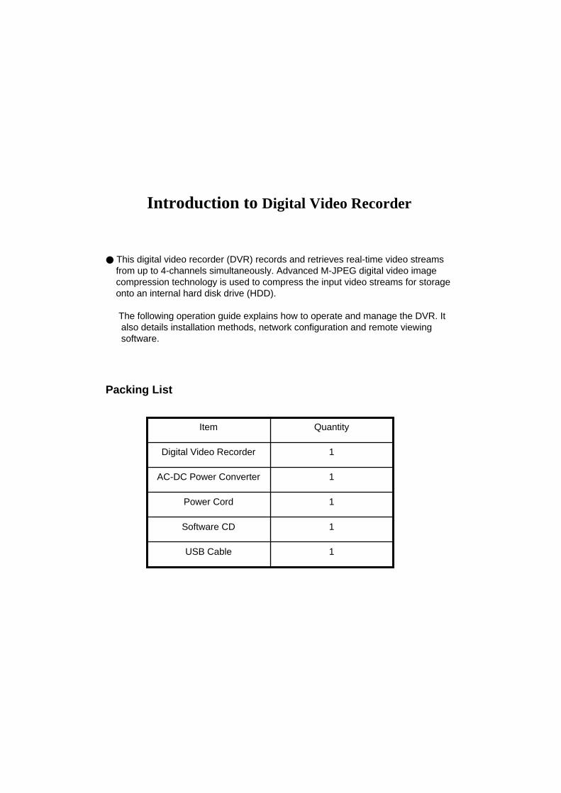
Introduction to Digital Video Recorder
● This digital video recorder (DVR) records and retrieves real-time video streamsfrom up to 4-channels simultaneously. Advanced M-JPEG digital video imagecompression technology is used to compress the input video streams for storageonto an internal hard disk drive (HDD).
The following operation guide explains how to operate and manage the DVR. Italso details installation methods, network configuration and remote viewingsoftware.
Packing List
1USB Cable
1Software CD
1Power Cord
1AC-DC Power Converter
1Digital Video Recorder
QuantityItem
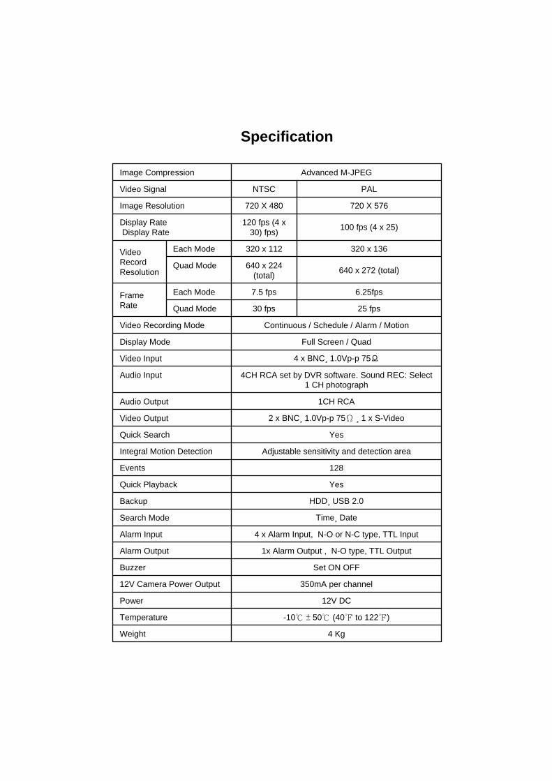
12V DCPower
4 Kg Weight
-10℃ ± 50℃ (40℉ to 122℉)Temperature
350mA per channel12V Camera Power Output
Set ON OFFBuzzer
1x Alarm Output , N-O type, TTL OutputAlarm Output
4 x Alarm Input, N-O or N-C type, TTL InputAlarm Input
Time¸ DateSearch Mode
HDD¸ USB 2.0Backup
YesQuick Playback
128Events
Adjustable sensitivity and detection areaIntegral Motion Detection
YesQuick Search
2 x BNC¸ 1.0Vp-p 75Ω ¸ 1 x S-VideoVideo Output
1CH RCAAudio Output
4CH RCA set by DVR software. Sound REC: Select 1 CH photograph
Audio Input
4 x BNC¸ 1.0Vp-p 75ΩVideo Input
Full Screen / QuadDisplay Mode
Continuous / Schedule / Alarm / MotionVideo Recording Mode
25 fps30 fpsQuad Mode
6.25fps7.5 fpsEach ModeFrame Rate
640 x 272 (total)640 x 224 (total)
Quad Mode
320 x 136320 x 112Each ModeVideo Record Resolution
100 fps (4 x 25)120 fps (4 x 30) fps)
Display RateDisplay Rate
720 X 576720 X 480Image Resolution
PALNTSCVideo Signal
Advanced M-JPEGImage Compression
Specification
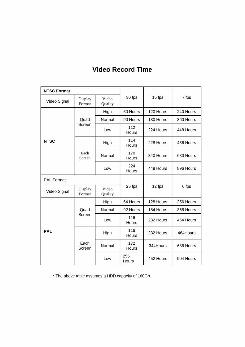
Video Record Time
904 Hours452 Hours256HoursLow
688 Hours344Hours172HoursNormal
464Hours232 Hours116HoursHigh
EachScreen
464 Hours232 Hours116HoursLow
368 Hours184 Hours92 HoursNormal
256 Hours128 Hours64 HoursHigh
QuadScreen
PAL
Video Quality
DisplayFormatVideo Signal
6 fps12 fps25 fpsPAL Format
896 Hours448 Hours224HoursLow
680 Hours340 Hours170HoursNormal
456 Hours228 Hours114HoursHigh
Each Screen
448 Hours224 Hours112HoursLow
360 Hours180 Hours90 HoursNormal
240 Hours120 Hours60 HoursHigh
QuadScreen
NTSC
Video Quality
DisplayFormatVideo Signal
7 fps15 fps30 fpsNTSC Format
.The above table assumes a HDD capacity of 160Gb.

Features
- Motion Detection on all four channels.
- Five levels of sensitivity on motion detection.
- Two adjustable motion detection fields per channel.
- Audio input on all four channels, single audio recording.
- Three levels of video quality.
- Four alarm inputs (either NO or NC). Single alarm output.
- Watchdog, recording automatically resumes after power loss.
- Quick search from time/date and event menu
- Stores up to 128 events of motion detection.
- Video Loss Buzzer, can be set to On or Off
- Password Protection.
- USB2.0 Support.
- Alarms when HDD is full : Displayed by OSD.
- 12V power output available for camera.

DVR Front Panel Operation Guide
1. Menu button:Press to display Operation menu option
2. 2. Up button:used in menu
3. All channels button:Press to display all channels
4. Channel 4 button:Press to display channel 4
5. Channel 3 button:Press to display channel 3
6. Channel 2 button:Press to display channel 2
7. Channel 1 button:Press to display channel 1
8. Reverse : Press to rewind playback
9. Pause button:Press to pause playback
10. Playback button:Press to start playback
11. Fast forward button:Press to play the recorded stream faster
12. Recording button: Press to start recording
13. Stop Recording / Stop Playback button:Press to stop recording or playback .The authorized password is requested upon stopping record .Default password is 111111
( Button 7 shown above; refer to page 18 )
14. Down button : used in menu
15. Select button:change the setting value or enter into a sub menu
16. USB Link Port
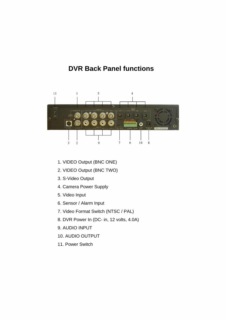
DVR Back Panel functions
1. VIDEO Output (BNC ONE)
2. VIDEO Output (BNC TWO)
3. S-Video Output
4. Camera Power Supply
5. Video Input
6. Sensor / Alarm Input
7. Video Format Switch (NTSC / PAL)
8. DVR Power In (DC- in, 12 volts, 4.0A)
9. AUDIO INPUT
10. AUDIO OUTPUT
11. Power Switch
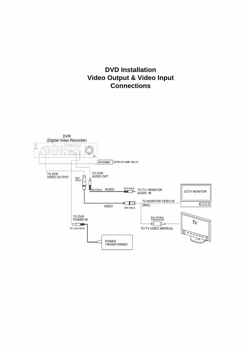
DVD InstallationVideo Output & Video Input
Connections
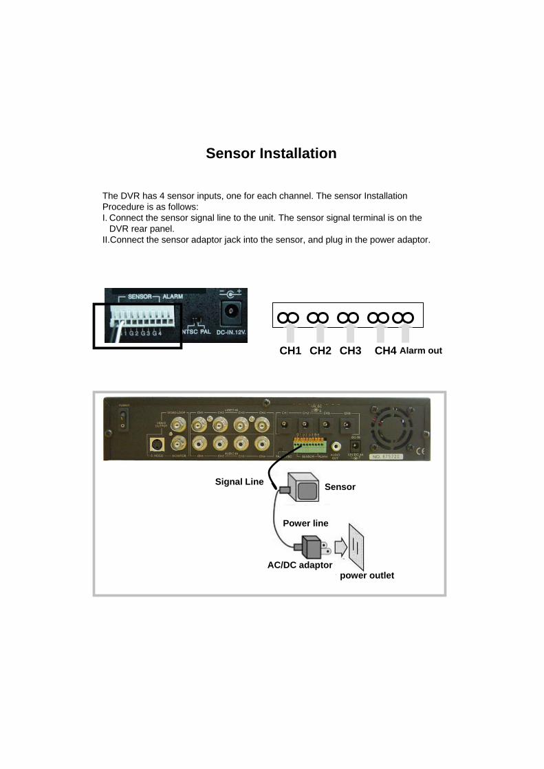
Sensor Installation
The DVR has 4 sensor inputs, one for each channel. The sensor Installation Procedure is as follows:I. Connect the sensor signal line to the unit. The sensor signal terminal is on the
DVR rear panel.II.Connect the sensor adaptor jack into the sensor, and plug in the power adaptor.
power outletAC/DC adaptor
Sensor
Power line
Signal Line
CH1 CH2 CH3 CH4 Alarm out

Alarm installation
The DVR includes one internal switch for sounding an alarm when any of thesensor inputs is activated. The switch is normally open and closed upon activation. The circuitry is shown in the above figure. The alarm is installed as follows:I.The alarm requires a power supply, which is normally supplied with the alarm.II.Connect the alarm power line to the alarm switch terminal on the rear of the DVR.
AlarmAC/DC adaptorpower outlet
Signal LinePower line

Once the DVR has been properly installed (please refer to pages 9 ~11 for further details on DVR installation) the unit is ready to record and display. Apply power and switch on.
Following power on, the DVR takes a few seconds checking the HDD. If a new hard drive is detected, the DVR will format the drive automatically. One of the below messages are displayed:
Press Pause button ( in front panel, page 18, will restore the unit to factory settings. “DVR Reset Completed” message will be displayed on the monitor and request the re-start of the DVR in order to make the changes effective.
On the completion of the re-start of DVR, the unit will start to operate. Users can display a quad view on the monitor (if four CCD camera are connected to the DVR) by pressing “All Channel Button”, button on the front panel (Refer to page 18). To see a specific display of connected CCD cameras, please press the “channel button” respectively to the channel the CCD camera is installed on the back panel.
Switch On the DVR
Before turn on the power, please make sure Video Format is in right positionNTSC Area : North America, Japan, Philippines, Taiwan & etc.PAL Area : Europe, South America, Australia, Mid-East & AfricaAsian Countries most use PAL like Indonesia, Thailand, Malaysia and etc.
HDD Checking …..Master 160072 MB.
HDD Checking …..Master160072MBNew HDD format completedSlaveNo HDD Detected
Record
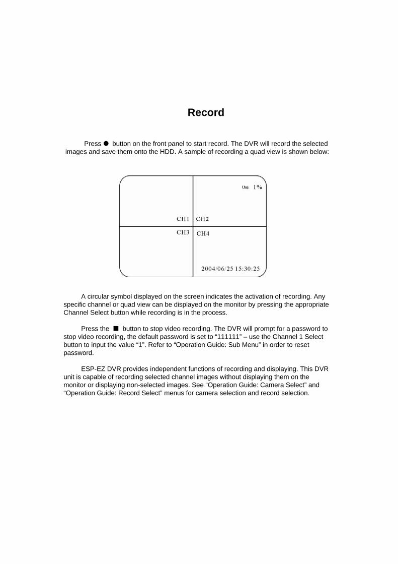
Press button on the front panel to start record. The DVR will record the selected images and save them onto the HDD. A sample of recording a quad view is shown below:
A circular symbol displayed on the screen indicates the activation of recording. Any specific channel or quad view can be displayed on the monitor by pressing the appropriate Channel Select button while recording is in the process.
Press the button to stop video recording. The DVR will prompt for a password to stop video recording, the default password is set to “111111” – use the Channel 1 Select button to input the value “1”. Refer to “Operation Guide: Sub Menu” in order to reset password.
ESP-EZ DVR provides independent functions of recording and displaying. This DVR unit is capable of recording selected channel images without displaying them on the monitor or displaying non-selected images. See “Operation Guide: Camera Select” and “Operation Guide: Record Select” menus for camera selection and record selection.

Play Menu
Press (play button) to open the playback menu as shown below.
List of events triggered by installed sensors or motion detection.
Available recordings in the HDD can be played.
Pressing button to start a time and date search.
Position the cursor using the ▲ and ▼ buttons to select the date and/or time. Use button to cycle through the available options. After reaching the desired option use the ▲and ▼ buttons to move onto the next variable. When the correct date and time has been entered press button to start the playback.
Use button to speed up the playback rate. Pressing twice doubles the playback speed. Pressing the button reverses the playback.
When the menu first appears the cursor is set to the first logged event. Press the button to playback that event or use the ▲ and ▼ buttons to select another listed event.
Press button to pause playback
Press button to stop playback.
HARD DRIVE:MASTER05/06/18 17:26:47-05/06/25 17:28:23
01 TIME 2005/06/18 17:26:4702 TIME 2005/06/19 17:25:4703 TIME 2005/06/19 20:03:50PRESS﹝∧,∨﹞THEN﹝SELECT﹞PRESS ﹝MENU﹞TO EXIT

MAIN MENUPress the button to display the main menu.
Use the ▼ and ▲ buttons to move the cursor up and down.Press to enter the selected sub-menu.Use the ▼ and ▲ buttons to position the cursor.Press to cycle through until reaching the desired option.Press to make the selection and return to the main directory. Press to return to real time display.
Operation Guide: CAMERA SELECT
Used to select and display (on the menu bar) the number of cameras connected to the DVR.The Video Loss buzzer is enabled if a camera is selected in this menu but there is no video signal present on that channel.
Use the to cycle through the options, some examples are shown below:(1 2 3 4):Cameras 1, 2, 3 and 4 have been selected. (12--):Cameras 1 and 2 have been selected. (-2 3-):Cameras 2 and 3 have been selected. (----): No cameras have been selected.
CAMERA SELECT 1234RECORD SELECT 1234RECORD MODE EACHRECORD FRAMERATE 30VIDEO QUALITY HIGH RECORD SCHEDULE=SUB MENU=HARD DRIVE SETUPSENSOR SETUPNETWORK SETUP
PRESS﹝∧,∨﹞THEN﹝SELECT﹞PRESS ﹝MENU﹞TO EXIT

Operation Guide: RECORD SELECT
Used to select the cameras whose video input will be recorded on the HDD. Desired cameras must be pre-selected in the “Camera Menu” in order to perform record properly. Use to cycle through the options. Press to make the selection and return to the main directory.
NOTE: Desired channels cannot be recorded properly if the corresponding cameras are not pre-selected in the “Camera Menu.”
Operation Guide: RECORD MODE
Can be set to either “EACH” or “QUAD”. When set to “EACH” all selected cameras (in the Record Select menu) are recording on the HDD in full screen. When set to “QUAD” all selected cameras (in the Record Select menu) are recorded on the HDD as a quad screen image.Use to cycle through the options. Press to make the selection and return to the main directory.
Operation Guide: RECORD FRAME RATE
The default value is 30 fps for NTSC and 25 fps for PAL. There are a number of different frame rate settings:NTSC: 30fps, 15fps, 10fps, 7fps, 5fps, 4fps, 3fps, 2fps, 1fpsPAL: 25fps, 12fps, 8fps, 6fps, 4fps, 3fps, 2fps, 1fpsThe higher the frame rate the more natural the video stream will look when it’s played back but will use the greatest amount of HDD storage.The frame rate is divided by the number of cameras selected in the Record Select menu, for example:If the frame rate is set to 25fps (PAL) and four cameras have been selected then each camera will be recorded at 6.25fps.Use to cycle through the options. Press to make the selection and return to the main directory.
Operation Guide: VIDEO QUALITY
There are three options for video quality, HIGH, NORMAL and LOW. The higher the video quality the clearer the recorded images will be but will use a greater amount of HDD storage. Use to cycle through the options. Press to make the selection and return to the main directory.
MAIN MENUCAMERA SELECT 1234RECORD SELECT 1234RECORD MODE 田RECORD FRAMERATE 30VIDEO QUALITY HIRECORD SCHEDULE SUB MENUHARD DRIVE SETUPSENSOR SETUP
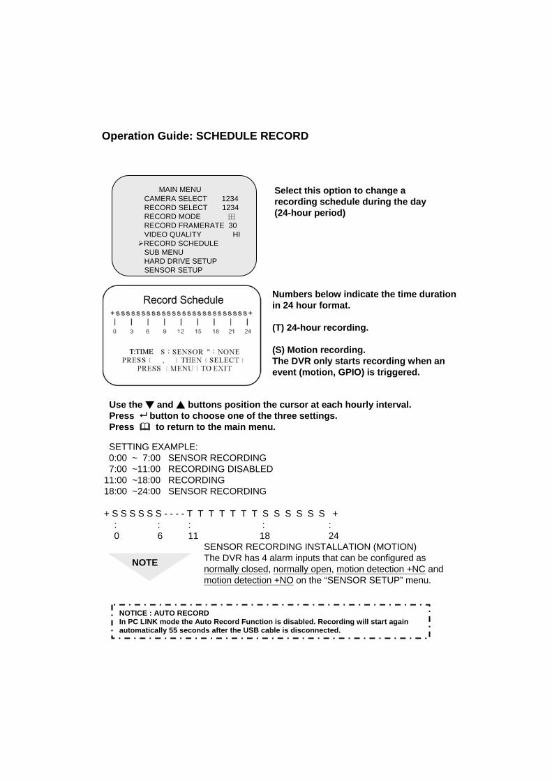
Select this option to change a recording schedule during the day (24-hour period)
Numbers below indicate the time durationin 24 hour format.
(T) 24-hour recording.
(S) Motion recording. The DVR only starts recording when an event (motion, GPIO) is triggered.
SETTING EXAMPLE:0:00 ~ 7:00 SENSOR RECORDING7:00 ~11:00 RECORDING DISABLED
11:00 ~18:00 RECORDING 18:00 ~24:00 SENSOR RECORDING
+ S S S S S S - - - - T T T T T T T S S S S S S +: : : : :0 6 11 18 24
NOTESENSOR RECORDING INSTALLATION (MOTION)The DVR has 4 alarm inputs that can be configured as normally closed, normally open, motion detection +NC and motion detection +NO on the “SENSOR SETUP” menu.
Operation Guide: SCHEDULE RECORD
NOTICE : AUTO RECORDIn PC LINK mode the Auto Record Function is disabled. Recording will start again automatically 55 seconds after the USB cable is disconnected.
Use the ▼ and ▲ buttons position the cursor at each hourly interval.Press button to choose one of the three settings.Press to return to the main menu.

Sub Menu allows users to change system password, system date and time, as well as various audio functions and auto record. Use ( ) to move cursor and select. Press ( ) to either cycle through the options or enter subsidiary menus.
SUB MENUPASSWORD CHANGETIME SETBUZZER SOUND [OFF]AUTO RECORD [OFF]AUDIO RECORD [ON]AUDIO OUT MUTE [OFF]AUDIO CHANNEL [1]
In the situation of requesting stop recording or HDD format, the DVR prompt for password to perform.
Select “PASSWORD CHANGE” - Its subsidiary menu (Left side figure) replaces the “SUB MENU”(the default password is 111111)
Enter the requested data.
NOTE FRONT PANEL BUTTONS DEFINITION means “1” means “5”
means “6”means “2” means “7”
means “8”means “3” means “9”means “4” means “0”
PASSWORD CHANGECURRENT PASSWORD: -------NEW PASSWORD:-------PASSWORD CONFIRM:--------
NOTICE: WHAT IF I FORGET PASS WORD?
If the password is mislaid or forgotten press the (∥) Pause button 5 times, which returns the DVR to the default setting(11111). The password can then be changed again.
Operation Guide: SUB MENU
Operation Guide: PASSWORD CHANGE

▼ and ▲ -- Position Year, Month, Day, Hour, Minute or Seconds.
-- Cycle through options (0,1,2 …9)
-- Exit
TIME
2004/03/21 03:23:21
PRESS ( ), THEN (SELECT )PRESS(MENU) TO EXIT
BUZZER :ON
Use the ▼ and ▲ to select buzzer optionsPress to choose ON/OFF. Press to return to the main menu.
ON: DVR buzzer sounds when videoloss is detected on any of thecameras selected in the “Record Select” menu
AUTO RECORD :ONPress to choose ON/OFF. Press to return to the main
menu.
ON: DVR records automatically after one minute even DVR is under display mode.
AUDIO RECORD :ONUse the ▼ and ▲ to select audio record optionsPress to choose ON/OFF. Press to return to the main menu.
ON: DVR records audio from selected channel.
Operation Guide: TIME SETUP
Operation Guide: BUZZER SETUP
Operation Guide: AUTO RECORD SETUP
Operation Guide: AUDIO RECORD SETUP

Use ▼ and ▲ to select audio out mute. Press to choose ON/OFF. Press to return to the main menu.
AUDIO OUT MUTE :ON
AUDIO CHANNEL : 1
Use ▼ and ▲ to select audio channel. Press to cycle through options.
(Channel 1,2,3,4)Press to return to the main menu.
DVR only records one channel of audio.
Operation Guide: AUDIO CHANNEL SELECT
Operation Guide: AUDIO MUTE

HARD DRIVE SETUPOVERWRITE ENABLED YESMASTER HDD SIZE 160000MBMASTER HDD USED 0MB 0%MASTER HDD FORMAT SLAVE HDD SIZE N/ASLAVE HDD USED N/ASLAVE HDD FORMAT
PRESS (<,>) THEN (SELECT)PRESS (MENU) TO EXIT
Hard Disk Drive Setup Menu
Operation Guide: OVER WRITE
“YES”. The DVR will record continuously and overwrite the recorded data when the HDD is full. “NO”. The unit will stop recording once the HDD is full.
Use ▼ and ▲ to select OVERWRITE ENABLED. Press to choose YES/NO. Press to return to the SUB menu.
Operation Guide: HDD SIZE AND HDD USED
Displays the storage capacity of the Master (and if installed the Slave HDD) and the amount of Storage used.
Operation Guide: HDD FORMAT
Use the▼ and ▲ buttons to select the “HDD Format” optionUse the button to select the format option. The system prompts for a password. If the password is accepted the format will commence and delete all images stored on the selected HDD. If an incorrect password is entered the system will display a message showing “Password Incorrect” and return to the Hard Drive Setup menu.

SENSOR SETUP MENU
SENSOR RECORD TIME: Recording duration once sensor Being triggered. Selects record time from 0 ~180 seconds.
ALARM OUT TIME:It controls how long ( in second)the alarm sounds after being triggered.Selects alarm ON time from 0 ~ 30 or continuous.
SENSOR SET UP
Use the▼ and ▲ buttons to select channels 1 ~ 4.Use the button to select options (Normal Open/Close)Press the button to exit
In normal open modethe cable line Connected between the sensor and the unit is cut off by an intruder, the unit starts recording.
In normal close mode, the cable line connected between the sensor and the Unit is cut off by an intruder , the unit stops recording.
SENSOR SETUPSENSOR RECORD TIME 15ALARM ON TIME 20
SENSOR SET UPMOTION SETUP
PRESS (<,>) THEN (SELECT)PRESS (MENU) TO EXIT
SENSOR SETUP
CHANNEL-1 NOT INSTALLCHANNEL-2 TYPE:NORMAL-OPENCHANNEL-3 TYPE:NORMAL-CLOSECHANNEL-4 TYPE:NORMAL-OPEN
PRESS (<,>) THEN (SELECT)PRESS (MENU) TO EXIT
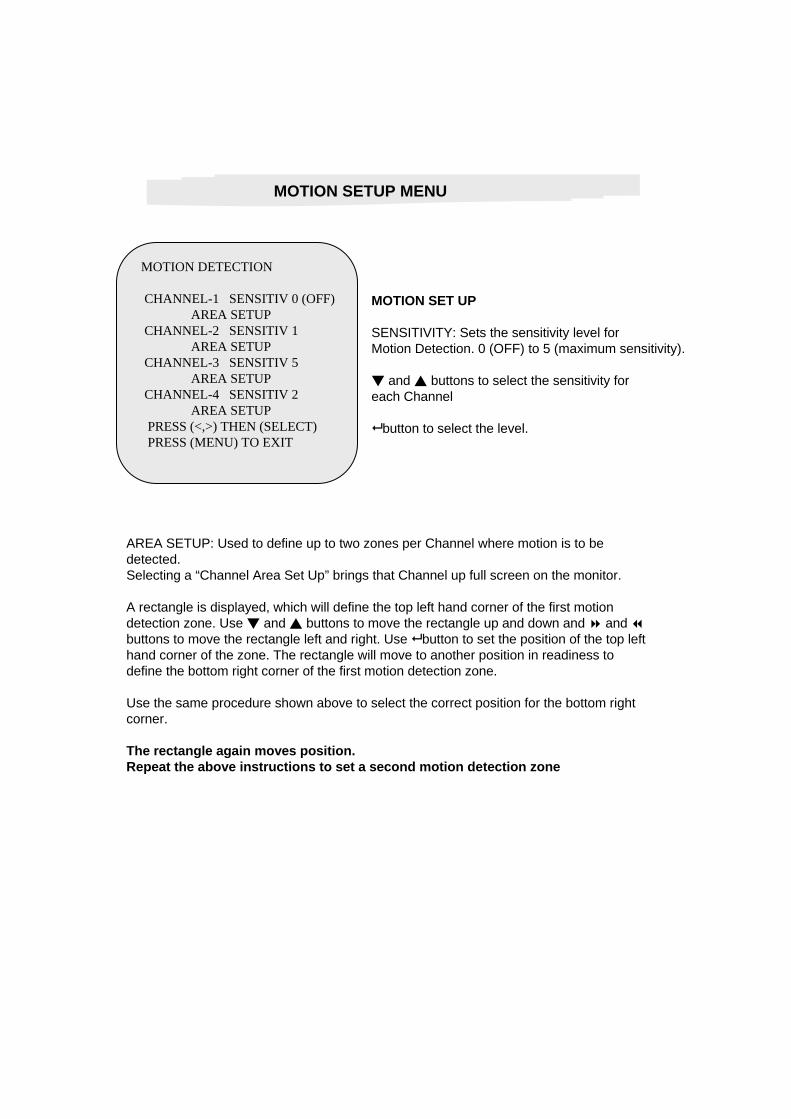
MOTION DETECTION
CHANNEL-1 SENSITIV 0 (OFF)AREA SETUP
CHANNEL-2 SENSITIV 1AREA SETUP
CHANNEL-3 SENSITIV 5AREA SETUP
CHANNEL-4 SENSITIV 2AREA SETUP
PRESS (<,>) THEN (SELECT)PRESS (MENU) TO EXIT
MOTION SET UP
SENSITIVITY: Sets the sensitivity level forMotion Detection. 0 (OFF) to 5 (maximum sensitivity).
▼ and ▲ buttons to select the sensitivity for each Channel
button to select the level.
AREA SETUP: Used to define up to two zones per Channel where motion is to be detected.Selecting a “Channel Area Set Up” brings that Channel up full screen on the monitor.
A rectangle is displayed, which will define the top left hand corner of the first motiondetection zone. Use ▼ and ▲ buttons to move the rectangle up and down and and buttons to move the rectangle left and right. Use button to set the position of the top left hand corner of the zone. The rectangle will move to another position in readiness to define the bottom right corner of the first motion detection zone.
Use the same procedure shown above to select the correct position for the bottom right corner.
The rectangle again moves position. Repeat the above instructions to set a second motion detection zone
MOTION SETUP MENU
How to Backup through USB port to PC
Backup through USB port
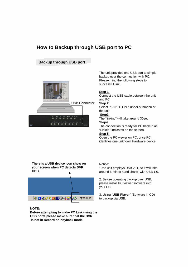
The unit provides one USB port to simple backup over the connection with PC. Please mind the following steps to successful link.
Step 1.Connect the USB cable between the unit and PC Step 2.Select “LINK TO PC” under submenu of the unitStep3.The “linking” will take around 30sec.Step4.The connection is ready for PC backup as “Linked” indicates on the screen. Step 5.Open the PC viewer on PC, once PC identifies one unknown Hardware device
Notice:1.the unit employs USB 2.O, so it will take around 5 min to hand shake with USB 1.0.
2. Before operating backup over USB, please install PC viewer software into your PC.
3. Using “USB Player” (Software in CD) to backup via USB.
There is a USB device icon show on your screen when PC detects DVR HDD.
NOTE:Before attempting to make PC Link using the USB ports please make sure that the DVRis not in Record or Playback mode.

Hints:When PC detects USB storage setup, PC has connected DVR host already. Switch on PC LINKplay program for 20~30 seconds, you can see following footage.
If there is no picture, HDD is not detected. Close the software of USB LINK and disconnect the USB cable. Five seconds later , connect the USB cable again. When the USB device is detected by the system , run USB LINK software.
9. Channel selection10. BMP picture file11. Copy MYS file12. Copy AVI file13. MYS player14. SOUND ON/OFF15. Video search bar
1. Fast rewind2. Play next frame3. Rewind4. Pause5. Play6. Play previous play7. Fast forward8. EVENT Search
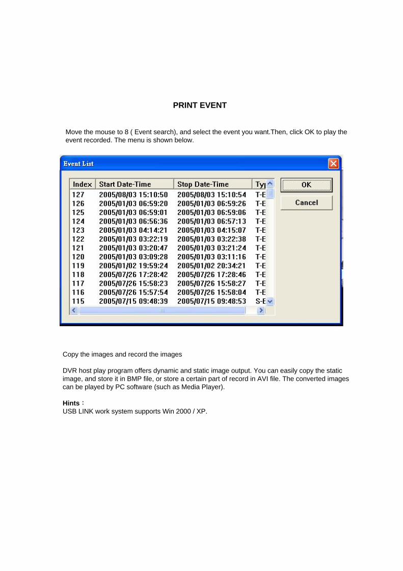
PRINT EVENT
Move the mouse to 8 ( Event search), and select the event you want.Then, click OK to play the event recorded. The menu is shown below.
Copy the images and record the images
DVR host play program offers dynamic and static image output. You can easily copy the static image, and store it in BMP file, or store a certain part of record in AVI file. The converted imagescan be played by PC software (such as Media Player).
Hints:USB LINK work system supports Win 2000 / XP.

Technical Support
0121 7861881