installation and use instructions - tauitalia.com · attachment i: 1.5.1 electrical power, 1.5.2...
TRANSCRIPT

1MF30
INSTALLATION AND USE INSTRUCTIONS
MF30Chain actuator for window automation
Via Enrico Fermi, 43 - 36066 Sandrigo (VI) ItaliaTel +39 0444 750190 - Fax +39 0444 750376
[email protected] - www.tauitalia.com
GB - Translation of original instructions
D-M
NL0
MF3
0-G
B 1
5-11
-201
7 -
Rev.
09
BEFORE INSTALLING AND USING THE ACTUATOR, IT ISCOMPULSORY FOR THE INSTALLER AND THE USER TO READ
AND UNDERSTAND THIS MANUAL IN ALL ITS PARTS.
THIS MANUAL IS INTEGRAL PART OF THE ACTUATORAND MUST BE PRESERVED FOR FUTURE REFERENCE
UNTIL DEMOLITION OF THE SAME.

2 MF30
1- DECLARATION OF “CE” CONFORMITY pag. 03
2- GENERAL REMARKS2.1- General instructions pag. 042.2- Installer and user pag. 042.3- Warranty pag. 042.4- Technical assistance pag. 042.5- Reserved rights pag. 042.6- Description of personnel pag. 05
3- TECHNICAL DESCRIPTION3.1- Rating plate and “CE” marking pag. 053.2- Denomination of the components and dimensions pag. 063.3- Technical data pag. 073.4- Formulas for the calculation of thrust force or tractive force pag. 083.5- Destination of use pag. 083.6- Use Limits pag. 093.7- Package pag. 09
4- SAFETY4.1- General instructions pag. 114.2- Safety Devices pag. 11
4.2.1- Protections against electric hazard pag. 114.3- Safety plates pag. 124.4- Residual risks pag. 12
5- INSTALLATION5.1- General instructions pag. 135.2- Top hung windows pag. 165.3- Bottom hung windows pag. 175.4- Electrical Connections pag. 195.5- Control devices pag. 205.6- Adjustment of the window frame closing pag. 205.7- Emergency procedures pag. 21
6- USE AND OPERATION6.1- Use of the actuator pag. 22
7- MAINTENANCE7.1- General instructions pag. 23
8- DEMOLITION8.1- General instructions pag. 23
9- SPARE PARTS AND ACCESSORIES UPON REQUEST9.1- General instructions pag. 23
FIGURES pag. 25
GUARANTEE pag. 30

3MF30
MANUFACTURER’S DECLARATION OF INCORPORATION(in accordance with European Directive 2006/42/EC App. II.B)
Manufacturer: TAU S.r.l.
Address: Via E. Fermi, 4336066 Sandrigo (Vi)ITALY
Declares under its sole responsibility, that the product: Chain Electromechanical Actuatordesigned for automatic movement of: Windowsfor use in a: Residential / Communitiescomplete with: -
Model: MF30Type: MF30 - 230 VSerial number: see silver labelCommercial name: Chain actuator for window automation
Has been produced for incorporation on an access point (window) of for assembly with other devices used to move such an access point, to constitute a machine in accordance with the Machinery Directive 2006/42/EC.Attachment I: 1.5.1 Electrical power, 1.5.2 Static power, 1.5.10 Radiations, 1.5.11 external radiations
Also declares that this product complies with the essential safety requirements of the following EEC directives:
- 2014/35/EU Low Voltage Directive- 2014/30/EU Electromagnetic Compatibility Directive
Also declares that it is not permitted to start up the machine until the machine in which it is incorporated or of which it will be a component has been identified with the relative declaration of conformity with the provisions of Directive 2006/42/EC.
The following standards and technical specifications are applied:EN 61000-6-2; EN 61000-6-3; EN 60335-1; EN 300 220-2 V2.4.1; EN 12453:2000; EN 12445:2000; EN 60335-2-103.
The manufacturer undertakes to provide, on sufficiently motivated request by national authorities, all information pertinent to the quasi-machinery.
Sandrigo, 15/11/2017
Legal Representative
_________________________________________Loris Virgilio Danieli
Name and address of person authorised to draw up all pertinent technical documentation:
Loris Virgilio Danieli - via E. Fermi, 43 - 36066 Sandrigo (Vi) Italy

4 MF30
2- GENERAL REMARKS
2.1- GENERAL INSTRUCTIONS
BEFORE INSTALLING AND USING THE ACTUATOR, IT IS COMPULSORY THAT THE INSTALLER AND THE USER CAREFULLY READ AND UNDERSTAND THIS MANUAL IN ALL ITS PARTS.
THIS MANUAL IS INTEGRAL PART OF THE ACTUATOR AND MUST COMPUL-SORILY BE PRESERVED FOR FUTURE REFERENCE.
THE MANUFACTURER HAS NO LIABILITY FOR ANY EVENTUAL DAMAGE TO PERSONS, ANIMALS AND THINGS DUE TO THE INOBSERVANCE OF THE PRE-SCRIPTIONS DESCRIBED IN THIS MANUAL.
2.2- INSTALLER AND USER
THE ACTUATOR INSTALLATION CAN BE PERFORMED EXCLUSIVELY BY COMPETENT AND QUALIFIED TECHNICAL PERSONNEL SATISFYING THE PROFESSIONAL AND TECHNICAL REQUIREMENTS FORESEEN BY THE LAWS IN FORCE IN THE COUNTRY OF INSTALLATION.
THE ACTUATOR CAN BE USED EXCLUSIVELY BY A USER ACTING IN COMPLI-ANCE WITH THE INSTRUCTIONS CONTAINED IN THIS MANUAL AND/OR IN THE MANUAL OF THE ACTUATOR CONTROL DEVICE (e.g.: CONTROL UNIT).
2.3- WARRANTY
THE ACTUATOR WARRANTY EXPIRES, IF ITS USE DOES NOT COMPLY WITH THE INSTRUCTIONS AND PRESCRIPTIONS DESCRIBED IN THIS MANUAL, AS WELL AS IF NON-ORIGINAL COMPONENTS, ACCESSORIES, SPARE PARTS, AND CONTROL SYSTEMS ARE USED.
2.4- TECHNICAL ASSISTANCEFor the technical assistance apply to your Dealer or to the Manufacturer.
2.5- RESERVED RIGHTSThe reserved rights on this manual “Installation and use instructions” remain property of the Manufacturer.Each information herein contained (text, drawings, diagrams, etc.) is reserved. None part of this manual can be reproduced and disclosed (totally or partially) by any reproduction means (pho-tocopies, microfilms or other) without written authorization of the Manufacturer.

5MF30
2.6- DESCRIPTION OF PERSONNEL
USERS MUST NEVER PERFORM OPERATIONS RESERVED FOR MAINTE-NANCE PEOPLE OR SPECIALISED TECHNICIANS. THE MANUFACTURER DE-CLINES ALL LIABILITY FOR DAMAGE DERIVING FROM FAILURE TO OBSERVE THE ABOVE REQUIREMENTS.
Specialised electrician:A specialised electrician must be able to install the actuator, start it and operate it both in normal conditions and in the maintenance mode; he/she is qualified to perform all electrical and me-chanical adjustment and maintenance operations. He/she is allowed to work on live electrical cabinets and junction boxes.
User:specialised person capable of operating the actuator under normal conditions by using the rela-tive controls. He/she must also be able to operate with the actuator under “maintenance” in or-der to perform simple routine maintenance operations (cleaning), and start or reset the actuator following an unscheduled stop.
3- TECHNICAL DESCRIPTION
3.1- RATING PLATE AND “CE” MARKING
The “CE” marking certifies the compliance of the machine with the essential safety and health requirements foreseen by the product European Directives.The rating plate is an adhesive plate in polyester, silk-screen printed in black, having the follow-ing size: L= 50 mm - H= 36 mm.It is applied externally on the actuator. The plate (Fig. 1) bears in readable and indelible way the following data:
• logo and address of the manufacturer • type and model • voltage and intensity of power supply (V - A)• type of service S2 (min)• absorbed electric power P (W)• thrust and tractive force F (N)• idle translation speed (mm/s)• protection degree (IP)• “CE” marking• symbol of “WEEE” Directive 2002/96/CE• serial number• month/year of construction
Fig.1

6 MF30
3.2- DENOMINATION OF THE COMPONENTS AND DIMENSIONS
Dimensions in mmFig.2
LEGEND:
1) 2) Slot side indicator3) Bracket for bottom hung opening4) Opening stroke adjustment
switch I= 200 mm; II= 380 mm5) Connection bracket to the frame6) Actuator7) Chain adjustment end8) Chain end adjustment screw 9) Power supply cable
Quick coupling
9
7
8
6
80
335.
2101
5
3
103
96.5
6.5
1.5
34.1220
11
Ø5
Ø5
11
5419
4
2
1
16
8615
4
49
37
46
53 46
1 12 12 7
310
276

7MF30
3.3- TECHNICAL DATA
Tab. 1 contains the technical data characterising the actuators.
MF30/230VPower supply voltage 230 V ~ 50 HzAbsorbed current 0,26 AAbsorbed power with load 60 WMaximum applicable thrust load 300 NMaximum applicable tractive load 300 NIdle translation speed 27 mm/sDuration of maximum idle stroke 14 sEnd of stroke selected at mm 200 380
Minimum height H (mm)of the window frame
Pos
ition
asse
mbl
ybr
acke
ts (1
) 0Top hung 250 400
Bottom hung 500 10001 Top hung 250 4002 Top hung 350 5003 Bottom hung 500 950
Minimum window frame height (2) H= 500 ÷ 950 mmEnd of stroke selectable at (3) 200 ÷ 380Protection against electric shocks Class IIIType of service S2 (4) 4 minOperating temperature -5°C +50°CProtection degree of electric devices IP 30
Adjustment of the window frame connection 0÷22,5 mm (Top hung)0÷30 mm (Bottom hung)
Parallel electric connection of moreactuators on the same window
Only with properelectronic device
Parallel electric connection of moreactuators on different windows
Yes(see wiring diagram)
Actuator weight with brackets 1,1 kgGross weight 1,5 kgElectronics with warning horn to signal to the user the wrong assembling (5)
(1) For the assembly position of the brackets see Fig. 7(2) Distance of the actuator from the window opening hinge valid only with max. stroke 380 mm(3) Tolerance on the tripping precision of the limit switch at output: ± 10 mm(4) Service of limited duration according to EN 60034(5) The “buzzer” device enables automatically itself emitting a continuous “beep” as long as the
actuator is supplied. For further details on the operation see par.5.6
Tab.1

8 MF30
3.4- FORMULAS FOR THE CALCULATION OF THRUST AND TRACTIVE FORCE
Fig.3
Horizontal domes or skylights
F = Force necessary for opening or closing
P = Weight of the skylight or dome (only movable part)
F = 0,54 x P
F
P
Fig.4
P
F
H
CB
PF
H
C
ATop hung windows (A) or bottom hung windows (B)
F = Force necessary for opening or closingP = Weight of the window (only movable
part)C = Window opening strokeH = Window height (only movable part)
F = (0,54 x P) x (C / H)
3.5- DESTINATION OF USE
THE ACTUATOR HAS BEEN DESIGNED AND MANUFACTURED TO PERFORM AUTOMATICALLY, BY MEANS OF A CONTROL DEVICE, THE OPENING AND CLOSING OF TOP HUNG WINDOWS, BOTTOM HUNG WINDOWS, PIVOT WIN-DOWS, AND SKYLIGHTS.

9MF30
3.6- USE LIMITS
The actuator has been designed and manufactured exclusively for the destination of use given in par. 3.5, therefore, any other type of use is strictly forbidden in order to assure in any moment the safety of the installer and of the user, as well as the efficiency of the actuator itself.
IT IS STRICTLY FORBIDDEN TO USE THE ACTUATOR FOR IMPROPER USES OTHER THAN THE ONE FORESEEN BY THE MANUFACTURER (SEE PAR. 3.5).
IT IS STRICTLY FORBIDDEN TO INSTALL THE ACTUATOR ON THE EXTERNAL SIDE OF THE WINDOW FRAME SUBJECT TO ATMOSPHERIC AGENTS (RAIN, SNOW, ETC.).
THE USE OF THE ACTUATOR IN ENVIRONMENTS WITH POTENTIALLY EXPLO-SIVE ATMOSPHERE IS STRICTLY FORBIDDEN.
IT IS COMPULSORY TO KEEP THE PACKAGE AND THE ACTUATOR OUT OF REACH OF CHILDREN.
3.7- STANDARD PACKAGE
Each standard package of the product (cardboard box) contains (Fig.5):• No.1 Actuator equipped with power supply cable;;• No.1 Window frame connection bracket (Ref.A);• No.1 Bracket for bottom hung opening (Ref.B);• No.1 Small parts package (quick coupling, No.2 bracket fastening lateral screws, No.7
screws AF Ø 4.2 x 19 mm for fastening the bracket to the window frame (Ref.C);• No.1 (2 mm) Allen wrench (Ref. D)• No.1 Installation and use instructions (Ref.E)• No.1 Safety Plate (Fig.6).
MAKE SURE THAT THE ABOVE DESCRIBED COMPONENTS ARE CONTAINED IN THE PACKAGE, AS WELL AS THAT THE ACTUATOR HAS NOT BEEN DAM-AGED DURING TRANSPORT.
SHOULD ANY ANOMALY BE DETECTED, IT IS FORBIDDEN TO INSTALL THE ACTUATOR, AND IT IS COMPULSORY TO REQUIRE TECHNICAL ASSISTANCE FROM YOUR DEALER OR THE MANUFACTURER.
THE PACKAGING (PAPER, PLASTIC, ETC.) HAS TO BE DISPOSED ACCORD-ING TO THE LAWS IN FORCE.

10 MF30
Fig.5
A
B C
ED

11MF30
4- SAFETY
4.1- GENERAL INSTRUCTIONS
OPERATORS MUST BE INFORMED OF ACCIDENT RISKS, SAFETY DEVICES AND THE GENERAL ACCIDENT PREVENTION REGULATIONS ESTABLISHED BY INTERNATIONAL DIRECTIVES AND BY THE LAW IN FORCE IN THE COUN-TRY OF USE.ALL OPERATORS MUST STRICTLY COMPLY WITH THE ACCIDENT PREVEN-TION REGULATIONS IN FORCE IN THE COUNTRY OF USE.
DO NOT REMOVE OR ALTER THE PLATES PLACED ON THE ACTUATOR BY THE MANUFACTURER.
IF THE WINDOW FRAME IS ACCESSIBLE FROM OR INSTALLED AT A HEIGHT OF LESS THAN 2.5 m FROM THE GROUND, AND IF IT CAN BE COMMANDED BY AN UNTRAINED USER OR WITH A REMOTE CONTROL DEVICE, FIT AN EMERGENCY STOP SYSTEM WHICH AUTOMATICALLY CUTS IN TO PREVENT THE RISK OF CRUSHING OR DRAGGING PARTS OF THE BODY INSERTED BE-TWEEN THE MOVING AND FIXED PARTS OF THE WINDOW FRAME.
ANY TAMPERING WITH OR UNAUTHORISED REPLACEMENT OF ONE OR MORE PARTS OR COMPONENTS OF THE ACTUATOR, OR THE USE OF UN-ORIGINAL ACCESSORIES AND CONSUMABLES, MAY INCREASE THE RISK OF ACCIDENT AND THUS RELIEVES THE MANUFACTURER OF ALL CIVIL AND PENAL LIABILITY.
EXTRAORDINARY AND ROUTINE MAINTENANCE OPERATIONS INVOLVING THE TOTAL OR PARTIAL DISMOUNTING OF THE ACTUATOR MAY ONLY BE PERFORMED AFTER DISCONNECTING IT FROM THE POWER SUPPLY.
THIS APPLIANCE MAY NOT BE USED BY PERSONS (CHILDREN INCLUDED) WITH REDUCED PHYSICAL, SENSORIAL OR MENTAL CAPACITIES, OR INEX-PERT PEOPLE, UNLESS THEY ARE SUPERVISED AND TAUGHT HOW TO USE IT BY A PERSON RESPONSIBLE FOR THEIR SAFETY. CHILDREN MUST BE CONTROLLED TO MAKE SURE THEY DO NOT PLAY WITH THE APPLIANCE.
4.2- SAFETY DEVICES
4.2.1- PROTECTION AGAINST ELECTRIC HAZARD
The actuator is protected against electric hazard due to direct and indirect contacts.The protection measures against direct contacts aim at protecting people against hazards due to contact with active parts, usually live parts; while the protection measures against indirect contacts aim at protecting people against hazards due to conducing part, which are usually insulated, but could become live in case of failure (insulation failure).

12 MF30
The adopted protection measures are the following:1) Insulation of live parts by means of a plastic material body;2) Enclosure with suitable protection degree;
4.3- SAFETY PLATES
IT IS FORBIDDEN TO REMOVE, MOVE, SPOIL OR IN ANYWAY REDUCE THE VISIBILITY OF THE SAFETY PLATES. FAILURE TO OBSERVE THE ABOVE MAY CAUSE SERIOUS HARM TO PEOPLE AND DAMAGE TO PROPERTY. THE MAN-UFACTURER DECLINES ALL LIABILITY FOR ANY DAMAGE CAUSED BY THE FAILURE TO OBSERVE THE ABOVE REQUIREMENT.
Fig. 6 illustrates the safety plate: this must applied directly to the outside of theactuator or near it and always in a position where it can be seen by the installer and/oroperator.
4.4- RESIDUAL RISKS
The installer and the user are herewith informed that after the actuator has been installed on the window, the actuator drive can accidentally generate the following residual risk:
Residual risk:Hazard of squashing or dragging of body parts inserted between the movable and the fix part of the window frame.
Exposure frequency: Accidental and when the installer or the user decides to perform a wrong voluntary action.
Severity of the damage:Light lesions (usually reversible).
Adopted measures:Before enabling the device, it is compulsory to verify that near the window there are not persons, animals or things whose safety may be accidentally jeopardized. During actuator operation, it is compulsory to be in a safe control position assuring visual control on the window movement.
Fig.6MACCHINA AD AVVIAMENTO AUTOMATICOAUTOMATIC MACHINE
PERICOLO ATTENZIONE ALLE MANI BEWARE OF YOUR HANDS
ATTENZIONE MACCHINA AD AVVIAMENTO AUTOMATICO CON COMANDO A DISTANZAATTENTION! AUTOMATIC MACHINE WITH REMOTE CONTROL DEVICE
IT
EN
PRIMA DI INSTALLARE E UTILIZZARE L’ATTUATORE È OBBLIGATORIO CHE L’INSTALLATORE E L’UTILIZZATORE LEGGANO E COMPRENDANO IN TUTTE LE SUE PARTI IL MANUALETHE INSTALLER AND USER MUST READ AND UNDERSTAND ALL PARTS OF THIS MANUAL BEFORE INSTALLING AND USING THE ACTUATOR

13MF30
5- INSTALLATION
5.1- GENERAL INSTRUCTIONS
THE ACTUATOR INSTALLATION CAN BE PERFORMED EXCLUSIVELY BY COMPETENT AND QUALIFIED TECHNICAL PERSONNEL SATISFYING THE PROFESSIONAL AND TECHNICAL REQUIREMENTS FORESEEN BY THE LAWS IN FORCE IN THE COUNTRY OF INSTALLATION.
THE ACTUATOR PERFORMANCE MUST BE SUFFICIENT TO ASSURE THE CORRECT MOVEMENT OF THE WINDOW. IT IS COMPULSORY TO VERIFY THE THRUST OR TRACTIVE FORCE ACCORDING TO THE TYPE AND WEIGHT OF THE WINDOW (PAR. 3.4).IT IS FORBIDDEN TO EXCEED THE LIMITS GIVEN IN TAB. 1 CONCERNING THE TECHNICAL DATA (PAR. 3.3).
THE ACTUATOR INSTALLATION MUST BE PERFORMED EXCLUSIVELY WITH CLOSED WINDOW OR SKYLIGHT.
BEFORE PERFORMING THE INSTALLATION OF THE ACTUATOR ON HOPPERWINDOWS, VERIFY THAT ON BOTH SIDES OF THE WINDOW TWO COMPASS STROKE LIMIT DEVICES ARE INSTALLED IN ORDER TO AVOID THE ACCIDEN-TAL FALL OF THE WINDOW.
FOR CORRECT OPERATION OF THE ACTUATOR, THE WINDOW FRAME MUST HAVE A MINIMUM HEIGHT (DISTANCE OF THE ACTUATOR FROM THE WIN-DOW OPENING HINGE) EQUAL TO THE VALUES QUOTED IN TAB. 1.
VERIFY THAT THE POSITIONS OF THE LABELS LOCATED ON THE QUICK COUPLING CORRESPOND TO THE LABELS ON THE ACTUATOR: RED LABEL WITH LETTER “A” FOR THE TOP HUNG ASSEMBLY, GREEN LABEL WITH LET-TER “B” FOR VERTICAL ASSEMBLY.
THE FITTING SURFACE FOR THE ARS RAPID COUPLING DEVICE MUST BE PERFECTLY FLAT AND/OR SMOOTH.
14 MF30
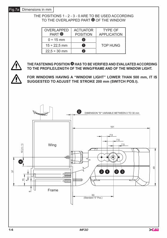
THE POSITIONS 1 - 2 - 3 - 0 ARE TO BE USED ACCORDINGTO THE OVERLAPPED PART D OF THE WINDOW
OVERLAPPEDPART D
ACTUATORPOSITION
TYPE OFAPPLICATION
0 ÷ 15 mm 0
TOP HUNG15 ÷ 22,5 mm 1
22,5 ÷ 30 mm 2
THE FASTENING POSITION A HAS TO BE VERIFIED AND EVALUATED ACCORDING TO THE PROFILE/LENGTH OF THE WING/FRAME AND OF THE WINDOW LIGHT.
FOR WINDOWS HAVING A “WINDOW LIGHT” LOWER THAN 500 mm, IT IS SUGGESTED TO ADJUST THE STROKE 200 mm (SWITCH POS.I).
Fig.7a Dimensions in mm
A
2 3 0
D DIMENSION "D" VARIABLE BETWEEN 0 TO 30 mm
10 (+
/- 1)
53
49
37
7.5
7.5
7.5
6
15 4
101
Frame
Wing
(Standard “0” Pos.)

15MF30
THE POSITIONS 1 - 2 - 3 - 0 ARE TO BE USED ACCORDINGTO THE OVERLAPPED PART D OF THE WINDOW
0 ÷ 15 mm 0 TOP HUNG(see Fig.34)7,5 ÷ 22,5 mm 3
THE DIMENSION C IS INCLUDED BETWEEN 96,6 mm AND 119,1 mm.
THE FASTENING POSITION A HAS TO BE VERIFIED AND EVALUATED AC-CORDING TO THE PROFILE/LENGTH OF THE WING/FRAME AND OF THE WINDOW LIGHT.
Fig.7b
STROKE MIN. WINDOW LIGHT OPENING ANGLE MOTOR OVERALLDIMENSIONS (B)
200mm 500mm 22° 39.5mm380mm 950mm 24.5° 41.5mm
Dimensions in mm
D
50
9
55
53
7.5
85
20.5 4
3754
3711
A
C
2 3 0
BFrame
Wing
10,5 1
E
6
DIMENSION "D" VARIABLEBETWEEN 0 TO 22,5 mm

16 MF30
5.2- TOP HUNG WINDOWS(Fig. 8 and Fig. 14 ÷ 25)
1) Open the package (par. 3.7) and extract the various com-ponents;
2) Fig.14- With a pencil draw the centre line “X” of the win-dow frame;
3) Fig.15- Align the quick coupling to the centre line using as reference the rib (Ref. 1) located in the centre of the same with the quick release side indicator on the right (Ref. 2);
4) Fig.16- Position the quick coupling at a minimum height of 10 mm from the frame and mark the drilling points;
5) Fig.17/18- With a suitable drill, perform two holes on the wing and tighten the quick coupling with proper screws;
6) Fig.19- Align to the centre line the window frame connection bracket using as reference the indicator of the centre line (Ref. 1) located in the middle of the same;
7) Position the bracket on the frame at such a height as to align the axis of the bracket fasten-ing seat with the axis of the fastening holes of the quick coupling, as indicated in Fig. 20 and mark the drilling points;
8) Fig.21-22- With a suitable drill, perform four holes on the frame and tighten the bracket with proper screws;
VERIFY THAT THE CHAIN ADJUSTMENT END (FIG. 9 - Ref. A) IS ON THE SAME AXIS OF THE QUICK COUPLING (FIG. 9 - Ref. B). OTHERWISE, REPEAT THE OPERATIONS AND POSITION CORRECTLY; WHEN THEY ARE NOT COAXIAL, THIS MAY DAMAGE THE ACTUATOR AND THE WINDOW FRAME (FIG. 9).
Fig.8
Fig.9
A AB B
NO SI

17MF30
9) Fig.23- Loosen the chain end adjustment screw (Ref. 3) and connect the actuator to the semi-automatic coupling inserting the chain adjustment end first of all in the left connection point (Ref. 1) and then in the right connection point (Ref. 2);
10) Fig.24- Using the two supplied screws (Ref. 1) tighten the actuator to the window frame con-nection bracket in the most suitable position according to the value of the overlapped part “D” (see Fig. 7a) and tighten the chain end adjustment screw (Fig. 23 - Ref. 3);
11) Fig.25- Adjust the opening stroke by means of the switch (Ref. 1) located in the right side of the actuator according to the wing opening;
TO CHANGE THE PRE-SET STROKE, USE A SCREWDRIVER (FIG. 25) WITH SUITABLE TIP. MAKE SURE TO INSERT THE TIP UP TO THE MICROSWITCH BASE AND TO SHIFT IT COMPLETELY. AN INCORRECT IN-BETWEEN POSI-TION STALLS THE ACTUATOR.
12) Perform the electric connection according to the provisions of par. 5.4 and referring to the wiring diagram.
THE SELECTION OF THE STROKE MUST BE PERFORMED WITH SWITCHED OFF ACTUATOR EXCLUSIVELY BY COMPETENT AND QUALIFIED TECHNICAL PERSONNEL.
CAUTION: VERIFY THAT THE SELECTED STROKE IS SOME CENTIMETRES LOWER THAN THE STROKE EFFECTIVELY ALLOWED BY MECHANICAL LOCKS, COMPASS LIMIT DEVICES OR WING OPENING HINDRANCES.
FOR A CORRECT ADJUSTMENT OF THE WINDOW FRAME CLOSING SEE THEINDICATIONS GIVEN IN PAR. 5.6.
5.3- BOTTOM HUNG WINDOWS (Fig. 10 and 26 ÷ 36)
1) Open the package (par. 3.7) and extract the various components;
2) Fig.26- With a pencil draw the centre line “Y” of the window frame;
3) Fig.27- Align to the centre line the window frame con-nection bracket using as reference the centre line indi-cator (Ref. 1) located in the middle of the same, then mark the drilling points on the frame;
4) Fig.28/29- With a suitable drill, perform four holes on the frame and tighten the bracket with the suitable screws;
5) Fig.30- Align the bottom hung bracket with the centre line of the window using as reference the central hole of the fastening screws and position the bottom hung bracket at E (see Fig. 7b), then mark the drilling points;
6) Fig.31/32- With a suitable drill, perform 3 holes of Ø 3.7 mm on the wing and tighten the bracket with proper screws;
Fig.10

18 MF30
7) Fig.33- Tighten with the two standard supplied screws (Ref. 1) the actuator on the bracket connecting it to the window frame in the position “0” (see Fig. 7b) and unscrew the chain adjustment end screw;
8) Fig.34- Select the position of the actuator with reference to the bracket connecting it to the window frame (see Fig. 7b) and connect the chain end to the bottom hung bracket;
9) Fig.35/36- Adjust the opening stroke by the switch (Fig. 35 - Ref. 1) located on the right side of the actuator according to the opening of the wing and tighten the chain end adjustment screw (Fig. 36 - Ref. 2);
TO CHANGE THE PRE-SET STROKE, USE A SCREWDRIVER (FIG. 35) WITH SUITABLE TIP. MAKE SURE TO INSERT THE TIP UP TO THE MICROSWITCH BASE AND TO SHIFT IT COMPLETELY. AN INCORRECT IN-BETWEEN POSI-TION STALLS THE ACTUATOR.
10) Perform the electric connections in compliance with the provisions of par. 5.4 and with refer-ence to the wiring diagram.
THE SELECTION OF THE STROKE MUST BE PERFORMED WITH SWITCHED OFF ACTUATOR EXCLUSIVELY BY COMPETENT AND QUALIFIED TECHNICAL PERSONNEL.
CAUTION: VERIFY THAT THE SELECTED STROKE IS SOME CENTIMETRES LOWER THAN THE STROKE EFFECTIVELY ALLOWED BY MECHANICAL LOCKS, COMPASS LIMIT DEVICES OR WING OPENING HINDRANCES.
FOR A CORRECT ADJUSTMENT OF THE WINDOW FRAME CLOSING SEE THE INDICATIONS GIVEN IN PAR. 5.6.

19MF30
5.4- ELECTRIC CONNECTIONS (Wiring diagram)
THE ELECTRIC CONNECTION OF THE ACTUATOR CAN BE PERFORMED ONLY BY COMPETENT AND QUALIFIED TECHNICAL PERSONNEL SATISFYING THE TECHNICAL AND PROFESSIONAL REQUIREMENTS FORESEEN BY THE LAW IN FORCE IN THE COUNTRY OF INSTALLATION ISSUING TO THE CUSTOM-ER A DECLARATION OF CONFORMITY FOR THE CONNECTION AND/OR THE PLANT PERFORMED.
BEFORE PERFORMING THE ELECTRIC CONNECTION OF THE ACTUATOR, VERIFY THE CORRECT INSTALLATION ON THE WINDOW.
THE ELECTRIC CONNECTION OF THE VERSION MF30/24V HAS TO BE CAR-RIED OUT WITH A VERY LOW SAFETY VOLTAGE FEEDER PROTECTED AGAINST SHORT CIRCUITS.
THE MAINS TO WHICH THE ACTUATOR IS CONNECTED MUST COMPLY WITH THE REQUIREMENTS OF THE LAWS IN FORCE IN THE COUNTRY OF INSTAL-LATION, AS WELL AS SATISFY THE TECHNICAL FEATURES GIVEN IN TAB. 1 AND ON THE RATING PLATE AND THE “CE” MARKING (PAR. 3.1).
THE SECTION OF THE MAINS CABLES MUST BE PROPERLY SIZED ACCORD-ING TO THE ABSORBED ELECTRIC POWER (SEE RATING PLATE AND “CE” MARKING).
ANY TYPE OF ELECTRIC MATERIAL (PLUG, CABLE, TERMINALS, ETC.) USED FOR THE CONNECTION MUST BE SUITABLE FOR THE USE, WITH “CE” MARK-ING AND COMPLYING WITH THE REQUIREMENTS FORESEEN BY THE LAWS IN FORCE IN THE COUNTRY OF INSTALLATION.
TO ASSURE A CORRECT SEPARATION FROM THE MAINS, IT IS COMPULSORY TO INSTALL UPSTREAM OF THE DEVICE A BIPOLAR TEMPORARY SWITCH (PUSHBUTTON) OF APPROVED TYPE. UPSTREAM OF THE CONTROL LINE, IT IS COMPULSORY TO INSTALL AN UNIPOLAR CUTOUT SWITCH WITH CON-TACT OPENING OF AT LEAST 3 mm.
BEFORE PERFORMING THE ELECTRIC CONNECTION OF THE ACTUATOR, VERIFY THAT THE POWER SUPPLY CABLE IS NOT DAMAGED. SHOULD IT BE DAMAGED, IT MUST BE REPLACED BY THE MANUFACTURER OR BY THE TECHNICAL ASSISTANCE SERVICE OR IN ANY CASE BY AUTHORIZED OP-ERATORS.

20 MF30
5.5- CONTROL DEVICES
THE CONTROL DEVICES USED TO DRIVE THE ACTUATOR MUST ASSURE THE SAFETY CONDITIONS FORESEEN BY THE LAWS IN FORCE IN THE COUNTRY OF USE.
According to the different type of installations, the actuators can be driven by the following con-trol devices:
1) MANUAL PUSH-BUTTON:Bipolar switch button with central OFF position, with biased-off switch;
2) CONTROL AND FEEDING UNIT:Microprocessor control units (750K330M) controlling the single actuator or more than one actuator simultaneously by means of one or more manual pushbuttons, an infrared remote control or a 433 Mhz radio control.Control unit 850CSVP: to these control units, it is possible to connect the rain sensors , the wind sensor and the brightness sensor;
WHEN USED, CONTROL UNITS MUST PROVIDE TENSION FOR A MAX. TIME OF 120 s.
5.6- ADJUSTMENT OF THE WINDOW FRAME CLOSING (Fig. 36)
THE CORRECT ADJUSTMENT OF THE WINDOW FRAME CLOSING ASSURES THE LIFE AND THE TIGHTNESS OF THE SEALS, AS WELL AS THE GOOD OP-ERATION OF THE ACTUATOR.
A good method to perform a correct assembly, consists in verifying that after the disabling of the gear motor the window seals are correctly compressed. Should this not occur, adjust again the chain end by placing it back as needed and eventually by shifting the actuator on the various positions offered by the bracket and then by adjusting the chain end (see Tab. 1).
As shown in Fig. 36, although the window is closed, the chain end adjustment screw (Ref. 2) is located outside the slit (Ref. 1) located on the actuator body causing therefore the failed tripping of the limit switch related to the chain re-entering.
IIn this case, the actuator motor remains under maximum stress conditions until the electronic protection tripping and the “BUZZER” enabling.This acoustic warning device emits a continuous “beep” until the actuator is connected to the power supply.
CONSIDERING THAT THIS ADDITIONAL SAFETY DEVICE HAS BEEN DEVEL-OPED IN ORDER TO OFFER A RAPID SYSTEM TO DETECT ANY EVENTUAL ANOMALY IN THE ASSEMBLY OF THE DEVICE, FOR A CORRECT INSTALLA-TION OF THE PRODUCT IT IS COMPULSORY TO FOLLOW ALL THE ASSEM-BLING PROCEDURES DESCRIBED IN THIS MANUAL.

21MF30
5.7- EMERGENCY PROCEDURES
Should it be necessary to open the window manually due to power supply failure or mechanism block, follow these instructions:
BEFORE PERFORMING ANY TYPE OF INTERVENTION ON THE ACTUATOR AND ON THE WINDOW, IT IS COMPULSORY TO DISCONNECT THE POWER SUPPLY OF THE ACTUATOR AND TO PUT ON “0” THE EVENTUAL SWITCHES OF THE CONTROL DEVICES.
IT IS COMPULSORY TO PADLOCK THE MAIN SWITCH OF THE DISCONNEC-TION DEVICE INSTALLED ON THE MAINS IN ORDER TO AVOID ANY UNEX-PECTED START. IF THE MAINSWITCH CANNOT BE PADLOCKED, IT IS COM-PULSORY TO PLACE A SIGN FORBIDDING THE ENABLING.
IN SOME CASES, THE EVENT OF POSSIBLE ANOMALIES MIGHT STALL ALSO OTHER ACTUATORS CONNECTED IN PARALLEL. TO FIND THE SUPPOSED MALFUNCTIONING ACTUATOR, RUN SOME CLOSING OPERATIONS IN SUC-CESSION (ABOUT 10 OPERATIONS EVERY 2 SECONDS), TILL THE WORKING ACTUATORS START RUNNING AGAIN.
• Top hung opening: Fig. 11- Insert a screw driver in the right side opening (Ref. 1) of the quick coupling and lever on the reed holding the chain end and extract the actuator.
• Bottom hung opening: Fig. 12- Act on the chain end adjustment screw (Ref.1) and let the actuator rotate upwards until the same is removed from the bottom hung opening bracket.
Fig.11 Fig.12
1
1

22 MF30
6- USE AND OPERATION
6.1- USE OF THE ACTUATOR
THE ACTUATOR CAN BE USED ONLY BY A USER ACTING IN COMPLIANCE WITH THE INSTRUCTIONS GIVEN IN THIS MANUAL AND/OR IN THE MANU-AL OF THE ACTUATOR COMMAND DEVICE (e.g.: WIND AND RAIN CONTROL UNIT).
BEFORE USING THE ACTUATOR, IT IS COMPULSORY FOR THE USER TO READ AND UNDERSTAND IN ALL ITS PARTS THIS MANUAL, AS WELL AS THE EVENTUAL MANUAL OF THE INSTALLED CONTROL DEVICE TYPE.
BEFORE OPERATING THE ACTUATOR, THE USER MUST COMPULSORILY VERIFY THAT NEAR AND/OR UNDER THE WINDOW THERE ARE NOT ANY PERSON, ANIMAL AND THING WHOSE SAFETY MAY BE ACCIDENTALLY JEOPARDISED (SEE PAR. 4.4).
DURING THE OPERATION OF THE ACTUATOR CONTROL DEVICE, THE USER HAS TO COMPULSORILY OCCUPY A CONTROL POSITION ASSURING VISUAL CONTROL ON THE WINDOW MOVEMENT.
THE FUNCTION EFFICIENCY AND THE RATED PERFORMANCE OF THE AC-TUATOR, OF THE WINDOW FRAME ON WHICH IT IS INSTALLED AND OF THE ELECTRIC EQUIPMENT MUST BE VERIFIED STEADILY IN TIME BY PERFORM-ING, WHEN NECESSARY, INTERVENTIONS OF ROUTINE AND SUPPLEMEN-TARY MAINTENANCE ASSURING THE OPERATION CONDITIONS IN COMPLI-ANCE WITH THE SAFETY REGULATIONS.
ALL ABOVE MENTIONED MAINTENANCE INTERVENTIONS MAY BE PER-FORMED EXCLUSIVELY BY TECHNICAL COMPETENT AND QUALIFIED TECH-NICAL PERSONNEL SATISFYING THE TECHNICAL AND PROFESSIONAL RE-QUIREMENTS FORESEEN BY THE LAW IN FORCE IN THE COUNTRY OF IN-STALLATION.
The use of the actuator allows to control automatically the opening and closing of the window according to the type of control device installed (see par. 5.5).

23MF30
7- MANUTENZIONE
7.1- GENERAL INSTRUCTIONS
IF THE ACTUATOR WORKS INCORRECTLY, CONTACT THE MANUFACTURER.
ANY WORK ON THE ACTUATOR (E.G.: POWER CABLE, ETC.) OR ITS COM-PONENTS MAY ONLY BE CARRIED OUT BY PERSONNEL QUALIFIED BY THE MANUFACTURER.TAU DECLINES ALL LIABILITY FOR WORK PERFORMED BY UNAUTHORISED PEOPLE.
The actuator incorporates components that do not require significant routine or extraordinary maintenance operations.In heavy-duty conditions (e.g.: very dirty work areas, frequent use, elevated temperature chang-es, load variations caused by wind or snow, etc.) make sure, at least once every 6 months, that the actuator assembly components are clean, the fixing systems (brackets and screws) are tight, the window frame is not deformed and the seals are tight, and check the cables and con-nectors.If any malfunctions arise after cleaning or inspection, contact the TAU technical assistance ser-vice.
8- DEMOLITION
8.1- GENERAL INSTRUCTIONS
THE DEMOLITION OF THE ACTUATOR MUST OCCUR IN COMPLIANCE WITH THE LAWS IN FORCE ON ENVIRONMENT PROTECTION.
DIFFERENTIATE THE PARTS MAKING UP THE ACTUATOR ACCORDING TO THEIR DIFFERENT MATERIAL TYPE (PLASTIC, ALUMINIUM, ETC.).
9- SPARE PARTS AND ACCESSORIES UPON REQUEST
9.1- GENERAL INSTRUCTIONS
THE USE OF “NON-ORIGINAL” SPARE PARTS AND ACCESSORIES WHICH MAY ENDANGER THE SAFETY AND THE EFFICIENCY OF THE ACTUATOR IS FORBIDDEN. THIS ACTION SHALL INVOLVE THE WARRANTY EXPIRATION.
ORIGINAL SPARE PARTS AND ACCESSORIES HAVE TO BE REQUESTED EX-CLUSIVELY TO YOUR DEALER OR TO THE MANUFACTURER STATING TYPE, MODEL, SERIAL NUMBER, AND YEAR OF CONSTRUCTION OF THE ACTUA-TOR.

24 MF30
Fig.13
FOR A CORRECT OPERATION OF THE ACTUATOR, “D” MUST HAVE A VAL-UE INCLUDED BETWEEN 0 mm AND 30 mm.
WING
FRAME
DOME ASSEMBLY BRACKET

25MF30
Fig.14 Fig.15
Fig.18 Fig.19
Fig.17Fig.16
X
1 2
SX
DX
H=1
0±1m
m
X X
X
1

26 MF30
Fig.20 Fig.21
Fig.24 Fig.25
Fig.23Fig.22
Wing
Frame
X
1
I= 200 mm II= 380 mm1
1
3
2
DXSX
DX

27MF30
Fig.26 Fig.27
Fig.30 Fig.31
Fig.29Fig.28
Y Y
1
H=6
,0±1
mm
H=6
,0±1
mm
E
H=1
0,5±
1mm

28 MF30
Fig.32 Fig.33
Fig.36
Fig.35Fig.34
E
H=1
0,5±
1mm
1 2
Wing
Frame
DDIMENSION "D" VARIABLEBETWEEN 0 TO 22,5 mm
3 Wing
Frame
I= 200 mm II= 380 mm
1
1 2

29MF30
CLOSES
BLACK
230V~50HzN
L
OPENS
MF30
MF30
MF30
BROWN
CLOSES
BLACK
GRAY(BLUE)
GRAY(BLUE)
230V~50HzN
L
OPENS
BROWN
Wiring diagram230 V
A
AA
A
THIS SYMBOL IDENTIFIES THE TAU ELECTRICAL ACTUATORIN WIRING DIAGRAMS.
30 MF30
GUARANTEE: GENERAL CONDITIONSTAU guarantees this product for a period of 24 months from the date of purchase (as proved by the sales document, receipt or invoice).This guarantee covers the repair or replacement at TAU’s expense (ex-works TAU: packing and transport at the customer’s expense) of parts that TAU recognises as being faulty as regards workmanship or materials.For visits to the customer’s facilities, also during the guarantee period, a “Call-out fee” will be charged for travelling expenses and labour costs.
The guarantee does not cover the following cases:• If the fault was caused by an installation that was not performed according to the instruc-
tions provided by the company inside the product pack.• If original TAU spare parts were not used to install the product.• If the damage was caused by an Act of God, tampering, overvoltage, incorrect power
supply, improper repairs, incorrect installation, or other reasons that do not depend on TAU.
• If a specialised maintenance man does not carry out routine maintenance operations according to the instructions provided by the company inside the product pack.
• Wear of components.
The repair or replacement of pieces under guarantee does not extend the guarantee period.In case of industrial, professional or similar use, this warranty is valid for 12 months.

31MF30

Via Enrico Fermi, 4336066 Sandrigo (VI) - ItalyTel +39 0444 750190Fax +39 0444 [email protected]