installation and service manual - allied...
TRANSCRIPT

PN6510930
INSTALLATION AND SERVICE MANUAL
4 kW to 54 kW, 208 Vac to 600 Vac, Single or Three Phase 180ºF instantaneous hot water for commercial dishwashers Suitable for installation with all “name-brand” dishwashers
SPACESAVER ELECTRIC BOOSTER HOT WATER HEATERS
Manufactured by
Allied Engineering Company Division of E-Z-Rect Manufacturing Ltd.
Manufacturers of Gas and Electric Boilers, Heat Exchangers, Electric Boosters, Indirect Tanks 94 Riverside Drive, North Vancouver, B.C. V7H 2M6 Telephone 604-929-1214 www.alliedboilers.com
Branches: Calgary Edmonton Toronto Denver
WARNING
RISK OF ELECTRIC SHOCK - This unit may be connected to more than one electrical circuit. Turn off all electrical supply circuits before servicing.
Failure to follow the information in this manual exactly may result in property damage, personal injury or loss of life. Read all instructions provided in this manual and all other information supplied with the booster before installing. This manual must be used by a qualified heating installer or service technician only.
IMPORTANT The booster heater must be installed in accordance with all applicable
national, provincial/state, and local codes, laws, regulations, and ordinances.
Carefully read this manual. This manual must be left with the owner and should be located adjacent to the booster for reference.
Ensure booster heater is full of water before turning on electricity. Elements will burn out immediately without water in the booster heater.
Booster heater voltage must be correct for voltage available. Check nameplate on the booster heater for full information.
Overcurrent protection between the power supply and the booster heater must be provided in accordance with the national and/or local codes.
Always ensure power switch is turned off before servicing. Under no circumstances should any electrical wiring or internal controls be
touched, except by a qualified electrician or any heating system be adjusted, except by a qualified service technician.
SAVE THESE INSTRUCTIONS.
DATE OF INSTALLATION :
INSTALLED BY :
PHONE :

Electric Booster– Installation, Operating and Maintenance Instructions
2
Dimensions, Piping Diagram and Specifications Section 1
1.1 DIMENSIONS AND PIPING DIAGRAM
Figure 1 – Dimensions and Piping Diagram
1.2 TECHNICAL SPECIFICATIONS
Maximum Operating Pressure 130 p.s.i.
Maximum Operating Water Temperature 210ºF
Water Capacity in booster – 4-18kW 4.27 US Gallons
Water Capacity in booster – 24-54kW 5.80 US Gallons
Inlet and Outlet Pipe Size 3/4” NPT

Electric Booster– Installation, Operating and Maintenance Instructions
3
TABLE 1. Super Hot Electric Booster Heater Specifications (Flange Type Elements)
BOOSTER MODEL NUMBERS, kW RATINGS AND MAX. AMPERAGE DRAW
Model
Number kW Btu/Hr
Tank
Capacity
U.S. Gal
U.S. Gal./Hr
40ºF Rise
Maximum Amperage Draw Approx.
Shipping
Weight
Single Phase Three Phase
208 240 208 240 480 600
304B 4 13,649 4.27 41 19.2 16.7 -- -- -- -- 60 LBS
305B 5 17.062 4.27 52 24.0 20.8 -- -- -- -- 60 LBS
306B 6 20,474 4.27 62 28.8 25.0 16.6 14.4 7.2 5.8 60 LBS
309B 9 30,711 4.27 93 43.3 37.5 25.0 21.6 10.8 8.7 60 LBS
312B 12 40,948 4.27 124 57.7 50.0 33.3 28.8 14.4 11.5 65 LBS
315B 15 51,185 4.27 156 72.1 62.5 46.4* 40.2* 20.1* 16.1* 65 LBS
318B 18 61,422 4.27 187 86.5 75.0 54.6* 47.3* 23.7* 18.9* 70 LBS
424B 24 81,895 5.80 249 115 100 66.5 57.7 28.8 23.1 70 LBS
430B 30 102,369 5.80 311 144 125 83.2 72.1 36.0 28.8 75 LBS
436B 36 122,843 5.80 373 173 150 100 86.5 43.3 34.6 75 LBS
545B 45 153,554 5.80 467 216 188 125 108 54.1 43.3 90 LBS
554B 54 184,264 5.80 560 260 225 150 130 64.9 51.9 90 LBS
SPECIFY MODEL NUMBER, VOLTAGE AND EITHER 1 OR 3 PHASE WHEN ORDERING
* Delta connection (unbalanced load): Leg with highest value of line current is indicated.
1.3 WATER TEMPERATURE RECOVERY
Booster Heater water recovery formulas:
G.P.H. (U.S.) = 415 x kW
L.P.H. = 874 x kW
Temp. Rise (ºF) Temp. Rise (ºC)
TABLE 2. Water Temperature Recovery in GPH (LPH)
Model kW 30ºF (17ºC) 40ºF (22ºC) 50ºF (28ºC) 60ºF (33ºC) 70ºF (39ºC) 80ºF (44ºC) 90ºF (50ºC)
304B 4 55 (208) 41 (155) 33 (125) 28 (106) 24 (91) 21 (79) 18 (68)
305B 5 69 (261) 52 (197) 41 (155) 34 (129) 29 (110) 26 (98) 23 (87)
306B 6 83 (314) 62 (235) 50 (189) 41 (155) 35 (132) 31 (117) 27 (102)
309B 9 124 (469) 93 (352) 75 (284) 62 (235) 53 (200) 47 (178) 41 (155)
312B 12 166 (628) 124 (469) 100 (379) 83 (314) 71 (269) 62 (235) 55 (208)
315B 15 208 (787) 156 (590) 125 (473) 104 (394) 89 (337) 78 (295) 69 (261)
318B 18 249 (942) 187 (708) 149 (564) 125 (473) 107 (405) 93 (352) 83 (314)
424B 24 332 (1256) 249 (942) 199 (753) 166 (628) 142 (537) 125 (473) 111 (420)
430B 30 415 (1571) 311 (1177) 249 (942) 207 (783) 178 (673) 156 (590) 138 (522)
436B 36 498 (1885) 373 (1412) 299 (1132) 249 (942) 213 (806) 187 (708) 166 (628)
545B 45 622 (2354) 467 (1767) 373 (1412) 311 (1177) 267 (1010) 233 (882) 207 (783)
554B 54 747 (2827) 560 (2120) 448 (1695) 373 (1412) 320 (1211) 280 (1060) 249 (942)

Electric Booster– Installation, Operating and Maintenance Instructions
4
Installation Instructions Section 2
2.1 RECEIVING
INSPECT SHIPMENT FOR POSSIBLE DAMAGE. All goods are carefully manufactured, inspected, checked and packed by experienced workers. The manufacturer's responsibility ceases upon delivery of goods to the carrier in good condition. Any claims for damage and/or shortage in shipment or non-delivery must be filed immediately against the carrier by the consignee.
Use care when receiving and unpacking the tank. Dropping the booster heater may cause damage and prevent safe and proper operation.
2.2 INTRODUCTION
Super Hot Electric Boosters are designed to produce 180ºF rinse water for commercial dishwashers to use in cleaning and sanitizing dishware. The high efficiency and powerful rinse output of the booster heater should result in significant savings on detergent and rinse additives. Compared with other methods of sanitizing, the Super Hot Electric Booster is the economical choice and provides exceptional quality and reliability.
2.3 INSTALLATION CODES AND REQUIREMENTS
All applicable national, provincial/state, and local codes, laws, regulations, and ordinances must be followed. They expand on and take precedence over any recommendations in this booklet. Authorities having jurisdiction shall be consulted before installations are made.
If an external electrical source is utilized, the booster heater, when installed, must be electrically grounded in accordance with local codes or, in the absence of local codes, with the National Electrical Code, ANSI/NFPA 70 (current edition) and/or the Canadian Electrical Code, CSA C22.1 Part 1 (current edition).
If there is any conflict in the above requirements, the more stringent requirement applies.
The installation and service must also conform to the additional requirements in this manual. If there is any conflict with a requirement in this manual and a code requirement, the code requirement must be followed.
Electric Booster– Installation, Operating and Maintenance Instructions
5
2.4 BOOSTER HEATER LOCATION
DANGER – RISK OF EXPLOSION
Do not use or store gasoline or other flammable fuels or chemicals which have flammable vapors near the booster. The vapors may be ignited by the heat or electronic components of the booster.
WARNING
The booster must be located in an area where water leakage of the booster or its connections will not result in damage to the area adjacent to the appliance or to the lower floors of the structure. When such locations cannot be avoided, a suitable drain pan must be installed under the appliance and the drain pan must be connected to a drain of adequate capacity.
Failure to comply with the above could result in severe personal injury, death or substantial property damage.
CAUTION
This booster must be installed such that any electronic components are protected from water (dripping, spraying, rain, etc.) during appliance operation and service.
The space saving, compact booster heater can be installed almost anywhere. The booster heater may be installed in an enclosed space and attached directly to a combustible surface, however, allow ample space for connecting, disconnecting and servicing the unit. Locate booster heater as close to dishwasher as possible. Dimensions are shown in Figure 1.
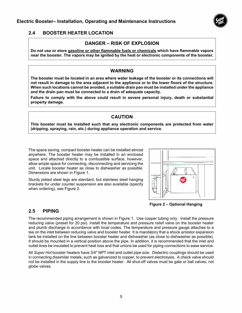
Sturdy plated steel legs are standard, but stainless steel hanging brackets for under counter suspension are also available (specify when ordering), see Figure 2.
2.5 PIPING
The recommended piping arrangement is shown in Figure 1. Use copper tubing only. Install the pressure reducing valve (preset for 20 psi). Install the temperature and pressure relief valve on the booster heater and plumb discharge in accordance with local codes. The temperature and pressure gauge attaches to a tee on the inlet between reducing valve and booster heater. It is mandatory that a shock arrestor expansion tank be installed on the line between booster heater and dishwasher (as close to dishwasher as possible). It should be mounted in a vertical position above the pipe. In addition, it is recommended that the inlet and outlet lines be insulated to prevent heat loss and that unions be used for piping connections to ease service.
All Super Hot booster heaters have 3/4" NPT inlet and outlet pipe size. Dielectric couplings should be used in connecting dissimilar metals, such as galvanized to copper, to prevent electrolysis. A check valve should not be installed in the supply line to the booster heater. All shut-off valves must be gate or ball valves, not globe valves.
Figure 2 – Optional Hanging

Electric Booster– Installation, Operating and Maintenance Instructions
6
2.6 T&P RELIEF VALVE PIPING
DANGER – RISK OF EXPLOSION
A T&P (temperature and pressure) relief valve must be installed to protect against excessive temperature and pressure. Do not plug T&P relief valve or discharge piping. Plugging T&P relief valve or discharge piping can cause excessive pressure, resulting in severe personal injury, death or substantial property damage.
WARNING
The T&P valve may discharge pressurized hot water and/or steam. Steam exiting the discharge outlet can explosively expand in any direction. Always maintain a safe distance from the discharge pipe outlet in order to avoid potential contact with exiting hot water or steam.
Temperature and pressure settings of the T&P relief valve are factory set and are not adjustable. The T&P valve must be of sized capacity to handle the maximum power of booster heater and not greater than the operating restrictions stated on the rating plate of the booster heater and in this manual. Furthermore, the service pressure should be at least 25 psi less than the setting stamped on the T&P relief valve.
Install the T&P relief valve directly into the T&P valve connection provided on the booster heater so that the temperature sensing element is immersed in the water. No valve, reducing coupling or other restriction is to be placed between the T&P relief valve and the booster heater connection. No valve, reducing coupling, pipe plug, pipe cap or other restriction is to be placed in the discharge piping. Improper placement or piping of the T&P relief valve can cause severe personal injury, death or substantial property damage.
The discharge line shall be installed to allow the complete drainage of both the valve and the line. It shall be independently supported or arranged so as to avoid undue stress on the valve. Do not pipe in any area where freezing may occur.
The termination of the T&P relief valve discharge line shall be downward and not directly connected to a sewer line. The outlet of the discharge line shall terminate in the vicinity of a point of drainage within 6” of the floor to eliminate potential risk of scalding and should terminate freely to atmosphere where any discharge will be clearly visible and is at no risk of freezing.
2.7 WATER HAMMER
Water hammer is a damaging pressure shock wave created when the flow of water is suddenly stopped or reduced (possibly induced by fast-closing faucet, reducing valve, or solenoid valve in a clothes/dishwashing machine). This condition is commonly associated with hammering noises and vibrations; however, lack of noise does not assure that water hammer is not present. Risers or air chambers do not provide protection. To prevent damage to piping and the water heater: (1) install properly-sized water hammer arrestors at all required locations and (2) adequately size pipes to ensure a maximum water velocity less than 5 ft/s.
2.8 FUNCTION OF PIPING ACCESSORIES
Shock Arrestor Expansion Tank:
Quick closing solenoid valves on the dishwasher will produce a shock pressure exceedingly high – up to 800 lbs. This may cause leaks in the plumbing and damage equipment such as relief valves, gauges, tank, etc. The Shock Arrestor Expansion Tank provided with the booster heater must be installed.
Temperature and Pressure Indicating Gauge:
This gauge indicates the temperature and pressure and is useful when determining incoming water temperature or adjusting the pressure reducing valve. It should be installed between the pressure reducing valve and booster heater.
When a dishwasher is not equipped with a temperature gauge, a second gauge should be installed as close to dishwasher as possible to verify 180ºF rinse temperature.

Electric Booster– Installation, Operating and Maintenance Instructions
7
Temperature and Pressure Relief Valve:
The relief valve protects the tank from becoming overheated and/or over-pressurized. It opens and releases water if the temperature exceeds 210ºF or if the pressure exceeds 125 psi (satisfies most local codes). This device must be installed directly on the booster heater.
Pressure Reducing Valve with By-Pass:
When the supply pressure exceeds the final rinse pressure requirements, a pressure reducing valve with built-in by-pass should be installed in the supply line to the booster heater. A pressure reducing valve without a by-pass should not be installed as water expansion due to heating will cause the relief valve to open.
Optional Extra Low Water Cut-Off:
A number of service calls are caused by energizing the heating elements in a “dry” tank. Even momentary testing of the installation when the tank is dry will appreciably shorten the life of the element or burn it out and affect the calibration of the aquastat.
The low water cut-off will protect the heating elements from damage by sensing if the tank is completely filled with water before allowing the elements to operate.
2.9 WATER QUALITY
Always use good quality water to prolong the life of the booster. Water that is safe to drink and even city water is not necessarily good quality water for the booster. The use of water treatment and filters can prevent corrosion and reduce sediment in the booster. Water hardness, pH, and chlorides must be controlled to normal levels.
PH levels must be between 6.0 and 8.0
Chlorine, chlorides or aggressive sulfates concentrations must be below 100 parts per million.
If you are unsure, use a water softening system or consult a qualified water treatment expert.
NOTE: All improper use as detailed above could void the warranty of the booster.
Wiring and Controls Instructions Section 3
3.1 WIRING
WARNING
Turn off all the electric power before any wiring or service. All circuit breakers ahead of or related to the booster operation must be switched off.
All electrical wiring is to be done in accordance with the Canadian Electrical Code, CSA C22.2 part 1, and/or any local regulations and codes in Canada, or the National Electrical Code, ANSI/NFPA 70 (latest edition) and/or any local regulations and codes in U.S.A. Verify the nameplate rating and check the related codes to properly size conductors, switches and over-current protection. Check the voltage at the feeder panel, compare to the values shown in Table 1, and supply the correct voltage power to the power supply block on the booster heater. For wire connections, refer to the wiring diagram sticker on the back of the booster heater front cover.
CAUTION
AC ONLY, USE COPPER WIRE ONLY. DO NOT USE ALUMINUM.

Electric Booster– Installation, Operating and Maintenance Instructions
8
3.2 CONTROLS
A “rapid response” aquastat provides temperature control and ensures safe operation. The aquastat switch incorporates a magnetic contactor to complete the power circuit to the heating elements and control the water temperature. By use of an adjustable dial the operating aquastat can control the water to the desired temperature.
The electrical controls come pre-wired on the right-hand side of each booster heater where it is protected from high ambient temperatures.
An indicator light visible on the front panel indicates that there is power to the heating elements when the booster heater is in operation.
The low water cut-off (optional) uses a resistance-sensing probe to determine if the booster heater is filled with water. If the booster heater is filled with water, the relay coil will close and allow the element to turn on. Sensing resistance is dial-adjustable, turn dial clockwise to increase sensitivity.
Start-up Instructions Section 4
4.1 START-UP
WARNING
The following instructions are intended as a guide for qualified persons.
Before filling the booster, make sure that the T&P relief valve is installed and that the unit is properly grounded.
Before switching power on, fill system with water and vent air. Check for and repair any leaks in water piping.
Perform the following procedure to check for proper booster heater operation:
1. Ensure power to the booster heater is turned OFF.
2. Set operating aquastat to give desired water temperature for dishwasher (usually 180ºF).
3. The operating aquastat setting should be at least 20ºF less than the temperature setting of T&P relief valve (210ºF).
4. Run water through the booster heater for 5 minutes (or longer, if necessary) to ensure it is purged of air and completely filled with water.
5. Check flow pressure with water flowing through the booster heater and, if necessary, readjust the pressure reducing valve to 20 psi or to pressure recommended by dishwasher manufacturer.
6. Switch power to the booster heater ON.
7. The pilot lamp indicates that power is on when booster heater is operating.
8. Run a test cycle of dishwashing to confirm proper operation.
Maintenance Instructions Section 5
5.1 IMPORTANT
Many times when a booster heater does not appear to be functioning properly, the fault lies not with the booster heater itself but with factors outside of the heater. Therefore, before becoming involved in corrective work on the booster heater, the following steps should be followed:
Check the temperature of the water feeding into the booster heater tank. It must be 140ºF or the temperature designed and must be in sufficient quantity to hold its temperature throughout the dishwashing operation.
Incoming water temperature to the booster heater should not exceed 170ºF.
If incoming water exceeds 20 psi, a pressure reducing valve must be installed.

Electric Booster– Installation, Operating and Maintenance Instructions
9
If the wash tank of the dishwasher is filled through the booster heater, this will use up all the 180ºF water in storage. Sufficient time must be allowed to reheat the water in storage before starting the dishwasher.
Water pressure at the inlet to the booster heater must be adequate for proper operation of the rinse cycle of the dishwasher.
Be sure that the relief valve is one supplied by Allied Engineering Company.
A check valve should not be installed ahead of the booster heater. Remove if present.
REPLACEMENT PARTS Section 6
6.1 ORDERING
Replacement parts or a replacement booster heater may be purchased through any Allied Engineering Company distributor – call us if you need help locating a distributor near your area. If you require any technical assistance or have any comments about our product, please write or phone us at:
Service Department Allied Engineering Company 94 Riverside Drive North Vancouver, B.C. CANADA V7H 2M6 Tel (604) 929-1214 Fax (604) 929-5184 Email: [email protected]
NOTE: To supply the correct part it is important that you state the model number and serial number.
Figure 3 – Replacement Parts

Electric Booster– Installation, Operating and Maintenance Instructions
10
Troubleshooting Section 7
7.1 TROUBLESHOOTING
Problem Possible Cause Solution
Temperature too low or too high. (Read rinse thermometer on dishwasher)
Incorrect thermostat setting Remove booster heater front panel.
Adjust thermostat to correct setting and check thermometer during rinse cycle.
If machine cold, run rinse cycle twice before checking proper reading. Temperature should reach 180ºF – 185ºF (82ºC –85ºC).
Thermostat defective Check and replace, if necessary.
Rinse water temperature still too low during continuous use.
Water supply to booster heater below 140ºF (60ºC).
Read incoming water temperature by combination gauge. Incoming temperature should be 140ºF (60ºC) (unless booster heater is specifically designed for lower supply temperature).
Increase incoming water temperature to 140ºF (60ºC) at hot water supply tank.
Pressure setting of pressure reducing valve too high.
Read pressure on combination gauge during rinse cycle.
Pressure reducing valve “PRV” should be adjusted to dishwasher specifications usually between 20 – 25 p.s.i.
Thermometer on dishwasher not functioning properly.
Tap thermometer gauge with finger during rinse cycle. If needle does not move freely, contact dishwasher manufacturer.
Booster heater too far from dishwasher (more than 3 ft.)
Insulate pipe from booster heater to dishwasher.
Relocate booster heater closer to dishwasher.
Heating element(s) burned out, faulty contactor or loose wires
Turn off electricity to the booster heater. Check elements, contactor and wiring for continuity.

Electric Booster– Installation, Operating and Maintenance Instructions
11
Problem Possible Cause Solution
Temperature & pressure relief valve discharges water
Thermostat set too high above 185ºF (85ºC)
Remove front cover. Adjust thermostat to a lower setting.
Pressure increases to 125 p.s.i. during booster heater heating cycle because:
A. Pressure reducing valve is an incorrect style (without relief by-pass). Letter “B” should be in model number.
Replace with correct pressure reducing valve.
B. By-pass in pressure reducing valve plugged or inoperative.
While unit in heating cycle, tap pressure-reducing valve with wood hammer or screwdriver handle. If pressure gauge does not show drop in pressure, replace pressure-reducing valve.
Temperature & pressure relief valve discharges water (after checking above).
Relief valve not reseating properly.
Quickly lift and release manual discharge lever on relief valve to assist proper reseating. If this fails, replace temperature and pressure relief valve.
Water leaking from booster heater.
Element and thermostat threads may be leaking.
Turn off electricity to booster heater and tighten elements.
Turn off water, drain, remove and apply sealant if necessary. (Be sure to turn off electricity before draining or elements will burn out).
Plumbing connections may be leaking.
Tighten incoming pipes, heating elements, and temperature & pressure relief valve. Turn off water, drain and remove and apply sealant if necessary. (Be sure to turn off electricity before draining or elements will burn out).

Electric Booster– Installation, Operating and Maintenance Instructions
12
Index Section 8
Section Page
1 Dimensions, Piping Diagram and Specifications ....................................................................... 2
1.1 Dimensions and Piping Diagram ...................................................................................................... 2
1.2 Technical Specifications................................................................................................................... 2
1.3 Water Temperature Recovery .......................................................................................................... 3
2 Installation Instructions................................................................................................................. 4
2.1 Receiving ......................................................................................................................................... 4
2.2 Introduction ...................................................................................................................................... 4
2.3 Installation Codes and Requirements .............................................................................................. 4
2.4 Booster Heater Location .................................................................................................................. 5
2.5 Piping ............................................................................................................................................... 5
2.6 T&P Relief Valve Piping ................................................................................................................... 6
2.7 Water Hammer ................................................................................................................................. 6
2.8 Function of Piping Accessories ........................................................................................................ 6
2.9 Water Quality ................................................................................................................................... 7
3 Wiring and Controls Instructions ................................................................................................. 7
3.1 Wiring ............................................................................................................................................... 7
3.2 Controls ............................................................................................................................................ 8
4 Start-up Instructions ...................................................................................................................... 8
4.1 Start-up............................................................................................................................................. 8
5 Maintenance Instructions .............................................................................................................. 8
5.1 Important .......................................................................................................................................... 8
6 Replacement Parts ......................................................................................................................... 9
6.1 Ordering ........................................................................................................................................... 9
7 Troubleshooting ........................................................................................................................... 10
7.1 Troubleshooting ............................................................................................................................. 10
8 Index .............................................................................................................................................. 12