installation and reference guide - hewlett...
TRANSCRIPT

HP AdvanceStack 10Base-T Hub-8U
Installation and Reference Guide

© Copyright Hewlett-Packard Company 1997. All Rights Reserved.
Reproduction, adaptation, or translation without priorwritten permission is prohibited, except as allowed underthe copyright laws.
Publication Number
J2610-90201Edition 1July 1997
Applicable Product
HP J2610B
Trademark Credits
MS-DOS® and Microsoft® are U.S. registered trademarksof Microsoft Corporation. Ethernet is a registered trade-mark of Xerox Corporation.
Disclaimer
The information contained in this document is subject tochange without notice.
HEWLETT-PACKARD COMPANY MAKES NO WARRANTYOF ANY KIND WITH REGARD TO THIS MATERIAL,INCLUDING, BUT NOT LIMITED TO, THE IMPLIEDWARRANTIES OF MERCHANTABILITY AND FITNESSFOR A PARTICULAR PURPOSE. Hewlett-Packard shallnot be liable for errors contained herein or for incidentalor consequential damages in connection with the furnishing,performance, or use of this material.
Hewlett-Packard assumes no responsibility for the use orreliability of its software on equipment that is not furnishedby Hewlett-Packard.
Warranty
See the warranty booklet included with the product.
A copy of the specific warranty terms applicable to yourHewlett-Packard product and replacement parts can be ob-tained from your HP Sales and Service Office or authorizeddealer.
8000 Foothills Boulevard MS 5551Roseville, California 95747-5551http://www.hp.com/go/network_city
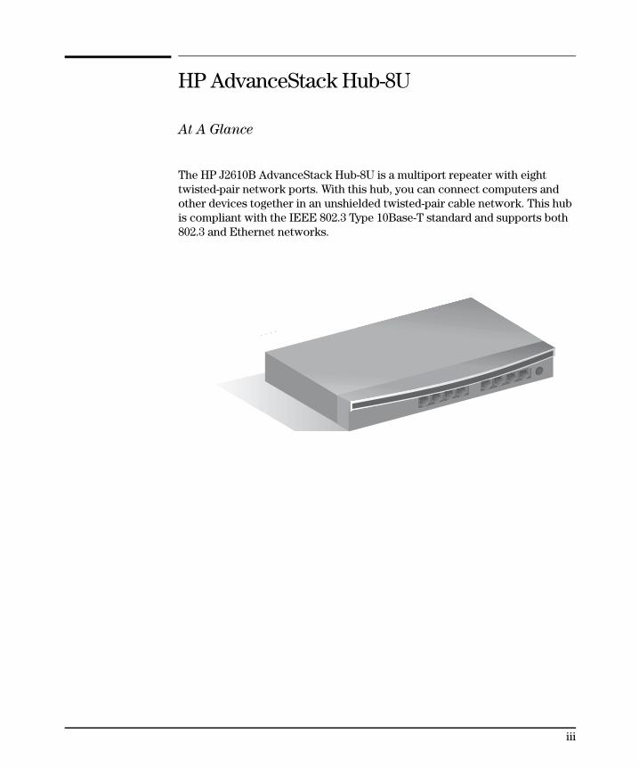
HP AdvanceStack Hub-8U
At A Glance
The HP J2610B AdvanceStack Hub-8U is a multiport repeater with eighttwisted-pair network ports. With this hub, you can connect computers andother devices together in an unshielded twisted-pair cable network. This hubis compliant with the IEEE 802.3 Type 10Base-T standard and supports both802.3 and Ethernet networks.
iii
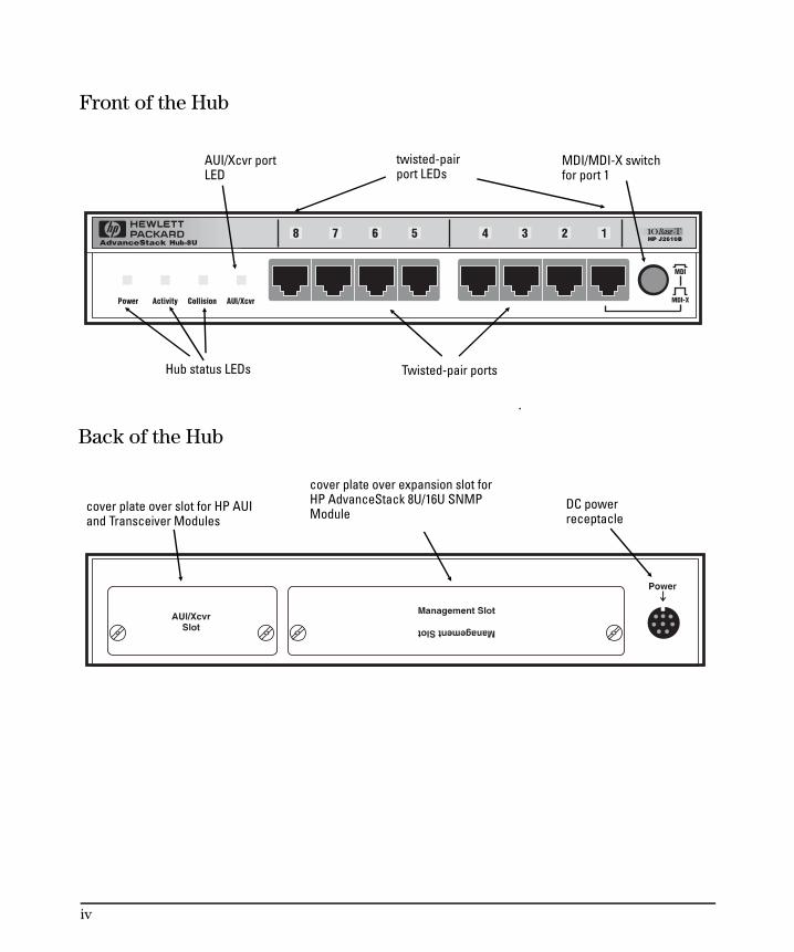
MDI/MDI-X switchfor port 1
Hub status LEDs Twisted-pair ports
twisted-pairport LEDs
AUI/Xcvr portLED
Front of the Hub
DC powerreceptacle
cover plate over expansion slot forHP AdvanceStack 8U/16U SNMPModulecover plate over slot for HP AUI
and Transceiver Modules
Back of the Hub
iv
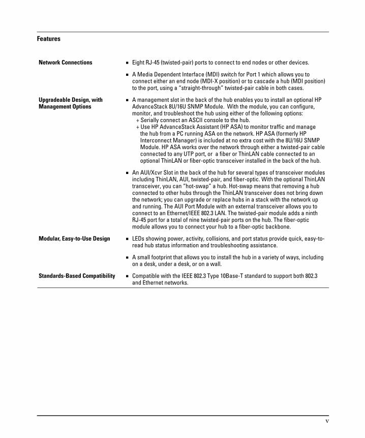
Features
Network Connections Eight RJ-45 (twisted-pair) ports to connect to end nodes or other devices.
A Media Dependent Interface (MDI) switch for Port 1 which allows you toconnect either an end node (MDI-X position) or to cascade a hub (MDI position)to the port, using a “straight-through” twisted-pair cable in both cases.
Upgradeable Design, withManagement Options
A management slot in the back of the hub enables you to install an optional HPAdvanceStack 8U/16U SNMP Module. With the module, you can configure,monitor, and troubleshoot the hub using either of the following options: + Serially connect an ASCII console to the hub. + Use HP AdvanceStack Assistant (HP ASA) to monitor traffic and manage the hub from a PC running ASA on the network. HP ASA (formerly HP Interconnect Manager) is included at no extra cost with the 8U/16U SNMP Module. HP ASA works over the network through either a twisted-pair cable connected to any UTP port, or a fiber or ThinLAN cable connected to an optional ThinLAN or fiber-optic transceiver installed in the back of the hub.
An AUI/Xcvr Slot in the back of the hub for several types of transceiver modulesincluding ThinLAN, AUI, twisted-pair, and fiber-optic. With the optional ThinLANtransceiver, you can “hot-swap” a hub. Hot-swap means that removing a hubconnected to other hubs through the ThinLAN transceiver does not bring downthe network; you can upgrade or replace hubs in a stack with the network upand running. The AUI Port Module with an external transceiver allows you toconnect to an Ethernet/IEEE 802.3 LAN. The twisted-pair module adds a ninthRJ-45 port for a total of nine twisted-pair ports on the hub. The fiber-opticmodule allows you to connect your hub to a fiber-optic backbone.
Modular, Easy-to-Use Design LEDs showing power, activity, collisions, and port status provide quick, easy-to-read hub status information and troubleshooting assistance.
A small footprint that allows you to install the hub in a variety of ways, includingon a desk, under a desk, or on a wall.
Standards-Based Compatibility Compatible with the IEEE 802.3 Type 10Base-T standard to support both 802.3and Ethernet networks.
v

Perforate
Perfo
rate
✂ Perforate
(over for more services)
HP Customer Support Services
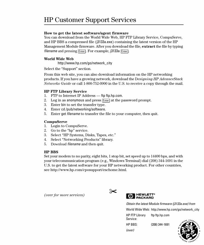
How to get the latest software/agent firmware
You can download from the World Wide Web, HP FTP Library Service, CompuServe, and HP BBS a compressed file (j3133a.exe) containing the latest version of the HP Management Module firmware. After you download the file, extract the file by typing filename and pressing [Enter]. For example, j3133a [Enter].
World Wide Web
http://www.hp.com/go/network_city
Select the “Support” section.
From this web site, you can also download information on the HP networking products. If you have a growing network, download the Designing HP AdvanceStack
Networks Guide or call 1-800-752-0900 in the U.S. to receive a copy through the mail.
HP FTP Library Service
1. FTP to Internet IP Address — ftp ftp.hp.com.2. Log in as anonymous and press [Enter] at the password prompt. 3. Enter bin to set the transfer type. 4. Enter cd /pub/networking/software.5. Enter get filename to transfer the file to your computer, then quit.
CompuServe
1. Login to CompuServe.2. Go to the “hp” service.3. Select “HP Systems, Disks, Tapes, etc.”4. Select “Networking Products” library.5. Download filename and then quit.
HP BBS
Set your modem to no parity, eight bits, 1 stop bit, set speed up to 14400 bps, and with your telecommunication program (e.g., Windows Terminal) dial (208) 344-1691 in the U.S. to get the latest software for your HP networking product. For other countries, see http://www.hp.com/cposupport/eschome.html.
Obtain the latest Module firmware (j3133a.exe) from
World Wide Web: http://www.hp.com/go/network_city
HP FTP Library Service:
ftp ftp.hp.com
HP BBS: (208) 344-1691
(over)
0_hperf%.fm5 Page 3 Tuesday, July 22, 1997 4:54 PM

Perfo
rate
Perforate
Perforate
✂
HP FIRST Fax Retrieval Service
HP FIRST is an automated fax retrieval service that is available 24 hours a day, seven days a week. HP FIRST provides information on the following topics:■ Product information■ Troubleshooting instructions■ Technical reviews and articles■ Configuration information
To access HP FIRST, dial one of the following phone numbers:
Additional HP Support Services
In addition to the above services, you can purchase various HP telephone support services which provide you expert HP technical assistance:■ Network Phone-In Support provides you support at an hourly rate. In the U.S.,
call 1-800-790-5544. In other countries, please contact your local HP Response Center to see if this service is available in your country.
■ HP SupportPack LAN Support provides problem resolution for small to medium local area networks. Contact your HP Authorized Reseller or the nearest HP Sales and Support Office for more information.
■ HP SupportPack Comprehensive Network Support provides complete prob-lem resolution for medium to large interconnected local and wide area networks. Contact your HP Authorized Reseller or the nearest HP Sales and Support Office for more information.
HP offers other hardware support services. Please contact your reseller for more information.
Location Phone Number
U.S. and Canada Only Dial 1 (800) 333-1917 with your fax machine or touch-tone phone and press 1.
Outside the U.S. and Canada Dial 1 (208) 344-4809 from your fax machine and press 9.
To receive a list of currently available documents, enter document number 19941. The information you requested will be sent to you by return fax. For other countries, see http://www.hp.com/cposupport/eschome.html.
CompuServe: Go hpsys Lib 7.Download j3133a.exe
Network Phone-In Support (hourly):
1-800-790-5544
0_hperf%.fm5 Page 4 Tuesday, July 22, 1997 4:54 PM

Table of Contents
1 Installing the Hub
Installation Summary . . . . . . . . . . . . . . . . . . . . . . . . . . . 1-2
Included Parts . . . . . . . . . . . . . . . . . . . . . . . . . . . . . . . 1-2
1. Install add-in modules (optional) . . . . . . . . . . . . . . . . . 1-3
2. Verify the hub’s operation . . . . . . . . . . . . . . . . . . . . . 1-5
3. Mount the hub . . . . . . . . . . . . . . . . . . . . . . . . . . . . 1-6Equipment Required . . . . . . . . . . . . . . . . . . . . . . . 1-6Mounting Precautions . . . . . . . . . . . . . . . . . . . . . . 1-7Marking the Location . . . . . . . . . . . . . . . . . . . . . . . 1-7Mounting the Hub . . . . . . . . . . . . . . . . . . . . . . . . . 1-8
4. Complete the network connections to the hub . . . . . . . . . 1-9Connecting Devices to the Hub . . . . . . . . . . . . . . . . . 1-9Connecting Hubs Together . . . . . . . . . . . . . . . . . . . . 1-10Twisted-Pair Cascade Connections . . . . . . . . . . . . . . . 1-10ThinLAN Connections . . . . . . . . . . . . . . . . . . . . . . 1-11Connecting Hubs to Network Backbones . . . . . . . . . . . 1-12Connecting the Hub 8U to a ThinLAN Backbone . . . . . . . 1-12Connecting the Hub 8U to a Fiber-Optic Backbone . . . . . . 1-13
5. Connect the hub to an ASCII console (optional) . . . . . . . . 1-14
2 Troubleshooting
Troubleshooting Approaches . . . . . . . . . . . . . . . . . . . . . . 2-2
Diagnosing with the LEDs . . . . . . . . . . . . . . . . . . . . . . . . 2-3LED Pattern During Self-Test . . . . . . . . . . . . . . . . . . 2-3LED Error Indications . . . . . . . . . . . . . . . . . . . . . . 2-4
Installation Problems . . . . . . . . . . . . . . . . . . . . . . . . . . . 2-6Incorrect Hardware Installation . . . . . . . . . . . . . . . . . 2-6Cabling Problems . . . . . . . . . . . . . . . . . . . . . . . . . 2-6
Connections . . . . . . . . . . . . . . . . . . . . . . . . . . . . . . . . 2-6Non-standard Cables . . . . . . . . . . . . . . . . . . . . . . . . . . . 2-7Topology . . . . . . . . . . . . . . . . . . . . . . . . . . . . . . . . . . 2-7
Unusual Network Activity . . . . . . . . . . . . . . . . . . . . . . . . 2-7
Diagnostic Tests . . . . . . . . . . . . . . . . . . . . . . . . . . . . . . 2-8Testing the Hub Only . . . . . . . . . . . . . . . . . . . . . . . 2-8Testing Twisted-Pair Cabling . . . . . . . . . . . . . . . . . . . 2-8
vii

Testing End-to-End Network Communications . . . . . . . . 2-9
Replacement Instructions . . . . . . . . . . . . . . . . . . . . . . . . 2-10
Customer Support Services . . . . . . . . . . . . . . . . . . . . . . . 2-11
3 Hub Reference
Front of the Hub . . . . . . . . . . . . . . . . . . . . . . . . . . . . . 3-2Hub status LEDs . . . . . . . . . . . . . . . . . . . . . . . . . 3-2Port status LEDs . . . . . . . . . . . . . . . . . . . . . . . . . 3-3
Back of the hub . . . . . . . . . . . . . . . . . . . . . . . . . . . . . . 3-4Management Slot . . . . . . . . . . . . . . . . . . . . . . . . . 3-4AUI/Xcvr Slot . . . . . . . . . . . . . . . . . . . . . . . . . . . 3-4
Hub Operation . . . . . . . . . . . . . . . . . . . . . . . . . . . . . . . 3-5Collision Detection . . . . . . . . . . . . . . . . . . . . . . . . 3-5Auto-Partitioning . . . . . . . . . . . . . . . . . . . . . . . . . 3-5Link Beat . . . . . . . . . . . . . . . . . . . . . . . . . . . . . . 3-6
A Cables and Connectors
Recommended Cables . . . . . . . . . . . . . . . . . . . . . . . . . . A-2
Twisted-Pair Cable/Connector Pin-Outs . . . . . . . . . . . . . . . . A-3
Twisted-Pair Cable for Hub-to-Computer Network Connection . A-3
Twisted-Pair Cable Pin Assignments . . . . . . . . . . . . . . . . . A-4Twisted-Pair Straight-Through Cable . . . . . . . . . . . . . . A-4
ThinLAN Cable Requirements . . . . . . . . . . . . . . . . . . . . . . A-4
B Specifications
Safety and Regulatory Statements
Index
viii
1
Installing the Hub
Installation Summary
1. Install Add-in Modules (optional)
2. Verify the Hub’s Operation
3. Mount the Hub
4. Complete the Network Connections to the Hub
5. Connect the Hub to an ASCII Console (optional)
This chapter describes how to install the HP AdvanceStack Hub-8U, verifyits operation, and connect it to a network, other hubs, computers, and/orother devices.
Installation Summary
The basic hardware installation procedure for the HP AdvanceStack Hub-8Uis as follows:1. Install the optional HP AdvanceStack 8U/16U SNMP Module and/or
one of the optional HP Transceiver Modules.2. Verify the hub’s operation.3. Mount the hub on a wall or under a tabletop.4. Connect the hub to a network or other hubs, and connect
computer(s) and/or other device(s) to the hub’s ports.5. (Optional) Connect the hub to the AdvanceStack 8U/16U SNMP
management console.
Included Parts
Each HP AdvanceStack Hub-8U has the following components shipped withit:
HP AdvanceStack Hub-8U Installation and Reference Guide—thismanual (J2610-90101)
An ac power cord, one of the following:Australia/New ZealandDenmarkEurope JapanSwitzerlandUnited Kingdom/Hong KongU.S./Canada
(8120-1369)(8120-2956)(8120-1689)(8120-4753)(8120-2104)(8120-1351)(8120-1378)
A power supply, part number 0950-3058
Insta
llin
g t
he H
ub
Installing the Hub
1-2

1. Install add-in modules (optional)
The HP AdvanceStack Hub-8U can be custom-configured by installing theoptional HP AdvanceStack 8U/16U SNMP Module and/or an HP TransceiverModule. If you intend to install any of these optional modules, refer to thedocumentation that was shipped with it.
It may be more convenient to install these optional modules before installingthe hub under a desk or other location. Inspect your installation site andidentify whether the hub’s module slots will be accessible.
The HP J3133A AdvanceStack 8U/16U SNMP Module enables you to connecta PC to the hub to configure, monitor, and troubleshoot the hub.
C a u t i o n To avoid possible damage to module or transceiver circuitry,
disconnect the power cable from the hub before installing (or
removing) the optional SNMP Module or a transceiver.
Installin
g th
e H
ub
Installing the Hub
1-3
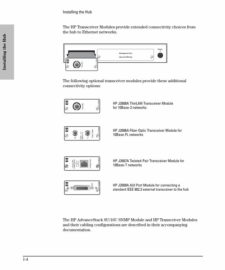
The HP Transceiver Modules provide extended connectivity choices fromthe hub to Ethernet networks.
The following optional transceiver modules provide these additionalconnectivity options:
The HP AdvanceStack 8U/16U SNMP Module and HP Transceiver Modules and their cabling configurations are described in their accompanyingdocumentation.
HP J2608A ThinLAN Transceiver Modulefor 10Base-2 networks
HP J2606A Fiber-Optic Transceiver Module for 10Base-FL networks
HP J2607A Twisted-Pair Transceiver Module for10Base-T networks
HP J2609A AUI Port Module for connecting astandard IEEE 802.3 external transceiver to the hub
Insta
llin
g t
he H
ub
Installing the Hub
1-4
2. Verify the hub’s operation
Your hub uses power from an ac adapter.
N o t e If your installation requires a different power cord than the one suppliedwith the hub, contact your HP-authorized LAN dealer or your local HPsales office.
The hub does not have a power switch; it is powered on when the powercord is plugged in.
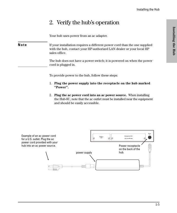
To provide power to the hub, follow these steps:
1. Plug the power supply into the receptacle on the hub marked
“Power”.
2. Plug the ac power cord into an ac power source. When installingthe Hub-8U, note that the ac outlet must be installed near the equipmentand should be easily accessible.
Power receptacleon the back of thehub.
Example of an ac power cordfor a U.S. outlet. Plug the acpower cord provided with yourhub into an ac power source.
power supply
Installin
g th
e H
ub
Installing the Hub
1-5

3. Check the LEDs on the hub’s front panel.
When the hub is powered on, it performs a self-diagnostic test.During the test, all LEDs are lit for a short time.
When the self-test completes successfully, the following events occur:
• the Power LED stays on
• the twisted-pair Port LEDs enter their normal operating state
• If an HP Transceiver module is installed, the AUI/Xcvr LED stays lit
A Port LED stays on if link beat has been detected at the port. A PortLED turns off if link beat is not detected. If you have an optional HPAdvanceStack 8U/16U SNMP Module installed, the Port LEDs haveadditional meanings. See the documentation accompanying themodule for more information. If all of the Port LEDs stay on and youhave not connected end nodes to these ports, the hub has failed itsself-test. See chapter 2, “Troubleshooting” for information aboutdiagnosing your hub.
4. After the hub has passed its self-test, you are ready to mount
the hub. Before mounting the hub, unplug it.
3. Mount the hub
The HP AdvanceStack Hub-8U can be placed on a desk or mounted on anyvertical or horizontal surface, for example, a wall or under a desk.
To locate the hub on a table or other horizontal surface, no special tools arenecessary. Be certain to pick a sturdy table in an uncluttered area. You maywant to secure the hub’s cables to the leg of the table to prevent people fromtripping over them.
Equipment Required
To mount the hub on a wall or under a desk, you will need the followingequipment:
two number 6 by half-inch or M3 x 12 mm pan head wood screws(not included with the hub)a Phillips (cross-head) screwdriver (not included with the hub)
Insta
llin
g t
he H
ub
Installing the Hub
1-6
Mounting Precautions
Before mounting the hub, follow these mounting precautions:Plan the hub’s location and orientation relative to other devices andequipment. Also consider the cabling that will be attached to the huband ports that will be used. In the front of the hub, leave 3 inches (76 mm) of space for twisted-pair cables. In the back of the hub,leave 3 inches (7 cm) of space for the ac power cord, the AdvanceStack 8U/16U SNMP module, and a serial connector.
Ensure that the HP AdvanceStack hub(s) do not overload the power
circuits, wiring, and over-current protection. To determine thepossibility of overloading the supply circuits, add together theampere ratings from the nameplates of all your hubs (and otherequipment) installed on the same circuits and compare the total withthe rating limits for the supply circuits.
Do not install the HP AdvanceStack hub in an environment wherethe operating ambient temperature might exceed 55°C (131°F).
Make sure the air flow around the sides of the hub is not restricted.
Marking the Location
I m p o r t a n t A hub should be mounted only to a wall or wood surface that is
at least 1/2-inch (12.7 mm) plywood or its equivalent.
1. Using the illustration on the next page, mark the screw hole locationson the mounting surface 4 13/16 inches (122.2 mm) apart. Make sureyou allow enough room to make the cable connections to the huband to be able to access the cables if they have to be moved.
2. Using a Phillips (cross-head) screwdriver, screw in the two pan head woodscrews leaving 1/8th inch (3 mm) between the screw head and the mountingsurface. (You may need to first pre-drill the surface with a 3/32-inch bit.)
Installin
g th
e H
ub
Installing the Hub
1-7
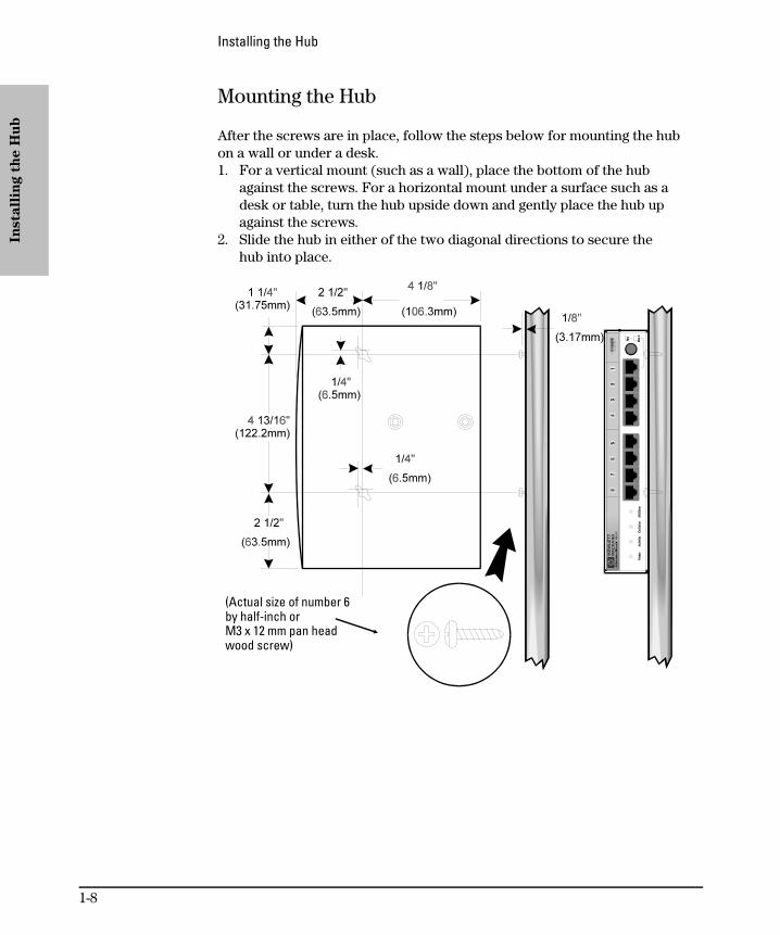
Mounting the Hub
After the screws are in place, follow the steps below for mounting the hubon a wall or under a desk. 1. For a vertical mount (such as a wall), place the bottom of the hub
against the screws. For a horizontal mount under a surface such as adesk or table, turn the hub upside down and gently place the hub upagainst the screws.
2. Slide the hub in either of the two diagonal directions to secure thehub into place.
(Actual size of number 6by half-inch or M3 x 12 mm pan headwood screw)
Insta
llin
g t
he H
ub
Installing the Hub
1-8

4. Complete the network connections to the hub
Reconnect the hub to the power source and then make the networkconnections to the hub. Typical hub connections are:
Hub-to-device connections. Connecting to network devices suchas computers and printers.
Hub-to-hub connections. Connecting to another HP AdvanceStackHub or other Ethernet hub.
Hub-to-network backbones. Connecting to a network backbone.
This section describes the different ways you can connect your hub to yournetwork.
Connecting Devices to the Hub
To connect a device to the hub, push the RJ-45 plug into the RJ-45 jack untilthe tab on the plug clicks into place.
RJ-45 plug
unshielded twisted-pair cable
to a computer or printer
Installin
g th
e H
ub
Installing the Hub
1-9
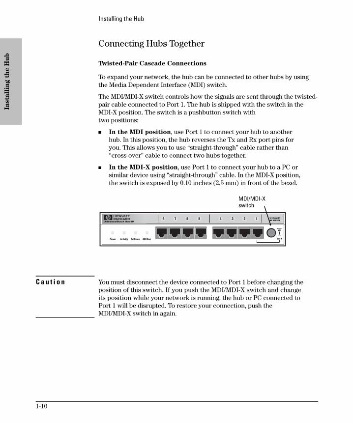
Connecting Hubs Together
Twisted-Pair Cascade Connections
To expand your network, the hub can be connected to other hubs by usingthe Media Dependent Interface (MDI) switch.
The MDI/MDI-X switch controls how the signals are sent through the twisted-pair cable connected to Port 1. The hub is shipped with the switch in theMDI-X position. The switch is a pushbutton switch with two positions:
In the MDI position, use Port 1 to connect your hub to anotherhub. In this position, the hub reverses the Tx and Rx port pins foryou. This allows you to use “straight-through” cable rather than“cross-over” cable to connect two hubs together.
In the MDI-X position, use Port 1 to connect your hub to a PC orsimilar device using “straight-through” cable. In the MDI-X position,the switch is exposed by 0.10 inches (2.5 mm) in front of the bezel.
C a u t i o n You must disconnect the device connected to Port 1 before changing theposition of this switch. If you push the MDI/MDI-X switch and changeits position while your network is running, the hub or PC connected toPort 1 will be disrupted. To restore your connection, push theMDI/MDI-X switch in again.
MDI/MDI-Xswitch
Insta
llin
g t
he H
ub
Installing the Hub
1-10

In the following illustration, the first hub is connected to two end nodes andto a second hub.
ThinLAN Connections
With an HP ThinLAN Transceiver Module for 10Base-2 networks, you canconnect your hub to a thinLAN network. The following illustration shows ahub with an HP ThinLAN Transceiver Module connected to a ThinLANbackbone.
Up to 100 meters
PC attached to Port 1:switch in MDI-X positionand straight-throughcable is used.
Hub attached to Port 1: switch in MDI position andstraight-through cable is used.
HP J2608A ThinLANTransceiver Module installedin the AUI/Xcvr Slot
thin coax cable
50-ohm terminator
Installin
g th
e H
ub
Installing the Hub
1-11

You can connect up to 30 hubs together on a common ThinLAN segment.The ThinLAN segment can include a computer attached to a hub at one endof the segment that can communicate with a computer attached to anotherhub at the other end of the segment. By using the BNC port on the module,the maximum repeater hop-count increment through the entire segment isonly two. The following illustration shows you how to connect three hubstogether from one ThinLAN port to another.
Connecting Hubs to Network Backbones
Connecting the Hub-8U to a ThinLAN Backbone
The optional ThinLAN Transceiver Module has a BNC 10Base-2 port that canbe used to connect your hub to a ThinLAN backbone.
ThinLAN coaxconnecting thehubs together
Hub-8U
Hub-8UHP AdvanceStack10Base-T Hub-24
50-ohmterminator
50-ohmterminator
Insta
llin
g t
he H
ub
Installing the Hub
1-12

The following illustration shows a hub with an HP ThinLAN TransceiverModule connected to a thinLAN backbone.
Connecting the Hub-8U to a Fiber-Optic Backbone
With an HP Fiber-Optic Transceiver Module for 10Base-FL networks, youcan connect your hub to a fiber-optic backbone. The following illustrationshows a hub with an HP Fiber-Optic Transceiver Module connected to a fiber-optic backbone:
For more information about cabling configuration, see the documentationaccompanying the optional transceiver modules.
See the Designing HP AdvanceStack Networks guide for information onvalid network topologies.
ThinLANbackbone
HP J2606A Fiber-OpticTransceiver Module installedin the AUI/Xcvr Slot
fiber-opticcable
Installin
g th
e H
ub
Installing the Hub
1-13

5. Connect the hub to an ASCII console (optional)
The optional HP AdvanceStack 8U/16U SNMP Module enables you toconfigure, monitor, and troubleshoot the hub from an ASCII console.
ASCII console
Insta
llin
g t
he H
ub
Installing the Hub
1-14

2
Troubleshooting
Troubleshooting Approaches
Diagnosing with the LEDs
Installation Problems
Cabling Problems
Unusual Network Activity
Diagnostic Tests
Customer Support Services
Replacement Instructions
This chapter describes how to diagnose and resolve operating problems withyour hub.
Additionally, if you have an HP J3133A AdvanceStack 8U/16U SNMP Moduleinstalled, you can use ASCII console software for certain diagnosticfunctions to troubleshoot the hub.
Troubleshooting Approaches
There are three primary ways to diagnose hub problems:
By checking the LEDs on the front of the hub as described in“Diagnosing with the LEDs” later in this chapter.
By visually inspecting the unit and all its connections as described inthe “Installation Problems” and “Cabling Problems” sections later inthis chapter.
By using the ASCII console’s diagnostic functions as described in thedocumentation shipped with the HP AdvanceStack 8U/16U SNMPModule, and in the software’s online help system.
Tro
ub
lesh
oo
tin
g
Troubleshooting
2-2

Diagnosing with the LEDs
Most problems with the hub can be diagnosed using the LEDs on its frontpanel. This section describes the normal LED pattern during self-test, andLED patterns that indicate error conditions on the hub.
LED Pattern During Self-Test
Whenever the hub is powered on or reset, it performs a self-diagnostic test.During the self-test, all of the LEDs turn on for a short time.
If an HP Transceiver module is properly installed, the AUI/Xcvr LED stayslit. If an HP Transceiver module is not installed, the AUI/Xcvr LED turns off.
When the self-test completes successfully, the LEDs go into their normaloperational states. If a hub hardware fault exists, the hub will not completeself-test. This will be indicated by an abnormal LED pattern.
The display of the Port LEDs pattern depends on whether the HP AdvanceS-tack 8U/16U SNMP Module is installed. If you have an HP AdvanceStack8U/16U SNMP Module installed, see the manual provided with the modulefor LED information.
The tables on the following two pages list the hub’s LEDs, their possiblestates, and diagnostic tips to resolve any error conditions. These tablesassume an HP AdvanceStack 8U/16U SNMP Module is not installed.
Tro
ub
lesh
oo
ting
Troubleshooting
2-3
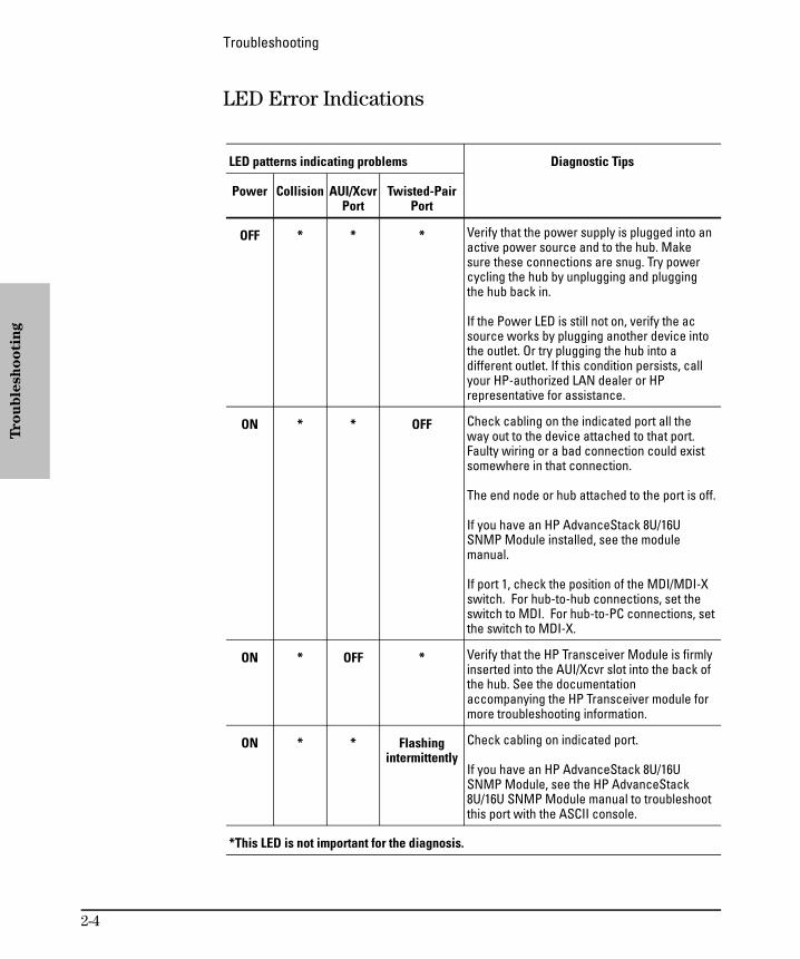
LED Error Indications
LED patterns indicating problems Diagnostic Tips
Power Collision AUI/XcvrPort
Twisted-PairPort
OFF * * * Verify that the power supply is plugged into anactive power source and to the hub. Makesure these connections are snug. Try powercycling the hub by unplugging and pluggingthe hub back in.
If the Power LED is still not on, verify the acsource works by plugging another device intothe outlet. Or try plugging the hub into adifferent outlet. If this condition persists, callyour HP-authorized LAN dealer or HPrepresentative for assistance.
ON * * OFF Check cabling on the indicated port all theway out to the device attached to that port.Faulty wiring or a bad connection could existsomewhere in that connection.
The end node or hub attached to the port is off.
If you have an HP AdvanceStack 8U/16USNMP Module installed, see the modulemanual.
If port 1, check the position of the MDI/MDI-Xswitch. For hub-to-hub connections, set theswitch to MDI. For hub-to-PC connections, setthe switch to MDI-X.
ON * OFF * Verify that the HP Transceiver Module is firmlyinserted into the AUI/Xcvr slot into the back ofthe hub. See the documentationaccompanying the HP Transceiver module formore troubleshooting information.
ON * * Flashingintermittently
Check cabling on indicated port.
If you have an HP AdvanceStack 8U/16USNMP Module, see the HP AdvanceStack8U/16U SNMP Module manual to troubleshootthis port with the ASCII console.
*This LED is not important for the diagnosis.
Tro
ub
lesh
oo
tin
g
Troubleshooting
2-4
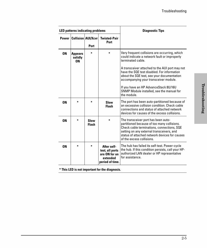
LED patterns indicating problems Diagnostic Tips
Power Collision AUI/Xcvr
Port
Twisted-PairPort
ON Appears solidly
ON
* * Very frequent collisions are occurring, whichcould indicate a network fault or improperlyterminated cable.
A transceiver attached to the AUI port may nothave the SQE test disabled. For informationabout the SQE test, see your documentationaccompanying your transceiver module.
If you have an HP AdvanceStack 8U/16USNMP Module installed, see the manual forthe module.
ON * * SlowFlash
The port has been auto-partitioned because ofan excessive collision condition. Check cableconnections and status of attached networkdevices for causes of the excess collisions.
ON * SlowFlash
* The transceiver port has been auto-partitioned because of too many collisions.Check cable terminations, connections, SQEsetting on any external transceivers, andstatus of attached network devices for causesof the excess collisions.
ON * * After self-test, all portsare ON for an
extendedperiod of time.
The hub has failed its self-test. Power-cyclethe hub. If this condition persists, call your HP-authorized LAN dealer or HP representativefor assistance.
* This LED is not important for the diagnosis.
Tro
ub
lesh
oo
ting
Troubleshooting
2-5

Installation Problems
By carefully following the installation procedures described in chapter 1,“Installing the Hub”, you can avoid most problems caused by improperinstallation of the hub or one of its components.
Incorrect Hardware Installation
Incorrectly installing the hub, ac power cord, power supply, the HP Ad-vanceStack 8U/16U SNMP Module, or a transceiver module can result in oneor all of these components malfunctioning or not functioning at all. If one orall of these components appear to not be functioning, re-check the installa-tion procedure and, if necessary, re-install the component correctly.
Cabling Problems
A high percentage of network problems are due to faulty cabling. Cablingproblems usually result in the failure of a hub to connect to a network,another hub, or the end nodes.
Connections
All cables attached to the hub should be checked to see that they areproperly connected. Proper network connections are described in chapter 1,“Installing the Hub”.
Properly connecting cables to the transceiver modules is described in thedocumentation that accompanies those modules.
If you are using the optional HP ThinLAN Transceiver Module, be certainthat the thin coax segment attached to the port is properly terminated with a 50-ohm terminator at both ends, as described in the manual accompanyingthe transceiver module.
Tro
ub
lesh
oo
tin
g
Troubleshooting
2-6

Non-standard Cables
Mis-wired cables may cause numerous network collisions, and can seriouslyimpair network performance. Before connecting cables into your network,you should verify that they comply with the applicable standards. For a listof compatible cables and a description of the pinouts for each port on thehub (which can be used to confirm the compatibility of unlisted cables), seeappendix A, “Cables and Connectors”.
Topology
It is important to make sure you have a valid network topology. Commontopology faults include excessive cable length and excessive repeater delaysbetween nodes. If you have trouble after recent changes to a network,switch back to the previous topology. If you no longer have any trouble, thenew topology is probably at fault. Refer to the guide entitled Designing
HP AdvanceStack Networks for topology configuration guidelines. Contactyour HP-authorized LAN dealer or local HP sales office to get a copy of thisguide.
Unusual Network Activity
Network activity that exceeds accepted norms often indicates a hardwareproblem with one or more of the network components, possibly includingthe hub. Unusual network activity is usually indicated by the LEDs on thefront of the hub or measured with one of the diagnostic tools in the ASCIIconsole. Refer to “Diagnosing with LEDs” earlier in this chapter forinformation on using LEDs to identify unusual network activity.
Tro
ub
lesh
oo
ting
Troubleshooting
2-7

Diagnostic Tests
If you have an HP AdvanceStack 8U/16U SNMP Module installed into thehub, the ASCII console provides tests and indicators that can be used tomonitor the hub and its network connections. See the documentation shippedwith the HP AdvanceStack 8U/16U SNMP Module and the console’s onlineHelp system for more details about these tests and indicators.
Testing the Hub Only
If you believe that the hub is not operating correctly, you can test the hub’scircuitry by resetting the hub through one of these procedures:
Unplug the ac adapter from the hub and plug the ac adapter into thehub again.
If an HP AdvanceStack 8U/16U SNMP Module is installed, select the“Reset” option from the ASCII console or press the Reset button onthe module..
Each of these procedures will power-cycle the hub and execute its self-test.If all of the Port LEDs stay on after 3 seconds, the hub may have failed itsself-test. See “Diagnosing with the LEDs” earlier in this chapter to interpretthe LED display.
C a u t i o n Cycling power on the hub will temporarily disable the network andcould have other adverse effects.
Testing Twisted-Pair Cabling
The twisted-pair cable attached to the hub must be compatible with theIEEE 802.3 Type 10Base-T standard. To verify that your cable is compatiblewith this standard, you can use the HP J2263A Cable Test Set. The older HP28687A Wire Test Instrument can also be used. HP also offers a wire testingservice. Contact your HP-authorized LAN dealer or your local HP sales officefor more information.
Tro
ub
lesh
oo
tin
g
Troubleshooting
2-8

Testing End-to-End Network Communications
Both the hub and the cabling can be tested by running an end-to-endcommunications test — a test that sends known data from one networkdevice to another through the hub — such that you can verify that the datawas correctly transmitted between the devices. For example, if you havetwo PCs on the network that have HP LAN adapter cards, you can use the“Link Test” option from the card’s test program to verify the entire communi-cation path between the two PCs. In the following illustration, two computersare connected together with twisted-pair cable to two different ports on thehub.
See your LAN adapter card’s manual for information on running an end-to-endcommunication test.
With the AdvanceStack 8U/16U SNMP module, you can also run a Link testdirectly to or from a hub (directly between a hub and another device, ratherthan just through the hub).
PC sendingtest packets
PC responding tothe test packets
Tro
ub
lesh
oo
ting
Troubleshooting
2-9
Replacement Instructions
Remove any of the optional modules that you have installed into your hubbefore returning it to Hewlett-Packard. Keep the optional modules to installthem into the replacement hub.
The modules can be damaged easily by small amounts of static electricity.Observe these precautions when removing and installing the modules:
When handling the module, first touch a grounded metal surface, orwear an anti-static wrist strap that is attached to grounded metal.
To prevent generating static electricity, minimize your movementaround the work area, or work in an anti-static work area.
Handle the module carefully at all times. Avoid flexing it or touchingits components.
The faulty hub should be returned to Hewlett-Packard with the AUI/Xcvrand management slots empty and the cover plates installed.
For information about how to remove the modules, see the manualsaccompanying the HP Transceiver Module and the HP AdvanceStack 8U/16USNMP Module.
Tro
ub
lesh
oo
tin
g
Troubleshooting
2-10
Customer Support Services
Hewlett-Packard offers support 24 hours a day, seven days a week throughthe use of automated electronic services including:
World Wide Web
Hewlett-Packard FTP Library Service on the Internet
CompuServ
Hewlett-Packard BBS
HP FIRST FAX Retrieval Service
HP Network Phone-In Support (NPS)
SNMP firmware for the AdvanceStack 8U/16U SNMP module (j3133a.exe) isavailable through several of the above services. Refer to the card at the frontof this manual.
Tro
ub
lesh
oo
ting
Troubleshooting
2-11


3
Hub Reference
Front of the Hub
Back of the Hub
Hub Operation

Front of the Hub
Hub status LEDs
The hub status LEDs indicate whether the hub is functioning properly. Forfurther details on error conditions indicated by the Status LEDs, see chapter2, “Troubleshooting”.
LED State Meaning of LED
Power (green)
On The hub is receiving power.
Off The hub is not receiving power.
Activity (green)
Flickering ON while a packet is being transmitted. Normally, the LEDappears to flicker. In heavy traffic, it may appear on all the time.
Collision(orange)
Flickering This LED is on while a collision is detected on any of the attachedcable segments. If collisions are infrequent (which is normal) thelight may be imperceptible. In a network with heavy traffic, theLED will glow and flicker dimly, indicating collisions areoccurring. If it appears on continuously (with no flicker), it is apossible indicator of a network fault. See chapter 2,“Troubleshooting”.
Hu
b R
efe
ren
ce
Hub Reference
3-2
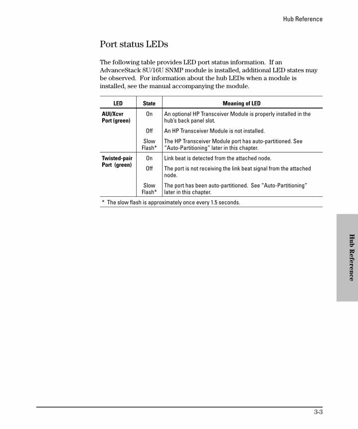
Port status LEDs
The following table provides LED port status information. If an AdvanceStack 8U/16U SNMP module is installed, additional LED states maybe observed. For information about the hub LEDs when a module isinstalled, see the manual accompanying the module.
LED State Meaning of LED
AUI/Xcvr Port (green)
On An optional HP Transceiver Module is properly installed in thehub’s back panel slot.
Off An HP Transceiver Module is not installed.
SlowFlash*
The HP Transceiver Module port has auto-partitioned. See“Auto-Partitioning” later in this chapter.
Twisted-pairPort (green)
On Link beat is detected from the attached node.
Off The port is not receiving the link beat signal from the attachednode.
SlowFlash*
The port has been auto-partitioned. See “Auto-Partitioning”later in this chapter.
* The slow flash is approximately once every 1.5 seconds.
Hu
b R
efe
ren
ce
Hub Reference
3-3

Back of the hub
The back of the hub has two slots: the Management Slot and the AUI/XcvrSlot.
Management Slot
The management slot is used to add an HP J3133A AdvanceStack 8U/16USNMP Module. For more information, see the “Install Add-in Modules”section in chapter 1.
AUI/Xcvr Slot
The AUI/Xcvr Slot is used to add an HP Transceiver Module. For moreinformation, see the “Install Add-in Modules” section in chapter 1.
Hu
b R
efe
ren
ce
Hub Reference
3-4

Hub Operation
The HP AdvanceStack Hub-8U is a multiport repeater that conforms to theIEEE 802.3 repeater specification. Data signals coming into the hub fromany of its ports are automatically regenerated and transmitted to all theother hub network ports. The hub regenerates the data without interpretingthe contents, so it can be used in either IEEE 802.3 or Ethernet networksand with any upper-level protocol.
Collision Detection
The hub also performs collision detection. A collision occurs when twonodes try to transmit at the same time. When the hub detects a collision, itstops repeating the colliding transmissions and starts transmitting a jammingsignal. The jamming signal tells the transmitting nodes that a collision hasoccurred. The colliding nodes then stop transmitting for a random amount oftime before attempting to retransmit the data. Once the collision condition isremoved, the hub stops transmitting the jamming signal and normal operationis resumed.
Auto-Partitioning
The hub will automatically partition (temporarily disable) one of its ports ifa collision condition exists for an excessive duration (between 1024 and2048 bit times) or occurs during each of 32 consecutive attempts to transmit.The hub monitors the partitioned port and automatically re-enables the portwhen a minimum length packet can be successfully transmitted or receivedwithout a collision occurring.
Excessive collisions may be caused by faulty wiring. If a port’s transmit (Tx +/-) wires have been shorted to the receive (Rx +/-) wires of any port, a collision will be detected when that port attempts to transmit. If a port’sreceive (Rx +/-) wires are not connected properly, collisions may occurbecause the hub cannot detect the presence of network traffic on that portand may thus transmit at inappropriate times.
A port may occasionally also become partitioned when network traffic isextremely heavy causing an abnormally high collision rate.
Hu
b R
efe
ren
ce
Hub Reference
3-5

Link Beat
Type 10Base-T devices use a signal called link beat (also called link testpulse). This signal informs the hub of the presence of a device connected toit over twisted-pair cable and of the integrity of the twisted-pair link betweenthem. The hub will not transmit packets out of twisted-pair ports that do notsense the link beat signal.
Hu
b R
efe
ren
ce
Hub Reference
3-6

A
Cables and Connectors
Recommended Cables
Twisted-Pair Cable/Connector Pin-Outs
ThinLAN Requirements
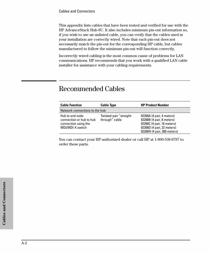
This appendix lists cables that have been tested and verified for use with theHP AdvanceStack Hub-8U. It also includes minimum pin-out information so,if you wish to use an unlisted cable, you can verify that the cables used inyour installation are correctly wired. Note that each pin-out does notnecessarily match the pin-out for the corresponding HP cable, but cablesmanufactured to follow the minimum pin-out will function correctly.
Incorrectly wired cabling is the most common cause of problems for LANcommunications. HP recommends that you work with a qualified LAN cableinstaller for assistance with your cabling requirements.
Recommended Cables
Cable Function Cable Type HP Product Number
Network connections to the hub:Hub to end nodeconnection or hub to hubconnection using theMDI/MDI-X switch
Twisted-pair “straight-through” cable
92268A (4 pair, 4 meters)92268B (4 pair, 8 meters)92268C (4 pair, 16 meters)92268D (4 pair, 32 meters)92268N (4 pair, 300 meters)
You can contact your HP-authorized dealer or call HP at 1-800-538-8787 toorder these parts.
Cab
les a
nd
Co
nn
ecto
rs
Cables and Connectors
A-2

Twisted-Pair Cable/Connector Pin-Outs
Twisted-Pair Cable for Hub-to-ComputerNetwork Connection
To connect PCs or other network devices to the hub, use a “straight-through”10Base-T cable. The twisted-pair wires must be twisted through the entirelength of the cable. The wiring sequence must conform to AT&T 258A (notUSOC). See “Twisted-Pair Cable Pin Assignments” later in this chapter for alisting of the signals used on each pin.
N o t e Pins 1 and 2 must be a twisted pair.Pins 3 and 6 must be a twisted pair.
Pins 4, 5, 7, and 8 are not used in this application, although they may bewired in the cable.
Straight-through cable
white/orange
orange/white
white/green
green/white
Cab
les a
nd
Co
nn
ecto
rs
Cables and Connectors
A-3
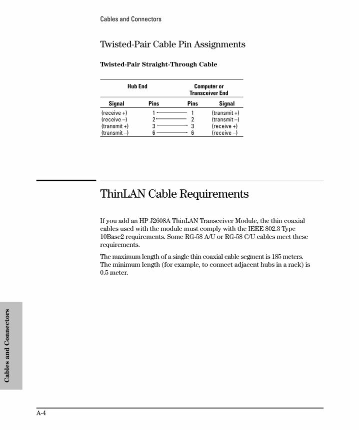
Twisted-Pair Cable Pin Assignments
Twisted-Pair Straight-Through Cable
Hub End Computer orTransceiver End
Signal Pins Pins Signal
(receive +)(receive –)(transmit +)(transmit –)
1236
1236
(transmit +)(transmit –)(receive +)(receive –)
ThinLAN Cable Requirements
If you add an HP J2608A ThinLAN Transceiver Module, the thin coaxialcables used with the module must comply with the IEEE 802.3 Type 10Base2 requirements. Some RG-58 A/U or RG-58 C/U cables meet theserequirements.
The maximum length of a single thin coaxial cable segment is 185 meters. The minimum length (for example, to connect adjacent hubs in a rack) is 0.5 meter.
Cab
les a
nd
Co
nn
ecto
rs
Cables and Connectors
A-4

B
Specifications
Physical
Electrical
Environmental
Connectors
Electromagnetic

Physical
Width: 21.6 cm (8.5 in) Height: 4.1 cm (1.6 in)Depth: 17.0 cm (6.7 in) Weight: 0.8 kg (1.5 lb)
Electrical
ac voltage: 100-240 voltsMaximum current: 0.7 A max Frequency range: 47/63 Hz
Environmental
Operating Non-OperatingTemperature: 0°C to 55°C
(32°F to 131°F)-40°C to 70°C(-40°F to 158°F)
Relative humidity: (non-condensing)
15% to 95%at 40°C (104°F)
15% to 90%at 65°C (149°F)
Maximum altitude: 4.6 km (15,000 ft) 4.6 km (15,000 ft)
Connectors
The RJ-45 twisted-pair ports are compatible with the IEEE 802.3Type 10Base-T standard.
Safety
Complies with:IEC 950: (1991)+A1,A2/.EN60950 I(1992)+A1,A2UL1950CSA 950NOM-019-SCFI-1994NOM-001-SCFI-1993
Sp
ecif
icati
on
s
Specifications
B-2

Electromagnetic
EmissionsFCC part 15 Class AEN 55022 Class A / CISPR-22 Class AVCCI Level IComplies with Canadian EMC Class A requirements
ImmunitySee the Declaration of Conformity for details at the end of the Regulatory Statements.
Accoustic NoiseNot applicable
Sp
ecific
atio
ns
Specifications
B-3


C
Safety and Regulatory Statements
This chapter covers the following topics:
Safety and Regulatory Statements
Declaration of Conformity
Safety Information
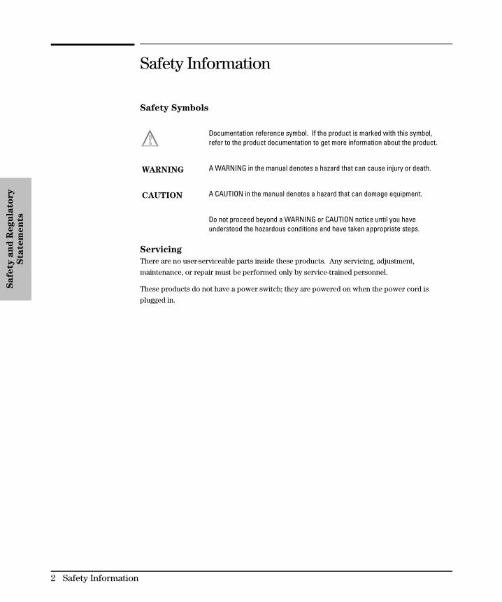
Safety Symbols
Documentation reference symbol. If the product is marked with this symbol, refer to the product documentation to get more information about the product.
WARNING A WARNING in the manual denotes a hazard that can cause injury or death.
CAUTION A CAUTION in the manual denotes a hazard that can damage equipment.
Do not proceed beyond a WARNING or CAUTION notice until you haveunderstood the hazardous conditions and have taken appropriate steps.
Servicing
There are no user-serviceable parts inside these products. Any servicing, adjustment,
maintenance, or repair must be performed only by service-trained personnel.
These products do not have a power switch; they are powered on when the power cord is
plugged in.
Safe
ty a
nd
Regu
lato
ry
Sta
tem
en
ts
2 Safety Information

Informations concernant la sécurité
Symboles de sécurité
Symbole de référence à la documentation. Si le produit est marqué de cesymbole, reportez-vous à la documentation du produit afin d’obtenir desinformations plus détaillées.
WARNING Dans la documentation, un WARNING indique un danger susceptible d’entraînerdes dommages corporels ou la mort.
CAUTION Un texte de mise en garde intitulé CAUTION indique un danger susceptible de causer des dommages à l’équipement.
Ne continuez pas au-delà d’une rubrique WARNING ou CAUTION avant d’avoir bien compris les conditions présentant un danger et pris les mesuresappropriées.
Aucune pièce contenue à l’intérieur de ce produit ne peut être réparée par l’utilisateur. Tout
dépannage, réglage, entretien ou réparation devra être confié exclusivement à un personnel
qualifié.
Cet appareil ne comporte pas de commutateur principal ; la mise sous tension est effectuée
par branchement du cordon d’alimentation.
Safe
ty a
nd
Regu
lato
ry
Sta
tem
en
ts
Informations concernant la sécurité 3

Hinweise zur Sicherheit
Sicherheitssymbole
Symbol für Dokumentationsverweis. Wenn das Produkt mit diesem Symbolmarkiert ist, schlagen Sie bitte in der Produktdokumentation nach, um mehrInformationen über das Produkt zu erhalten.
WARNING Eine WARNING in der Dokumentation symbolisiert eine Gefahr, die Verletzungenoder sogar Todesfälle verursachen kann.
CAUTION CAUTION in der Dokumentation symbolisiert eine Gefahr, die das Gerätbeschädigen kann.
Fahren Sie nach dem Hinweis WARNING oder CAUTION erst fort, nachdem Sieden Gefahrenzustand verstanden und die entsprechenden Maßnahmen ergriffenhaben.
Dieses Gerät enthält innen keine durch den Benutzer zu wartenden Teile. Wartungs-,
Anpassungs-, Instandhaltungs- oder Reparaturarbeiten dürfen nur von geschultem
Bedienungspersonal durchgeführt werden.
Dieses Gerät hat keinen Netzschalter; es wird beim Anschließen des Netzkabels eingeschaltet.
Safe
ty a
nd
Regu
lato
ry
Sta
tem
en
ts
4 Hinweise zur Sicherheit
Considerazioni sulla sicurezza
Simboli di sicurezza
Simbolo di riferimento alla documentazione. Se il prodotto è contrassegnato daquesto simbolo, fare riferimento alla documentazione sul prodotto per ulterioriinformazioni su di esso.
WARNING La dicitura WARNING denota un pericolo che può causare lesioni o morte.
CAUTION La dicitura CAUTION denota un pericolo che può danneggiare le attrezzature.
Non procedere oltre un avviso di WARNING o di CAUTION prima di avercompreso le condizioni di rischio e aver provveduto alle misure del caso.
Nessun componente di questo prodotto può essere riparato dall’utente. Qualsiasi lavoro
di riparazione, messa a punto, manutenzione o assistenza va effettuato esclusivamente
da personale specializzato.
Questo apparato non possiede un commutatore principale; si mette scotto tensione all’inserirsi
il cavo d’alimentazione.
Safe
ty a
nd
Regu
lato
ry
Sta
tem
en
ts
Considerazioni sulla sicurezza 5

Consideraciones sobre seguridad
Símbolos de seguridad
Símbolo de referencia a la documentación. Si el producto va marcado con este símbolo, consultar la documentación del producto a fin de obtenermayor información sobre el producto.
WARNING Una WARNING en la documentación señala un riesgo que podría resultar enlesiones o la muerte.
CAUTION Una CAUTION en la documentación señala un riesgo que podría resultar enaverías al equipo.
No proseguir después de un símbolo de WARNING o CAUTION hasta no haber entendido las condiciones peligrosas y haber tomado las medidasapropiadas.
Este aparato no contiene pieza alguna susceptible de reparación por parte del usuario.
Todas las reparaciones, ajustes o servicio de mantenimiento debe realizarlos solamente
el técnico.
Este producto no tiene interruptor de potencia; se activa cuando se enchufa el cable de
alimentación.
Safe
ty a
nd
Regu
lato
ry
Sta
tem
en
ts
6 Consideraciones sobre seguridad

Safety Information
Safe
ty a
nd
Regu
lato
ry
Sta
tem
en
ts
Safety Information 7

Regulatory Statements
FCC Statement (For U.S.A. Only)
Federal Communications Commission Radio Frequency Interference
Statement
Warning: This equipment generates, uses, and can radiate radio frequency energy. If it is not
installed and used in accordance with the instruction manual, it may cause interference to radio
communications. It has been tested and found to comply with the limits for a Class A comput-
ing device pursuant to Part 15 of FCC Rules, which are designed to provide reasonable protec-
tion against such interference when operated in a commercial environment. Operation of this
equipment in a residential area is likely to cause interference, in which case the user at his own
expense will be required to take whatever measures may be required to correct the interference.
If this equipment causes interference to radio reception (which can be determined by unplug-
ging the power cord from the equipment) try these measures: Re-orient the receiving antenna.
Relocate the equipment with respect to the receiver. Plug the equipment and receiver into differ-
ent branch circuits. Consult your dealer or an experienced technician for additional sugges-
tions.
VCCI Class 1 (For Japan Only)
N o t e This is a class A product. In a domestic environment, this product maycause radio interference, in which case the user may be required to takeadequate measures.
Safe
ty a
nd
Regu
lato
ry
Sta
tem
en
ts
8 Regulatory Statements

Safe
ty a
nd
Regu
lato
ry
Sta
tem
en
ts
Regulatory Statements 9
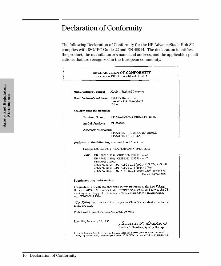
Declaration of Conformity
The following Declaration of Conformity for the HP AdvanceStack Hub-8Ucomplies with ISO/IEC Guide 22 and EN 45014. The declaration identifiesthe product, the manufacturer’s name and address, and the applicable specifi-cations that are recognized in the European community.
Safe
ty a
nd
Regu
lato
ry
Sta
tem
en
ts
10 Declaration of Conformity

Index

A
ac adapterplugging into the hub, 1-5, C-2plugging into the wall, 1-5
Activity LED, 3-2AdvanceStack Assistant, vat a glance, iiiASCII console, 1-14AUI/Xcvr LED, 3-3AUI/Xcvr slot, 3-4auto-partitioning
basic operation, 3-5
B
back of the hubinstalling optional modules, 1-3
BBSobtaining software from, 2-11
brackets, mountinghow to order, 1-8
bulletin boardobtaining software from, 2-11
C
cablescabling problems, 2-6network connections, A-2twisted-pair connector pin-outs, A-3
cables and connections, A-2collision detection, 3-5Collision LED, 3-2CompuServe
obtaining files from, 2-11connections
hub-to-hub networking, 1-10network, 1-9out-of-band management, 1-14
connector specifications, B-2countries
ac adapters for, 1-2customer service
types of, 2-11
D
Declaration of Conformity, C-10description, iii
diagnosing with the LEDs, 2-3diagnostic tests, 2-8
testing the hub only, 2-8testing twisted-pair cabling, 2-8
E
electrical specifications, B-2electromagnetic specifications, B-2environmental specifications, B-2, C-2Ethernet networks, iiiexternal power supply, 1-2
F
faxusing to get HP product information, 2-11
features, vfiber-optic backbone, 1-13front of the hub
status LEDs, 3-2ftp
obtaining files from HP, 2-11
H
Hourly supportcalling for, 2-14
HP AdvanceStack SNMP ModuleLED pattern during self-test, 2-3part of hub installation, 1-3
HP FIRST FAX Retrieval Serviceusing, 2-14
HP FTP Library Serviceusing, 2-12
hubat a glance, iiicables, A-2connecting to fiber-optic backbone, 1-13connecting to network backbones, 1-12description, iiifeatures, vincluded parts, 1-2installation problems, 2-6installing, 1-2mounting, 1-7, C-2operation, 3-5replacing, 2-10specifications, B-2troubleshooting, 2-2
Ind
ex
Index
Index-2

hub operationauto-partitioning, 3-5collision detection, 3-5link beat, 3-6verifying, 1-5
Hub-8UThinLAN connections, 1-11
hub-to-hub network connectionsusing the ThinLAN port, 1-14with the MDI switch, 1-10
I
IEEE 802.3 Type 10Base-T standard, iiiincluded parts, 1-2installation problems, 2-6installing the hub
equipment needed, 1-7mounting procedures, 1-7, C-2network connections, 1-9out-of-band management connections, 1-14summary of steps, 1-2verifying hub operation, 1-5wall mounting, 1-7
Internetobtaining latest drivers from, 2-12obtaining software from, 2-11
L
LAN adapter cardsto test end-to-end communications, 2-9
LEDsActivity, 3-2AUI/Xcvr, 3-3Collision, 3-2diagnosing the hub status, 2-3pattern during self test, 2-3patterns showing error conditions, 2-4Power, 3-2twisted-pair ports, 3-3verifying hub operation, 1-6
link beatdescription, 3-6
listincluded parts, 1-2
M
management slot, 3-4managing the hub, 1-14
MDI switch, using, 1-10MDI-X switch, using, 1-10mounting brackets
ordering, 1-8mounting the hub, 1-7
precautions, 1-7under a desk, 1-8wall mounting, 1-7
N
Network backbones, 1-12network connections
hub-to-hub connections, 1-10port connections, 1-9
network management, vnon-standard cables, 2-7
O
operation of the hubdescription, 3-5
out-of-band managementconnecting to the hub, 1-14
P
partitioningautomatic partitioning of ports, 3-5
parts list, 1-2physical specifications of hubs, B-2port LEDs
twisted-pair, 3-3ports
connection procedures, 1-9power
LED pattern during, 2-3Precautions, 1-3, 1-5
Power LED, 3-2precautions for mounting the hub, 1-7procedures
hub installation, 1-2network connections to the hub, 1-9network port connections , 1-9wall mounting the hub, 1-7
Ind
ex
Index
Index-3

R
recommended cables, A-2Regulatory statements, C-9replacement
of the hub, 2-10resetting the hub
troubleshooting procedure, 2-8
S
Safety information, C-2screws
description, 1-7specifications
connectors, B-2electrical, B-2electromagnetic, B-2environmental, B-2physical, B-2
status LEDsdescription, 3-2
summaryinstallation steps, 1-2
T
technical supporttypes of, 2-11
testing twisted-pair cabling, 2-8ThinLAN connections, 1-11ThinLAN port
cable requirements, A-4topology faults, 2-7transceiver modules
part of hub installation, 1-3troubleshooting
approaches, 2-2ASCII console, 2-8cabling problems, 2-6diagnosing with the LEDs, 2-3diagnostic tests, 2-8installation problems, 2-6LED pattern during power-on, 2-3LED patterns showing errors, 2-4testing the hub, 2-8testing the twisted-pair cables, 2-8topology faults, 2-7unusual network activity, 2-7
twisted-pair cablehub-to-computer connection, A-3pin assignments, A-4pin-outs, A-3testing, 2-8
twisted-pair portsLED description, 3-3
U
unusual network activity, 2-7
V
verifying hub operation, 1-5
W
wall mounting the hub, 1-7World Wide Web
obtaining software from, 2-11WWW
obtaining software from, 2-11
Ind
ex
Index
Index-4


© 1997 Hewlett-Packard CompanyPrinted in U.S.A. 7/97
Manual Part NumberJ2610-90201, Edition 1
*J2610-90201*
H©