installation and owner’s manual · a reverse osmosis (ro) membrane is a semi-permanent synthetic...
TRANSCRIPT
0
INSTALLATION AND OWNER’S MANUAL
For Drinking Water Systems
THIS MANUAL IS TO BE LEFT WITH THE OWNER OF THE EQUIPMENT FOR REFERENCE PURPOSES AND TECHNICAL GUIDANCE. IT IS STRONGLY RECOMMENDED THAT QUALIFIED DEALER SERVICE PERSONNEL BE CONTACTED IN THE EVENT OF AN UNKNOWN INTERRUPTION OF SERVICE OR APPARENT PRODUCT MALFUNCTION. AN ANNUAL PREVENTATIVE MAINTENANCE INSPECTION BY A WATER PROFESSIONAL IS RECOMMENDED TO ENSURE TROUBLE-FREE AND CONTINUOUS OPERATION.
1
Congratulations! You have purchased the finest residential drinking water system available for your home. It will provide you years of reliable service if properly installed, operated and maintained. Please read this entire manual before attempting installation and operation.
Section 1. Frequently Asked Questions Before getting started, take the time to familiarize yourself with your new Purifiner VECTATWISTTM system by reading some FAQs listed below. Call us or ask your dealer if you have any other questions about your system’s operation. Q: How does your Vectatwist™ Drinking Water System differ from an ordinary water filter? Ordinary water filters use a cartridge or membrane contained in a sump or housing to filter your drinking water. Cartridge or membrane changes require housing wrenches and manual insertion of the cartridges into the housings. VectatwistTM systems use a convenient quarter-turn bayonet style cartridge that may be easily changed without any system disassembly. Your system will deliver pure, bottled water quality water to a faucet conveniently located at your kitchen sink or any other designated area. Q: What is a membrane and how does it work? A reverse osmosis (RO) membrane is a semi-permanent synthetic film that is spiral wound and separates raw water from product water (permeate). Water containing dissolved contaminants and salts is forced though the membrane by water pressure, with pure water being collected in the storage tank and rejected contaminants flushed to waste. Q: What processes does the VectatwistTM systems use? Vectatwist™ systems use combinations of 4 types of treatment to produce your drinking water. 5-micron polypropylene (PP) particle filters remove dirt, rust and other sediment. Activated carbon cartridges (granular carbon in GAC and moulded briquettes in CBC) remove chlorine, colour, taste, odours and other contaminants. RO membranes will reduce concentrations of dissolved ions in the water by up to 99.9%. Q: Will membranes remove minerals and salts from the water? Reverse Osmosis (RO) membranes will remove up to 99.9% of common salts in solution. Q: Does membrane filtration remove bacteria? Cryptosporidium? Viruses? Yes. RO membranes will eliminate most bacteria, viruses and parasites such as Cryptosporidium from the water. However, where these conditions exist, pre-filters and other system components located before the membrane will become contaminated from exposure to them. Cross contamination of the entire system may occur when the membrane or filters are changed or disturbed.

2
! VECTATWIST™ DRINKING WATER SYSTEMS ARE DESIGNED ONLY TO IMPROVE AESTHETIC PROPERTIES AND IS NOT DESIGNED TO ACT AS A PRIMARY BARRIER TO WATERBORNE MICROBIOLOGICAL OR TOXIC CHEMICAL CONTAMINATION. WHERE THESE CONDITIONS MAY EXIST CONSULT A WATER PROFESSIONAL TO ENSURE SUFFICIENT RAW WATER PRE-TREATMENT AND DISINFECTION.
Q: Where is the system installed? Typically, the system is installed under the kitchen sink. This will be handy for most homeowners, for Vectatwist™ systems are compact and take up very little space. Some homeowners or installers prefer the basement or crawlspace, as this conserves storage in the kitchen and may allow for easier access to the system for maintenance purposes. If you install the system more that 20’ from your faucet, you may need a booster pump to ensure adequate pressure at the faucet. Your dealer can provide you with this optional equipment. Q: Can the Vectatwist™ system be connected to an extra faucet? Yes. Many installations may include an optional ¼” tee and line to connect refrigerator icemakers or additional sink faucets. (Note: Most refrigerator manufacturers require a minimum of 20 psi for their ice maker to work. In high volume and/or low-pressure applications, the use of a booster pump on the treated water may be necessary) See your dealer for advice and parts. Q: How much water does the Vectatwist™ system produce? A VectatwistTM RO system will nominally produce 300-350 US gallons (1130-1325 litres) of product water per day. This output will be affected by system pressure, concentration of dissolved salts in the raw water, raw water temperature and other localized factors. Normally, you can expect the system to produce 45 to 55 litres of water per hour. Q: What is the standard warranty with Vectatwist™ systems? Every Vectatwist™ system comes with a standard one-year limited warranty on all parts and repair labour. A detailed warranty card is included with the unit. You may purchase an extended consumer warranty if you wish - see the enclosed Extended Warranty Program information sheet and enrolment form included in your package. Call your dealer or go to www.waterite.com to apply. Normal filter cartridge replacement is excluded from your warranty. Q: What is the cartridge replacement schedule for a Vectatwist™ system? A good rule of thumb is to replace filter cartridges (green and blue cartridges) every three months. RO membranes have a life usually ranging from one year to as much as five to seven years, dependent upon local water conditions Slow storage tank refill rates on RO systems are an indicator that the membrane may require replacement.
Section 2. Unpacking and Installation Your system includes:
Carton Contents (Fig 1A) The main 4 stage RO/filter unit assembly; One encapsulated membrane (pre-installed), one sediment filter cartridge, two carbon block
filter cartridges; One drain fitting and clamp with push-on tube fitting;

3
One cold water supply adapter; One ¼” shutoff valve push fit One long reach faucet with mounting hardware; Two #10 X1” Wall mounting screws; 5 m (15’) - white ¼” Poly tubing for water connections; 3m (10’) – black ¼” Poly tubing for drain connections; One plastic tank shut-off valve; One Owner’s package including owner’s manual, warranty certificate, Extended Warranty
Plan enrolment form, Waterite Parts Program enrolment form; One 12 litre (4 gallon) RO holding tank.
Step 1. Selecting the System Location
1. Your VectatwistTM filtration system is designed for installation under a sink. It can however, be mounted anywhere within 20 feet of the faucet, such as the basement or adjoining utility room. Keep in mind that filter cartridges will need periodic replacement and that easy access must be maintained. Do not install in a location with high humidity, heat or direct sun.
2. The two mounting holes are 13.5” centers for a 4 stage and 15” centers for a 5 stage. Use the #10x1” lag screws and washers supplied
Figure 1A.
Mounting Bracket RO Membrane Sediment Cartridge (blue) Sani-purge Cartridge Storage Tank PE Tubing Carbon Block Cartridge
(green) Faucet Drain Line Faucet Mounting Kit Tank Valve Cold Water line Pressure Reducing Adapter Valve Mounting Screws
Drain Line Saddle Kit Keep in mind that you may install a tube tee on the line to the faucet to connect icemakers or other faucets to the system. If you locate your system farther than 20 feet from the faucet, you will need to add a pressure booster pump to your system. See your dealer for parts and details
Step 2. Getting Ready 1. Clear working area. Unpack all components and check for visual damage. Ensure all listed
components are included. 2. Inspect the cold-water supply line and the condition of the pipe. If you have a polybutylene,
polypropylene, iron or a PEX supply line, you will need to consult your plumber or plumbing supply store to purchase an appropriate cold-water connection.
VectatwistTM four-stage RO shown b
4
3. You will need the following tools: An electric drill, a 1/2” drill bit, a 1/8” drill bit, a pencil, a small adjustable (crescent) wrench, a sharp knife (X-Acto type knife is best), adjustable pliers, a Phillips-head screwdriver, a rat-tail file, a center punch. Always wear eye protection when using an electric drill.
Step 3. Install the Cold Water Supply Adapter
1. Turn OFF the COLD water supply valve to your kitchen faucet.
2. Turn ON the COLD water on your kitchen faucet to release all the pressure, and completely drain the cold water until the water flow stops.
3. Place some towels underneath the cold-water supply valve and then disconnect the faucet supply tube from the cold water supply valve.
4. Wrap the male threads on both cold water supply valve and the cold water supply adapter 4 to 5 times with plumber’s (Teflon) tape.
5. Ensuring the gasket is in the female end, install the water supply adapter on the cold-water supply valve. Do not over-tighten.
6. Install the faucet supply tube to the water supply adapter. Do not over-tighten. 7. If the shutoff valve is pre-installed skip to step 3.10
8. If the shut off valve is not installed, cut a piece of clear tubing 1.5-2” long. Connect this tube
into the side push fit port of the water supply adapter by inserting the tube firmly and pushing until the tube end contacts the stop. Gently tug the tube backwards to assure a secure connection. Do NOT connect the other end of the tube to the RO system water inlet at this time.
9. Install the ¼” shutoff valve to the other end of the cut tubing by inserting the tube firmly and pushing until the tube end contacts the stop. Gently tug the tube backwards to assure a secure connection.
10. Keep the COLD water supply valve OFF until the RO system installation has been completed.
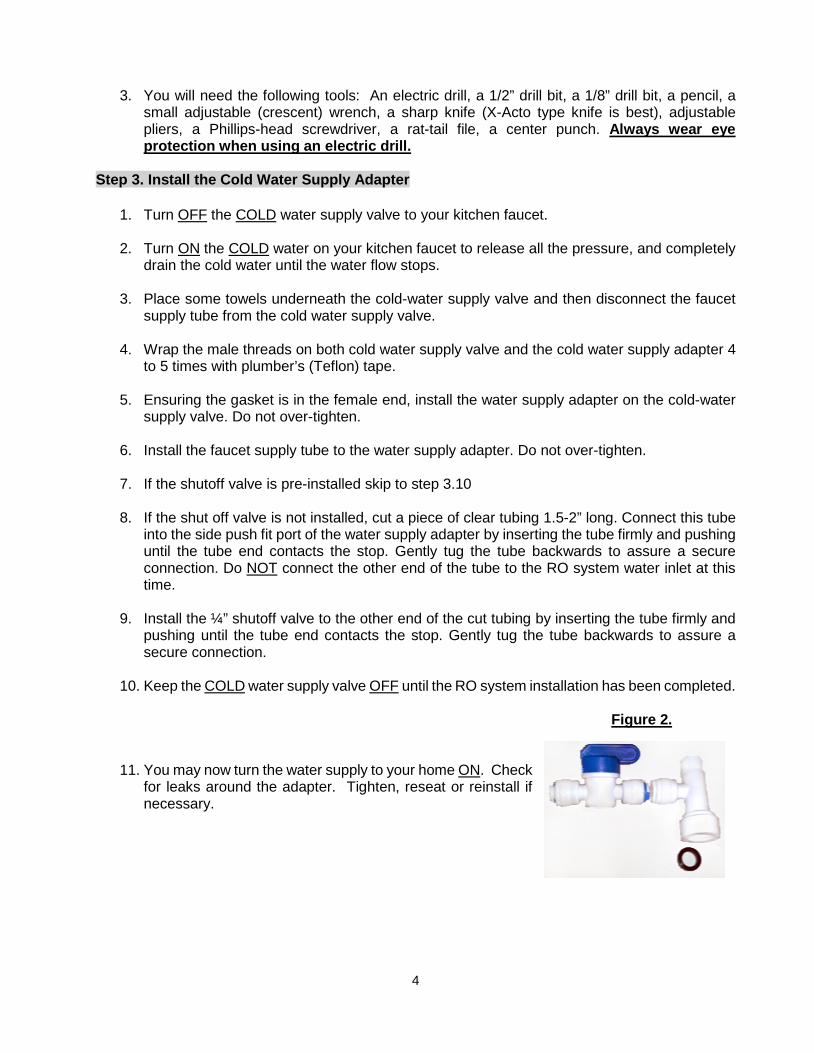
Figure 2.
11. You may now turn the water supply to your home ON. Check for leaks around the adapter. Tighten, reseat or reinstall if necessary.
5
Step 4. Install the Sink Faucet Tools required for this step: An electric drill, a 1/2” carbide bit, a small adjustable wrench, a center punch, a pencil, a rat-tail file.
Your dealer will be able to supply a variety of designer faucets and finishes to suit your particular installation, if you wish. Included with your system is a premier quality chrome faucet that is compatible to most kitchen installations.
1. Examine the sink. If it has an existing hole for mounting a faucet, skip to Step 4.6. 2. Locate and mark the spot you wish to install the faucet. Make sure it does not interfere with
operation of the main faucet and that there is clearance for plumbing and mounting hardware directly below it under the sink or countertop. If you have a stainless sink, go to Step 4.5
3. If you have a concrete sink with a thickness of less than 1”, the faucet can be mounted directly
to sink. If the thickness exceeds 1”, the faucet must be mounted directly on the countertop or a faucet with an extended shank must be used. Tool substitution: Use a 1/2” masonry bit to drill the concrete sink.
4. If you have a porcelain enamel or ceramic sink, it is strongly recommended that a
professional install the faucet to avoid chipping and damaging the sink finish.
5. Mark the spot chosen for the faucet hole with the pencil. Use the center punch to slightly indent the spot (the center punch is unnecessary for concrete sinks). Use the 1/8” bit and drill the hole. Use the ½” bit to enlarge the hole. Use the rat-tail file to smooth any burrs or rough edges on the hole.
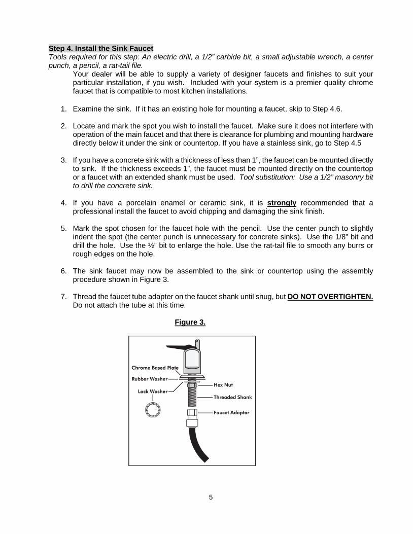
6. The sink faucet may now be assembled to the sink or countertop using the assembly
procedure shown in Figure 3. 7. Thread the faucet tube adapter on the faucet shank until snug, but DO NOT OVERTIGHTEN.
Do not attach the tube at this time.
Figure 3.
6
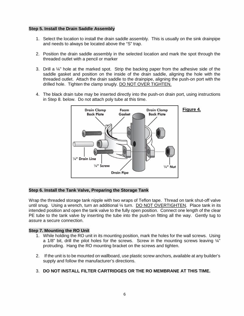
Step 5. Install the Drain Saddle Assembly
1. Select the location to install the drain saddle assembly. This is usually on the sink drainpipe and needs to always be located above the “S” trap.
2. Position the drain saddle assembly in the selected location and mark the spot through the
threaded outlet with a pencil or marker
3. Drill a ¼” hole at the marked spot. Strip the backing paper from the adhesive side of the saddle gasket and position on the inside of the drain saddle, aligning the hole with the threaded outlet. Attach the drain saddle to the drainpipe, aligning the push-on port with the drilled hole. Tighten the clamp snugly. DO NOT OVER TIGHTEN.
4. The black drain tube may be inserted directly into the push-on drain port, using instructions
in Step 8. below. Do not attach poly tube at this time.
Figure 4. Step 6. Install the Tank Valve, Preparing the Storage Tank Wrap the threaded storage tank nipple with two wraps of Teflon tape. Thread on tank shut-off valve until snug. Using a wrench, turn an additional ¼ turn. DO NOT OVERTIGHTEN. Place tank in its intended position and open the tank valve to the fully open position. Connect one length of the clear PE tube to the tank valve by inserting the tube into the push-on fitting all the way. Gently tug to assure a secure connection. Step 7. Mounting the RO Unit
1. While holding the RO unit in its mounting position, mark the holes for the wall screws. Using a 1/8” bit, drill the pilot holes for the screws. Screw in the mounting screws leaving ¼” protruding. Hang the RO mounting bracket on the screws and tighten.
2. If the unit is to be mounted on wallboard, use plastic screw anchors, available at any builder’s
supply and follow the manufacturer’s directions.
3. DO NOT INSTALL FILTER CARTRIDGES OR THE RO MEMBRANE AT THIS TIME.

7
Step 6. Connect the System Tubing
1. Insert the ¼” clear tubing into the other end of the ¼” Cold water shut off valve you just
installed. Measure and cut the tubing to allow for easy access to the RO unit. Connect the tubing to the first filter housing water inlet push-on fitting on the left side (marked “water inlet”)
2. Install the pressure reducing valve on the line between the shutoff valve and the first filter. Make sure the arrow is pointing in the direction of flow. (shutoff valve RO)
3. Connect the black ¼” tube (marked “to drain”) to the Drain Saddle push-on connection (your
black drain tube is pre-attached to your RO). Please note that the drain line flow restrictor has been installed INSIDE the black drain tube at the waste elbow, on the membrane housing.
4. Place the storage tank in the location you have chosen for it. Using the clear 3/8” tube connect the system fitting marked “to tank” to the tank valve. Connect the 3/8” tube attached to the faucet to the system fitting marked “to faucet”. If the tubing is not pre-attached to the faucet, cut the 3/8” clear tubing to the desired length and attach the tube to the fitting at the base of the faucet shank to the fitting marked “to faucet” on the RO unit.
5. You may find that your unit does not have labels attached to indicate the water line and drain
line connections. The photos below are labelled with the correct locations for the water and drain connections.
Cold water inlet
Drain
To Faucet To Tank
! DO NOT USE ANY WATER FROM THE SYSTEM UNTIL THE NEXT STEP IS COMPLETE.
8
Step 7. Starting Up the VectatwistTM Filtration System
1. Turn on the water supply saddle valve and check all connections for leaks. Do not proceed further until any leaks are fixed.
2. Install the Leak Stop as per addendum directions. 3. With the faucet open, let the system operate for about 10 minutes. Close the tank valve and
the faucet. Check for leaks again and fix if necessary. 4. Open the storage tank valve. The system is now operating and filling the storage tank. Allow
the tank to fill completely and the system to automatically shut itself off. This step may take as much as 30 minutes or more.
5. Once the system shuts off, open the faucet and let the entire tank drain completely. You may see dark carbon dust briefly flush from the carbon cartridge – this is harmless and normal for the first flow of water through the cartridge. Allow the system to re-fill the tank. Once completed, your system is ready for use.
Section 3: Operation and Maintenance
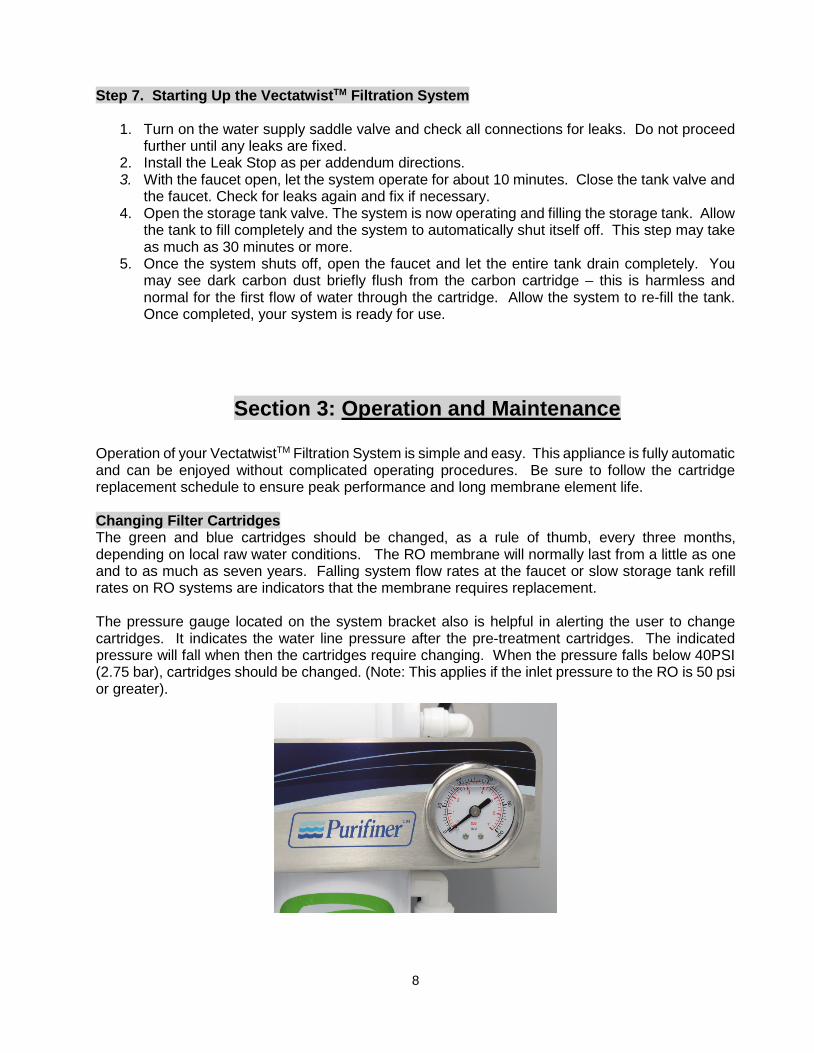
Operation of your VectatwistTM Filtration System is simple and easy. This appliance is fully automatic and can be enjoyed without complicated operating procedures. Be sure to follow the cartridge replacement schedule to ensure peak performance and long membrane element life. Changing Filter Cartridges The green and blue cartridges should be changed, as a rule of thumb, every three months, depending on local raw water conditions. The RO membrane will normally last from a little as one and to as much as seven years. Falling system flow rates at the faucet or slow storage tank refill rates on RO systems are indicators that the membrane requires replacement. The pressure gauge located on the system bracket also is helpful in alerting the user to change cartridges. It indicates the water line pressure after the pre-treatment cartridges. The indicated pressure will fall when then the cartridges require changing. When the pressure falls below 40PSI (2.75 bar), cartridges should be changed. (Note: This applies if the inlet pressure to the RO is 50 psi or greater).
9
Membrane elements require changing much less frequently than the filter cartridges and only when failure is indicated. This should be done when water production begins to noticeably fall or TDS readings in the product water begin to rise. Total Dissolved Solids may be measured by a water professional or by use of a simple hand-held TDS meter. These are available from your dealer or from Waterite’s Online Store at www.waterite.com. Soft water free from iron is ideal for long membrane life. Hardness, iron, chlorine and infrequently changed filter cartridges are the membrane’s greatest enemies. Filter cartridges may be changed with the saddle valve ON. However, a small amount of water may seep from the cartridge socket momentarily upon removal. To avoid this leakage, simply turn the saddle valve OFF when changing cartridges.
1. Close the cold-water supply saddle valve and close the tank valve. Open the faucet until the flow of water stops, and then close. Grasping the cartridge to be removed, twist ¼ turn COUNTER-CLOCKWISE. The cartridge will disengage and can be easily removed by pulling it out of the socket. Repeat for each cartridge to be changed.
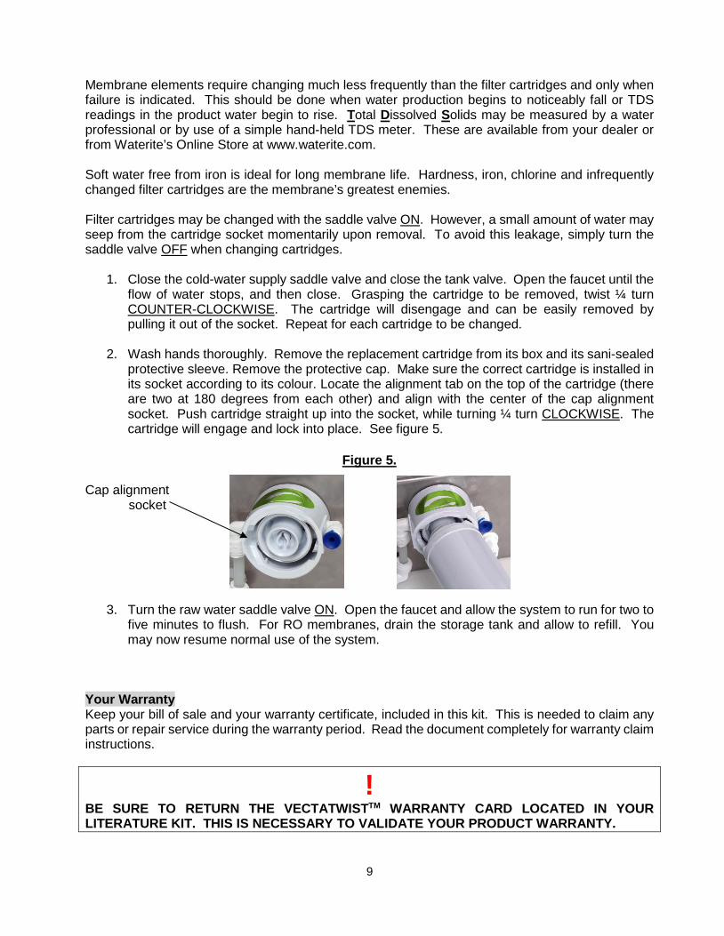
2. Wash hands thoroughly. Remove the replacement cartridge from its box and its sani-sealed
protective sleeve. Remove the protective cap. Make sure the correct cartridge is installed in its socket according to its colour. Locate the alignment tab on the top of the cartridge (there are two at 180 degrees from each other) and align with the center of the cap alignment socket. Push cartridge straight up into the socket, while turning ¼ turn CLOCKWISE. The cartridge will engage and lock into place. See figure 5.
Figure 5.
Cap alignment socket
3. Turn the raw water saddle valve ON. Open the faucet and allow the system to run for two to five minutes to flush. For RO membranes, drain the storage tank and allow to refill. You may now resume normal use of the system.
Your Warranty Keep your bill of sale and your warranty certificate, included in this kit. This is needed to claim any parts or repair service during the warranty period. Read the document completely for warranty claim instructions.
! BE SURE TO RETURN THE VECTATWISTTM WARRANTY CARD LOCATED IN YOUR LITERATURE KIT. THIS IS NECESSARY TO VALIDATE YOUR PRODUCT WARRANTY.
10
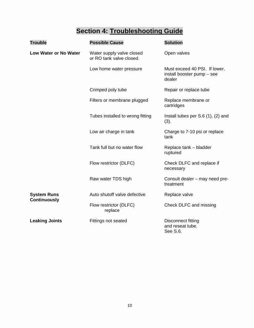
Section 4: Troubleshooting Guide Trouble Possible Cause Solution Low Water or No Water Water supply valve closed Open valves or RO tank valve closed.
Low home water pressure Must exceed 40 PSI. If lower, install booster pump – see dealer
Crimped poly tube Repair or replace tube Filters or membrane plugged Replace membrane or
cartridges Tubes installed to wrong fitting Install tubes per S.6 (1), (2) and
(3). Low air charge in tank Charge to 7-10 psi or replace
tank Tank full but no water flow Replace tank – bladder
ruptured Flow restrictor (DLFC) Check DLFC and replace if
necessary Raw water TDS high Consult dealer – may need pre-
treatment System Runs Auto shutoff valve defective Replace valve Continuously
Flow restrictor (DLFC) Check DLFC and missing replace
Leaking Joints Fittings not seated Disconnect fitting
and reseat tube. See S.6.

11
DRINKING WATER SYSTEM COMMON PARTS LIST
Calculating your RO System’s Daily Output The Pressure and temperature chart below will help you determine what daily output you can expect from your VectatwistTM RO System. Your RO system is rated to produce 400 US gallons per day, or approximately 1515 litres per day. Membranes are nominally rated at about 77°F (23°C) and 65 PSI (4.5 bar). By measuring your household pressure and inlet water temperature, you may calculate the expected production of your RO system in your home. Keep in mind that RO membrane output normally decreases with age, up to about 10% in the first year. Example: 58°F (13°C) and 50 PSI (3.4 bar) measured in your home at the RO inlet. (From the chart below) .5094 X 400 gallons = 203.8 gallons (771 litres) per day. 203.8 gallons/24 hours = 8.5 gallons (32.2 litres) per hour production rate
VISIT THE WATERITE WEBSITE FOR INFORMATION, CONSUMER ONLINE REPLACEMENT PARTS AND PRODUCT
UPDATES AT: www.waterite.com
DESCRIPTION PART NUMBER Auto shut-off valve (RO) ROS002
Pre-filter PP Sediment Cartridge (Blue) VTSED05 Pre-filter CBC Carbon Cartridge (Green) VTCBC10
400 GPD RO Membrane BME3013SXL Cold Water Line Adapter ROTF3814
Faucet F9C ¼” push-on tee (used for refrigerator hook-up) A4TU4
¼” shut off valve push fit A4HVU4 Drain Line Flow Control 750 ml/min (DLFC) 069-E
¼” Clear Tubing (100ft) 3634-100 3/8” Clear Tubing (100ft) 3636-100

12

13
THIS PAGE HAS BEEN LEFT BLANK INTENTIONALLY
REGISTER YOUR PRODUCT ONLINE AT WATERITE.COM OR FILL OUT THE INCLUDED PRE-PAID, SELF ADDRESSED POSTCARD.

14
THIS PAGE HAS BEEN LEFT BLANK INTENTIONALLY
REGISTER YOUR PRODUCT ONLINE AT WATERITE.COM OR FILL OUT THE
INCLUDED PRE-PAID, SELF ADDRESSED POSTCARD.

15
Purifiner A Division of WATERITE, INC.
Winnipeg, Manitoba Canada
www.purifiner.com www.waterite.com