installation and operation manua · installation and operation manual document number: 570-4010...
TRANSCRIPT
INSTALLATION ANDOPERATION MANUAL
Document Number: 570-4010 Revision -
24 Bit Address ProgrammingDongle
Model: DGL-1
Artex Aircraft Supplies, Inc.14405 Keil Road NE
Aurora, Oregon 97002 USATel (503) 678-7929, Fax (503) 678-7930
E-mail [email protected]
ARTEXAIRCRAFTSUPPLIES,INC.REGISTEREDTOISO9001
ANDAS9100FILENUMBERA10217
Table of Contents
4 System Requirements
6 Installation
12 Aircraft Address
14 Operation
15 Test
16 Installation Finalization
18 Scheduled Maintenance
19 Trouble Shooting
20 Appendix A
3
DGL-1 Manual 570-4010
System RequirementsEmergency Locator Transmitter
Artex ELT with software version V133M, V134B or V135C. TheELT software version is displayed on the ELT product label.
The Artex ELT must be programmed with a 24 Bit Address LongMessage Protocol. In general, an ELT programmed with 24 BitAddress Long Message Protocol will have a 999 extension on thepart number. Example: 453-0000 (999). The 999 extension isapplied at factory to indicate the 24 Bit Address Protocol. Subsequent field programming may have changed the protocol. To verify the protocol type, use the Sarsat Beacon Test Set, ARGModel 5410 or equivalent.
Aircraft
28 volt DC power source capable of providing 25mA
Test Equipment
406 Mhz uplink receiver. Artex recommends the Sarsat BeaconTest Set, Model ARG 5410, which is available for rent, or purchase from Artex.
VHF communication radio tuned to 121.5 Mhz.
Tools:
Standard phillips #2 screw driver
RTV 162 or equivalent silicone sealant
Crimp Tool, Molex 11-01-0008 or equivalent
4
DGL-1 Manual 570-4010
Extraction Tool, Molex 11-03-0002 or equivalent
Heat gun for Raychem wire splice
Regulatory Requirements
Because of the critical nature of an ELT and dongle, it is importantthat the installation be performed according to the followinginstructions. Installation of the ELT and dongle requiresexperience with avionics and only licensed technicians shouldinstall this system.
In addition to the procedures outlined in this manual, the installermust adhere to the guidelines established in FAA-Advisory Circular 43.13-2A, Chapters 1 through 3, 11 and 13 (Acceptable Methods,Techniques and Practices Aircraft Alterations).
By signing either the aircraft logbooks or the FAA Form 337, youare stating that the installation has been performed in accordancewith the current FARs and with the steps and procedures outlinedin this manual.
5
DGL-1 Manual 570-4010
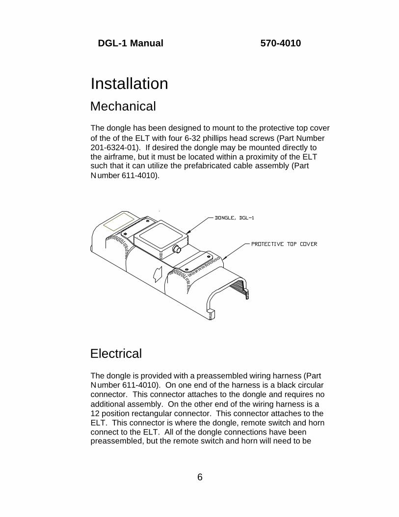
InstallationMechanical
The dongle has been designed to mount to the protective top cover of the of the ELT with four 6-32 phillips head screws (Part Number201-6324-01). If desired the dongle may be mounted directly tothe airframe, but it must be located within a proximity of the ELTsuch that it can utilize the prefabricated cable assembly (PartNumber 611-4010).
Electrical
The dongle is provided with a preassembled wiring harness (PartNumber 611-4010). On one end of the harness is a black circularconnector. This connector attaches to the dongle and requires noadditional assembly. On the other end of the wiring harness is a12 position rectangular connector. This connector attaches to theELT. This connector is where the dongle, remote switch and hornconnect to the ELT. All of the dongle connections have beenpreassembled, but the remote switch and horn will need to be
6
DGL-1 Manual 570-4010
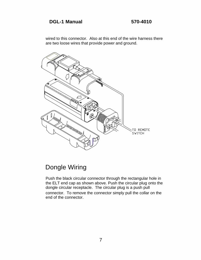
wired to this connector. Also at this end of the wire harness thereare two loose wires that provide power and ground.
Dongle Wiring
Push the black circular connector through the rectangular hole inthe ELT end cap as shown above. Push the circular plug onto thedongle circular receptacle. The circular plug is a push pullconnector. To remove the connector simply pull the collar on theend of the connector.
7
DGL-1 Manual 570-4010
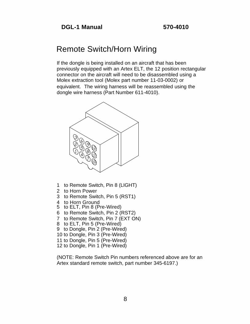
Remote Switch/Horn Wiring
If the dongle is being installed on an aircraft that has beenpreviously equipped with an Artex ELT, the 12 position rectangularconnector on the aircraft will need to be disassembled using aMolex extraction tool (Molex part number 11-03-0002) orequivalent. The wiring harness will be reassembled using thedongle wire harness (Part Number 611-4010).
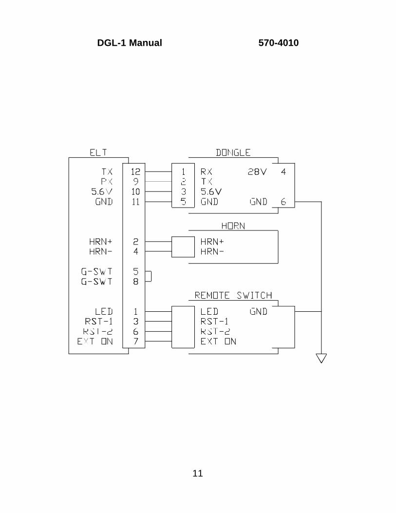
1 to Remote Switch, Pin 8 (LIGHT)2 to Horn Power3 to Remote Switch, Pin 5 (RST1)4 to Horn Ground5 to ELT, Pin 8 (Pre-Wired)6 to Remote Switch, Pin 2 (RST2)7 to Remote Switch, Pin 7 (EXT ON)8 to ELT, Pin 5 (Pre-Wired)9 to Dongle, Pin 2 (Pre-Wired)10 to Dongle, Pin 3 (Pre-Wired)11 to Dongle, Pin 5 (Pre-Wired)12 to Dongle, Pin 1 (Pre-Wired)
(NOTE: Remote Switch Pin numbers referenced above are for anArtex standard remote switch, part number 345-6197.)
8
DGL-1 Manual 570-4010
Pin 11 is the grounding point for the ELT. The ELT installation and operation manual indicates that pin 11 is connected to aircraftground. When using the dongle pin 11 is preassembled in theprovided wire harness, and the ELT ground will be providedthrough the dongle. The system grounding is further defined in the Ground Wiring section of this manual.
The wires coming from the horn and the remote switch will need tobe terminated with the male terminal pins provided (Part Number151-6627). Strip about .150 in. of insulation, and tin the ends of the wires. Use a Molex crimp tool (Molex Tool # 11-01-0008) orequivalent to install the provided terminal pins. Insert theterminated wires into their applicable location in the rectangular 12position connector.
Refer to the applicable ELT installation and operation manual foraddition wiring information.
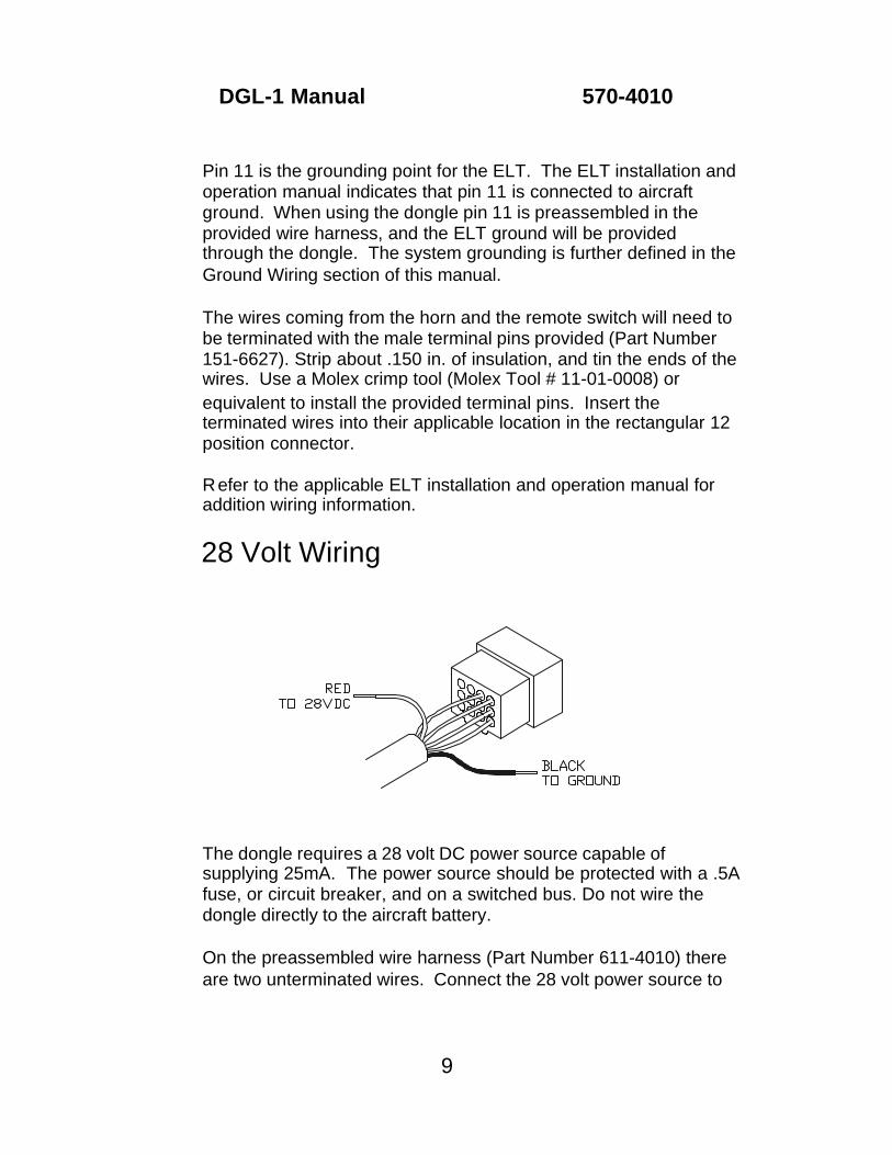
28 Volt Wiring
The dongle requires a 28 volt DC power source capable ofsupplying 25mA. The power source should be protected with a .5A fuse, or circuit breaker, and on a switched bus. Do not wire thedongle directly to the aircraft battery.
On the preassembled wire harness (Part Number 611-4010) thereare two unterminated wires. Connect the 28 volt power source to
9
DGL-1 Manual 570-4010
the red wire. A Raychem solder sleeve splice (Raychem #D-1744-01) is provided for this connection. Contact Raychem forspecific instructions on the use of this splice. Alternate splicesmay be used if installed in accordance with FAA AC 43.13.1A,Section 445, Splices in Electrical Wire.
Ground Wiring
INSTALLING ELT AND DONGLE. For new ELT and dongleinstallations splice the unterminated black wire on thepreassembled wire harness to an aircraft ground point near theELT. A Raychem solder sleeve splice (Raychem # D-1744-01) isprovided for this connection. Contact Raychem for specificinstructions on the use of this splice. Alternate splices may beused if installed in accordance with FAA AC 43.13.1A, Section445, Splices in Electrical Wire.
The ELT installation and operation manual will indicate that theremote switch ground is to be connected to pin 11 of the ELT. When installing the dongle pin 11 will not be available for remoteswitch grounding. It is recommended that either the ground splice, or the aircraft grounding point mentioned in the previous paragraph be used as a remote switch ground.
INSTALLING DONGLE TO PREVIOUSLY INSTALLED ELT. After disassembling and reassembling the 12 position rectangular ELTconnector as described in the Remote Switch/Horn Wiring sectionof this manual, there will be an unterminated ground wire from theremote switch. Ground this wire as described in the paragraphabove.
10
DGL-1 Manual 570-4010
11
DGL-1 Manual 570-4010
Aircraft AddressICAO 24 Bit Address
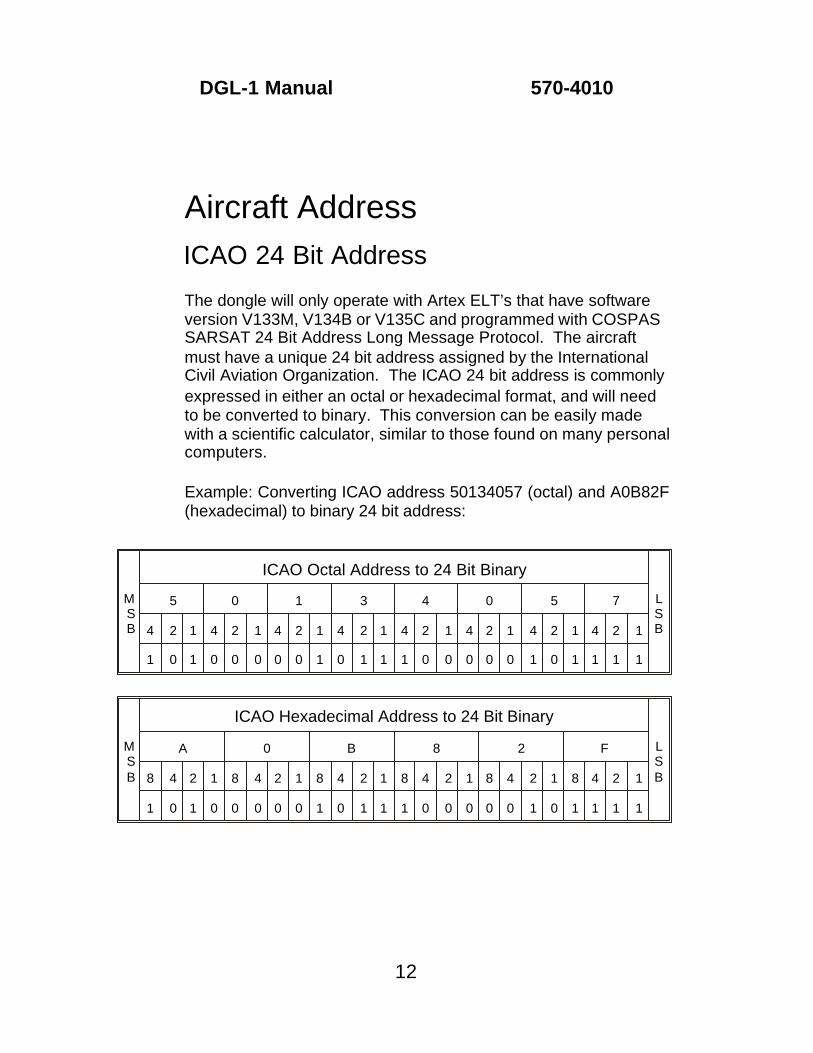
The dongle will only operate with Artex ELT’s that have softwareversion V133M, V134B or V135C and programmed with COSPASSARSAT 24 Bit Address Long Message Protocol. The aircraftmust have a unique 24 bit address assigned by the InternationalCivil Aviation Organization. The ICAO 24 bit address is commonlyexpressed in either an octal or hexadecimal format, and will needto be converted to binary. This conversion can be easily madewith a scientific calculator, similar to those found on many personal computers.
Example: Converting ICAO address 50134057 (octal) and A0B82F (hexadecimal) to binary 24 bit address:
12
DGL-1 Manual 570-4010
MSB
ICAO Hexadecimal Address to 24 Bit Binary
LSB
A 0 B 8 2 F
8 4 2 1 8 4 2 1 8 4 2 1 8 4 2 1 8 4 2 1 8 4 2 1
1 0 1 0 0 0 0 0 1 0 1 1 1 0 0 0 0 0 1 0 1 1 1 1
MSB
ICAO Octal Address to 24 Bit Binary
LSB
5 0 1 3 4 0 5 7
4 2 1 4 2 1 4 2 1 4 2 1 4 2 1 4 2 1 4 2 1 4 2 1
1 0 1 0 0 0 0 0 1 0 1 1 1 0 0 0 0 0 1 0 1 1 1 1
13
DGL-1 Manual 570-4010
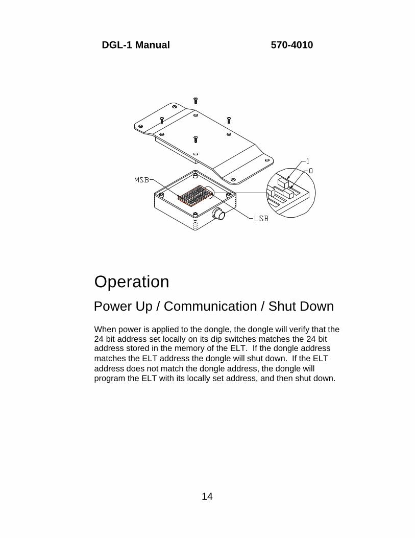
Setting 24 Bit Address
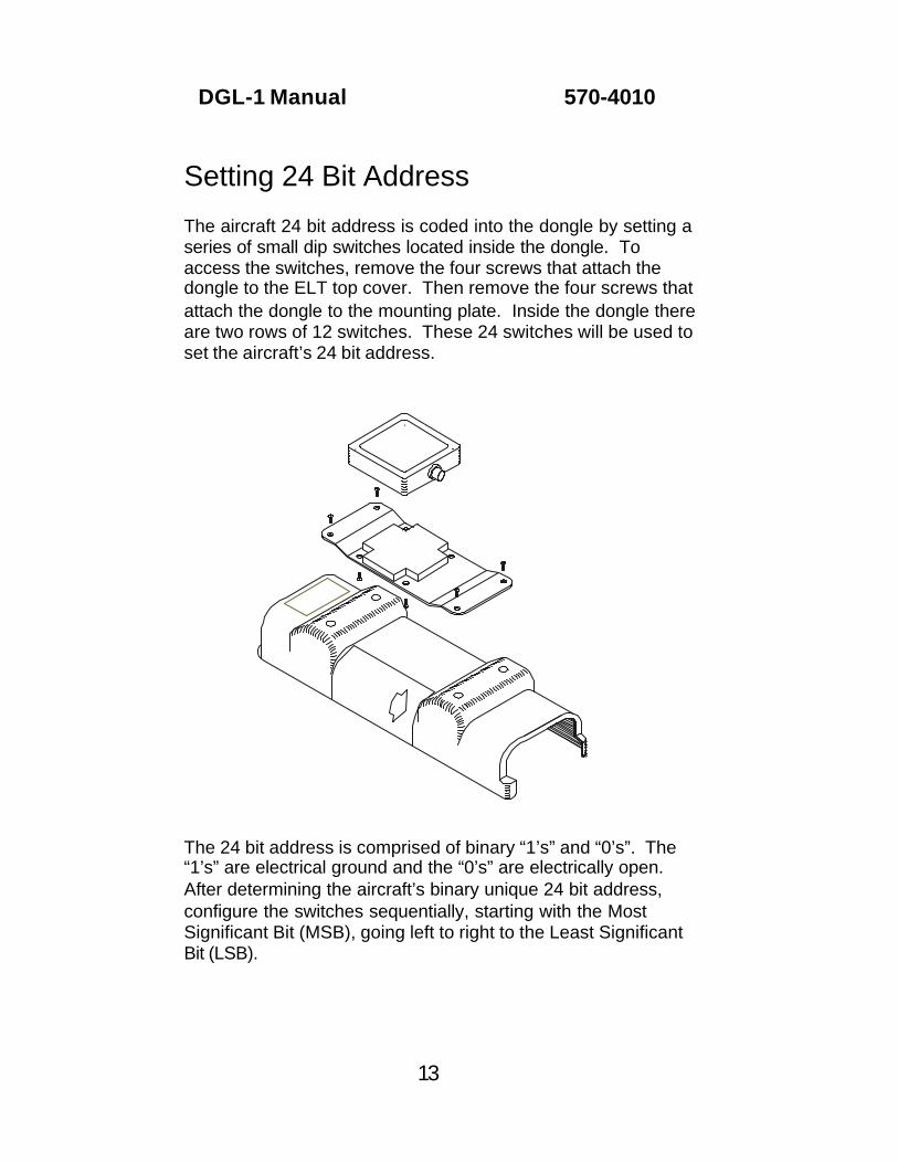
The aircraft 24 bit address is coded into the dongle by setting aseries of small dip switches located inside the dongle. Toaccess the switches, remove the four screws that attach thedongle to the ELT top cover. Then remove the four screws thatattach the dongle to the mounting plate. Inside the dongle there are two rows of 12 switches. These 24 switches will be used toset the aircraft’s 24 bit address.
The 24 bit address is comprised of binary “1’s” and “0’s”. The“1’s” are electrical ground and the “0’s” are electrically open. After determining the aircraft’s binary unique 24 bit address,configure the switches sequentially, starting with the MostSignificant Bit (MSB), going left to right to the Least SignificantBit (LSB).
OperationPower Up / Communication / Shut Down
When power is applied to the dongle, the dongle will verify that the24 bit address set locally on its dip switches matches the 24 bitaddress stored in the memory of the ELT. If the dongle addressmatches the ELT address the dongle will shut down. If the ELT address does not match the dongle address, the dongle willprogram the ELT with its locally set address, and then shut down.
14
DGL-1 Manual 570-4010
Failure Mode
The dongle will attempt to synchronize its locally set 24 bit address with the ELT for 2 minutes. If the dongle is unable synchronize itslocally set 24 bit address with the ELT it will cause the ELT remoteswitch and local annunciator to continuously flash. For furtherinformation see the Test and Trouble Shooting sections of thismanual.
TestSetup
After the dongle has been installed, setup the test environment asfollows:
• Ensure bus power to the dongle is off.
• Ensure all circuit breakers for the ELT system have been reset.
• Ensure the ELT local switch is in the OFF position, and the ELT isnot transmitting.
• Ensure the ELT remote switch is in the ARM position.
• Attach a 406MHz uplink receiver to the 406MHz output of theELT. Artex recommends the Sarsat Beacon Test Set, Model ARG 5410. WARNING: When using the ARG 5410, ensure there is30db of attenuation between ARG 5410 and the ELT. Failure toattenuate the 406MHz signal will damage the ARG 5410.
Testing
• Apply bus power to the ELT/ dongle system and wait a minimumof 2 minutes. Once 2 minutes has elapsed, verify that neither thelocal ELT, nor remote switch annunciator are flashing. If the
15
DGL-1 Manual 570-4010
annunciators are flashing, refer to the troubleshooting section ofthis manual.
• Turn on the uplink receiver. Refer to the uplink receiver operationmanual for further information on the use of this test equipment.
• Use the local ELT switch to activate the ELT. Allow the ELT totransmit until the uplink receiver has received a 406 transmission,then deactivate the ELT.
• When the ELT is deactivated it will go through a self test. TheELT annunciator will flash five times to indicate a navigation datafailure. This is because the dongle does not support the navfunction of the ELT. The nav function of the ELT requires the useof the Artex Nav Interface Unit. If the ELT flashes any otherfailure codes, refer to the applicable ELT manual to troubleshootthe problem.
• Use the uplink receiver to verify that the ELT transmitted thedongle’s locally set 24 bit address. Refer to the uplink receiveroperation manual for further information on the use of this testequipment.
Installation FinalizationELT Identification
After the functional test has been completed, the uplink receivershould have a 15 digit hex identification code stored from theELT’s 406MHz transmission. This 15 digit code comprises theELT country code, 24bit address, beacon certification number, and other information. Label the ELT with this 15 digit code. On newbeacons there will be a blank area on the side of the ELT productlable where the code can be written. On older units the new labelwill have to be applied over the old 15 digit code.
16
DGL-1 Manual 570-4010
Connector Sealing
Once all tests have been satisfactorily completed, and all harnessconnections have been verified to be correct, the rectangular 12position ELT connector should be sealed to prevent moisture fromgetting to the contact pins. This can be done by applying anelectronic grade, non-corrosive RTV around the wires entering therear of the connector. Artex recommends GE RTV 162.
Log Book / Form 337
By signing either the aircraft logbooks, or the FAA Form 337, youare stating that the installation has been performed in accordancewith current FAR’s and steps and procedures outlined in thismanual.
17
DGL-1 Manual 570-4010
Scheduled MaintenanceInspection Schedule
The dongle is considered part of the ELT system and as part of the system should be on a yearly inspection schedule, or inspectedwhenever the ELT is inspected.
Inspection and Test
The inspection described in this manual is limited to the dongle. For detailed information about the inspection of the ELT systemrefer to the applicable ELT installation and operation manual.
• Remove the black circular connector from the dongle, and inspectboth the plug and receptacle for corrosion.
• Remove the four screws that attach the dongle to the top cover. Then, remove the four screws that attach the dongle to themounting plate. See the Aircraft Address section of this manualfor an illustration.
• Inspect the physical integrity of the case, gasket and dip switchesfor wear, contamination and corrosion.
• Change the position of the Most Significant Bit (MSB) dip switch,and reconnect the black circular connector.
• Test the ELT in accordance with the Test section of this manualand the applicable ELT installation and operation manual.
• Verify that the ELT 15 digit hex identification code, and 24 bitaddress has changed as a result of changing the position of theMSB dip switch. The ELT 15 digit hex identification code shouldbe recorded on the ELT product label.
18
DGL-1 Manual 570-4010
• Change the position of the MSB dip switch back to its originalposition, and reassemble the dongle.
• Test the dongle again, and verify that the ELT 15 digit hexidentification code, and 24 bit address have changed back to theoriginal configuration. The ELT 15 digit hex identification codeshould match the code recorded on the ELT product label.
TroubleshootingFAILURE:
ELT and Remote Switch Annunciators flash continuously whenELT is not transmitting.
CAUSE:
The dongle will attempt to synchronize its locally set 24 bit address with the ELT for 2 minutes. If the dongle is unable synchronize itslocally set 24 bit address with the ELT it will cause the ELT remoteswitch and local annunciator to continuously flash.
If your ELT is not programmed with a 24 Bit Address protocol youwill receive this failure indication. Use an uplink receiver to verifythat the ELT protocol has been programmed with a 24 Bit Addressprotocol. Refer to the uplink receiver operation manual for furtherinformation on the use of this test equipment.
If the ELT has not been programmed with a 24 Bit Addressprotocol, contact the Artex Service Department for reprogramminginformation. If ELT has been programmed with a 24 Bit Addressprotocol, contact the Artex Service Department for furthertroubleshooting assistance.
CAUSE:
The communication between the ELT and dongle is made throughthe transmit and receive lines on pins 1 and 2 of the dongle. If
19
DGL-1 Manual 570-4010
these lines are open, or shorted, the dongle will not synchronize its locally set 24 bit address with the ELT. This will cause the ELTremote switch and local annunciator to continuously flash.
Verify continuity between pin 1 of the circular connector and pin 12 of the rectangular connector. Verify continuity between pin 2 of the circular connector and pin 9 of the rectangular connector. Finallyverify that these connections are not shorted to any other pins. Ifthe wire harness is good, contact the Artex Service Department for further troubleshooting assistance.
20
DGL-1 Manual 570-4010
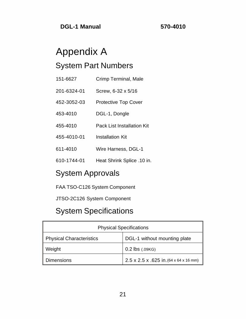
Appendix ASystem Part Numbers
151-6627 Crimp Terminal, Male
201-6324-01 Screw, 6-32 x 5/16
452-3052-03 Protective Top Cover
453-4010 DGL-1, Dongle
455-4010 Pack List Installation Kit
455-4010-01 Installation Kit
611-4010 Wire Harness, DGL-1
610-1744-01 Heat Shrink Splice .10 in.
System Approvals
FAA TSO-C126 System Component
JTSO-2C126 System Component
System Specifications
Physical Specifications
Physical Characteristics DGL-1 without mounting plate
Weight 0.2 lbs (.09KG)
Dimensions 2.5 x 2.5 x .625 in. (64 x 64 x 16 mm)
21
DGL-1 Manual 570-4010
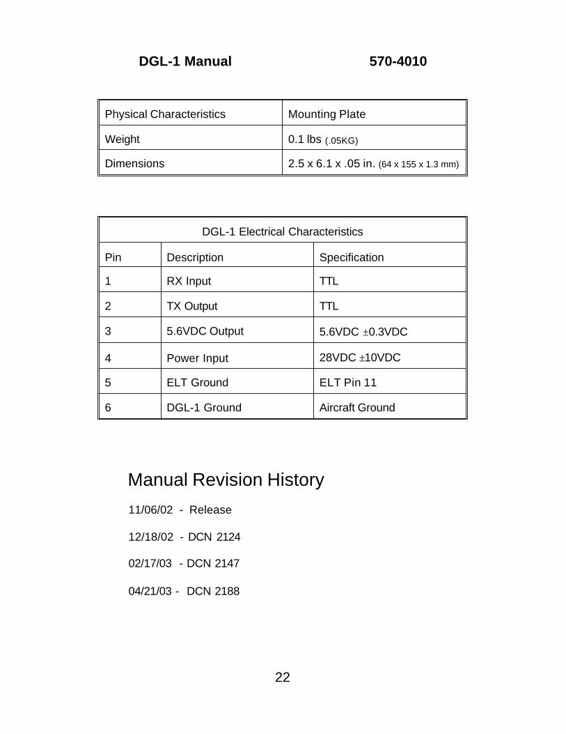
Physical Characteristics Mounting Plate
Weight 0.1 lbs (.05KG)
Dimensions 2.5 x 6.1 x .05 in. (64 x 155 x 1.3 mm)
DGL-1 Electrical Characteristics
Pin Description Specification
1 RX Input TTL
2 TX Output TTL
3 5.6VDC Output 5.6VDC ±0.3VDC
4 Power Input 28VDC ±10VDC
5 ELT Ground ELT Pin 11
6 DGL-1 Ground Aircraft Ground
Manual Revision History
11/06/02 - Release
12/18/02 - DCN 2124
02/17/03 - DCN 2147
04/21/03 - DCN 2188
22
DGL-1 Manual 570-4010