installation and oper - ating manual
TRANSCRIPT
Air humidification, dehumidification and evaporative cooling
CONDAIR AXReverse osmosis system
INSTALLATION AND OPER-ATING MANUALCondair AX reverse osmosis system 01/01/2021
2021
0101
EN
210
1

Proprietary noticeThis document and the information contained therein are the property of Condair GmbH. Neither this document (including extracts thereof), nor the information contained herein shall be reproduced, used, or disclosed to others without the manufacturer’s written authorisation. Non-compliance with this is punishable by law and will result in compensation for damages.
LiabilityCondair GmbH does not accept any liability due to incorrect installation or operation of the equipment or due to use of parts/components/equipment that are not authorised by Condair AG.
Copyright noticeCopyright 2015, Condair GmbH, all rights reserved, subject to technical changes
Thank you for choosing Condair
Installation date (DD/MM/YYYY):
Commissioning date (DD/MM/YYYY):
Site:
Model:
Serial number:
3
Contents
1 General safety instructions 51.1 Explanations of symbols and instructions 51.2 Operator obligations 51.3 Personnel obligations 61.4 Training of personnel 61.5 Intended use 61.6 Hazards when handling the equipment 61.7 Protective devices and safety measures to avert hazards 71.7.1 Protective devices 71.7.2 Informational safety measures 71.8 Safety instructions for maintenance work 81.9 Disposal of system parts and operating materials 81.10 Unauthorisedmodificationandreplacementparts 81.11 Warranty and liability 81.12 Safety instructions for storage 9
2 Principles of reverse osmosis systems 102.1 Calculation equations 102.2 Temperature dependency of the permeate output 102.3 Conductivityoffirstpermeate 11
3 Transport and storage 123.1 Transport to the customer 123.2 Storage at the customer’s premises 123.1 Transport to the installation site 12
4 Technical data / Product description 134.1 Technical data 134.2 Application limits 144.3 Product description 154.3.1 Layout 154.3.2 Function 16
5 Installation and assembly 175.1 Installation 175.1.1 Requirements of the installation site 175.1.2 Installation of the system 175.2 Water connections 185.2.1 Requiredqualificationofassemblypersonnel 185.2.2 Establishing the water connections 185.3 Electrical connection 195.3.1 Requiredqualificationofassemblypersonnel 195.3.2 Establishing the electrical connections 195.3.3 Connection of external signals from and messages to BMS 195.3.4 Cable list 195.3.5 Terminal connection table 20
Contents
4
6 Commissioning and decommissioning 216.1 Commissioning 216.1.1 Qualificationofcommissioningpersonnel 216.1.2 Flushing out the preservative 216.1.3 Setting up automatic mode 216.1.4 Configuringpermeateoutputandyield 216.1.5 Configuringpermeateoutletpressure 226.2 Decommissioning 226.3 Possible water treatment layout 22
7 Control panel 237.1 Control and display elements 237.2 User menu 247.2.1 Structure and content 247.2.2 Entries/changes in the user menu 267.3 Scrolling display 277.3.1 Uninterrupted operating sequence 277.3.2 Interrupted operating sequence 287.4 Parameters 30
8 Fault elimination 328.1 General information 328.1.1 Fault reporting to the manufacturer 328.1.2 Fault indication and reset 328.2 Fault analysis and elimination 328.3 Flushing the concentrate 34
9 Inspection and maintenance 359.1 Inspection and maintenance work 359.1.1 Safety instructions 359.1.2 General information 359.2 Logging the operating parameters 369.2.1 List of parameters to be logged 369.2.2 Operations log for reverse osmosis systems 379.3 Maintenance 389.3.1 Maintenance plan for reverse osmosis systems 38
10. Appendix 3910.1 Assembly layout (schematic) 3910.2 P&I diagram 4010.3 Dimensions of AX 02 4110.4 Dimensions of AX 05, 12 and 20 4210.5 Dimensions of AX 30 and 50 43
Contents
5
1. General safety instructions
1.1 Explanations of symbols and instructions This operating manual contains important information on the safe operation of the system.
This operating manual, in particular the chapter “Safety instructions” must be observed by all persons working on the system. This applies to the installation company as well as to the system operator. Moreover, the special rules and guidelines for accident prevention that apply to the location of use must also be followed.
In this operating manual, the following symbols are used to indicate hazards for persons and to ensure proper handling of the equipment:
1.2 Operator obligations The operator undertakes to only allow persons to work on the system who are familiar with the fundamental regulations on occupational safety and accident pre-
vention and have been instructed in the handling of the system, who have read and understood the chapter on safety and the warnings in this operating
manual and who have acknowledged this with their signature and whose safe working practices are checked at regular intervals.
The manufacturer/supplier is not liable for any damage resulting from improper use.
DANGER!
This symbol indicates an imminent danger to the life and health of persons. Failure to observe these instructions results in severe adverse health effects, including life threatening injuries.
WARNING!
This symbol indicates a possible imminent danger to the life and health of persons. Failure to observe these instructions may result in severe adverse health effects, including life threaten-ing injuries
CAUTION!
This symbol indicates a possible hazardous situation. Failure to observe these instructions may result in minor injuries or damage to property.
NOTE
This symbol provides important information on how to handle the equipment correctly. Failure to observe these instructions can lead to faults in the system or problems in the surrounding environment.
General safety instructions
6
1.3 Personnel obligations All persons who are commissioned to work on the system or who carry out such work inde-
pendently undertake the following before commencing work:
To read the chapter on safety and the warnings in this operating manual and to acknowl-edge with their signature that they have understood them.
To observe the fundamental regulations on occupational safety and accident prevention.
When operating the system, the safety instructions must be strictly observed.
1.4 Training of personnel Only trained and instructed personnel must work on the system. The responsibilities of the personnel for assembly, commissioning, operation, set-up,
maintenance and repair must be clearly defined. Personnel to be trained must only work on the system under the supervision of an experienced person.
1.5 Intended use The system must only be used for the desalination of drinking water, well water or surface
water that is free of particles and metallic ions. The limitations stated in the technical data regarding chemical analysis of the feed water, pressure, temperature and flow rate apply.
Intended use also includes compliance with all the instructions in the operating manual and adherence to the inspection and maintenance intervals.
Any other usage or usage beyond this is considered contrary to the intended purpose. Non-intended use includes use as a filter pressure booster water distributor.
1.6 Hazards when handling the equipment The system has been designed and manufactured in accordance with the latest technology and
recognised safety regulations. The system must be set up in a way that the operating and control elements are easily accessi-
bleatalltimes.Thefloor,ceilingandwallsmustbelevelandclean.
Nevertheless, its use may cause danger to the life or health of the user or third parties or damage to the equipment or other property. The system may only be used for its intended purpose (see 1.5) and in a perfectly safe condition.
The following residual hazards exist:
Water damage
Topreventfloodingduetoleakage,theinstallationsitemustbeequippedwithafloordrainand/or a leakage monitor with corresponding alarm.
Electrocution
Ensurethatworkontheelectricalsupplyisonlycarriedoutbyaqualifiedelectrician.
General safety instructions
7
Check the electrical equipment of the installation regularly. Remove loose connections and scorched cables immediately.
The switch cabinet must be kept locked at all times. Access is only allowed to authorised person-nel.
Ifworkonlivepartsisrequired,asecondpersonmustbecalledinwhocanswitchoffthemainswitch if necessary.
Do not touch electrical components with wet hands. Disconnect the system from the power supply before working on electrical system parts.
Mechanical/Hydraulic Energy
Some parts of the system are under overpressure of up to 25 bar. De-pressurise the system before carrying out any repair or maintenance work!
Hygiene critical applications
There is a risk of microbial contamination of system components if the system has not been ade-quately preserved. The information on preservation must be observed.
Faultsthatmayaffectsafetymustbeeliminatedimmediately.Thisisdonebytheoperatororacompa-ny commissioned by the operator.
1.7 Protective devices and safety measures to avert hazards
1.7.1 Protective devices
Beforeswitchingonthesystem,allprotectivedevicesmustbeproperlyfittedandinworkingorder. Protectivedevicesmayonlyberemovedafterthemachinehasbeenswitchedoffandsecured
against being switched on again. The required personal protective equipment for the operating personnel must be provided by the
operator and used by the operating personnel when working on the system. All protective devices in place must be checked regularly by the operator or a company commis-
sioned by the operator.
1.7.2 Informational safety measures
The operating manual must be kept at the system’s place of use at all times. In addition to the operating manual, the generally applicable and local regulations for accident pre-
vention and environmental protection must be made available and observed. All safety and danger notices on the system as well as the labelling of the operating and control
elements must be kept in legible condition.
General safety instructions
8
1.8 Safety instructions for maintenance work The operator must ensure that all maintenance, inspection, and assembly work is carried out
byauthorised,qualifiedtechnicianswhohavesufficientlyinformedthemselvesbystudyingtheoperating manual in detail.
Beforecarryingoutanyrepairormaintenancework,thesystemmustbeswitchedoffandsecured against being accidentally put into operation. The procedures for shutting down the system described in section “Commissioning and decommissioning” must always be observed.
Before starting work on electrical equipment of the installation, the relevant section must be checked to ensure that it is de-energised. In addition, the system must be secured against being switched on again.
Suitable protective clothing appropriate to the hazard must be worn during the work. Immediatelyaftercompletionofthework,allsafetyandprotectivedevicesmustberefittedorput
into operation. Before recommissioning the machine, the points listed in the section “Commissioning and de-
commissioning” must be followed.
1.9 Disposal of system parts and operating materials The system parts must be disposed of, if necessary separately, in accordance with local regulations.
1.10 Unauthorisedmodificationandreplacementparts Modificationoforchangestothesystemareonlypermittedafterconsultationwiththemanufac-
turer. Thesameappliestoanyprogrammodificationsmadetothecontroller. Original replacement parts and manufacturer-authorised accessories are important for your safe-ty. If other parts are used, the warranty becomes null and void and no liability is accepted for the
resulting consequences.
1.11 Warranty and liability This product complies with the latest technology and has been designed, manufactured and subse-
quently subjected to quality control in accordance with the applicable codes of practice.
Should there nevertheless be cause for complaint, any claims for compensation against the manu-facturer of this product shall be governed by the manufacturer’s general terms and conditions of sale and delivery.
Warranty and liability claims for personal injury and damage to property are excluded if they are attributable to one or more of the following causes:
Non-intended use of the system Improper installation, commissioning, operation or maintenance of the system Operatingtheequipmentwithdefectivesafetydevicesorimproperlyfittedornon-functioning
safety and protective devices. Failure to observe the instructions in the operating manual with regard to transport, storage, as-
sembly, commissioning, operation (continuous keeping of the operations log!), and maintenance of the system.
Unauthorised, unapproved structural changes to the installation Unauthorisedmodificationofthecontrolparameters Inadequate monitoring of system components that are subject to wear and tear Repairs carried out improperly
Emergencies caused by external forces or acts of God.
General safety instructions
9
1.12 Safety instructions for storage
CAUTION!
The reverse osmosis system is protected by a preservative against microbial contamination and against risk of frost down to -10°C. At room temperature (< 25°C), this preservative must be purged and replaced within 6 months at the latest.
At higher temperatures, the protection period is correspondingly shorter (3 months at 30°C). If the system has been out of operation for more than 30 days (the maximum permissible period), more preservative must be added to the system to prevent microbial contamination. In any case, the instal-lation must be protected against direct sunlight during transport, storage and operation.
General safety instructions
10
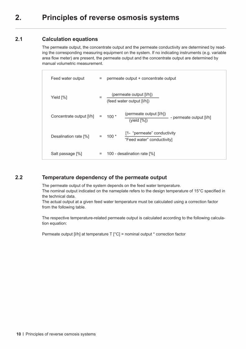
Feed water output = permeate output + concentrate output
Yield [%] = (permeate output [l/h]) (feed water output [l/h])
Concentrate output [l/h] = 100 * (permeate output [l/h])
(yield [%]) - permeate output [l/h]
Desalination rate [%] = 100 * [1- “permeate” conductivity
“Feed water” conductivity]
Salt passage [%] = 100 - desalination rate [%]
2. Principles of reverse osmosis systems
2.1 Calculation equations The permeate output, the concentrate output and the permeate conductivity are determined by read-
ing the corresponding measuring equipment on the system. If no indicating instruments (e.g. variable areaflowmeter)arepresent,thepermeateoutputandtheconcentrateoutputaredeterminedbymanual volumetric measurement.
2.2 Temperature dependency of the permeate output The permeate output of the system depends on the feed water temperature. Thenominaloutputindicatedonthenameplatereferstothedesigntemperatureof15°Cspecifiedin
the technical data. The actual output at a given feed water temperature must be calculated using a correction factor
from the following table.
The respective temperature-related permeate output is calculated according to the following calcula-tion equation:
Permeate output [l/h] at temperature T [°C] = nominal output * correction factor
Principles of reverse osmosis systems
11
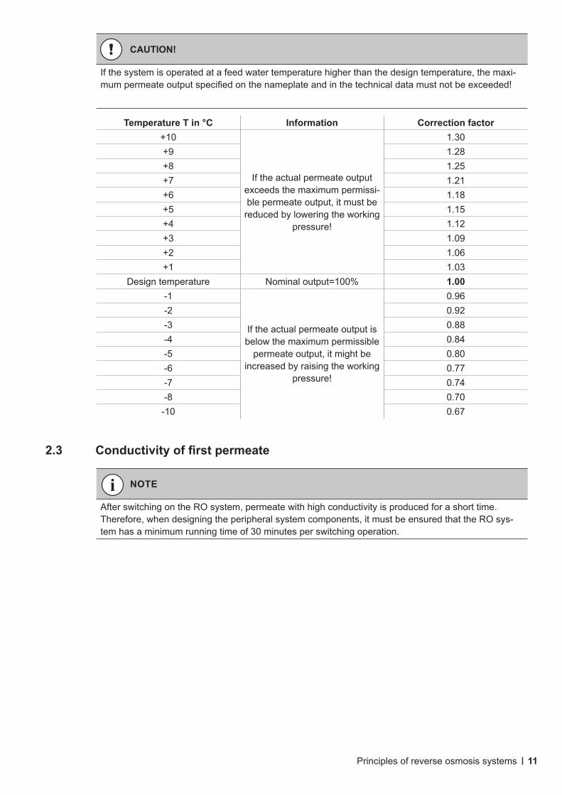
CAUTION!
If the system is operated at a feed water temperature higher than the design temperature, the maxi-mumpermeateoutputspecifiedonthenameplateandinthetechnicaldatamustnotbeexceeded!
Temperature T in °C Information Correction factor +10
If the actual permeate output exceeds the maximum permissi-ble permeate output, it must be reduced by lowering the working
pressure!
1.30+9 1.28+8 1.25+7 1.21+6 1.18+5 1.15+4 1.12+3 1.09+2 1.06+1 1.03
Design temperature Nominal output=100% 1.00-1
If the actual permeate output is below the maximum permissible
permeate output, it might be increased by raising the working
pressure!
0.96-2 0.92-3 0.88-4 0.84-5 0.80-6 0.77-7 0.74-8 0.70
-10 0.67
2.3 Conductivityoffirstpermeate
NOTE
After switching on the RO system, permeate with high conductivity is produced for a short time. Therefore, when designing the peripheral system components, it must be ensured that the RO sys-tem has a minimum running time of 30 minutes per switching operation.
Principles of reverse osmosis systems
12
3. Transport and storage
3.1 Transport to the customer
The transport weight corresponds to the tare weight and can be found in the technical data. However,thesystemmaybedamagedbyextremefrost.Theunitsarefilledwithapreservative/
antifreeze mixture prior to delivery. Thefrostprotectioniseffectivedownto-10°C.
3.2 Storage at the customer’s premises
The maximum storage period of the system in its original packaging is 3 months at 20°C. After that,thepreservativemustbeflushedoutand,iflongerstorageisdesired,replaced.
Thesystemmaybedamagedbyextremefrost.Theunitsarefilledwithapreservative/antifreezemixture prior to delivery.
Thefrostprotectioniseffectivedownto-10°C.
3.1 Transport to the installation site
Use a suitable lifting vehicle to carefully transport the unit to its intended location. Take note of any centre of gravity information on the packages.
CAUTION!
Duringtransport,allunitsmustbesecuredagainstslippingandfallingover!Tippingfromafixedposition is not permitted! If parts of the equipment protrude from the base area of the pallet, then such protruding parts must not be damaged when further parts/equipment are loaded.
Transport and storage
13
4. Technical data / Product description
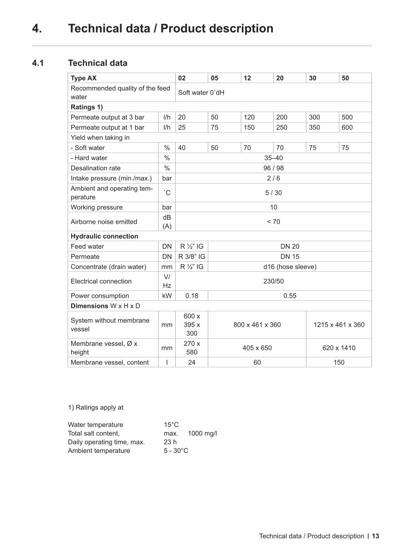
4.1 Technical dataType AX 02 05 12 20 30 50Recommended quality of the feed water Softwater0˚dH
Ratings 1) Permeate output at 3 bar l/h 20 50 120 200 300 500Permeate output at 1 bar l/h 25 75 150 250 350 600Yield when taking in- Soft water % 40 50 70 70 75 75- Hard water % 35–40Desalination rate % 96 / 98Intake pressure (min./max.) bar 2 / 6Ambient and operating tem-perature ˚C 5 / 30
Working pressure bar 10
Airborne noise emitted dB (A) < 70
Hydraulic connectionFeed water DN R ½” IG DN 20Permeate DN R 3/8” IG DN 15Concentrate (drain water) mm R ½” IG d16 (hose sleeve)
Electrical connection V/Hz 230/50
Power consumption kW 0.18 0.55Dimensions W x H x D
System without membrane vessel mm
600 x 395 x 300
800 x 461 x 360 1215 x 461 x 360
Membrane vessel, Ø x height mm 270 x
580 405 x 650 620 x 1410
Membrane vessel, content l 24 60 150
1) Ratings apply at
Water temperature 15°CTotal salt content, max. 1000 mg/lDaily operating time, max. 23 hAmbient temperature 5 - 30°C
Technical data / Product description
14
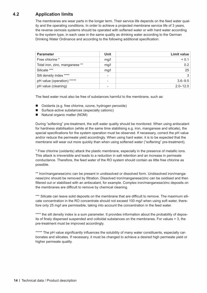
Parameter Unit Limit valueFree chlorine * mg/l < 0.1Total iron, zinc, manganese ** mg/l 0.2Silicate *** mg/l 25Silt density index **** - 3pH value (operation) ***** - 3.6–9.5pH value (cleaning) - 2.0–12.0
The feed water must also be free of substances harmful to the membrane, such as:
Oxidants (e.g. free chlorine, ozone, hydrogen peroxide) Surface-active substances (especially cationic) Natural organic matter (NOM)
During “softening” pre-treatment, the soft water quality should be monitored. When using antiscalant for hardness stabilisation (while at the same time stabilising e.g. iron, manganese and silicate), the specialspecificationsforthesystemoperationmustbeobserved.Ifnecessary,correctthepHvalueand/or reduce the permeate yield accordingly. When using hard water, it is to be expected that the membrane will wear out more quickly than when using softened water (“softening” pre-treatment).
* Free chlorine (oxidants) attack the plastic membrane, especially in the presence of metallic ions. This attack is irreversible and leads to a reduction in salt retention and an increase in permeate conductance. Therefore, the feed water of the RO system should contain as little free chlorine as possible.
** Iron/manganese/zinc can be present in undissolved or dissolved form. Undissolved iron/manga-nese/zincshouldberemovedbyfiltration.Dissolvediron/manganese/zinccanbeoxidisedandthenfilteredoutorstabilisedwithanantiscalant,forexample.Complexiron/manganese/zincdepositsonthemembranesaredifficulttoremovebychemicalcleaning.
***Silicatecanleavesoliddepositsonthemembranethataredifficulttoremove.Themaximumsili-cate concentration in the RO concentrate should not exceed 100 mg/l when using soft water, there-fore only 25 mg/l are permissible, taking into account the concentration in the feed water.
**** the silt density index is a sum parameter. It provides information about the probability of depos-itsoffinelydispersedsuspendedandcolloidalsubstancesonthemembranes.Forvalues>3,thepre-treatment must be improved accordingly.
*****ThepHvaluesignificantlyinfluencesthesolubilityofmanywaterconstituents,especiallycar-
bonates and silicates. If necessary, it must be changed to achieve a desired high permeate yield or higher permeate quality.
4.2 Application limits The membranes are wear parts in the longer term. Their service life depends on the feed water qual-
ity and the operating conditions. In order to achieve a projected membrane service life of 3 years, the reverse osmosis systems should be operated with softened water or with hard water according to the system type, in each case in the same quality as drinking water according to the German DrinkingWaterOrdinanceandaccordingtothefollowingadditionalspecification:
Technical data / Product description
15
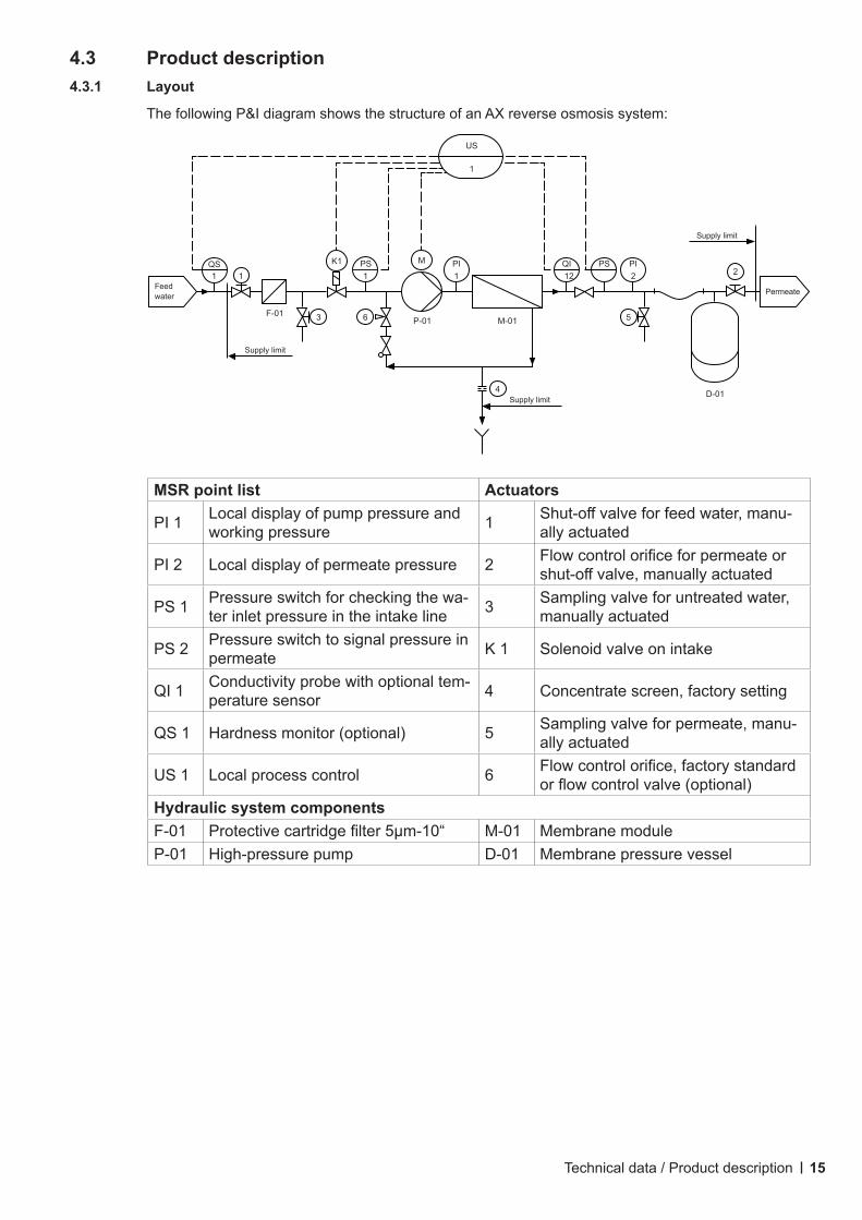
4.3 Product description4.3.1 Layout
The following P&I diagram shows the structure of an AX reverse osmosis system:
MSR point list Actuators
PI 1 Local display of pump pressure and working pressure 1 Shut-offvalveforfeedwater,manu-
ally actuated
PI 2 Local display of permeate pressure 2 Flowcontrolorificeforpermeateorshut-offvalve,manuallyactuated
PS 1 Pressure switch for checking the wa-ter inlet pressure in the intake line 3 Sampling valve for untreated water,
manually actuated
PS 2 Pressure switch to signal pressure in permeate K 1 Solenoid valve on intake
QI 1 Conductivity probe with optional tem-perature sensor 4 Concentrate screen, factory setting
QS 1 Hardness monitor (optional) 5 Sampling valve for permeate, manu-ally actuated
US 1 Local process control 6 Flowcontrolorifice,factorystandardorflowcontrolvalve(optional)
Hydraulic system componentsF-01 Protectivecartridgefilter5µm-10“ M-01 Membrane moduleP-01 High-pressure pump D-01 Membrane pressure vessel
Technical data / Product description
QI12 2
PS PI
5
QS1 1
F-01
K1 PS1
3 6 P-01 M-01
4
US
1
M PI1 2
D-01
Supply limit
PermeateFeed water
Supply limit
Supply limit
16
4.3.2 Function
The RO feed water reaches the HP pump via a residual hardness monitor (optional accessory, only whenusingsoftenedwater)andaprotectivecartridgefilter(gradeoffiltration5µm).Thispumpcon-veys the water at high pressure (level depends on the size of the system and the desired permeate pressure) through the semi-permeable membranes.
Water largely freed from salts passes through the membranes and forms the permeate (desired product). The retained salts are continuously discharged with the concentrate (drain water to the sewer).
An integrated controller monitors and controls all important functions of the RO system during per-meate production and during downtimes.
It controls the HP pump and records the permeate conductivity, furthermore it monitors the inlet pressure and the residual hardness of the feed water (if an optional residual hardness monitor is present),aswellasthepermeatepressure.Alloperating,shut-down,flushingandfaultstatusesareshown in plain text on the display, and faults are signalled by a red LED. A fault message can be sent to the BMS via the alarm relay.
Technical data / Product description
17
5. Installation and assembly
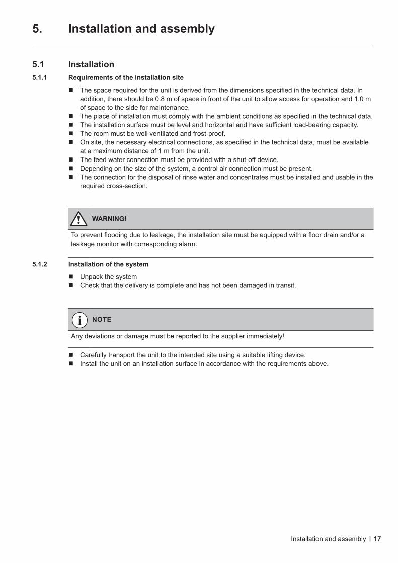
5.1 Installation5.1.1 Requirements of the installation site
Thespacerequiredfortheunitisderivedfromthedimensionsspecifiedinthetechnicaldata.Inaddition, there should be 0.8 m of space in front of the unit to allow access for operation and 1.0 m of space to the side for maintenance.
Theplaceofinstallationmustcomplywiththeambientconditionsasspecifiedinthetechnicaldata. Theinstallationsurfacemustbelevelandhorizontalandhavesufficientload-bearingcapacity. The room must be well ventilated and frost-proof. Onsite,thenecessaryelectricalconnections,asspecifiedinthetechnicaldata,mustbeavailable
at a maximum distance of 1 m from the unit. Thefeedwaterconnectionmustbeprovidedwithashut-offdevice. Depending on the size of the system, a control air connection must be present. The connection for the disposal of rinse water and concentrates must be installed and usable in the
required cross-section.
5.1.2 Installation of the system
Unpack the system Check that the delivery is complete and has not been damaged in transit.
Carefully transport the unit to the intended site using a suitable lifting device. Install the unit on an installation surface in accordance with the requirements above.
WARNING!
Topreventfloodingduetoleakage,theinstallationsitemustbeequippedwithafloordrainand/oraleakage monitor with corresponding alarm.
NOTE
Any deviations or damage must be reported to the supplier immediately!
Installation and assembly
18
5.2 Water connections5.2.1 Requiredqualificationofassemblypersonnel
5.2.2 Establishing the water connections
Feed water
Remove the sealing disk from the screw connector in the feed water inlet and keep it. Connectthefeedwatertothefeedwaterconnectionthroughashut-offvalve.
Permeate
Remove the sealing disks from the screw connector in the permeate outlet and keep them. Connectthepermeateoutletlinetothepermeateinletoftheconsumer(e.g.thehumidifier).
Concentrate
Remove the sealing disk from the screw connector in the concentrate outlet and keep it. Routetheconcentrateoutletlineinafree-flowingdroptothefreewaterdrainalongtheshortest
possiblepath.Drainwatermustbeabletoflowoutwithoutanybackwaterforming.
The following applies only to systems without a membrane pressure vessel:
WARNING!
When the system is not in operation, the back pressure must not exceed 0.3 bar. The cross-sec-tion of the on-site permeate line to the consumer must not be larger by more than one rated width than the permeate outlet.
Ifthebackpressureis>0.3barandthereisariskofpermeateflowingback,anon-returnvalvemust be installed in the permeate line.
Noshut-offdevicewithoutapressurereliefdevicemaybeinstalledinthepermeateline.
NOTE
The water connection must only be carried out by trained specialist personnel. General directives (DIN, DVGW, SVGW, ÖKGW) and local installation regulations must be observed when installing the system.
NOTE
All plumbing connections must be connected while not under pressure. Do not crush or kink hoses; connect hose connections securely. Concentrate and drain lines must be routed to the free waterdrainwithadrop.Sealingdiscsarenotpresentinsystemswithflangeconnections.
Installation and assembly
19
DANGER!
The electrical installation must be carried out by an electrician in compliance with the installation guidelinesoftheVDE,utilitysuppliers,factorystandards,etc.accordingtothevalidcountry-specificregulations.
DANGER!
Before connecting the system to the power supply, make sure that the corresponding on-site main switchisswitchedoff.
NOTE
When using a 3-phase AC supply, check the direction of rotation of the HP pump for clockwise rota-tion.
5.3 Electrical connection5.2.1 Requiredqualificationofassemblypersonnel
5.3.2 Establishing the electrical connections
The internal system components are already pre-wired with the controller on delivery. Thepowersupplytothesystemmustbeestablished,checkedandfusedaccordingtothespecifi-
cations in the electrical wiring diagram. For systems supplied with a mains cable/plug, a CEE AC power point fused in accordance with the
system power requirements (see “Technical data”) must be installed within reach of the length of the mains cable.
For systems that require a 3-phase AC supply, the power supply to the system must be provided by the customer.
5.3.3 Connection of external signals from and messages to BMS
Connect the permeate container level or the permeate outlet pressure switch the forced stop of the residual hardness monitor the centralised alarm according to the electrical wiring diagram.
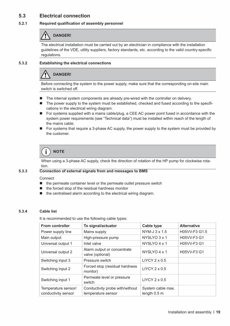
From controller To signal/actuator Cable type AlternativePower supply line Mains supply NYM-J 3 x 1.5 H05VV-F3 G1.5Main output High-pressure pump NYSLYO 3 x 1 H05VV-F3 G1Universal output 1 Inlet valve NYSLYO 4 x 1 H05VV-F3 G1
Universal output 2 Alarm output or concentrate valve (optional) NYSLYO 4 x 1 H05VV-F3 G1
Switching input 3 Pressure switch LIYCY 2 x 0.5
Switching input 2 Forced stop (residual hardness monitor) LIYCY 2 x 0.5
Switching input 1 Permeate level or pressure switch LIYCY 2 x 0.5
Temperature sensor/conductivity sensor
Conductivity probe with/without temperature sensor
System cable max. length 0.5 m
5.3.4 Cable list
It is recommended to use the following cable types:
Installation and assembly

20
5.3.5 Terminal connection table
No. Name Use Allocation SpecificationTerminalsinfrontoftherelays,loweredgeofthecircuitboard:5mmgrid,forsolid/finelystranded conductors up to 1.5 mm²T1
Supply, feed (Power IN) Supply
N230V, 50...60Hz, 6,3 ATT2 L
T3 PET4
Main output(Main Out1) High-pressure pump
PE Normally open relay output, wet, via 6.3 AT fuse
T5 NT6 L (NO contact)T7
Universal output 2(Uni Out 2) Inlet valve
PE Normally open relay output, wet, via 6.3 AT fuse
T8 NT9 L (NO contact)
T10Universal output 2(Uni Out 2)
Alarm output (stand-ard) or concentrate flushvalve
NC (normally closed contact)
Relay changeover con-tact, dry (not fused!)T11 R (Root)
T12 NO (normally open)
Terminalsonthesideedgeofthecircuitboard:2.5mmgrid,forsolid/finelystrandedcon-ductors up to 0.5 mm²T16
No functionAll board spaces are not allocated with terminals!
T17T18T19T20T21T22 Auxiliary supply Not required! Uv (+5V DC) At 100 OhmT23
Switching input 3 Pressure switch of the RO feed
IN For external dry nor-mally open / normally closed contactT24 GND
T25Switching input 2 Forced stop
IN For external dry nor-mally open / normally closed contactT26 GND
T27Switching input 1 Tank level
IN For external dry nor-mally open / normally closed contactT28 GND
T29 Temperature sensor (Temp)
Temperature sensor (if present)
IN (wire Ws)KTY81-210 required
T30 GND (wire Br)T31
Conductivity sensor (LF)
Conductivity sensor(screen, if present — do not use)
INConductivity sensor K=0.2T32 GND
T33
Installation and assembly
21
6. Commissioning and decommissioning
6.1 Commissioning6.1.1 Qualificationofcommissioningpersonnel
6.1.2 Flushing out the preservative
The unit is supplied with the controller set to OFF mode. After switching on the mains power, the actua-tors connected to the controller (pump, input valve) do not switch on independently.
Make a temporary hose connection between the sampling valve (5 — if present) or (if necessary) between the permeate outlet and the sewage duct.
Fully open the pump control valve (if present), pressure control valve (6 — if present), concentrate control valve (4 — if present) and permeate outlet valve (2)
Open feed water inlet Switch on the main switch (if present) or switch on the power supply to the controller on site. Opentheinletvalveviathecontrolpanel(sub-menu“Diagnostics”—Inletvalve)andflushthe
system for at least 30 minutes without switching on the HP pump, using only feed water pressure. Exit the “Diagnostics” sub-menu — the inlet valve closes again Remove the temporary hose connection between the sampling valve (5 — if present) or (if nec-
essary) between the permeate outlet and the sewage duct and reconnect the connection line for permeate to the consumer.
6.1.3 Setting up automatic mode
Afterflushingoutthepreservative,setautomaticmodeviatheoperatingmodesub-menuonthecon-troller by selecting “Operating mode ON”.
6.1.4 Configuringpermeateoutputandyield
WithtypeCaROandCaROEDsystems,itisnotnecessarytoconfigurethepermeateoutputandyield,astheflowratesareputintothecorrectproportionsbyself-regulatingorifices.
6.1.5 Configuringpermeateoutletpressure
The permeate outlet pressure can be selected in the range between 1 and 3 bar on pressure switch
WARNING!
Thepreservativesolutioncontains1.5%sodiumbisulphiteand20%glycerine.Theflushed-outpre-servative solution must be discharged into the sewage system in accordance with the locally applica-ble discharge regulations.
CAUTION!
Thesystemmustbecommissionedbyqualifiedspecialistpersonnel.
NOTE
Before commissioning the system, all screw connections must be tightened.
Commissioning and decommissioning
22
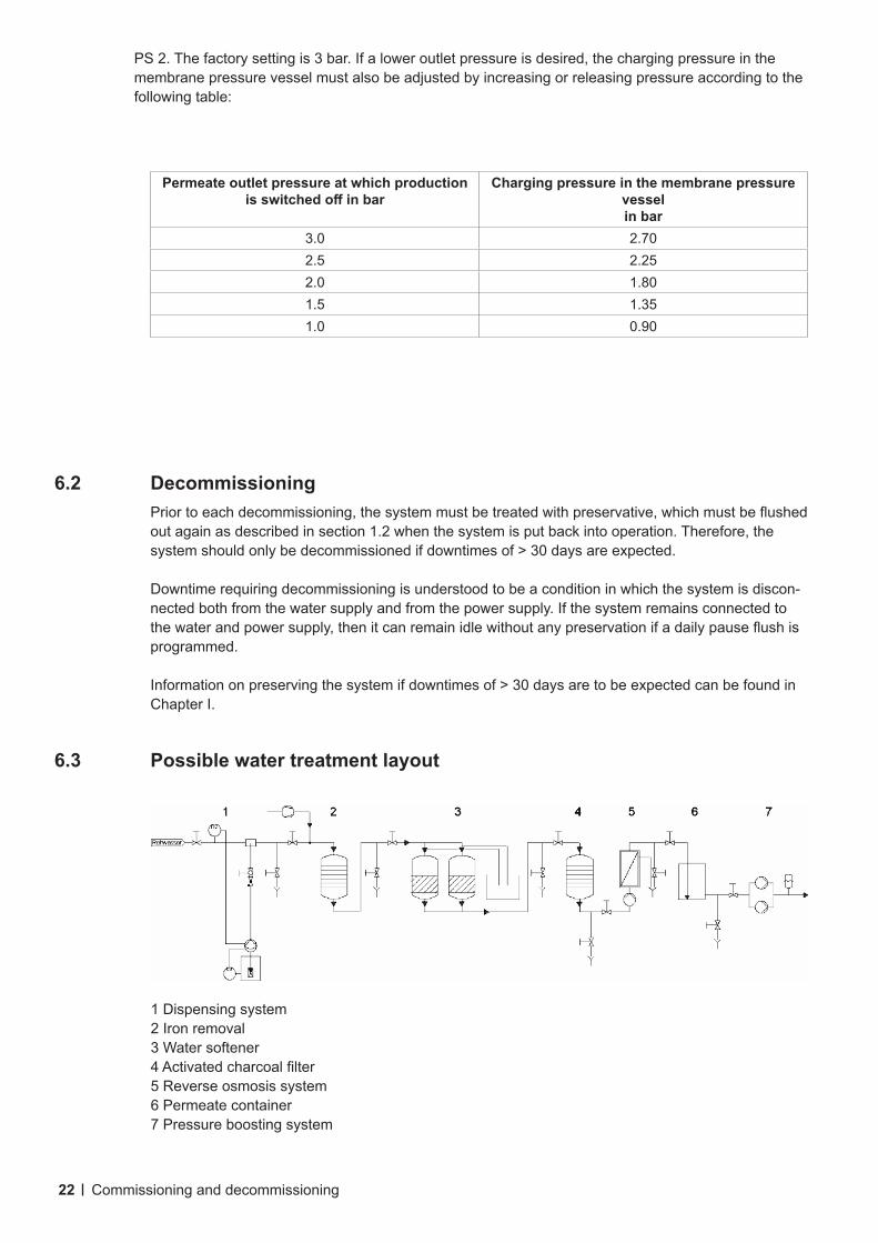
Permeate outlet pressure at which production isswitchedoffinbar
Charging pressure in the membrane pressure vesselin bar
3.0 2.702.5 2.252.0 1.801.5 1.351.0 0.90
6.2 Decommissioning Priortoeachdecommissioning,thesystemmustbetreatedwithpreservative,whichmustbeflushed
out again as described in section 1.2 when the system is put back into operation. Therefore, the systemshouldonlybedecommissionedifdowntimesof>30daysareexpected.
Downtime requiring decommissioning is understood to be a condition in which the system is discon-nected both from the water supply and from the power supply. If the system remains connected to thewaterandpowersupply,thenitcanremainidlewithoutanypreservationifadailypauseflushisprogrammed.
Informationonpreservingthesystemifdowntimesof>30daysaretobeexpectedcanbefoundinChapter I.
6.3 Possible water treatment layout
PS 2. The factory setting is 3 bar. If a lower outlet pressure is desired, the charging pressure in the membrane pressure vessel must also be adjusted by increasing or releasing pressure according to the following table:
Commissioning and decommissioning
1 Dispensing system2 Iron removal3 Water softener4Activatedcharcoalfilter5 Reverse osmosis system6 Permeate container7 Pressure boosting system
23
7. Control panel
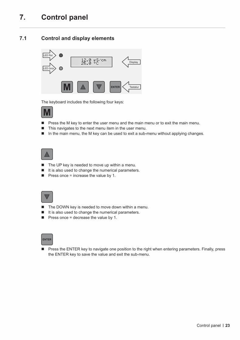
7.1 Control and display elements
The keyboard includes the following four keys:
Press the M key to enter the user menu and the main menu or to exit the main menu. This navigates to the next menu item in the user menu. In the main menu, the M key can be used to exit a sub-menu without applying changes.
The UP key is needed to move up within a menu. It is also used to change the numerical parameters. Press once = increase the value by 1.
The DOWN key is needed to move down within a menu. It is also used to change the numerical parameters. Press once = decrease the value by 1.
Press the ENTER key to navigate one position to the right when entering parameters. Finally, press the ENTER key to save the value and exit the sub-menu.
Control panel
LED Rot
LED Grün
M ENTER Tastatur
Display
M
ENTER
24
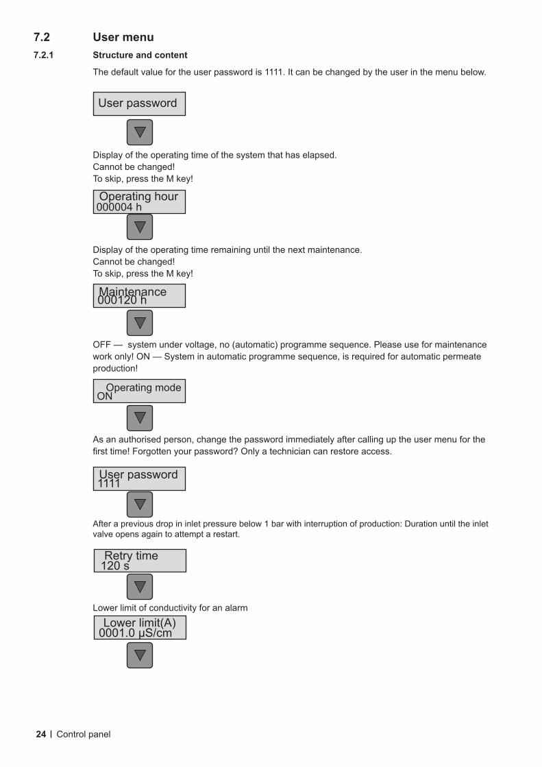
7.2 User menu7.2.1 Structure and content
The default value for the user password is 1111. It can be changed by the user in the menu below.
Display of the operating time of the system that has elapsed. Cannot be changed! To skip, press the M key!
Display of the operating time remaining until the next maintenance. Cannot be changed! To skip, press the M key!
OFF — system under voltage, no (automatic) programme sequence. Please use for maintenance work only! ON — System in automatic programme sequence, is required for automatic permeate production!
As an authorised person, change the password immediately after calling up the user menu for the firsttime!Forgottenyourpassword?Onlyatechniciancanrestoreaccess.
After a previous drop in inlet pressure below 1 bar with interruption of production: Duration until the inlet valve opens again to attempt a restart.
Lower limit of conductivity for an alarm
Control panel
User password
Operating modeON
User password1111
Retry time120 s
Lower limit(A)0001.0 μS/cm
Operating hour000004 h
Maintenance000120 h

25
Lower limit of conductivity for a warning
Upper limit of conductivity for a warning
Upper limit of conductivity for an alarm
Systemresponsetoaconductivityalarm.Youcanselect“Switchoff”and“Donotswitchoff”.Select“Switchoff”onlyifenoughpermeateispre-producedthatwillsufficeuntilatechnicianarrives.
Lower limit of temperature for an alarm
Lower limit of temperature for a warning
Upper limit of temperature for a warning
Upper limit of temperature for an alarm
Systemresponsetoatemperaturealarm.Youcanselect“Switchoff”and“Donotswitchoff”.Select“Switchoff”onlyifenoughpermeateispre-producedthatwillsufficeuntilatechnicianarrives.
Control panel
Response Syst Tdonotswitchoff
Upper limit(A)40.0 oC
Upper limit(W)90.0 oC
Lower limit(W)05.0 oC
Lower limit(A)02.0 oC
Response Syst. conductivitydonotswitchoff
Upper limit(A)00250 μS/cm
Upper limit(W)0023.0 μS/cm
Lower limit(W)9002.0 μS/cm
26
M ENTER
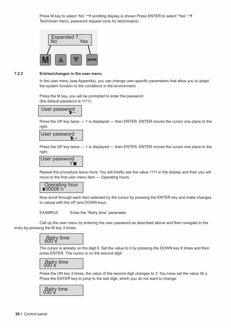
7.2.2 Entries/changes in the user menu
Intheusermenu(seeAppendix),youcanchangeuser-specificparametersthatallowyoutoadaptthe system function to the conditions in the environment.
Press the M key, you will be prompted to enter the password (the default password is 1111):
Press the UP key twice — 1 is displayed — then ENTER. ENTER moves the cursor one place to the right.
Press the UP key twice — 1 is displayed — then ENTER. ENTER moves the cursor one place to the right.
Repeatthisproceduretwicemore.Youwillbrieflyseethevalue1111inthedisplayandthenyouwillmovetothefirstusermenuitem—Operatinghours.
Now scroll through each item selected by the cursor by pressing the ENTER key and make changes to values with the UP and DOWN keys.
EXAMPLE: Enter the “Retry time” parameter
Call up the user menu by entering the user password as described above and then navigate to the entry by pressing the M key 3 times:
The cursor is already on the digit 6. Set the value to 0 by pressing the DOWN key 6 times and then press ENTER. The cursor is on the second digit:
Press the ON key 3 times, the value of the second digit changes to 3. You have set the value 30 s. Press the ENTER key to jump to the last digit, which you do not want to change.
Control panel
Operating hour00006 h
Retry time000 s
Retry time600 s
Retry time030 s
User password----
User password1111
User password1---
Expanded?No Yes
ENTER
Press M key to select “No” scrolling display is shown Press ENTER to select “Yes” Technician menu, password request (only for technicians)
27
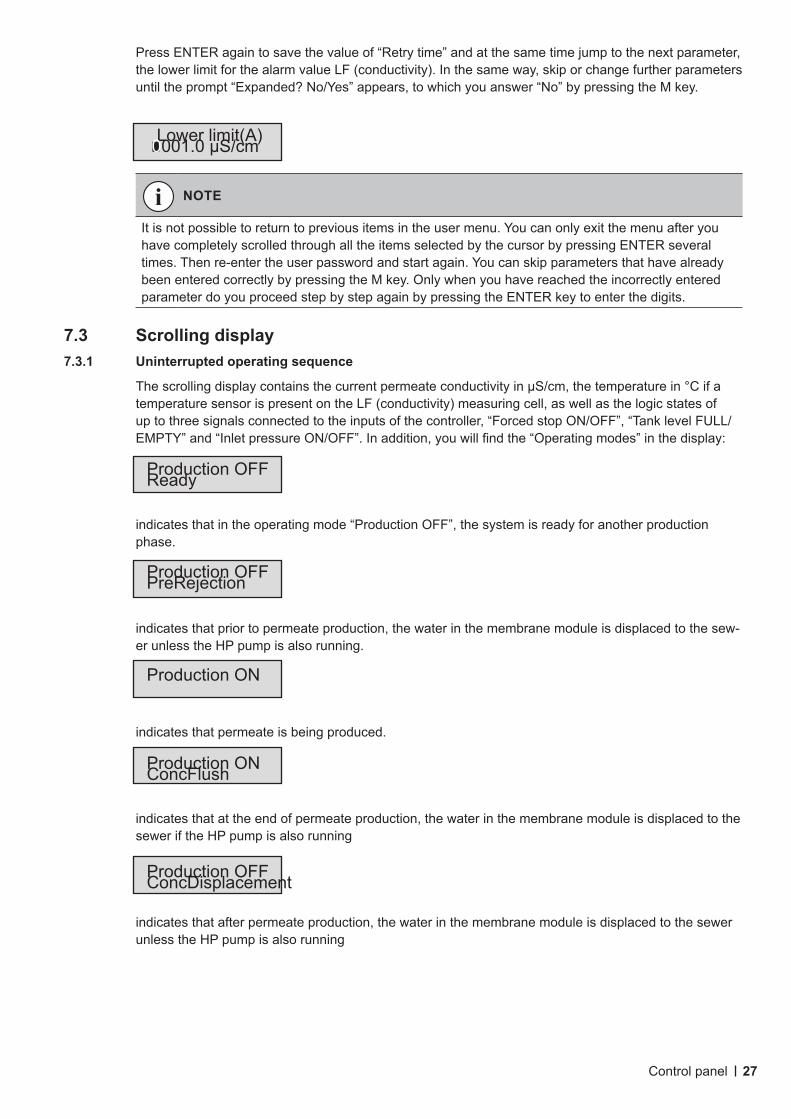
Press ENTER again to save the value of “Retry time” and at the same time jump to the next parameter, the lower limit for the alarm value LF (conductivity). In the same way, skip or change further parameters untiltheprompt“Expanded?No/Yes”appears,towhichyouanswer“No”bypressingtheMkey.
7.3 Scrolling display7.3.1 Uninterrupted operating sequence
ThescrollingdisplaycontainsthecurrentpermeateconductivityinµS/cm,thetemperaturein°Cifatemperature sensor is present on the LF (conductivity) measuring cell, as well as the logic states of up to three signals connected to the inputs of the controller, “Forced stop ON/OFF”, “Tank level FULL/ EMPTY”and“InletpressureON/OFF”.Inaddition,youwillfindthe“Operatingmodes”inthedisplay:
indicates that in the operating mode “Production OFF”, the system is ready for another production phase.
indicates that prior to permeate production, the water in the membrane module is displaced to the sew-er unless the HP pump is also running.
indicates that permeate is being produced.
indicates that at the end of permeate production, the water in the membrane module is displaced to the sewer if the HP pump is also running
indicates that after permeate production, the water in the membrane module is displaced to the sewer unless the HP pump is also running
NOTE
It is not possible to return to previous items in the user menu. You can only exit the menu after you have completely scrolled through all the items selected by the cursor by pressing ENTER several times. Then re-enter the user password and start again. You can skip parameters that have already been entered correctly by pressing the M key. Only when you have reached the incorrectly entered parameter do you proceed step by step again by pressing the ENTER key to enter the digits.
Control panel
Lower limit(A)0001.0 μS/cm
Production OFFReady
Production ON
Production OFFPreRejection
Production OFFConcDisplacement
Production ONConcFlush
28
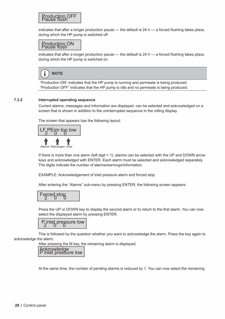
indicatesthatafteralongerproductionpause—thedefaultis24h—aforcedflushingtakesplace,duringwhichtheHPpumpisswitchedoff
indicatesthatafteralongerproductionpause—thedefaultis24h—aforcedflushingtakesplace,during which the HP pump is switched on
7.3.2 Interrupted operating sequence Current alarms, messages and information are displayed, can be selected and acknowledged on a
screen that is shown in addition to the uninterrupted sequence in the rolling display.
The screen that appears has the following layout:
Ifthereismorethanonealarm(leftdigit>1),alarmscanbeselectedwiththeUPandDOWNarrowkeys and acknowledged with ENTER. Each alarm must be selected and acknowledged separately. The digits indicate the number of alarms/warnings/information.
EXAMPLE: Acknowledgement of inlet pressure alarm and forced stop
After entering the “Alarms” sub-menu by pressing ENTER, the following screen appears:
PresstheUPorDOWNkeytodisplaythesecondalarmortoreturntothefirstalarm.You can now select the displayed alarm by pressing ENTER.
This is followed by the question whether you want to acknowledge the alarm. Press the key again to acknowledge the alarm. After pressing the M key, the remaining alarm is displayed.
At the same time, the number of pending alarms is reduced by 1. You can now select the remaining
NOTE
“Production ON” indicates that the HP pump is running and permeate is being produced.“Production OFF” indicates that the HP pump is idle and no permeate is being produced.
Control panel
Alarme Warnungen Infos
Production ONPauseflush
Production OFFPauseflush
LF PErm too low3 0 0
AcknowledgeP inlet pressure low
Forced stop2 0 0
P inlet pressure low2 0 0
29
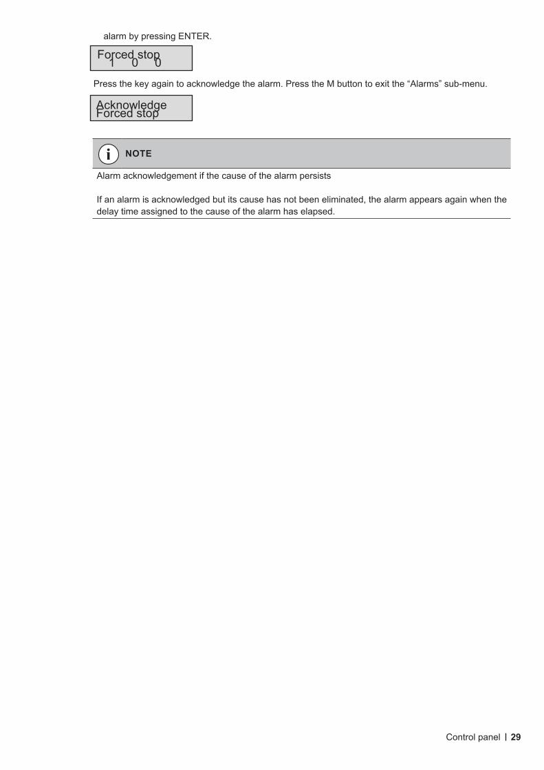
alarm by pressing ENTER.
Press the key again to acknowledge the alarm. Press the M button to exit the “Alarms” sub-menu.
NOTE
Alarm acknowledgement if the cause of the alarm persists
If an alarm is acknowledged but its cause has not been eliminated, the alarm appears again when the delay time assigned to the cause of the alarm has elapsed.
Control panel
AcknowledgeForced stop
Forced stop1 0 0
30
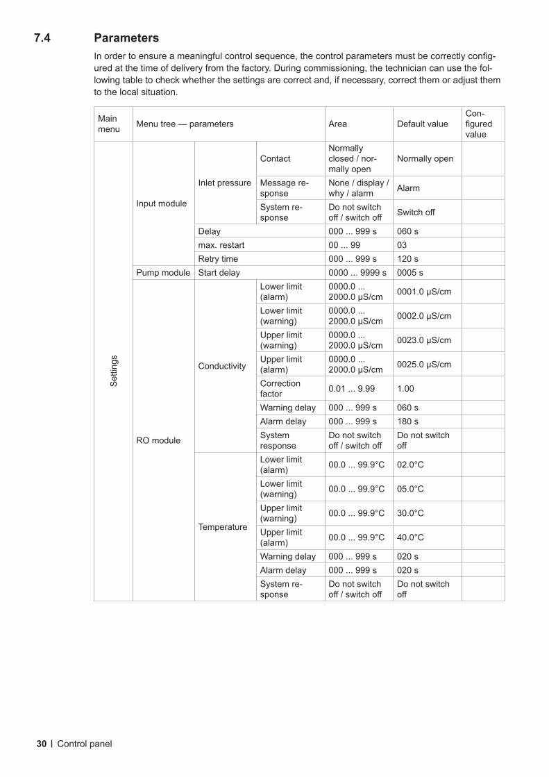
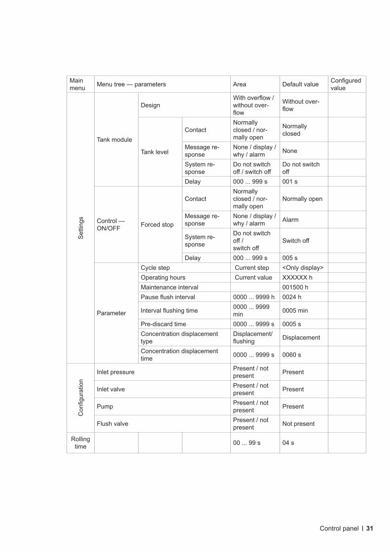
7.4 Parameters Inordertoensureameaningfulcontrolsequence,thecontrolparametersmustbecorrectlyconfig-
ured at the time of delivery from the factory. During commissioning, the technician can use the fol-lowing table to check whether the settings are correct and, if necessary, correct them or adjust them to the local situation.
Main menu Menu tree — parameters Area Default value
Con-figuredvalue
Setti
ngs
Input module
Inlet pressure
ContactNormally closed / nor-mally open
Normally open
Message re-sponse
None / display / why / alarm Alarm
System re-sponse
Do not switch off/switchoff Switchoff
Delay 000 ... 999 s 060 smax. restart 00 ... 99 03Retry time 000 ... 999 s 120 s
Pump module Start delay 0000 ... 9999 s 0005 s
RO module
Conductivity
Lower limit (alarm)
0000.0 ... 2000.0µS/cm 0001.0µS/cm
Lower limit (warning)
0000.0 ... 2000.0µS/cm 0002.0µS/cm
Upper limit (warning)
0000.0 ... 2000.0µS/cm 0023.0µS/cm
Upper limit (alarm)
0000.0 ... 2000.0µS/cm 0025.0µS/cm
Correction factor 0.01 ... 9.99 1.00
Warning delay 000 ... 999 s 060 sAlarm delay 000 ... 999 s 180 sSystem response
Do not switch off/switchoff
Do not switch off
Temperature
Lower limit (alarm) 00.0 ... 99.9°C 02.0°C
Lower limit (warning) 00.0 ... 99.9°C 05.0°C
Upper limit (warning) 00.0 ... 99.9°C 30.0°C
Upper limit (alarm) 00.0 ... 99.9°C 40.0°C
Warning delay 000 ... 999 s 020 sAlarm delay 000 ... 999 s 020 sSystem re-sponse
Do not switch off/switchoff
Do not switch off
Control panel
31
Main menu Menu tree — parameters Area Default value Configured
valueSe
tting
s
Tank module
DesignWithoverflow/without over-flow
Without over-flow
Tank level
ContactNormally closed / nor-mally open
Normally closed
Message re-sponse
None / display / why / alarm None
System re-sponse
Do not switch off/switchoff
Do not switch off
Delay 000 ... 999 s 001 s
Control — ON/OFF Forced stop
ContactNormally closed / nor-mally open
Normally open
Message re-sponse
None / display / why / alarm Alarm
System re-sponse
Do not switch off/switchoff
Switchoff
Delay 000 ... 999 s 005 s
Parameter
Cycle step Current step <Onlydisplay>Operating hours Current value XXXXXX hMaintenance interval 001500 hPauseflushinterval 0000 ... 9999 h 0024 h
Intervalflushingtime 0000 ... 9999 min 0005 min
Pre-discard time 0000 ... 9999 s 0005 sConcentration displacement type
Displacement/flushing Displacement
Concentration displacement time 0000 ... 9999 s 0060 s
Configuration
Inlet pressure Present / not present Present
Inlet valve Present / not present Present
Pump Present / not present Present
Flush valve Present / not present Not present
Rolling time 00 ... 99 s 04 s
Control panel
32
8. Fault elimination
8.1 General information By using high-quality individual components and due to the built-in safety and monitoring devices, a
very high degree of operational reliability is achieved.
Shouldamalfunctionneverthelessoccur,thefaultcanbeeasilyidentifiedandthecauseeliminatedusing the fault table set out below.
If serious malfunctions occur, please contact the manufacturer (see nameplate).
8.1.1 Fault reporting to the manufacturer
Toensureeffectivetroubleshooting,pleasehavethefollowinginformationready:
Order number (if available) Item number (if available) System type Operations logs and maintenance logs (if available) from the last year
8.1.2 Fault indication and reset
Red alarm LED lights up Fault message as indication in the display For resetting alarm messages on the control panel, please refer to the corresponding section in
chapter 7 - Control panel!
8.2 Fault analysis and elimination8.3 Flushing the concentrate
WARNING!
Faulteliminationmayonlybecarriedoutbyqualifiedandinstructedpersonnelincompliancewiththe safety regulations in chapter A of this operating manual!
Before starting work, the system must be disconnected from the power supply and secured against being switched on again unintentionally!
All lines must be de-pressurised.
NOTE
Please read the following table containing possible malfunctions before contacting the manufactur-er’s service department!
Fault elimination
33
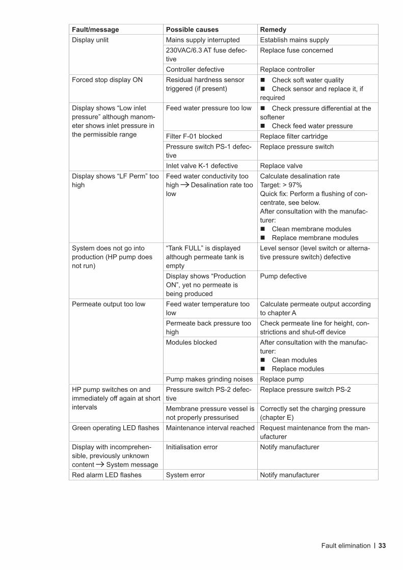
Fault/message Possible causes RemedyDisplay unlit Mains supply interrupted Establish mains supply
230VAC/6.3 AT fuse defec-tive
Replace fuse concerned
Controller defective Replace controllerForced stop display ON Residual hardness sensor
triggered (if present)Check soft water qualityCheck sensor and replace it, if required
Display shows “Low inlet pressure” although manom-eter shows inlet pressure in the permissible range
Feed water pressure too low CheckpressuredifferentialatthesoftenerCheck feed water pressure
Filter F-01 blocked ReplacefiltercartridgePressure switch PS-1 defec-tive
Replace pressure switch
Inlet valve K-1 defective Replace valveDisplay shows “LF Perm” too high
Feed water conductivity too high Desalination rate too low
Calculate desalination rateTarget:>97%Quickfix:Performaflushingofcon-centrate, see below.After consultation with the manufac-turer:Clean membrane modulesReplace membrane modules
System does not go into production (HP pump does not run)
“Tank FULL” is displayed although permeate tank is empty
Level sensor (level switch or alterna-tive pressure switch) defective
Display shows “Production ON”, yet no permeate is being produced
Pump defective
Permeate output too low Feed water temperature too low
Calculate permeate output according to chapter A
Permeate back pressure too high
Check permeate line for height, con-strictionsandshut-offdevice
Modules blocked After consultation with the manufac-turer:Clean modulesReplace modules
Pump makes grinding noises Replace pumpHP pump switches on and immediatelyoffagainatshortintervals
Pressure switch PS-2 defec-tive
Replace pressure switch PS-2
Membrane pressure vessel is not properly pressurised
Correctly set the charging pressure (chapter E)
GreenoperatingLEDflashes Maintenance interval reached Request maintenance from the man-ufacturer
Display with incomprehen-sible, previously unknown content System message
Initialisation error Notify manufacturer
RedalarmLEDflashes System error Notify manufacturer
Fault elimination
34
Whenflushingtheconcentrate,theconcentratesideofthemembrane(s)isflushedatahigherspeedduetotheincreaseintheconcentratevolumeflowand,duetotheassociatedincreaseinshearforces,easilydetachabledepositsareremovedandflushedout.
Flushing the concentrate should last at least 60 minutes and should be carried out as follows: Log the actual values (enter in operations log according to chapter H) Open the concentrate control valve completely or remove the concentrate screen (depending on the type of system). Fully open the pressure control valve (if present) Flush for a min. of 60 minutes Readjust the operating parameters to the set points Wait 10 minutes Log the actual values again (enter in operations log according to chapter H)
NOTE
Ifthepermeateconductivitydoesnotimprovepermanentlyafterconcentrateflushing,themem-branes should be replaced.
Fault elimination
35
9. Inspection and maintenance
9.1 Inspection and maintenance work9.1.1 Safety instructions
9.1.2 General information
The system operator is responsible for logging the operating parameters. A log sheet must be kept for logging the operating parameters, which allows for continuous documentation of the operating param-eters and provides evidence of correct operation. A drop in performance or malfunctions of the RO system can thus be detected and remedied more quickly.
It is recommended to conclude an inspection and maintenance contract with the supplier, who is qualifiedtocarryouttheregularlyrequiredmaintenanceworkonthesystem.Themaintenanceworkisdocumentedonthedesignatedmaintenancelogbythequalifiedpersoncarryingouttheinspectionormaintenance.
WARNING!
Before starting work on electrical installations and equipment, the installation must be checked to ensure that it is de-energised. In addition, the system must be secured against being switched on unintentionally.
Suitable protective clothing appropriate to the hazard must be worn during the maintenance work.
Immediatelyaftercompletionofthemaintenancework,allsafetyandprotectivedevicesmustberefit-ted or put into operation.
CAUTION!
The operator must ensure that all inspection, maintenance, and assembly work is carried out by authorised,qualifiedtechnicians.
Before carrying out any repair or maintenance work, the system must be shut down and secured against being accidentally put into operation.
NOTE
In order to ensure the proper operation and function of the system in the long term, regular mainte-nance work must be carried out and a log of the operating parameters must be kept!
Inspection and maintenance
36
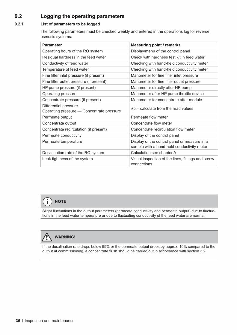
9.2 Logging the operating parameters9.2.1 List of parameters to be logged
The following parameters must be checked weekly and entered in the operations log for reverse osmosis systems:
Parameter Measuring point / remarksOperating hours of the RO system Display/menu of the control panelResidual hardness in the feed water Check with hardness test kit in feed waterConductivity of feed water Checking with hand-held conductivity meterTemperature of feed water Checking with hand-held conductivity meterFinefilterinletpressure(ifpresent) ManometerforfinefilterinletpressureFinefilteroutletpressure(ifpresent) ManometerforfinefilteroutletpressureHP pump pressure (if present) Manometer directly after HP pumpOperating pressure Manometer after HP pump throttle deviceConcentrate pressure (if present) Manometer for concentrate after moduleDifferentialpressureOperating pressure — Concentrate pressure ∆p=calculatefromthereadvalues
Permeate output PermeateflowmeterConcentrate output ConcentrateflowmeterConcentrate recirculation (if present) ConcentraterecirculationflowmeterPermeate conductivity Display of the control panelPermeate temperature Display of the control panel or measure in a
sample with a hand-held conductivity meterDesalination rate of the RO system Calculation see chapter ALeak tightness of the system Visualinspectionofthelines,fittingsandscrew
connections
WARNING!
If the desalination rate drops below 95% or the permeate output drops by approx. 10% compared to the outputatcommissioning,aconcentrateflushshouldbecarriedoutinaccordancewithsection3.2.
NOTE
Slightfluctuationsintheoutputparameters(permeateconductivityandpermeateoutput)duetofluctua-tionsinthefeedwatertemperatureorduetofluctuatingconductivityofthefeedwaterarenormal.
Inspection and maintenance
37
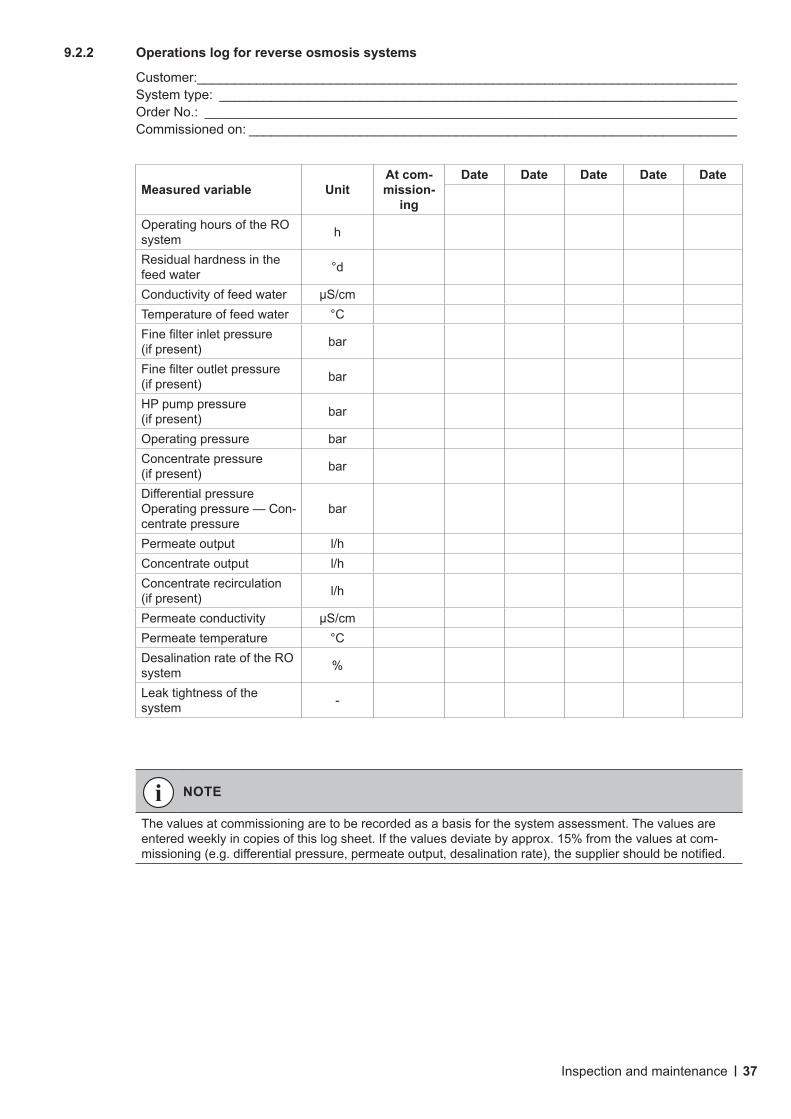
9.2.2 Operations log for reverse osmosis systems
Customer:_________________________________________________________________________ System type: ______________________________________________________________________ Order No.: ________________________________________________________________________ Commissioned on: __________________________________________________________________
Measured variable UnitAt com-mission-
ing
Date Date Date Date Date
Operating hours of the RO system h
Residual hardness in the feed water °d
Conductivity of feed water µS/cmTemperature of feed water °CFinefilterinletpressure(if present) bar
Finefilteroutletpressure(if present) bar
HP pump pressure (if present) bar
Operating pressure barConcentrate pressure (if present) bar
DifferentialpressureOperating pressure — Con-centrate pressure
bar
Permeate output l/hConcentrate output l/hConcentrate recirculation (if present) l/h
Permeate conductivity µS/cmPermeate temperature °CDesalination rate of the RO system %
Leak tightness of the system -
NOTE
The values at commissioning are to be recorded as a basis for the system assessment. The values are entered weekly in copies of this log sheet. If the values deviate by approx. 15% from the values at com-missioning(e.g.differentialpressure,permeateoutput,desalinationrate),thesuppliershouldbenotified.
Inspection and maintenance
38
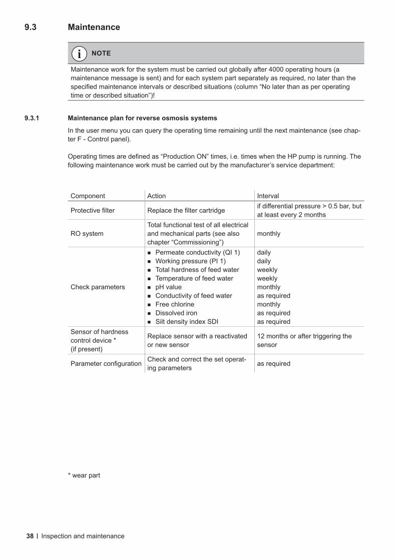
9.3 Maintenance
9.3.1 Maintenance plan for reverse osmosis systems
In the user menu you can query the operating time remaining until the next maintenance (see chap-ter F - Control panel).
Operatingtimesaredefinedas“ProductionON”times,i.e.timeswhentheHPpumpisrunning.Thefollowing maintenance work must be carried out by the manufacturer’s service department:
NOTE
Maintenance work for the system must be carried out globally after 4000 operating hours (a maintenance message is sent) and for each system part separately as required, no later than the specifiedmaintenanceintervalsordescribedsituations(column“Nolaterthanasperoperatingtime or described situation”)!
* wear part
Inspection and maintenance
Component Action Interval
Protectivefilter Replacethefiltercartridge ifdifferentialpressure>0.5bar,butat least every 2 months
RO systemTotal functional test of all electrical and mechanical parts (see also chapter “Commissioning”)
monthly
Check parameters
Permeate conductivity (QI 1)Working pressure (PI 1)Total hardness of feed waterTemperature of feed waterpH valueConductivity of feed waterFree chlorineDissolved ironSilt density index SDI
dailydailyweeklyweeklymonthlyas requiredmonthlyas requiredas required
Sensor of hardness control device *(if present)
Replace sensor with a reactivated or new sensor
12 months or after triggering the sensor
Parameterconfiguration Check and correct the set operat-ing parameters as required
39
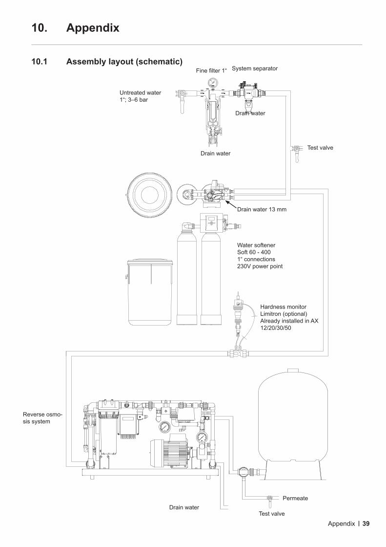
10. Appendix
10.1 Assembly layout (schematic)
Untreated water1“; 3–6 bar
Finefilter1“
Drain waterTest valve
Drain water 13 mm
Drain waterPermeate
Test valve
Water softenerSoft 60 - 4001“ connections230V power point
Hardness monitorLimitron (optional)Already installed in AX 12/20/30/50
Reverse osmo-sis system
Drain water
System separator
Appendix
40
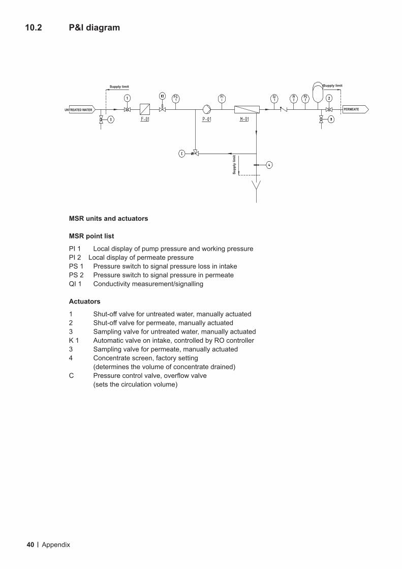
10.2 P&I diagram
MSR units and actuators
MSR point list
PI 1 Local display of pump pressure and working pressurePI 2 Local display of permeate pressurePS 1 Pressure switch to signal pressure loss in intakePS 2 Pressure switch to signal pressure in permeateQI 1 Conductivity measurement/signalling
Actuators
1 Shut-offvalveforuntreatedwater,manuallyactuated2 Shut-offvalveforpermeate,manuallyactuated3 Sampling valve for untreated water, manually actuatedK 1 Automatic valve on intake, controlled by RO controller3 Sampling valve for permeate, manually actuated4 Concentrate screen, factory setting (determines the volume of concentrate drained)C Pressurecontrolvalve,overflowvalve (sets the circulation volume)
Appendix
Supp
ly li
mit
Supply limit
PERMEATEUNTREATED WATER
Supply limit
41
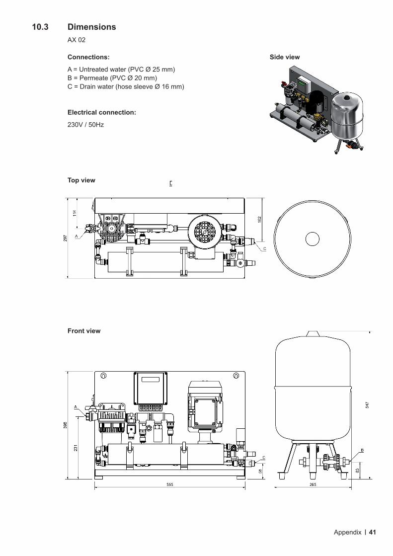
10.3 Dimensions AX 02
Connections: Side view
A = Untreated water (PVC Ø 25 mm) B = Permeate (PVC Ø 20 mm) C = Drain water (hose sleeve Ø 16 mm)
Electrical connection:
230V / 50Hz
Top view
Front view
Appendix
42
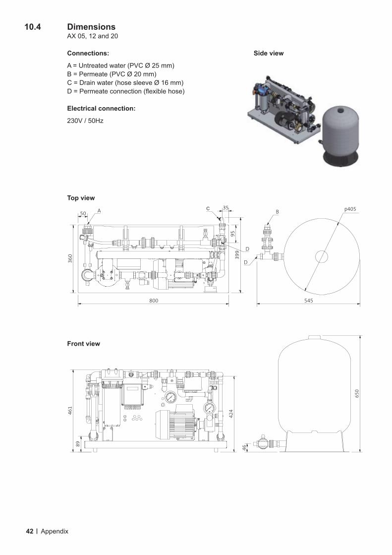
10.4 Dimensions AX 05, 12 and 20
Connections: Side view
A = Untreated water (PVC Ø 25 mm) B = Permeate (PVC Ø 20 mm) C = Drain water (hose sleeve Ø 16 mm) D=Permeateconnection(flexiblehose)
Electrical connection:
230V / 50Hz
Top view
Front view
360 399
95
3550
545
p405A C
D
D
B
800
46
650
89
424461
Appendix
43
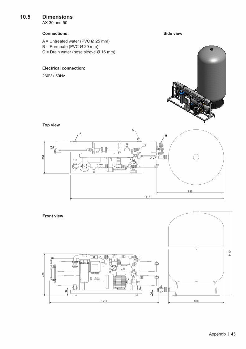
10.5 Dimensions AX 30 and 50
Connections: Side view
A = Untreated water (PVC Ø 25 mm) B = Permeate (PVC Ø 20 mm) C = Drain water (hose sleeve Ø 16 mm)
Electrical connection:
230V / 50Hz
756
64
1410
88
1217 620
466
360
1710
B
D
ACC
D
Top view
Front view
Appendix
©01/2021CondairGmbH.Subjecttoerrorsandtechnicalmodificationswithoutnotice.Thecontentiscorrectatthetimeofgoingtopress.If you have any questions about the documentation, please contact the head office in Germany.
Condair GmbH Parkring 3, 85748 Garching Tel. +49 (0) 89 20 70 08-0, Fax +49 (0) 89 20 70 08-140, www.condair.de
Condair GmbH Regionalcenter SüdParkring 3D-85748 GarchingTel. +49 (0) 89 / 20 70 08-0Fax +49 (0) 89 / 20 70 08-140
Regionalcenter SüdwestZettachring 6D-70567 StuttgartTel. +49 (0) 711 / 25 29 70-0Fax +49 (0) 711 / 25 29 70-40
Regionalcenter MitteNordendstraße 2D-64546 Mörfelden-WalldorfTel. +49 (0) 61 05 / 963 88-0Fax +49 (0) 61 05 / 963 88-40
Regionalcenter WestWerftstraße 25D-40549 DüsseldorfTel. +49 (0) 211 / 54 20 35-0Fax +49 (0) 211 / 54 20 35-60
Regionalcenter NordLüneburger Straße 4D-30880 Laatzen - RethenTel. +49 (0) 511 / 51 54 13 11Fax +49 (0) 511 / 51 54 13 40
Regionalcenter OstChausseestraße 88D-10115 BerlinTel. +49 (0) 30 / 921 03 44 -0Fax +49 (0) 30 / 921 03 44-40
Condair AustriaPerfektastraße 45A-1230 WienTel. +43 (0) 1 / 60 33 111-0Fax +43 (0) 1 / 60 33 111 399