installation and maintenance manual · the installation and maintenance manual is for pentair ......
TRANSCRIPT

Self-Regulating and PoweR lim it ing Heating Cable SyStemS
EN-RaychemSelfRegCable-IM-DOC71 R16Thermal managemenT soluTions
Installation and Maintenance Manual
123456789
1011
General information Pg. 1
Heating cable selection Pg. 3
Heating cable installation Pg. 4
Components installation Pg. 13
Thermostats Pg. 19
Thermal insulation and marking Pg. 19
Power supply and electrical protection Pg. 21
Heating cable testing Pg. 21
Operation, maintenance and pipe repairs Pg. 23
Heating cable damage Pg. 24
Troubleshooting guide Pg. 24
L
N
L
N
1 general informaTion
use of the manual
The Installation and Maintenance manual is for Pentair Thermal Management self-regulating and power limiting heating cable systems on thermally insulated pipes and vessels only. For information regarding other applications contact your Pentair Thermal Management representative.
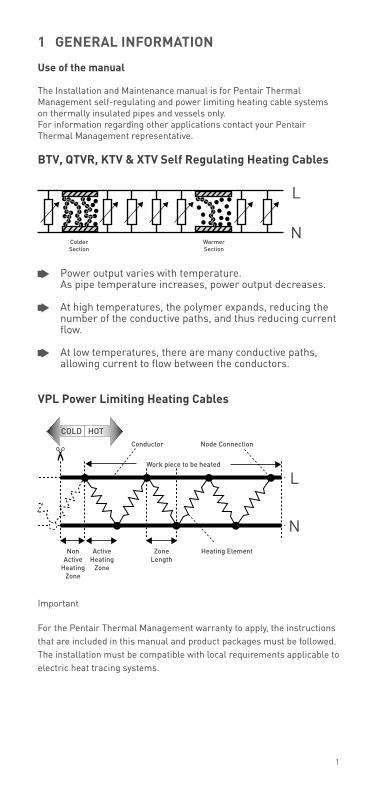
BTV, QTVr, KTV & XTV self regulating heating Cables
Power output varies with temperature. As pipe temperature increases, power output decreases.
At high temperatures, the polymer expands, reducing the number of the conductive paths, and thus reducing current flow.
At low temperatures, there are many conductive paths, allowing current to flow between the conductors.
VPl Power limiting heating Cables
Important
For the Pentair Thermal Management warranty to apply, the instructions that are included in this manual and product packages must be followed. The installation must be compatible with local requirements applicable to electric heat tracing systems.
1
2
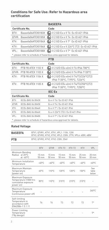
BTV QTVR XTV-T3 XTV-T2 KTV VPL
Minimum Bending Radius at 20°C at -60°C
15 mm50 mm
15 mm50 mm
15 mm50 mm
15 mm50 mm
25 mm50 mm
20 mm20 mm
Minimum Installation Temperature –60°C –60°C –60°C –60°C –60°C –60°C
Maximum Maintain Temperature (power on)
65°C 110°C 120°C 120°C 150°CSee
table below
Maximum Exposure Temperature (1000 hrs cumulative exposure power on)
85°C 110°C 215°C 215°C 215°C –
Maximum Exposure Temperature (continuous power off)
– – – – – 260°C
Self-limiting Temperature in accordance with EN62086-1 5.1.11
T6 T4 T3 T2 T2 T*
Power Limiting Temperature (*By design)
- - - - - T*
Conditions for safe use: refer to hazardous area certification
rated Voltage
Baseefa BTV1, QTVR1, KTV1, XTV1, VPL1: 110V, 120V BTV2, QTVR2, KTV2, XTV2, VPL2: 230V, 277V, VPL4: 400V, 480V
PTB BTV2, QTVR2, KTV2, XTV2: 230V, 254V
BaseefaCertificate no. CodeBTV: Baseefa06ATEX0183X II 2 GD Ex e II T6 Ex tD A21 IP66QTVR: Baseefa06ATEX0185X II 2 GD Ex e II T4 Ex tD A21 IP66XTV: Baseefa06ATEX0184X II 2 GD Ex e II T* Ex tD A21 IP66
KTV: Baseefa06ATEX0186X II 2 GD Ex e II 226°C (T2) Ex tD A21 IP66VPL: Baseefa06ATEX0188X II 2 GD Ex e II T* Ex tD A21 IP66*: please refer to schedule of hazardous area approval for details.
PTBCertificate no. CodeBTV: PTB 98 ATEX 1102 X II 2 G/D EEx e(m) II T6 IP66 T80°CQTVR: PTB 98 ATEX 1103 X II 2 G/D EEx e(m) II T4 IP66 T130°CKTV: PTB 98 ATEX 1104 X II 2 G/D EEx e(m) II T4/T3/226°C(T2)
IP66 T130°C, T195°C, T226°CXTV: PTB 98 ATEX 1105 X II 2 G/D EEx e(m) II T4/T3/250°C(T2)
IP66 T130°C, T195°C, T250°C
ieC exCertificate no. CodeBTV: IECEx BAS 06.0043X Ex e II T6 / Ex tD A21 IP66
QTVR: IECEx BAS 06.0045X Ex e II T4 / Ex tD A21 IP66
XTV: IECEx BAS 06.0044X Ex e II T* / Ex tD A21 IP66
KTV: IECEx BAS 06.0046X Ex e II 226°C (T2) / Ex tD A21 IP66
VPL: IECEx BAS 06.0048X Ex e II T* / Ex tD A21 IP66
*: please refer to schedule of hazardous area approval for details.
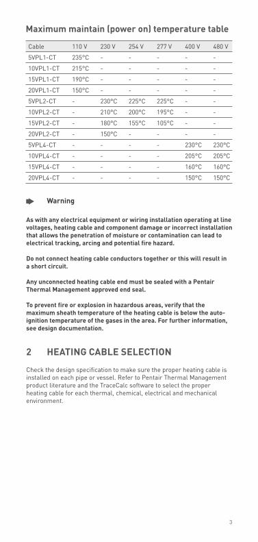
Cable 110 V 230 V 254 V 277 V 400 V 480 V
5VPL1-CT 235°C - - - - -
10VPL1-CT 215°C - - - - -
15VPL1-CT 190°C - - - - -
20VPL1-CT 150°C - - - - -
5VPL2-CT - 230°C 225°C 225°C - -
10VPL2-CT - 210°C 200°C 195°C - -
15VPL2-CT - 180°C 155°C 105°C - -
20VPL2-CT - 150°C - - - -
5VPL4-CT - - - - 230°C 230°C
10VPL4-CT - - - - 205°C 205°C
15VPL4-CT - - - - 160°C 160°C
20VPL4-CT - - - - 150°C 150°C
Warning
as with any electrical equipment or wiring installation operating at line voltages, heating cable and component damage or incorrect installation that allows the penetration of moisture or contamination can lead to electrical tracking, arcing and potential fire hazard.
Do not connect heating cable conductors together or this will result in a short circuit.
any unconnected heating cable end must be sealed with a Pentair Thermal management approved end seal.
To prevent fire or explosion in hazardous areas, verify that the maximum sheath temperature of the heating cable is below the auto-ignition temperature of the gases in the area. for further information, see design documentation.
2 heaTing CaBle seleCTion Check the design specification to make sure the proper heating cable is installed on each pipe or vessel. Refer to Pentair Thermal Management product literature and the TraceCalc software to select the proper heating cable for each thermal, chemical, electrical and mechanical environment.
maximum maintain (power on) temperature table
3
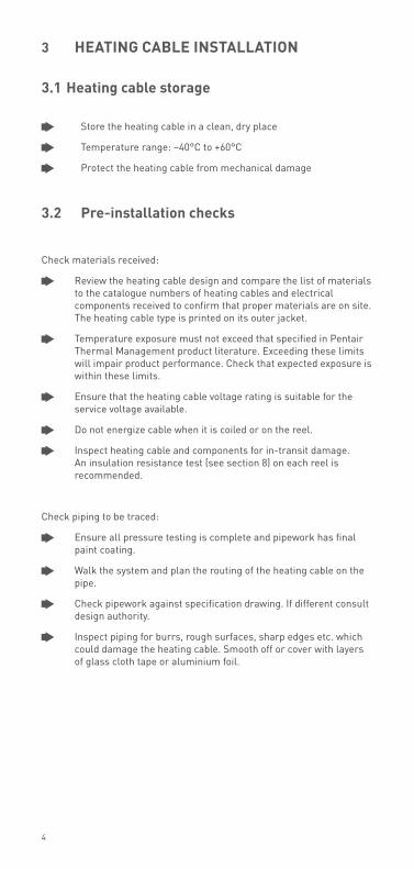
3 heaTing CaBle insTallaTion
3.1 heating cable storage
Store the heating cable in a clean, dry place
Temperature range: –40°C to +60°C
Protect the heating cable from mechanical damage
3.2 Pre-installation checks
Check materials received:
Review the heating cable design and compare the list of materials to the catalogue numbers of heating cables and electrical components received to confirm that proper materials are on site. The heating cable type is printed on its outer jacket.
Temperature exposure must not exceed that specified in Pentair Thermal Management product literature. Exceeding these limits will impair product performance. Check that expected exposure is within these limits.
Ensure that the heating cable voltage rating is suitable for the service voltage available.
Do not energize cable when it is coiled or on the reel.
Inspect heating cable and components for in-transit damage. An insulation resistance test (see section 8) on each reel is recommended.
Check piping to be traced:
Ensure all pressure testing is complete and pipework has final paint coating.
Walk the system and plan the routing of the heating cable on the pipe.
Check pipework against specification drawing. If different consult design authority.
Inspect piping for burrs, rough surfaces, sharp edges etc. which could damage the heating cable. Smooth off or cover with layers of glass cloth tape or aluminium foil.
4
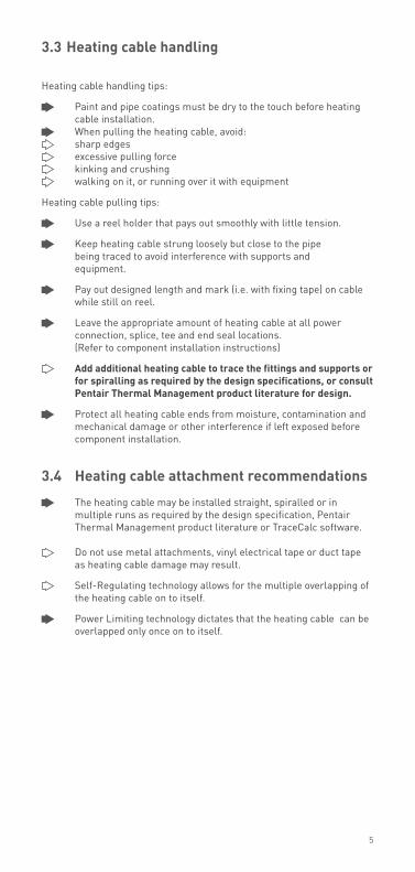
3.3 heating cable handling
Heating cable handling tips:
Paint and pipe coatings must be dry to the touch before heating cable installation.
When pulling the heating cable, avoid: sharp edges excessive pulling force kinking and crushing walking on it, or running over it with equipment
Heating cable pulling tips:
Use a reel holder that pays out smoothly with little tension.
Keep heating cable strung loosely but close to the pipe being traced to avoid interference with supports and equipment.
Pay out designed length and mark (i.e. with fixing tape) on cable while still on reel.
Leave the appropriate amount of heating cable at all power connection, splice, tee and end seal locations. (Refer to component installation instructions)
add additional heating cable to trace the fittings and supports or for spiralling as required by the design specifications, or consult Pentair Thermal management product literature for design.
Protect all heating cable ends from moisture, contamination and mechanical damage or other interference if left exposed before component installation.
3.4 heating cable attachment recommendations
The heating cable may be installed straight, spiralled or in multiple runs as required by the design specification, Pentair Thermal Management product literature or TraceCalc software.
Do not use metal attachments, vinyl electrical tape or duct tape as heating cable damage may result.
Self-Regulating technology allows for the multiple overlapping of the heating cable on to itself.
Power Limiting technology dictates that the heating cable can be overlapped only once on to itself.
5
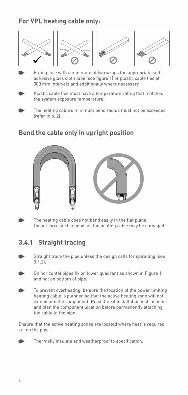
for VPl heating cable only:
Fix in place with a minimum of two wraps the appropriate self-adhesive glass cloth tape (see figure 1) or plastic cable ties at 300 mm intervals and additionally where necessary.
Plastic cable ties must have a temperature rating that matches the system exposure temperature.
The heating cable’s minimum bend radius must not be exceeded (refer to p. 2)
Bend the cable only in upright position
The heating cable does not bend easily in the flat plane. Do not force such a bend, as the heating cable may be damaged.
3.4.1 straight tracing
Straight trace the pipe unless the design calls for spiralling (see 3.4.2).
On horizontal pipes fix on lower quadrant as shown in Figure 1 and not on bottom of pipe.
To prevent overheating, be sure the location of the power limiting heating cable is planned so that the active heating zone will not extend into the component. Read the kit installation instructions and plan the component location before permanently attaching the cable to the pipe.
Ensure that the active heating zones are located where heat is required i.e. on the pipe.
Thermally insulate and weatherproof to specification.
6
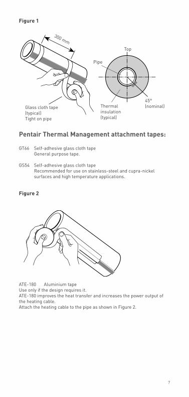
figure 1
Pentair Thermal management attachment tapes:
GT66 Self-adhesive glass cloth tape General purpose tape.
GS54 Self-adhesive glass cloth tape Recommended for use on stainless-steel and cupra-nickel surfaces and high temperature applications.
figure 2
ATE-180 Aluminium tapeUse only if the design requires it. ATE-180 improves the heat transfer and increases the power output of the heating cable. Attach the heating cable to the pipe as shown in Figure 2.
Glass cloth tape (typical)Tight on pipe
Top
Pipe
Thermal insulation (typical)
45° (nominal)
300 mm
7
Glass cloth tape (typical)
Heating cable
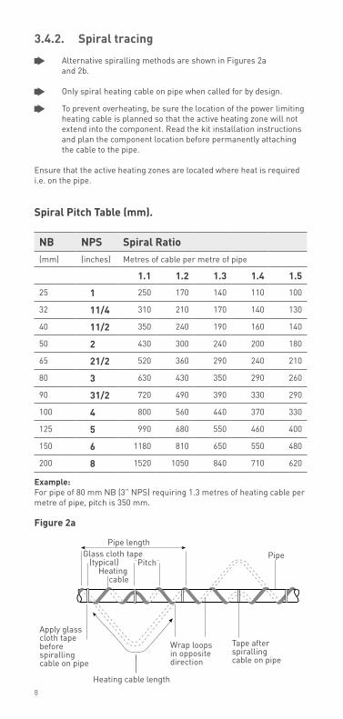
3.4.2. spiral tracing
Alternative spiralling methods are shown in Figures 2a and 2b.
Only spiral heating cable on pipe when called for by design.
To prevent overheating, be sure the location of the power limiting heating cable is planned so that the active heating zone will not extend into the component. Read the kit installation instructions and plan the component location before permanently attaching the cable to the pipe.
Ensure that the active heating zones are located where heat is required i.e. on the pipe.
spiral Pitch Table (mm).
example: For pipe of 80 mm NB (3” NPS) requiring 1.3 metres of heating cable per metre of pipe, pitch is 350 mm.
figure 2a
8
Pipe lengthPipe
Apply glass cloth tape before spiralling cable on pipe
Heating cable length
Wrap loops in opposite direction
Tape after spiralling cable on pipe
Pitch
nB nPs spiral ratio (mm) (inches) Metres of cable per metre of pipe
1.1 1.2 1.3 1.4 1.5
25 1 250 170 140 110 100
32 11/4 310 210 170 140 130
40 11/2 350 240 190 160 140
50 2 430 300 240 200 180
65 21/2 520 360 290 240 210
80 3 630 430 350 290 260
90 31/2 720 490 390 330 290
100 4 800 560 440 370 330
125 5 990 680 550 460 400
150 6 1180 810 650 550 480
200 8 1520 1050 840 710 620
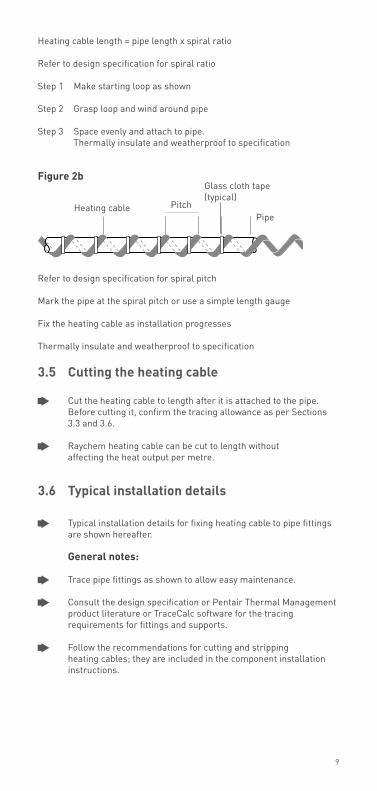
Heating cable length = pipe length x spiral ratio Refer to design specification for spiral ratio
Step 1 Make starting loop as shown
Step 2 Grasp loop and wind around pipe
Step 3 Space evenly and attach to pipe. Thermally insulate and weatherproof to specification
figure 2b
Refer to design specification for spiral pitch
Mark the pipe at the spiral pitch or use a simple length gauge
Fix the heating cable as installation progresses
Thermally insulate and weatherproof to specification
3.5 Cutting the heating cable
Cut the heating cable to length after it is attached to the pipe. Before cutting it, confirm the tracing allowance as per Sections 3.3 and 3.6.
Raychem heating cable can be cut to length without affecting the heat output per metre.
3.6 Typical installation details
Typical installation details for fixing heating cable to pipe fittings are shown hereafter.
general notes:
Trace pipe fittings as shown to allow easy maintenance.
Consult the design specification or Pentair Thermal Management product literature or TraceCalc software for the tracing requirements for fittings and supports.
Follow the recommendations for cutting and stripping heating cables; they are included in the component installation instructions.
9
PipeHeating cable
Glass cloth tape (typical)
Pitch
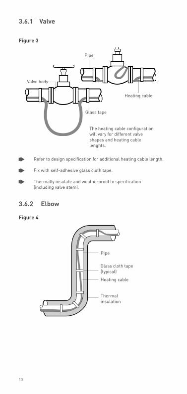
3.6.1 Valve
figure 3
Refer to design specification for additional heating cable length.
Fix with self-adhesive glass cloth tape.
Thermally insulate and weatherproof to specification (including valve stem).
3.6.2 elbow
figure 4
The heating cable configuration will vary for different valve shapes and heating cable lenghts.
Heating cable
Glass tape
Valve body
Pipe
Thermal insulation
Pipe
Glass cloth tape (typical)
Heating cable
10
Glass cloth tape (typical)
Bar hanger
WeatherproofingThermal insulation
Pipe
Heating cableBar hanger
Sealer
Sealer
Heating cable
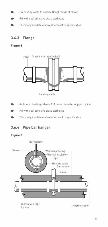
Fix heating cable to outside (long) radius of elbow
Fix with self-adhesive glass cloth tape
Thermally insulate and weatherproof to specification
3.6.3 flange
figure 5
Additional heating cable is 2-3 times diameter of pipe (typical)
Fix with self-adhesive glass cloth pipe
Thermally insulate and weatherproof to specification
3.6.4 Pipe bar hanger
figure 6
Heating cable
Pipe Glass cloth tape(typical)
11
Do not clamp heating cable with support. Heating cable must be over the support
No additional heating cable is required for bar or rod pipe hangers unless called for in the design specification, then use loop length specified
Fix with self-adhesive glass cloth tape
Thermally insulate and weatherproof to specification
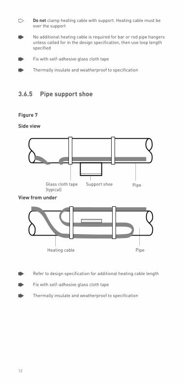
3.6.5 Pipe support shoe
figure 7
side view
View from under
Refer to design specification for additional heating cable length
Fix with self-adhesive glass cloth tape
Thermally insulate and weatherproof to specification
Heating cable Pipe
Support shoeGlass cloth tape (typical)
Pipe
12
4 ComPonenTs insTallaTion
general notes:
Select the required components from Pentair Thermal Management product literature or use the TraceCalc software.
Raychem component kits (including power connections, splices and end seals) must be used to satisfy Standards and Approval Body requirements.
Installation instructions included in the kit must be followed, including those for preparation of the heating cable conductors for connections. Before assembly, use the guide given in the instructions to ensure that the kit is correct for the heating cable and environment.
Raychem self-regulating and power limiting heating cables are parallel circuit design. Do not twist the conductors together as this will result in a short circuit.
4.1 Components required
For the installation of all components refer to the relevant component installation instructions.
Required for each heating cable run: Power connection and insulation entry kit End seal.
As required: Splice Tee-splice: junction box, three connection kits and three insulation entry kits. Accessories (pipe straps, fixing tape, support brackets, labels, etc)
13
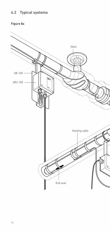
Valve
End seal
Heating cable
JBU-100
SB-100
14
4.2 Typical systems
figure 8a
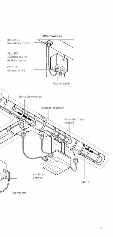
Thermal insulation
Glass cloth tape (typical)
Insulation Entry kit
Splice (as required)
SB-101
Thermostat
C25-100Connection kit
IEK-25-04Insulation entry kit
JBU-100Junction box for modular system
Heating cable
Wallmounted
15

T-100 Tee or splice con nec tion
JBm-100Integrated power/ tee con nec tion
JBs-100Integrated power con nec tion(shown with light)
C-150Low profile power connection
ieK-25-04Insulation entry kit
figure 8b
16

e-100-l Lighted end seal
e-100 End seal
s-150Low profile splice
e-150Low profile end seal
C-150Low profile power connection
17
4.3 Component installation hints
On horizontal pipes locate junction boxes below pipe wherever possible.
Locate junction boxes for easy access but not exposed to
mechanical abuse.
Position junction boxes so that power cable and heating cable entries do not point upwards.
Fix lids in place where access not required.
Confirm junction box stopping plugs are correct for
application and fixed firmly in place.
Route heating cable from junction box to insulation entry so as to avoid possible mechanical damage.
Do not strain heating cable as it exits/enters junction boxes and
insulation entries.
Ensure heating cable is fixed above pipe straps such as used for junction box support brackets.
Fix all low profile components (e.g. heatshrink end seals) in place
with self-adhesive glass cloth tape.
5 ThermosTaTs
In temperature-sensitive applications, thermostatic control may be necessary. If maximum temperature is a concern, consult your Pentair Thermal Management representative for design assistance.
Follow the installation instructions supplied with the thermostat. Use the proper wiring diagram for the heating cable layout and control method desired.
18
19
6 Thermal insulaTion anD marKing
6.1 Pre-insulation checks
Visually inspect the heating cable and components for correct installation and damage. (See Section 10 if damaged.)
Insulation resistance (Megger) testing (as per Section 8) is recommended prior to covering the pipe with thermal insulation.
6.2 insulation installation hints
Correct temperature maintenance requires properly installed and dry thermal insulation.
Thermally insulate and weatherproof to design specification.
Check insulation type and thickness against the design specification.
To minimize potential heating cable damage, insulate as soon as possible after tracing.
Check that all pipework, including fittings, wall penetrations and other areas, have been completely insulated.
Ensure that heating cable is not damaged during installation of cladding for example by drills, self tapping screws and sharp edges of cladding.
Check that all insulation entry kits are fitted correctly and sealed.
Ensure that all places where valve stems, support brackets, thermostat capillaries, etc exit the cladding are sealed.

20
RJ BS-100 -
II 2
G EEx e II
PTB 97 ATEX 1058 U
600
Do not open while energised
Nicht unter Spannung öffnen
Ne pas ouvrir sous tension
BTVEEX de II C
T6
PTB Nr. Ex-95.D.1002 X
EEx e II T6
BAS No. Ex 96D3199X
QTVREEX de II C
T4
PTB Nr. Ex-95.D.1003 X
EEx e II T4
BAS No. Ex 96D3198X
KTVEEX de II C
T2
PTB Nr. Ex-95.D.1004 X
EEx e II 226°C (T2)
BAS No. Ex 96D3200X
4, 8, 12, 15XTV-T3
EEX de II C T3
PTB Nr. Ex-95.D.1005 X
EEx e II T3
BAS No. Ex 96D3435X
20XTV-T2
EEX de II C T2
PTB Nr. Ex-95.D.1005 X
EEx e II 250°C (T2)
BAS No. Ex 95D3435X
PR551647
laB-i-35
laB-i-35
figure 9a
figure 9b
6.3 marking
For power limiting heating cable install label: LAB-I-35 as shown (typical) in figures 9a & 9b
Install “Electric Traced” signs along piping at suitable intervals (3 m intervals recommended) on alternate sides as a warning.
Mark on outside of insulation the location of heating cable components.
7 PoWer suPPly anD eleCTriCal ProTeCTion
7.1 electrical loading
Size overcurrent protective devices according to the design specification or applicable Pentair Thermal Management product literature. If devices other than those specifically identified are used, consult the Pentair Thermal Management representative for the appropriate sizing information.
7.2 residual current (earth fault) protection
Pentair Thermal Management insists on the use of a 30 mA residual current device to provide maximum safety and protection. However, where there is a marked increase in nuisance tripping, a maximum 300 mA residual current device may be used. For heating cables installed in a hazardous area, the use of residual current devices is normally a condition of their approval.
heaTing CaBle TesTing
8.1 recommendations
Pentair Thermal Management recommends insulation resistance test before installing heating cable; before installing thermal insulation; prior to initial start-up; and as part of the periodic maintenance. (see Section 9.2).
8.2 Test method
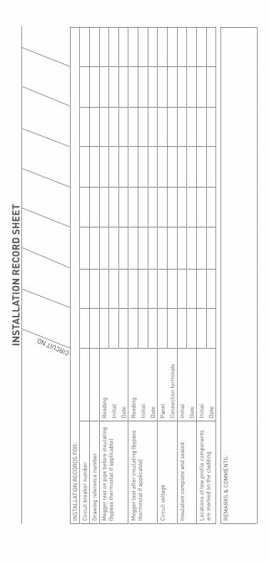
After completing heating cable installation, the insulation resistance between the conductors and the braid should be checked (see Figure 10) using a 2.500 VDC megger. Minimum readings should be 10 Megohms regardless of the heating cable length. The installer should record the original values for each circuit on the installation record sheet (see page 26).
21

figure 10
Test between heating cable and braid
22
9 oPeraTion, mainTenanCe anD PiPe rePairs
9.1 heating cable operation
Temperature exposure must not exceed that specified in Pentair Thermal management product literature. exceeding those limitations will shorten the service life and may permanently damage the heating cable.
Pipe insulation must be complete and dry to maintain the correct temperature.
9.2 inspection and maintenance
Visual inspection: Exposed heating cable and pipe insulation should be checked periodically to make sure that no physical damage has occured.
Meggering: The system should be meggered regularly. When meggering the insulation resistance from the main supply panel, it is recommended that the test is performed between L/N (together) and PE. Freeze protection systems should be meggered before the winter months each year (see section 8). Temperature maintenance systems should be tested at least twice a year. Function testing of electrical protection and temperature control systems should be carried out at regular intervals.
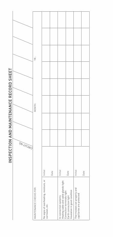
The Periodic Inspection Record on the following pages should be filled out during maintenance of each circuit in your system.
9.3 Piping systems repair and maintenance
Isolate heating cable circuit.
Protect the heating cable from mechanical or thermal damage during pipe repair work.
Check heating cable installation after pipe repairs and restore thermal insulation following the recommendations in Section 6. Check correct functioning of electrical protection systems.
23
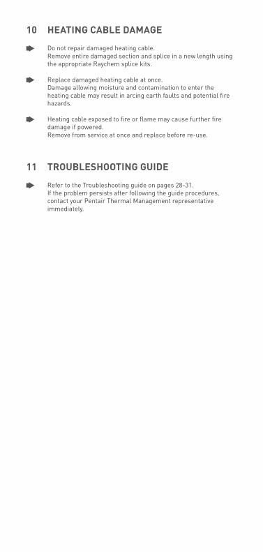
10 heaTing CaBle Damage
Do not repair damaged heating cable. Remove entire damaged section and splice in a new length using the appropriate Raychem splice kits.
Replace damaged heating cable at once. Damage allowing moisture and contamination to enter the heating cable may result in arcing earth faults and potential fire hazards.
Heating cable exposed to fire or flame may cause further fire damage if powered. Remove from service at once and replace before re-use.
11 TrouBleshooTing guiDe
Refer to the Troubleshooting guide on pages 28-31. If the problem persists after following the guide procedures, contact your Pentair Thermal Management representative immediately.
insT
all
aTio
n r
eCo
rD
sh
eeT
CIRCUIT NO.
INST
ALLA
TIO
N R
ECO
RD
S FO
R:
Circ
uit b
reak
er n
umbe
r
Dra
win
g re
fere
nce
num
ber
Meg
ger
test
on
pipe
bef
ore
insu
latin
g (b
ypas
s th
erm
osta
t if a
pplic
able
)R
eadi
ng
Initi
al
Dat
e
Meg
ger
test
afte
r in
sula
ting
(byp
ass
ther
mos
tat i
f app
licab
le)
Rea
ding
Initi
al
Dat
e
Circ
uit v
olta
gePa
nel
Conn
ectio
n te
rmin
als
Insu
latio
n co
mpl
ete
and
seal
edIn
itial
Dat
e
Loca
tions
of l
ow p
rofil
e co
mpo
nent
s ar
e m
arke
d on
the
clad
ding
Initi
al
Dat
e
REM
ARK
S &
CO
MM
ENTS
:
insP
eCTi
on
an
D m
ain
Ten
an
Ce r
eCo
rD
sh
eeT
CIRCUIT NO.
MAI
NTE
NAN
CE C
HEC
KS
FOR
:M
ON
TH:
YR.:
No
sign
s of
ove
rhea
ting,
moi
stur
e, o
r co
rros
ion,
etc
.In
itial
Dat
e
In c
onne
ctio
n sy
stem
s H
eatin
g ca
ble
and
cabl
e gl
ands
tigh
t Co
nnec
tion
term
inal
s tig
htEa
rth
conn
ectio
n tig
htIn
sula
tion
in g
ood
cond
ition
Initi
al
Dat
e
Ther
mos
tats
set
pro
perl
y an
d ca
pilla
ries
are
pro
tect
edIn
itial
Dat
e

Meg
ger
test
(byp
ass
ther
mos
tat i
f ap
plic
able
)R
eadi
ng
Initi
al
Dat
e
Circ
uit v
olta
gePa
nel
Conn
ectio
n te
rmin
als
All b
oxes
and
ther
mos
tats
hav
e be
en
firm
ly c
lose
dIn
itial
Dat
e
Loca
tions
of l
ow p
rofil
e co
mpo
nent
s ar
e m
arke
d on
the
clad
ding
Initi
al
Dat
e
REM
ARK
S &
CO
MM
ENTS
:

Troubleshooting guide
a symptom: overcurrent protection trips or blows Probable Causes
1 Electrical fault at a damaged heating cable b faulty splices or tees c end seal d connection
2 Circuit oversized
3 Start-up below design temperature
4 Defective electrical protection
B symptom: rCD trips Probable Causes
1 Earth fault at: a damaged heating cable b faulty splices or tees c end seal d connection
2 Excessive moisture in: a junction boxes b splices and tees c end seals
3 High leakage currents due to a combination of excessive lengths of power cable and heating cable.
4 Mains borne disturbances
5 Defective RCD
28
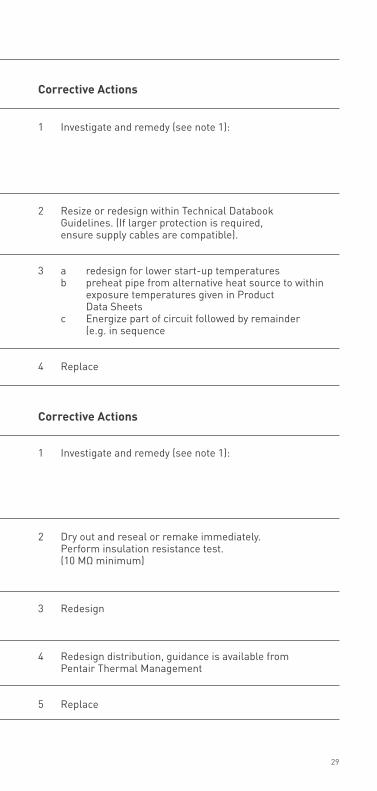
Corrective actions
1 Investigate and remedy (see note 1):
2 Resize or redesign within Technical Databook Guidelines. (If larger protection is required, ensure supply cables are compatible).
3 a redesign for lower start-up temperatures b preheat pipe from alternative heat source to within exposure temperatures given in Product Data Sheets c Energize part of circuit followed by remainder (e.g. in sequence
4 Replace
Corrective actions
1 Investigate and remedy (see note 1):
2 Dry out and reseal or remake immediately. Perform insulation resistance test. (10 MΩ minimum)
3 Redesign
4 Redesign distribution, guidance is available from Pentair Thermal Management
5 Replace
29
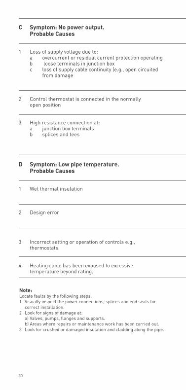
note:Locate faults by the following steps:1 Visually inspect the power connections, splices and end seals for
correct installation.2 Look for signs of damage at: a) Valves, pumps, flanges and supports. b) Areas where repairs or maintenance work has been carried out.3 Look for crushed or damaged insulation and cladding along the pipe.
C symptom: no power output. Probable Causes
1 Loss of supply voltage due to: a overcurrent or residual current protection operating b loose terminals in junction box c loss of supply cable continuity (e.g., open circuited from damage
2 Control thermostat is connected in the normally open position
3 High resistance connection at: a junction box terminals b splices and tees
D symptom: low pipe temperature. Probable Causes
1 Wet thermal insulation
2 Design error
3 Incorrect setting or operation of controls e.g., thermostats.
4 Heating cable has been exposed to excessive temperature beyond rating.
30

4 If after 1, 2 and 3 above the fault has not been located, then either: a) Consult Pentair Thermal Management for futher assistance. b) Where local practices and conditions allow (e.g., non hazardous areas) isolate one section of heating cable from another by cutting in half and testing (e.g., Insulation Resistance) both halves until general area of damage is found. Remove insulation and expose fault.
Corrective actions
1 Restore supply voltage a following a and B (page 31) b re-tighten terminals NB: If excessive heating has occured due to high resistance, replace terminals or crimps c locate damage and repair
2 Reconnect to normally closed position
3 Locate and remedy by: a re-tighten b repair NB: If excessive heating has occured due to high resistance, replace terminals or crimps
Corrective actions
1 Remove and replace with dry insulation of correct specification and ensure complete weatherproofing
2 a check with competent authority for design conditions b modify to meet Pentair Thermal Management recommendations
3 Repair or reset to correct level of operation
4 Replace
31


www.thermal.pentair.com
All Pentair trademarks and logos are owned by Pentair or its global affiliates. Pentair reserves the right to change specifications without prior notice.
© 2013 Pentair All Rights Reserved.
Thermal managemenT soluTionsEN-RaychemSelfRegCable-IM-DOC71 R16
PCN 481825-000
België / BelgiqueTel. +32 16 21 35 02Fax +32 16 21 36 [email protected]
BulgariaTel./fax +359 56 86 68 86fax +359 56 86 68 [email protected]
Česká republikaTel. +420 241 009 215Fax +420 241 009 [email protected]
DanmarkTel. +45 70 11 04 00Fax +45 70 11 04 [email protected]
DeutschlanDTel. 0800 1818205Fax 0800 [email protected]
españaTel. +34 902 125 307Fax +34 91 640 29 [email protected]
FranceTél. 0800 906045Fax 0800 [email protected]
hrvatskaTel. +385 1 605 01 88Fax +385 1 605 01 88 [email protected]
italiaTel. +39 02 577 61 51Fax +39 02 577 61 55 [email protected]
lietuva/latvija/eestiTel. +370 5 2136633Fax +370 5 [email protected]
magyarországTel. +36 1 253 7617Fax +36 1 253 [email protected]
neDerlanDTel. 0800 0224978Fax 0800 [email protected]
norgeTel. +47 66 81 79 90Fax +47 66 80 83 [email protected]
ÖsterreichTel. 0800 297410Fax 0800 [email protected]
polskaTel. +48 22 331 29 50Fax +48 22 331 29 51 [email protected]
repuBlic oF kazakhstanTel. +7 495 926 18 85Fax +7 495 926 18 86 [email protected]
РОССИЯТел. +7 495 926 18 85Факс +7 495 926 18 [email protected]
serBia anD montenegroTel. +381 230 401 770Fax +381 230 401 [email protected]
schweiz / suisseTel. 0800 551308Fax 0800 [email protected]
suomiPuh. 0800 11 67 99Telekopio 0800 11 86 [email protected]
sverigeTel. +46 31 335 58 00Fax +46 31 335 58 [email protected]
türkiyeTel. +90 530 977 64 67Fax +32 16 21 36 [email protected]
uniteD kingDomTel. 0800 969013Fax 0800 [email protected]