installation and maintenance manual clean air module · installation and maintenance manual series...
TRANSCRIPT
LLB3, 4-TFM20GB
Installation and Maintenance ManualSeries LLB3*4Clean Air Module
1 Safety Instructions
• This manual contains essential information for the protection of usersand others from possible injury and/or equipment damage.
• Read this manual before using the product, to ensure correct handling,and read the manuals of related apparatus before use.
• Keep this manual in a safe place for future reference.• These instructions indicate the level of potential hazard by label of
“CAUTION”, “WARNING” or “DANGER”, followed by important safetyinformation which must be carefully followed.
• To ensure safety of personnel and equipment the safety instructions inthis manual and the product catalogue must be observed, along withother relevant safety practices.
• This product is class A equipment that is intended for use in anindustrial environment.
WARNING• The compatibility of pneumatic equipment is the responsibility of
the person who designs the pneumatic system or decides itsspecifications.Since the products specified here can be used in various operatingconditions, their compatibility with the specific pneumatic system mustbe based on specifications or after analysis and/or tests to meetspecific requirements.
• Only trained personnel should operate pneumatically operatedmachinery and equipment.
• Compressed air can be dangerous if an operator is unfamiliar with it.Assembly, handling or repair of pneumatic systems should beperformed by trained and experienced personnel.
• Do not service machinery/equipment or attempt to removecomponents until safety is confirmed.1) Inspection and maintenance of machinery/equipment should only beperformed after confirmation of safe locked-out control positions.2) When equipment is to be removed, confirm the safety process asmentioned above. Switch off air and electrical supplies and exhaust allresidual compressed air in the system.3) Before machinery/equipment is re-started, ensure all safetymeasures to prevent sudden movement of cylinders etc. (Supply air intothe system gradually to create back pressure, i.e. incorporate a soft-start valve).
• Do not use this product outside of the specifications. ContactSMC if it is to be used in any of the following conditions:1) Conditions and environments beyond the given specifications, or ifthe product is to be used outdoors.2) Installations in conjunction with atomic energy, railway, air navigation,vehicles, medical equipment, food and beverage, recreation equipment,emergency stop circuits, press applications, or safety equipment.3) An application which has the possibility of having negative effects onpeople, property, or animals, requiring special safety analysis.
CAUTION• Ensure that the air supply system is filtered to 5 microns.
2 Specifications
2.1 General Specifications
Clean Air Module Common Specifications
Note 1) Inlet air conditions: Equivalent to ISO 8573-1 and Quality Class1.4.1-1.6.1.
Note 2) The guaranteed display of digital flow switch ranges between 15 to35°C.
Note 3) The maximum flow rate varies depending on set pressure. Refer to'Flow Characteristics' for detail.
Note 4) According to SMC measurement conditions.
Table 1
Digital Flow Switch Unit Specifications
2 Specifications (Continued)
Table 2
Figure 1
Table 3
Regulator Unit Specifications
Table 4
ON/OFF Valve Unit Specifications
Table 5
Restrictor Unit Specifications
Table 6
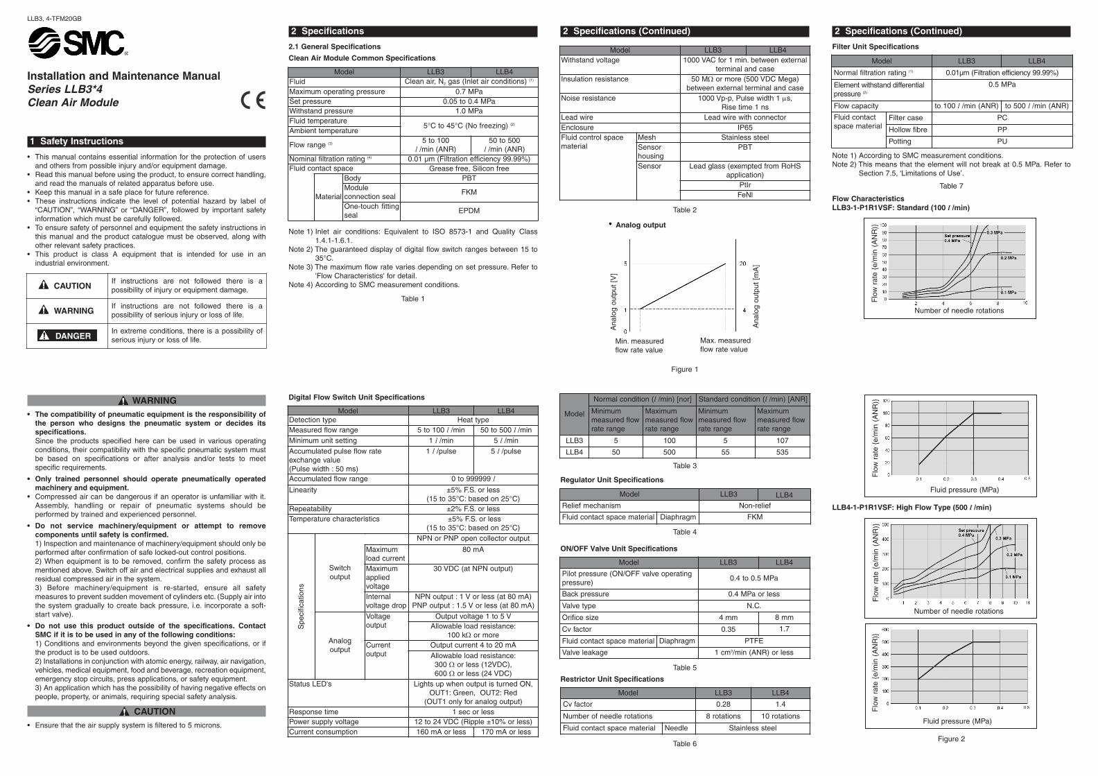
LLB4-1-P1R1VSF: High Flow Type (500 l /min)
Figure 2
2 Specifications (Continued)
Filter Unit Specifications
Note 1) According to SMC measurement conditions.Note 2) This means that the element will not break at 0.5 MPa. Refer to
Section 7.5, ‘Limitations of Use’.
Table 7
Flow CharacteristicsLLB3-1-P1R1VSF: Standard (100 l /min)
CAUTIONIf instructions are not followed there is apossibility of injury or equipment damage.
WARNINGIf instructions are not followed there is apossibility of serious injury or loss of life.
In extreme conditions, there is a possibility ofserious injury or loss of life.DANGER
Model LLB3 LLB4Fluid Clean air, N2 gas (Inlet air conditions) (1)
Maximum operating pressure 0.7 MPaSet pressure 0.05 to 0.4 MPaWithstand pressure 1.0 MPaFluid temperature
5°C to 45°C (No freezing) (2)
Ambient temperature
Flow range (3) 5 to 100l /min (ANR)
50 to 500l /min (ANR)
Nominal filtration rating (4) 0.01 µm (Filtration efficiency 99.99%)Fluid contact space Grease free, Silicon free
Material
Body PBTModuleconnection seal
FKM
One-touch fittingseal
EPDM
Model LLB3 LLB4Detection type Heat typeMeasured flow range 5 to 100 l /min 50 to 500 l /minMinimum unit setting 1 l /min 5 l /minAccumulated pulse flow rateexchange value(Pulse width : 50 ms)
1 l /pulse 5 l /pulse
Accumulated flow range 0 to 999999 lLinearity ±5% F.S. or less
(15 to 35°C: based on 25°C)Repeatability ±2% F.S. or lessTemperature characteristics ±5% F.S. or less
(15 to 35°C: based on 25°C)
Spe
cific
atio
ns
Switch output
NPN or PNP open collector output
Maximumload current
80 mA
Maximumappliedvoltage
30 VDC (at NPN output)
Internalvoltage drop
NPN output : 1 V or less (at 80 mA)PNP output : 1.5 V or less (at 80 mA)
Analog output
Voltageoutput
Output voltage 1 to 5 VAllowable load resistance:
100 kΩ or moreCurrentoutput
Output current 4 to 20 mAAllowable load resistance:300 Ω or less (12VDC), 600 Ω or less (24 VDC)
Status LED's Lights up when output is turned ON,OUT1: Green, OUT2: Red
(OUT1 only for analog output)Response time 1 sec or lessPower supply voltage 12 to 24 VDC (Ripple ±10% or less)Current consumption 160 mA or less 170 mA or less
Model LLB3 LLB4Withstand voltage 1000 VAC for 1 min. between external
terminal and caseInsulation resistance 50 MΩ or more (500 VDC Mega)
between external terminal and caseNoise resistance 1000 Vp-p, Pulse width 1 μs,
Rise time 1 nsLead wire Lead wire with connectorEnclosure IP65Fluid control spacematerial
Mesh Stainless steelSensorhousing
PBT
Sensor Lead glass (exempted from RoHSapplication)
PtIrFeNl
Model
Normal condition (l /min) [nor] Standard condition (l /min) [ANR]
Minimummeasured flowrate range
Maximummeasured flowrate range
Minimummeasured flowrate range
Maximummeasured flowrate range
LLB3 5 100 5 107
LLB4 50 500 55 535
Model LLB3 LLB4Relief mechanism Non-relief
Fluid contact space material Diaphragm FKM
Model LLB3 LLB4
Pilot pressure (ON/OFF valve operatingpressure)
0.4 to 0.5 MPa
Back pressure 0.4 MPa or less
Valve type N.C.
Orifice size 4 mm 8 mm
Cv factor 0.35 1.7
Fluid contact space material Diaphragm PTFE
Valve leakage 1 cm3/min (ANR) or less
Model LLB3 LLB4
Normal filtration rating (1) 0.01µm (Filtration efficiency 99.99%)
Element withstand differentialpressure (2)
0.5 MPa
Flow capacity to 100 l /min (ANR) to 500 l /min (ANR)
Fluid contactspace material
Filter case PC
Hollow fibre PP
Potting PU
Analog output
Ana
log
outp
ut [
V]
Ana
log
outp
ut [
mA
]
Min. measuredflow rate value
Max. measuredflow rate value
Flo
w r
ate
{e/m
in (
AN
R)}
Number of needle rotations
Fluid pressure (MPa)
Flo
w r
ate
{e/m
in (
AN
R)}
Number of needle rotations
Flo
w r
ate
{e/m
in (
AN
R)}
Model LLB3 LLB4
Cv factor 0.28 1.4
Number of needle rotations 8 rotations 10 rotations
Fluid contact space material Needle Stainless steelFluid pressure (MPa)
Flo
w r
ate
{e/m
in (
AN
R)}
2 Specifications (Continued)
• Test conditions.Model: LLB3-1-P1R1VSF and LLB4-1-P1R1VSFSupply pressure: 0.5 MPa.Pressure setting condition and measured position:
Pressure is set by turning the regulator knob with ON/OFF valve turned off.Pressure is measured at the pressure outlet port.
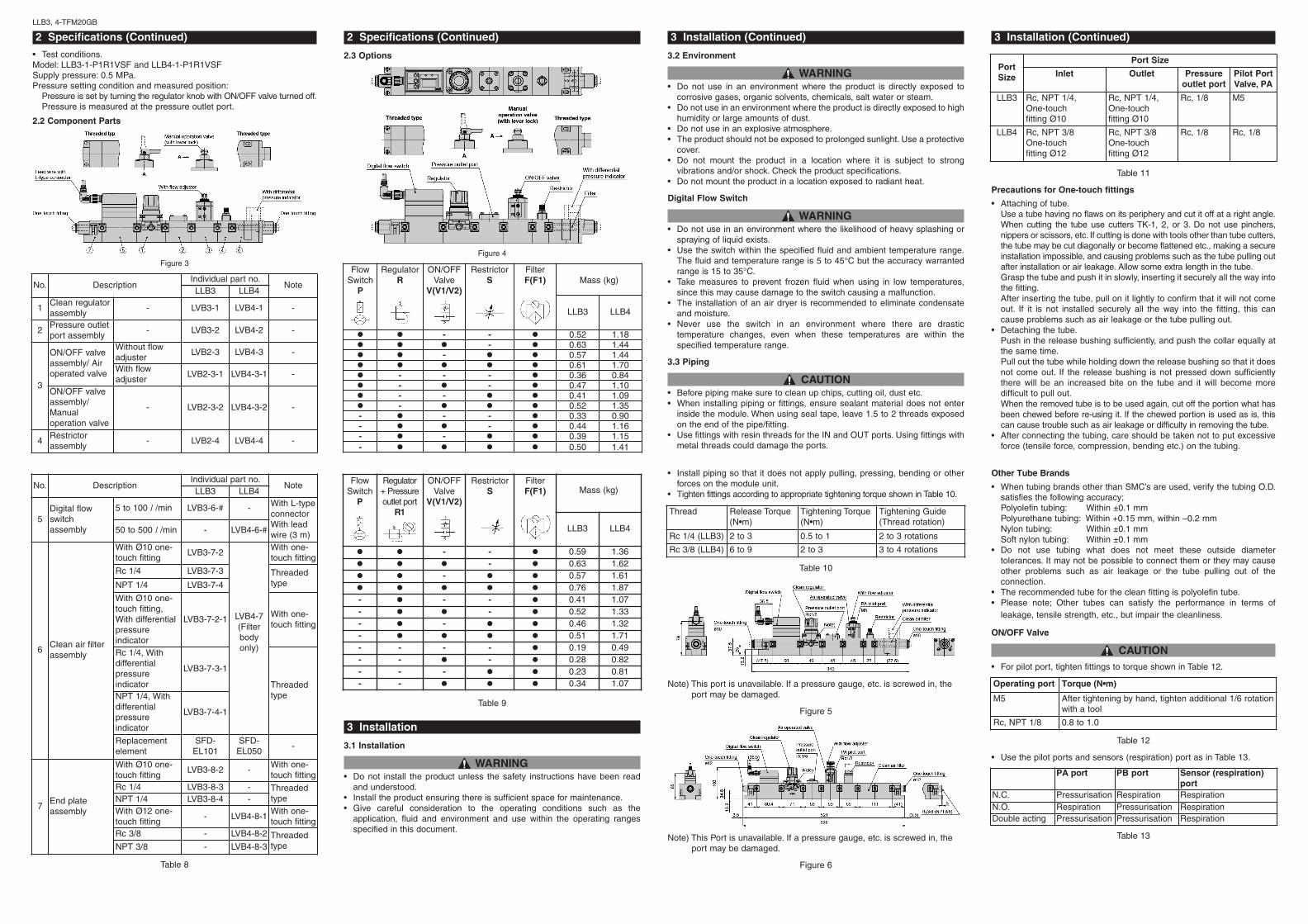
2.2 Component Parts
Figure 3
LLB3, 4-TFM20GB
Table 8
2 Specifications (Continued)
2.3 Options
Figure 4
Table 9
3 Installation
3.1 Installation
WARNING• Do not install the product unless the safety instructions have been read
and understood.• Install the product ensuring there is sufficient space for maintenance.• Give careful consideration to the operating conditions such as the
application, fluid and environment and use within the operating rangesspecified in this document.
3 Installation (Continued)
3.2 Environment
WARNING• Do not use in an environment where the product is directly exposed to
corrosive gases, organic solvents, chemicals, salt water or steam.• Do not use in an environment where the product is directly exposed to high
humidity or large amounts of dust.• Do not use in an explosive atmosphere.• The product should not be exposed to prolonged sunlight. Use a protective
cover.• Do not mount the product in a location where it is subject to strong
vibrations and/or shock. Check the product specifications.• Do not mount the product in a location exposed to radiant heat.
Digital Flow Switch
WARNING• Do not use in an environment where the likelihood of heavy splashing or
spraying of liquid exists.• Use the switch within the specified fluid and ambient temperature range.
The fluid and temperature range is 5 to 45°C but the accuracy warrantedrange is 15 to 35°C.
• Take measures to prevent frozen fluid when using in low temperatures,since this may cause damage to the switch causing a malfunction.
• The installation of an air dryer is recommended to eliminate condensateand moisture.
• Never use the switch in an environment where there are drastictemperature changes, even when these temperatures are within thespecified temperature range.
3.3 Piping
CAUTION• Before piping make sure to clean up chips, cutting oil, dust etc.• When installing piping or fittings, ensure sealant material does not enter
inside the module. When using seal tape, leave 1.5 to 2 threads exposedon the end of the pipe/fitting.
• Use fittings with resin threads for the IN and OUT ports. Using fittings withmetal threads could damage the ports.
• Install piping so that it does not apply pulling, pressing, bending or otherforces on the module unit.
• Tighten fittings according to appropriate tightening torque shown in Table 10.
Table 10
Note) This port is unavailable. If a pressure gauge, etc. is screwed in, theport may be damaged.
Figure 5
Note) This Port is unavailable. If a pressure gauge, etc. is screwed in, theport may be damaged.
Figure 6
Other Tube Brands
• When tubing brands other than SMC’s are used, verify the tubing O.D.satisfies the following accuracy;Polyolefin tubing: Within ±0.1 mmPolyurethane tubing: Within +0.15 mm, within –0.2 mmNylon tubing: Within ±0.1 mmSoft nylon tubing: Within ±0.1 mm
• Do not use tubing what does not meet these outside diametertolerances. It may not be possible to connect them or they may causeother problems such as air leakage or the tube pulling out of theconnection.
• The recommended tube for the clean fitting is polyolefin tube.• Please note; Other tubes can satisfy the performance in terms of
leakage, tensile strength, etc., but impair the cleanliness.
ON/OFF Valve
CAUTION• For pilot port, tighten fittings to torque shown in Table 12.
Table 12
• Use the pilot ports and sensors (respiration) port as in Table 13.
Table 13
3 Installation (Continued)
Table 11
Precautions for One-touch fittings
• Attaching of tube.Use a tube having no flaws on its periphery and cut it off at a right angle.When cutting the tube use cutters TK-1, 2, or 3. Do not use pinchers,nippers or scissors, etc. If cutting is done with tools other than tube cutters,the tube may be cut diagonally or become flattened etc., making a secureinstallation impossible, and causing problems such as the tube pulling outafter installation or air leakage. Allow some extra length in the tube.Grasp the tube and push it in slowly, inserting it securely all the way intothe fitting.After inserting the tube, pull on it lightly to confirm that it will not comeout. If it is not installed securely all the way into the fitting, this cancause problems such as air leakage or the tube pulling out.
• Detaching the tube.Push in the release bushing sufficiently, and push the collar equally atthe same time.Pull out the tube while holding down the release bushing so that it doesnot come out. If the release bushing is not pressed down sufficientlythere will be an increased bite on the tube and it will become moredifficult to pull out.When the removed tube is to be used again, cut off the portion what hasbeen chewed before re-using it. If the chewed portion is used as is, thiscan cause trouble such as air leakage or difficulty in removing the tube.
• After connecting the tubing, care should be taken not to put excessiveforce (tensile force, compression, bending etc.) on the tubing.
Thread Release Torque(N•m)
Tightening Torque(N•m)
Tightening Guide(Thread rotation)
Rc 1/4 (LLB3) 2 to 3 0.5 to 1 2 to 3 rotations
Rc 3/8 (LLB4) 6 to 9 2 to 3 3 to 4 rotations
No. DescriptionIndividual part no.
NoteLLB3 LLB4
5Digital flowswitchassembly
5 to 100 l /min LVB3-6-# - With L-typeconnectorWith leadwire (3 m)50 to 500 l /min - LVB4-6-#
6Clean air filterassembly
With Ø10 one-touch fitting
LVB3-7-2
LVB4-7(Filter body only)
With one-touch fitting
Rc 1/4 LVB3-7-3 ThreadedtypeNPT 1/4 LVB3-7-4
With Ø10 one-touch fitting,With differentialpressureindicator
LVB3-7-2-1With one-touch fitting
Rc 1/4, Withdifferentialpressureindicator
LVB3-7-3-1
ThreadedtypeNPT 1/4, With
differentialpressureindicator
LVB3-7-4-1
Replacementelement
SFD-EL101
SFD-EL050
-
7End plateassembly
With Ø10 one-touch fitting
LVB3-8-2 -With one-touch fitting
Rc 1/4 LVB3-8-3 - ThreadedtypeNPT 1/4 LVB3-8-4 -
With Ø12 one-touch fitting
- LVB4-8-1With one-touch fitting
Rc 3/8 - LVB4-8-2 ThreadedtypeNPT 3/8 - LVB4-8-3
FlowSwitch
P
RegulatorR
ON/OFFValve
V(V1/V2)
RestrictorS
FilterF(F1) Mass (kg)
LLB3 LLB4
- - 0.52 1.18- 0.63 1.44
- 0.57 1.440.61 1.70
- - - 0.36 0.84- - 0.47 1.10- - 0.41 1.09- 0.52 1.35
- - - 0.33 0.90- - 0.44 1.16- - 0.39 1.15- 0.50 1.41
FlowSwitch
P
Regulator+ Pressureoutlet port
R1
ON/OFFValve
V(V1/V2)
RestrictorS
FilterF(F1) Mass (kg)
LLB3 LLB4
- - 0.59 1.36- 0.63 1.62
- 0.57 1.610.76 1.87
- - - 0.41 1.07- - 0.52 1.33- - 0.46 1.32- 0.51 1.71- - - - 0.19 0.49- - - 0.28 0.82- - - 0.23 0.81- - 0.34 1.07
Port Size
Port Size
Inlet Outlet Pressureoutlet port
Pilot PortValve, PA
LLB3 Rc, NPT 1/4,One-touch fitting Ø10
Rc, NPT 1/4,One-touch fitting Ø10
Rc, 1/8 M5
LLB4 Rc, NPT 3/8One-touch fitting Ø12
Rc, NPT 3/8One-touch fitting Ø12
Rc, 1/8 Rc, 1/8
No. DescriptionIndividual part no.
NoteLLB3 LLB4
1Clean regulatorassembly
- LVB3-1 LVB4-1 -
2Pressure outletport assembly
- LVB3-2 LVB4-2 -
3
ON/OFF valveassembly/ Airoperated valve
Without flowadjuster
LVB2-3 LVB4-3 -
With flowadjuster
LVB2-3-1 LVB4-3-1 -
ON/OFF valveassembly/Manualoperation valve
- LVB2-3-2 LVB4-3-2 -
4Restrictorassembly
- LVB2-4 LVB4-4 -
Operating port Torque (N•m)
M5 After tightening by hand, tighten additional 1/6 rotationwith a tool
Rc, NPT 1/8 0.8 to 1.0
PA port PB port Sensor (respiration)port
N.C. Pressurisation Respiration RespirationN.O. Respiration Pressurisation RespirationDouble acting Pressurisation Pressurisation Respiration

3 Installation (Continued)
• For N.C. and N.O. type, the port what is not pressurised should be opento atmosphere. If air intake and exhaust from the valve is not preferabledue to ambient atmosphere or dust, install piping to the valve so thatthe valve can intake/exhaust air at the proper place.
3.4 Electrical connection
Digital flow switch
Figure 7
WARNING• Hold the body of the switch when handling. The tensile strength of the
lead wire with connector is 49N. Applying a greater pulling force cancause a malfunction. When handling, hold the body of the switch, do notdangle it from the wire.
• Verify the colour and terminal number when wiring. Incorrect wiring cancause the switch to be damaged and malfunction. Verify the colour andterminal number in the instruction manual before wiring.
• Avoid repeatedly bending or stretching the lead wire. Repeatedlyapplying bending stress or stretching force to the lead wire will cause itto break.
LLB3, 4-TFM20GB
• Confirm proper insulation of wiring. Make sure there is no faulty wiringinsulation (contact with other circuits, ground fault, improper insulationbetween terminals etc.). Damage may occur due to excess current flowinto a switch.
• Do not wire in conjunction with power lines or high voltage lines. Wireseparately from power lines and high voltage lines, avoid wiring in thesame conduit with these lines. Control circuits including switches maymalfunction due to noise from these other lines.
• Do not allow loads to short circuit. Although switches indicate excesscurrent error if loads are short circuited, all incorrect wiring connections(power supply polarity etc.) cannot be protected. Take precautions toavoid incorrect wiring.
3.5 Mounting
WARNING• If air leakage increases or equipment does not operate properly, stop
operation. After mounting is completed, confirm that is has been donecorrectly by performing a suitable function test.
• Be sure to allow straight pipe length that is minimum 8 times the portsize for the inlet side of the switch.
The clean air modules can be mounted using 4 x M4 screws for the LLB3and 4 x M5 screws for the LLB4.
LLB3
Figure 8
3 Installation (Continued)
LLB4
Figure 9
3.6 Lubrication
CAUTION• SMC products have been lubricated for life at manufacture, and do not
require lubrication in service.• If a lubricant is used in the system, use turbine oil Class 1 (no additive),
ISO VG32. Once lubricant is used in the system, lubrication must becontinued because the original lubricant applied during manufacturing willbe washed away.
4 Setting
Digital Flow SwitchFunctions;
4.1 Flow rate selection display
• Real-time flow rate and accumulated flow rate can be selected. Up to999999 of flow rate value can be accumulated.
• The accumulated flow rate is reset when power is turned off.
4.2 Flow rate conversion
• Normal condition (nor) {0°C, 101.3 kPa, Dry air} or standard condition(ANR) {20°C, 101.3 kPa, 65% RH} can be selected.
4.3 Flow rate confirmation display
• This function allows the accumulated flow rate confirmation when real timeflow rate is selected, and the real-time flow rate confirmation whenaccumulated flow rate is selected.
4.4 Key lock
• This function prevents incorrect operation such as changing the set valueaccidentally.
4.5 Error correction
Table 14
4 Setting (Continued)
4.6 Output types
• Real-time switch output, accumulated switch output or accumulated pulseoutput can be selected as an output type.
Real-time switch output
Note 1) Output mode is set to inverted output when shipped from factory.
Figure 10
Accumulated switch output
Note 1) Output mode is set to inverted output when shipped from factory.
Figure 11
Accumulated pulse output
Note 1) Output mode is set to inverted output when shipped from factory.Note 2) Refer to the specifications of display unit for flow rate value per pulse.
Figure 12
5 Internal Circuit & Wiring
Figure 13
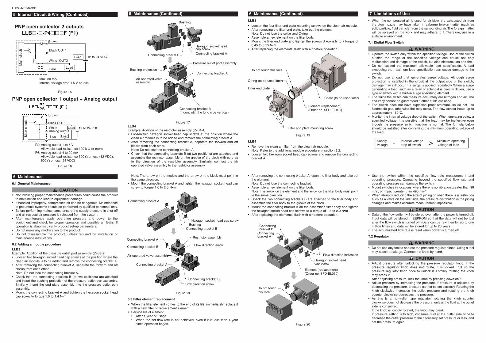
NPN open collector 1 output +Analog output
Figure 14
4 Setting (Continued)
WARNING• Since switch output remains OFF while a message is displayed after
power is turned on, start measurement after value is displayed.• Perform settings after stopping control systems. When the switch’s
initial setting and flow rate setting are performed, output maintains thecondition prior to the settings.
• Do not apply excessive rotational force to the display unit. Theintegrated type display unit can rotate 360°. Rotation is controlled by thestopper: however the stopper may be damaged if the display unit isturned with excessive force.
• Be certain to turn on the power when the flow rate is at zero. Allow aninterval of 10 minutes after turning on the power, as there are somechanges in the display.
• Flow rate unit: Switch measures mass flow rates without beinginfluenced by temperature and pressure. The switches use l /min as theflow rate indicator unit, in which the volumetric flow is substituted formass flow at 0°C and 101.3 kPa (nor). The volumetric flow rate at 20°C,101.3 kPa, and 65%RH (ANR) can be displayed.
LED display Contents Solution
A current of more than80 mA is flowing toOUT1
Check the load and wiring forOUT1
A current of more than80 mA is flowing toOUT2
Check the load and wiring forOUT2
The setting data haschanged for whateverreasons.
Perform the RESET operationand reset all data again.If the setting does not return tothe factory setting, inspectionneeds to be performed by SMC.
The flow rate is over theflow rate measurementrange.
Reduce the flow rate until it iswithin the flow rate measurementrange, using an adjustment valve.
Pin no. Pin description1 DC (+)
2 Analog output
3 DC (-)
4 OUT1
Connector pin numbers
Mounting hole for 4 x M4
Rc 1/4 (NPT1/4) Rc 1/4 (NPT1/4)
Mounting hole for 4 x M5
Connection part Rc3/8 (NPT3/8)
NPN open collector 2 outputs
Max. 30 V, 80 mAInternal voltage drop 1 V or less
Mai
n ci
rcui
t
BrownBlackOUT1 Load
Load
White OUT2
Blue
12 to 24 VDC
BrownBlackOUT1
White Analog output
Load
LoadBlueDC ( )
12 to 24 VDC
P1: Analog output 1 to 5 VAllowable load resistance 100 kΩ or more
P5: Analog output 4 to 20 mAAllowable load resistance 300 Ω or less (12 VDC),600 Ω or less (24 VDC)
Mai
n ci
rcui
t
5 Internal Circuit & Wiring (Continued)
Figure 15
Figure 16
LLB3, 4-TFM20GB
6 Maintenance
6.1 General Maintenance
CAUTION• Not following proper maintenance procedures could cause the product
to malfunction and lead to equipment damage.• If handled improperly, compressed air can be dangerous. Maintenance
of pneumatic systems should be performed by qualified personnel only.• Before performing maintenance ensure the supply pressure is shut off
and all residual air pressure is released from the system.• After maintenance apply operating pressure and power to the
equipment and check for proper operation and possible air leaks. Ifoperation is abnormal, verify product set-up parameters.
• Do not make any modification to the product.• Do not disassemble the product, unless required by installation or
maintenance instructions.
6.2 Adding a module procedure
LLB3Example: Addition of the pressure outlet port assembly (LVB3-2).• Loosen two hexagon socket head cap screws at the position where the
clean air module is to be added and remove the connecting bracket A.• After removing the connecting bracket A, separate the forward and aft
blocks from each other.Note: Do not lose the connecting bracket A.
• Check that the connecting brackets B (at two positions) are attachedand insert the bushing projection of the pressure outlet port assembly.Similarly, insert the end plate assembly into the pressure outlet portassembly.
• Mount the connecting bracket A and tighten the hexagon socket headcap screw to torque 1.0 to 1.4 N•m
6 Maintenance (Continued)
Figure 17LLB4Example: Addition of the restrictor assembly (LVB4-4).• Loosen two hexagon socket head cap screws at the position where the
clean air module is to be added and remove the connecting bracket A.• After removing the connecting bracket A, separate the forward and aft
blocks from each other.Note: Do not lose the connecting bracket A.
• Check that the connecting brackets B (at two positions) are attached andassemble the restrictor assembly on the groove of the block with care asto the direction of the restrictor assembly. Similarly, connect the airoperated valve assembly to the restrictor assembly.
Note: The arrow on the module and the arrow on the block must point inthe same direction.
• Mount the connecting bracket A and tighten the hexagon socket head capscrew to torque 1.6 to 2.0 N•m
Figure 18
6.3 Filter element replacement
• When the filter element comes to the end of its life, immediately replace itwith a new filter or replacement element.
• Service life of element;• After 1 year of usage.• When the set flow rate is not achieved, even if it is less than 1 year
since operation began.
6 Maintenance (Continued)
LLB3
• Loosen the four filter end plate mounting screws on the clean air module.• After removing the filter end plate, take out the element.
Note: Do not lose the collar and O-ring.• Assemble a new element on the filter body.• Mount the filler end plate and tighten the screws diagonally to a torque of
0.45 to 0.55 N•m• After replacing the elements, flush with air before operation.
Figure 19
LLB4
• Remove the clean air filter from the clean air module.Note: Refer to the additional module procedure in section 6.2.
• Loosen two hexagon socket head cap screws and remove the connectingbracket A.
• After removing the connecting bracket A, open the filter body and take outthe element.Note: Do not lose the connecting bracket.
• Assemble a new element on the filter body.Note: The arrow on the element and the arrow on the filter body must pointin the same direction.
• Check the two connecting brackets B are attached to the filter body andassemble the filter body to the groove of the block.
• Mount the connecting bracket A on the assembled filter body and tightenthe hexagon socket head cap screws to a torque of 1.6 to 2.0 N•m
• After replacing the elements, flush with air before operation.
Figure 20
• Use the switch within the specified flow rate measurement andoperating pressure. Operating beyond the specified flow rate andoperating pressure can damage the switch.
• Mount switches in locations where there is no vibration greater than 98m/s2, or impact greater than 490 m/s2.
• When abruptly reducing the size of piping or when there is a restrictionsuch as a valve on the inlet side, the pressure distribution in the pipingchanges and makes accurate measurement impossible.
CAUTION• Data of the flow switch will be stored even after the power is turned off.
Input data will be stored in EEPROM so that the data will not be lostafter the flow switch is turned off. (Data can be rewritten for up to onemillion times and data will be stored for up to 20 years).
• The accumulated flow rate is reset when power is turned off.
7.2 Regulator
WARNING• Do not use any tool to operate the pressure regulator knob. Using a tool
may cause breakage. Operate the knob by hand.
CAUTION• Adjust pressure after unlocking the pressure regulator knob. If the
pressure regulator knob does not rotate, it is locked. Pull up thepressure regulator knob once to unlock it. Forcibly rotating the knobmay break it.After adjusting pressure, lock the knob by pressing down on it.
• Adjust pressure by increasing the pressure. If pressure is adjusted bydecreasing the pressure, pressure cannot be set correctly. Rotating theknob clockwise increases the outlet pressure and rotating the knobcounter clockwise decreases the pressure.
• As this is a non-relief type regulator, rotating the knob counterclockwise does not decrease the pressure, unless the fluid at the outletside is consumed.If the knob is forcibly rotated, the knob may break.If pressure setting is to high, consume fluid at the outlet side once todecrease the outlet pressure to the necessary set pressure or less, andset the pressure again.
7 Limitations of Use
• When the compressed air is used for air blow, the exhausted air fromthe blow nozzle may have taken in airborne foreign matter (such assolid particle, fluid particle) from the surrounding air. The foreign matterwill be sprayed on the work and may adhere to it. Therefore, use in asuitable environment.
7.1 Digital Flow Switch
WARNING• Operate the switch only within the specified voltage. Use of the switch
outside the range of the specified voltage can cause not onlymalfunction and damage of the switch, but also electrocution and fire.
• Do not exceed the maximum allowable load specification. A loadexceeding the maximum load specification can cause damage to theswitch.
• Do not use a load that generates surge voltage. Although surgeprotection is installed in the circuit at the output side of the switch,damage may still occur if a surge is applied repeatedly. When a surgegenerating a load, such as a relay or solenoid is directly driven, use atype of switch with a built-in surge absorbing element.
• The fluids the switch can measure accurately are nitrogen and air. Theaccuracy cannot be guaranteed if other fluids are used.
• The switch does not have explosion proof structure, so do not useflammable gas, otherwise fire may occur. The flow sensor heats up toapproximately 150°C.
• Monitor the internal voltage drop of the switch. When operating below aspecified voltage, it is possible that the load may be ineffective eventhough the pressure switch function is normal. The formula belowshould be satisfied after confirming the minimum operating voltage ofthe load.
Supply Internal voltage Minimum operatingVoltage drop of switch voltage of load>-
PNP open collector 2 outputs
Max. 80 mAInternal voltage drop 1.5 V or less
Mai
n ci
rcui
t
Brown
Black OUT1
LoadWhite OUT2
Blue
12 to 24 VDC
Load
Brown
Black OUT1
12 to 24 VDC
Load
PNP open collector 1 output + Analog output
Mai
n ci
rcui
t
P2: Analog output 1 to 5 VAllowable load resistance 100 k Ω or more
P6: Analog output 4 to 20 mAAllowable load resistance 300 Ω or less (12 VDC),600 Ω or less (24 VDC)
Bushing
Connecting bracket B
Hexagon socket head cap screwConnecting bracket A
Connecting bracket A
Pressure outlet port assembly
Connecting bracket B(mount with the long side vertical)
Air operated valve assembly
Connecting bracket A
Hexagon socket head cap screwBushing
Connecting bracket B
Restrictor assembly
Flow direction arrow
Connecting bracket A
Connecting bracket B
Air operated valve assembly
Connecting bracket A
Connecting bracket B
Flow direction arrow
Do not touch this face
O-ring (to be used later)
Filter end plate
Collar (to be used later)
Element (replacement)(Order no. SFD-EL101)
Filter end plate mounting screw
Connecting bracket B
Connecting bracket A
Flow direction indication
Hexagon socket head cap screw
Element (replacement)(Order no. SFD-EL050)
Do not touch this face.
White Analog output
Blue
Load
Bushing projection

7 Limitations of Use (Continued)
CAUTION• Check the inlet pressure. The setting of the outlet pressure should be
85% or less of the inlet pressure. If the inlet pressure is low, pressurecannot be set correctly.
• Do not operate with fluid what contains solid matter, otherwise, this maycause malfunction.
• Oscillation (beat) may occur with some operating conditions, even if theoperation is within specification. Contact SMC if that is the case.
7.3 ON/OFF Valve
WARNING• The maximum operating pressure and back pressure must be within
the specified range.
CAUTION• Valve leakage is 1 cm3/min or less (at pneumatic pressure), as shipped
from factory.• Product with flow adjuster can cause oscillation with some operating
conditions if operating flow rate is small, so check the flow rate,pressure and piping conditions carefully before operating.
• For flow adjustment with flow adjuster, adjust the flow rate by openingthe knob gradually from the fully closed state.Turning the adjusting knob counter clockwise opens the valve. Do notapply excessive force to the knob around the fully open or fully closedstate, otherwise the orifice seat can be deformed or the adjusting screwknob can be broken. It is shipped from the factory fully closed.
• Have a trial run before operation if the valve has not been used for longperiods of time.
• Pay attention to the lever operating direction and handling of the lever.
LLB3, 4-TFM20GB
7.4 Restrictor
WARNING• Restrictor cannot be used as a stop valve, which requires zero leakage.
There will be some leakage.• Check the number of rotations of the needle valve. It will not rotate
further because of drop-out prevention. Rotating the needle too muchmay cause damage.
7.5 Filter
WARNING• Air equipment what is mounted on the outlet side may generate dust.
If this is the case, it will be a factor in cleanliness. Examine the positionto install air equipment.
• Set operating flow rate within the specified range;LLB3: 100 l /min (ANR) or lessLLB4: 500 l /min (ANR) or lessIf the operating flow rate is out of the specified range, it will causefunctional deterioration and breakage.
• The filter should be installed in a place where pulsation does not occur.• This product cannot operate compressed air what contains fluids such
as water and oil.• For the air source for this product, install a dryer, mist separator,
micro mist separator, super mist separator, odour removal filter, etc.• Generally, compressed air contains the following particle
contaminants;• Moisture (condensate)• Dust in atmospheric air• Deteriorated oil exhausted from the compressor• Solid foreign matter such as rust from the piping
• Flush the piping with air, for cleaning, before installing product.To decrease the affect of dust from a connection, also flush the pipingwith air before using the product for the first time and when it isreplaced.
8 Contacts
URL http://www.smcworld.com (Global) http://www.smceu.com (Europe)Specifications are subject to change without prior notice from the manufacturer.© SMC Corporation All Rights Reserved.
AUSTRIA (43) 2262 62280 NETHERLANDS (31) 20 531 8888BELGIUM (32) 3 355 1464 NORWAY (47) 67 12 90 20CZECH REP. (420) 541 424 611 POLAND (48) 22 211 9600DENMARK (45) 7025 2900 PORTUGAL (351) 21 471 1880FINLAND (358) 207 513513 SLOVAKIA (421) 2 444 56725FRANCE (33) 1 6476 1000 SLOVENIA (386) 73 885 412GERMANY (49) 6103 4020 SPAIN (34) 945 184 100GREECE (30) 210 271 7265 SWEDEN (46) 8 603 1200HUNGARY (36) 23 511 390 SWITZERLAND (41) 52 396 3131IRELAND (353) 1 403 9000 UNITED KINGDOM (44) 1908 563 888ITALY (39) 02 92711