installation and maintenance instructions - buderus, uk … · · 2011-05-13installation and...
TRANSCRIPT
7209 6700 - 02/2006 GB (EN) For the installer
Please read thoroughly
Installation and maintenance instructions
Gas wall hung Boiler condensing600 - 11S / 19S / 24S / 24C
U122 K

2 Installation and servicing instructions for wall-mounted condensing gas boiler 600 - 11S/19S/24S/24C • 02/2006
Buderus • http://www.buderus-domestic.co.uk Subject to modifications resulting from technical improvements!
Subject to technical modifications!
Constant development efforts may result in changes to illustrations, functional steps and technical data.
Updating the documentation
If you have suggestions for improvement or have found discrepancies, please do not hesitate to contact us.
The boiler meets the basic requirements of the appropriate standards and directives.
Conformity has been substantiated by the proper documents which - together with the declaration of conformity - are filed with the manufacturer.
Installation and maintenance instructions for wall-mounted condensing gas boiler 600 - 11S/19S/24S/24C • 02/2006 3
Subject to modifications resulting from technical improvements! Buderus • http://www.buderus-domestic.co.uk
Contents1 Installation . . . . . . . . . . . . . . . . . . . . . . . . . . . . . . 61.1 Dimensions, connections and assembly . . . . . . . . 61.2 Boiler assembly - exploded view . . . . . . . . . . . . . . 71.3 Flue Installation . . . . . . . . . . . . . . . . . . . . . . . . . . . 91.4 Items supplied with unit . . . . . . . . . . . . . . . . . . . . 111.5 Hanging the boiler . . . . . . . . . . . . . . . . . . . . . . . . 111.6 Water circulation system . . . . . . . . . . . . . . . . . . . 121.7 Pipe connections . . . . . . . . . . . . . . . . . . . . . . . . . 121.8 Flue installation . . . . . . . . . . . . . . . . . . . . . . . . . . 151.9 Electrical connections. . . . . . . . . . . . . . . . . . . . . . 171.10 Wiring Diagram. . . . . . . . . . . . . . . . . . . . . . . . . . . 18
2 Initial start-up . . . . . . . . . . . . . . . . . . . . . . . . . . . 222.1 Preparing the boiler for operation . . . . . . . . . . . . . 22
3 Inspection . . . . . . . . . . . . . . . . . . . . . . . . . . . . . . 303.1 Preparing the heating boiler for inspection . . . . . . 30
4 Maintenance . . . . . . . . . . . . . . . . . . . . . . . . . . . . 314.1 Clean the heat exchanger, burner and condensate
trap . . . . . . . . . . . . . . . . . . . . . . . . . . . . . . . . . . . . 314.2 Flushing out the hot-water heat exchanger . . . . . 35
5 Servicing . . . . . . . . . . . . . . . . . . . . . . . . . . . . . . . 365.1 Operating codes . . . . . . . . . . . . . . . . . . . . . . . . . . 365.2 Fault codes. . . . . . . . . . . . . . . . . . . . . . . . . . . . . . 375.3 Checking and replacing parts . . . . . . . . . . . . . . . . 45
6 Changing to another type of gas . . . . . . . . . . . 59
7 Appendix . . . . . . . . . . . . . . . . . . . . . . . . . . . . . . . 627.1 Technical specifications . . . . . . . . . . . . . . . . . . . . 627.2 Short list of spare parts . . . . . . . . . . . . . . . . . . . . 64
8 Reports . . . . . . . . . . . . . . . . . . . . . . . . . . . . . . . . 658.1 Start-up report . . . . . . . . . . . . . . . . . . . . . . . . . . . 658.2 Inspection and maintenance reports . . . . . . . . . . 66
G. C. Aplliance No. :
Buderus 600 - 11S 41-110-16Buderus 600 - 19S 41-110-17Buderus 600 - 24S 41-110-18Buderus 600 - 24C 47-110-01
PrefaceThese installation and servicing instructions apply to: Buderus wall-mounted condensing gas boilers600 - 11S / 19S / 24S / 24C.
Model C13, C33, C53
Type GB II2H3P 20 mbar, 37 mbar
In this document: NG = 2-G20-20 mbarLPG = 3P-G31-37 mbar
Power rating: 230 VAC, 50 Hz, IPX4D
Fuse rating: 1.25 Ampere slow blow
Important general instructions for use
Only use the boiler in accordance with its designated use and the installation and servicing instructions. Servicing and repair must be carried out by CORGI registered installer. Only use the boiler in combinations and with the accessories and spare parts indicated in the installation and servicing instructions. Other combinations, accessories and consumables may only be used if they are expressly provided for the designated use and if system performance and safety are not affected in any way.
The boiler is suitable for connection to fully pumped, sealed water systems ONLY. Adequate arrangements for completely draining the system by provision of draining valves must be provided in the installation pipework.
Pipework from the boiler is routed downwards as standard, but may be routed upwards behind the boiler using the distance frame (supplied in a separate kit).
Subject to technical modifications.
As a result of our policy of constant development, there may be small differences between illustrations, functional steps and technical data.
BENCHMARK' Log Book
All Buderus gas fired boilers now include an installation, commissioning and service record log book. The details of the log book will be required in the event of any warranty work being requested.Please complete the appropriate sections on completion of the installation and commissioning.
REMEMBER: Please hand the log book back to the user.

4 Installation and maintenance instructions wall-mounted condensing gas boiler 600 - 11S/19S/24S/24C • 02/2006
Buderus • http://www.buderus-domestic.co.uk Subject to modifications resulting from technical improvements!
Regulations and directivesIt is law that all gas appliances are installed and serviced by a CORGI registered installer in accordance with the regulations. Failure to install appliances correctly could lead to prosecution. It is in your own interest, and that of safety, to ensure the law is complied with.
The installation must also be in accordance with the latest I.E.E (BS.7671) Wiring Regulations, water regulations, the building regulations and the Building Standards (Scotland) and any relevant requirements of the local authority.
It is a requirement and in your own interest, and that of safety that this boiler must be installed by a CORGI registered installer, in accordance with the relevant requirements of the current Gas Safety (Installation and Use) Regulations, The Building Regulations, current I.E.E. Wiring Regulations and the relevant British Standard Codes of Practise.
Detailed recommendations are contained in the following British Standard Codes of Practice:
BS. 5440:1 Flues (for gas appliances of rated input not exceeding 70 kW).
BS. 5440:2 Ventilation (for gas appliances of rated input not exceeding 70 kW).
BS. 5449 Forced circulation hot water systems.BS. 5546 Installation of gas hot water supplies for domestic
purposes (2nd. family Gases).BS. 6798 Installation of gas fired hot water boilers of rated
input not exceeding 60 kW.BS. 6891 Low pressure installation pipes.
IGE/UP/1b Tightness testing and purging domestic sized gas installations.
Health and & Safety Document No. 635.
The Electricity at Work Regulations, 1989.
The manufacturer's notes must not be taken, in any way, as overriding statutory obligations.
The design and construction of the Buderus wall-mounted condensing gas boiler 600 - 11S/19S/24S/24C conforms to the basic specifications listed in the European directive governing gas-fired appliances 90/396/EEC, and with respect to EN 625, EN 483 and EN 677.
Timber Framed Buildings
If the boiler is to be fitted in a timber framed building it should be fitted in accordance with the Institute of Gas Engineering document IGE/UP/7:1998.
Bathroom Installations
This appliance is rated IPX4D.
The boiler may be installed in any room or internal space, although particular attention is drawn to the requirements of the current IEE (BS.7671) Wiring Regulations and, in Scotland, the electrical provisions of the building regulations applicable in Scotland, with respect to the installation of the boiler in a room or internal space containing a bath or shower.
If the appliance is to be installed in a room containing a bath or shower then, providing water jets are not going to be used for cleaning purposes (as in communal baths/showers), the appliance can be installed in Zone 3, as detailed in BS.7671.
Compartment Installations
A compartment used to enclose the boiler should be designed and constructed especially for this purpose.
An existing cupboard or compartment may be used, provided that it is modified for the purpose.
In both cases, details of essential features of cupboard/ compartment design, including airing cupboard installation, are to conform to the following:BS 6798 (No cupboard ventilation is required - see 'Air Supply' for details).
It is not necessary to have a purpose-provided air vent in the room or internal space in which the boiler is installed. Neither is it necessary to ventilate a cupboard or compartment in which the boiler is installed, due to the low surface temperatures of the boiler casing during operation; therefore the requirements of BS 6798, Clause 12, and BS 5440:2 may be disregarded.
The position selected for installation MUST allow adequate space for servicing in front of the boiler.
For the minimum clearances required for safety and subsequent service, see the wall mounting template.In addition, sufficient space may be required to allow lifting access to the wall mounting plate.
Wall-mounted condensing gas boilers must only be operated with the combustion air/flue gas systems especially devised and authorised for this type of boiler.
NOTEObserve the corresponding technical rules and the building supervisory and statutory regulations when installing and operating the system.
WARNING!Keep the burner-control unit housing CLOSED when working on water-bearing components.
NOTEIt is mandatory to clean and service the system once a year. This includes an inspection of the entire system to see if it is in full working order. Defects and faults must be eliminated immediately.
NOTEWhen instructions aren’t followed, warranty expires.
Installation and maintenance instructions for wall-mounted condensing gas boiler 600 - 11S/19S/24S/24C • 02/2006 5
Subject to modifications resulting from technical improvements! Buderus • http://www.buderus-domestic.co.uk
Observe the relevant standards, regulations and legislation of the country of final use.
Safe handling of substances
Care should be taken when handling the boiler's insulation, which can cause irritation to the skin.
No asbestos, mercury or CFCs are included in any part of the boiler and its manufacture.
CAUTIONUse this device for its intended purpose only.
DANGER!Notes relating to the heating system water.
Thoroughly flush the system before it is filled with water. Use only untreated water or water treatment product such as Sentinel X100 to fill and top up the system.
When using water treatment, only products suitable for use with Buderus heat exchangers are permitted (e.g. Sentinel X100). Your warranty is at risk if an incorrect water treatment product is used in conjunction with this appliance. For more information, contact Buderus Product Support Department.
It is most important that the correct concentration of the water treatment product is maintained in accordance with the manufacturer's instructions.
If the boiler is used in an existing system any unsuitable additives MUST be removed by thorough cleaning. BS.7593:1992 details the steps necessary to clean a domestic central heating system.
In hard water areas, treatment to prevent lime scale may be necessary - however, the use of artificially softened water is NOT permitted.
Under no circumstances should the boiler be fired before the system has been thoroughly flushed.
Do not use water softened in a salt bedding exchanger.
Do not use inhibitors, anti-freeze or other additives.
The expansion vessel must be of sufficient size.
When oxygen-permeable pipes are used (e. g. for floor heating systems) the system must be separated by means of heat exchangers. Unsuitable heating water promotes sludge formation and corrosion. This may cause malfunctions and damage in the heat exchanger.
NOTE:Notes relating to domestic hot water.
The domestic hot water service must be in accordance with BS 5546 and BS 6700.
The boilers are suitable for connection to most types of washing machine and dishwasher appliances.
When connecting to suitable showers, ensure that:
a. The cold inlet to the boiler is fitted with an approved anti-vacuum or syphon non-return valve.
b. Hot and cold water supplies to the shower are of equal pressure.
Where the water hardness exceeds 150 mg/litre, it is recommended that a proprietary scale reducing device is fitted into the boiler cold supply with the requirements of the local water company.
CAUTIONProvision must be made to accommodate the expansion of DHW contained within the appliance, if a non-return valve is fitted to the DHW inlet, as detailed in BS. 67989: §5.4.3.

Installation1
6 Installation and maintenance instructions for wall-mounted condensing gas boiler 600 - 11S/19S/24S/24C • 02/2006
Buderus • http://www.buderus-domestic.co.uk Subject to modifications resulting from technical improvements!
1 Installation
1.1 Dimensions, connections and assembly
480 mm (19")
240 mm (9½")
Ø100 (4")
Ø60 (2 ")38
370 mm (14½")
185 mm (7¼")
105
mm
(4
")
18
DHW Hot, DHW Cold / 35 mm (1¼")
CH Flow, CH return, GAS / 50 mm (2")
12.5
mm
(½
")
950
mm
(37
½")
850
mm
(33
½")
1.5
mm
(
")
117
845.
5 m
m (
33
")
13
840
mm
(33
")
GA
S
CW
DO
65(2½")
65(2½")
65(2½")
65(2½")
65(2½")
13 m
m (
½")
CH
Flo
w
DH
W H
ot
DH
W C
old
CH
Ret
urn
PR
V
CH Flow = CH flow Ø22 mm compression fittingGAS = Gas connection for 24C: Ø22 mm compression fitting
for 11S/19S/24S: R¾"CH Return = CH return Ø22 mm compression fittingCWDO = Condensate drain G1" OUTSIDEDHW Hot = DHW warm out Ø15 mm compression fittingDHW Cold = DHW cold in Ø15 mm compression fittingPRV = Pressure relief valve R¾" (¾" - ½"-adapter supplied with boiler)
NOTESee wall-mounting template for the necessary clearances.

Installation 1
Installation and maintenance instructions for wall-mounted condensing gas boiler 600 - 11S/19S/24S/24C • 02/2006 7
Subject to modifications resulting from technical improvements! Buderus • http://www.buderus-domestic.co.uk
1.2 Boiler assembly - exploded view
Single unit (11S / 19S / 24S)
Legend1. Flow connection piece
2. Automated air vent
3. Hairpin heat exchanger
4. Flow sensor
5. Clip
6. Flow pipe
7. Clip flow pipe
8. Back part heat exchanger
9. Seal heat exchanger
10. Sealing ring burner
11. Burner
12. Heat exchanger
13. Front panel heat exchanger
14. Sight glass
15. Fastener
16. Ventilation cover
17. Casing
18. Condensate trap
19. Syphon cap with seal
20. Drain pipe condens. trap
21. Syphon
22. Sealing ring
23. Flue gas sensor
24. Sealing ring
25. Flue gas pipe
26. Flue gas pipe seal
27. Condensate collector
28. Lipring
29. Combustion divider
30. Insulation divider
31. Fan
32. Gas/air supply pipe
33. Fan seal
34. Venturi
35. Gas valve
36. Rectifier
37. Suction pipe
38. Gas pipe
39. Concentric adapter
40. Lip ring
41. Adapter clip
42. Bracket
43. Cable duct
40
6080
100
120
C20
0
1
2 3
4
bar
23
1
4
5
6
7
8
9
10
11
1213
14
17
16
15
19
18
2022
23
24
25
28
27
5354
32 31
2629
30
33
3435
36
3738
39
40
27
4128
4243
43
44
43
43
45
46
47
48
49
5051
52
3
5453 5
55
56
57
60
58
59
61
62
63
64
65
66
7
7
7
765
68
67
69
82
83
21
44. Ventilation cover seal
45. Pipe duct
46. Sealing ring
47. Cable harness
48. UBA
49. Power switch
50. Temp-pressure gauge
51. UBA panel
52. 230V cable
53. O-ring
54. O-ring
55. Return pump connection pipe
56. Pump
57. Expansion vessel
58. Expansion vessel pipe
59. Manifold assembly
60. Pressure relief valve
61. Spring set
62. Connection house by-pass
63. Clip by-pass
64. Connection house three-way valve
65. Spring set
66. Connection housing pump
67. Connection housing
68. Clip
69. By-pass pipe
82. Hot surface ignitor
83. Ionisation electrode

Installation1
8 Installation and maintenance instructions for wall-mounted condensing gas boiler 600 - 11S/19S/24S/24C • 02/2006
Buderus • http://www.buderus-domestic.co.uk Subject to modifications resulting from technical improvements!
Combi unit (24C)
Legend1. Flow connection piece2. Automated air vent3. Hairpin heat exchanger4. Flow sensor5. Clip6. Flow pipe7. Clip flow pipe8. Back part heat exchanger9. Seal heat exchanger10. Sealing ring burner11. Burner12. Heat exchanger13. Front panel heat
exchanger14. Sight glass15. Fastener16. Ventilation cover17. Casing18. Condensate trap19. Syphon cap with seal20. Drain pipe condens. trap21. Syphon22. Sealing ring23. Flue gas sensor24. Sealing ring25. Flue gas pipe26. Flue gas pipe seal27. Condensate collector28. Lipring29. Combustion divider30. Insulation divider31. Fan32. Gas/air supply pipe33. Fan seal34. Venturi35. Gas valve36. Rectifier37. Suction pipe38. Gas pipe39. Concentric adapter40. Lip ring41. Adapter clip42. Bracket43. Cable duct44. Ventilation cover seal45. Pipe duct46. Sealing ring47. Cable harness48. UBA49. Power switch50. Temp-pressure gauge
40
6080
100
120
C20
0
1
2 3
4
bar
23
1
4
5
6
7
8
9
10
11
1213
14
17
1615
19
18
2022
23
24
25
28
27
5354
32 31
2629
30
33
3435
36
37
38
39
40
28
4128
424243
43
44
43
43
45
46
47
48
49
5051
52
3
5453
5
55
56
57
60
58
59
6162
63
64
65
66
7
7
7
65
68 69
77
7668
7
7
7
6870
75
67
7
72
71
71
73
71
74
78
80
8179
83
82
84
21
51. UBA panel52. 230V cable53. O-ring54. O-ring55. Return pump connection pipe56. Pump57. Expansion vessel58. Expansion vessel pipe59. Manifold assembly
60. Pressure relief valve61. Spring set62. Connection house by-pass63. Clip by-pass64. Connection house three-way valve65. Spring set66. Connection housing pump67. Connection housing68. Clip
69. By-pass pipe70. DHW pipe (hot)71. Clip72. DHW supply pipe73. Hot water sensor74. Boiler sensor75. Insulation hot water tank76. DHW pipe (cold)77. Flow regulator
78. Three-way valve body79. Three-way valve cartridge80. Three-way valve cover81. Three-way valve head82. Hot surface ignitor83. Ionisation electrode84. Hot water tank
Installation 1
Installation and maintenance instructions for wall-mounted condensing gas boiler 600 - 11S/19S/24S/24C • 02/2006 9
Subject to modifications resulting from technical improvements! Buderus • http://www.buderus-domestic.co.uk
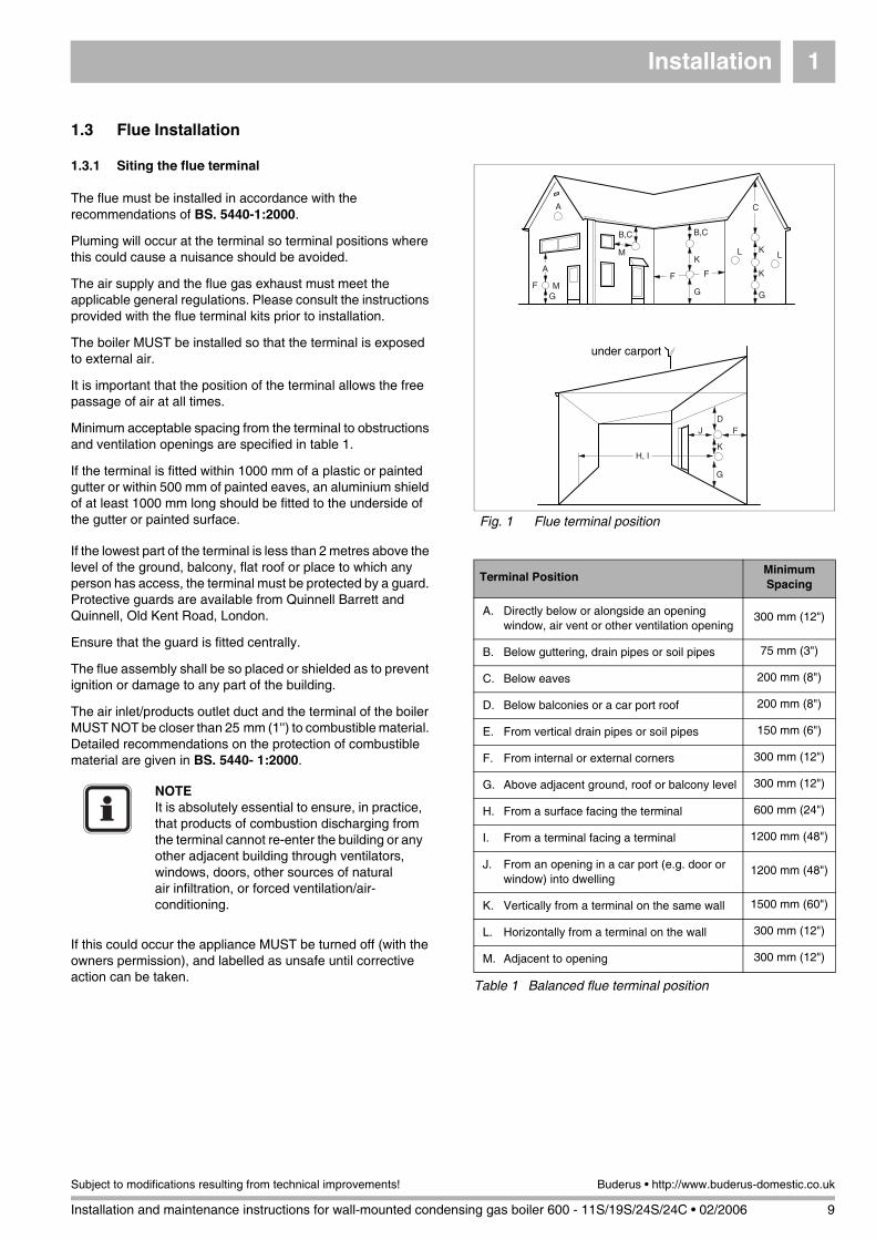
1.3 Flue Installation
1.3.1 Siting the flue terminal
The flue must be installed in accordance with the recommendations of BS. 5440-1:2000.
Pluming will occur at the terminal so terminal positions where this could cause a nuisance should be avoided.
The air supply and the flue gas exhaust must meet the applicable general regulations. Please consult the instructions provided with the flue terminal kits prior to installation.
The boiler MUST be installed so that the terminal is exposed to external air.
It is important that the position of the terminal allows the free passage of air at all times.
Minimum acceptable spacing from the terminal to obstructions and ventilation openings are specified in table 1.
If the terminal is fitted within 1000 mm of a plastic or painted gutter or within 500 mm of painted eaves, an aluminium shield of at least 1000 mm long should be fitted to the underside of the gutter or painted surface.
If the lowest part of the terminal is less than 2 metres above the level of the ground, balcony, flat roof or place to which any person has access, the terminal must be protected by a guard. Protective guards are available from Quinnell Barrett and Quinnell, Old Kent Road, London.
Ensure that the guard is fitted centrally.
The flue assembly shall be so placed or shielded as to prevent ignition or damage to any part of the building.
The air inlet/products outlet duct and the terminal of the boiler MUST NOT be closer than 25 mm (1'') to combustible material. Detailed recommendations on the protection of combustible material are given in BS. 5440- 1:2000.
If this could occur the appliance MUST be turned off (with the owners permission), and labelled as unsafe until corrective action can be taken.
Fig. 1 Flue terminal position
A
A
F MG
M
B,C
F F
B,C
K
G
K
K
G
C
L L
FJ
K
G
D
H, I
under carport
Terminal PositionMinimum Spacing
A. Directly below or alongside an opening window, air vent or other ventilation opening
300 mm (12")
B. Below guttering, drain pipes or soil pipes 75 mm (3")
C. Below eaves 200 mm (8")
D. Below balconies or a car port roof 200 mm (8")
E. From vertical drain pipes or soil pipes 150 mm (6")
F. From internal or external corners 300 mm (12")
G. Above adjacent ground, roof or balcony level 300 mm (12")
H. From a surface facing the terminal 600 mm (24")
I. From a terminal facing a terminal 1200 mm (48")
J. From an opening in a car port (e.g. door or window) into dwelling
1200 mm (48")
K. Vertically from a terminal on the same wall 1500 mm (60")
L. Horizontally from a terminal on the wall 300 mm (12")
M. Adjacent to opening 300 mm (12")
Table 1 Balanced flue terminal position
NOTEIt is absolutely essential to ensure, in practice, that products of combustion discharging from the terminal cannot re-enter the building or any other adjacent building through ventilators, windows, doors, other sources of natural air infiltration, or forced ventilation/air-conditioning.

Installation1
10 Installation and maintenance instructions for wall-mounted condensing gas boiler 600 - 11S/19S/24S/24C • 02/2006
Buderus • http://www.buderus-domestic.co.uk Subject to modifications resulting from technical improvements!
1.3.2 Air supply and flue gas exhaust in a closed installation
A ventilation cover is integrated into the 600 Series condensing gas boilers. This cover houses a number of components, such as the burner and the heat exchanger. Since this ventilation cover is part of the air supply system, it is vital that it is always installed correctly.
To ensure optimal operation, the 600 Series appliances must be connected to a Buderus wall-mounted or roof-mounted flue terminal. These terminals have been developed specifically for the 600 Series condensing gas boilers and have been comprehensively tested. The Buderus wall and roof-mounted flue terminal kits ensure trouble-free operation.
The following items for the flue (see fig. 2) are included in the delivery of the boiler:
– pos. 1: 1 Concentric bend 60/100;
– pos. 2: 1 Horizontal flue terminal 60/100;
– pos. 3: 1 Flue finishing kit.
1.3.3 Maximum Flue length
The maximum pipe length of the air supply and flue gas exhaust pipes for the 600 Series condensing gas boilers (see table 2) is determined by the total pressure loss of all components in the flue gas exhaust / air supply system.
Take the flue conduit clearances into account when planning the layout of the place of installation (see subsection 1.3.1: "Siting the flue terminal" on page 9).
Maximum wall thickness without extensions is 550 mm.Maintain a minimum side wall clearance of 50 mm (see fig. 3).
1.3.4 Additional flue parts
Additional flue parts (see table 3) can be ordered from your supplier.
Fig. 2 Horizontal flue pack
1
2
3
Fig. 3 Side flue and rear flue installation
550 mm
50 mm
L
Flow pressure available for use [Pa]
600 Series 11 S 19 S 24 S 24 C
35 60 100 10
BoilerMaximum
pipe length
For every 90° bend the maximum pipe length has
to be reduced by
600 Series L = 7.5 m 1.2 m
Table 2 Pipe length
Flue parts Order No.
Concentric pipe, 500 mm long, adjustable NE 83703
Concentric pipe, 1000 mm long, not adjustable NE 83704
Concentric bend 90° NE 83705
Concentric bend 45° NE 83706
Table 3 Additional flue parts
Installation 1
Installation and maintenance instructions for wall-mounted condensing gas boiler 600 - 11S/19S/24S/24C • 02/2006 11
Subject to modifications resulting from technical improvements! Buderus • http://www.buderus-domestic.co.uk
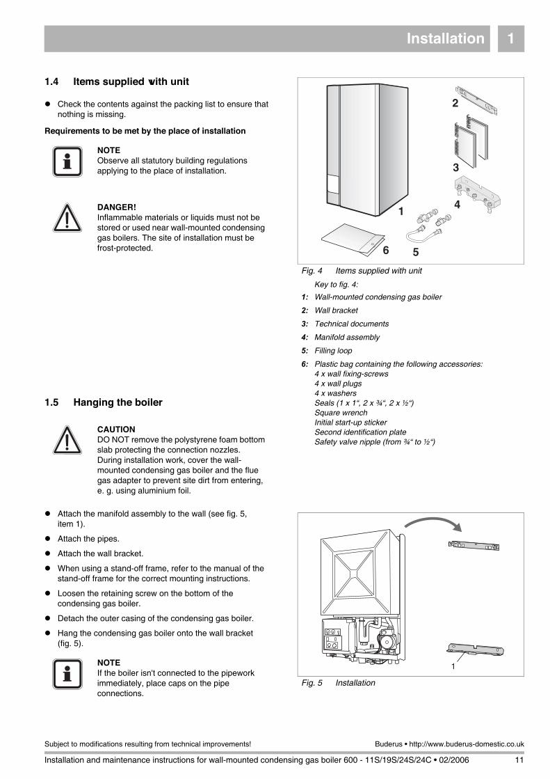
1.4 Items supplied with unit
Check the contents against the packing list to ensure that nothing is missing.
Requirements to be met by the place of installation
1.5 Hanging the boiler
Attach the manifold assembly to the wall (see fig. 5, item 1).
Attach the pipes.
Attach the wall bracket.
When using a stand-off frame, refer to the manual of the stand-off frame for the correct mounting instructions.
Loosen the retaining screw on the bottom of the condensing gas boiler.
Detach the outer casing of the condensing gas boiler.
Hang the condensing gas boiler onto the wall bracket (fig. 5).
Fig. 4 Items supplied with unit
Key to fig. 4:
1: Wall-mounted condensing gas boiler
2: Wall bracket
3: Technical documents
4: Manifold assembly
5: Filling loop
6: Plastic bag containing the following accessories:4 x wall fixing-screws4 x wall plugs4 x washersSeals (1 x 1“, 2 x ¾“, 2 x ½“)Square wrenchInitial start-up stickerSecond identification plateSafety valve nipple (from ¾“ to ½“)
41
2
3
6 5
NOTEObserve all statutory building regulations applying to the place of installation.
DANGER!Inflammable materials or liquids must not be stored or used near wall-mounted condensing gas boilers. The site of installation must be frost-protected.
CAUTIONDO NOT remove the polystyrene foam bottom slab protecting the connection nozzles. During installation work, cover the wall-mounted condensing gas boiler and the flue gas adapter to prevent site dirt from entering, e. g. using aluminium foil.
Fig. 5 Installation
1NOTEIf the boiler isn't connected to the pipework immediately, place caps on the pipe connections.

Installation1
12 Installation and maintenance instructions for wall-mounted condensing gas boiler 600 - 11S/19S/24S/24C • 02/2006
Buderus • http://www.buderus-domestic.co.uk Subject to modifications resulting from technical improvements!
1.6 Water circulation system
The central heating system should be in accordance with BS.6798 and, in addition, for smallbore and microbore systems, BS.5449.
1.7 Pipe connections
Pipework from the boiler is routed downwards as standard, but may be routed upwards behind the boiler using the stand-off frame (supplied in a separate kit).
Connect pipes as shown in fig. 6. Ensure that all pipework is routed so as to minimise any strain on the boiler fittings.
1.7.1 Gas Supply
The gas installation must be installed in accordance with BS6891.
The complete installation MUST be tested for gas tightness and purged as described in IGE/UP/1b.
1.7.2 Gas connection
Connect to gas supply according to relevant standards, installing a screw-threaded gas shutoff valve (accessory) to the gas supply system.
1.7.3 Hot-water temperature for 600 - 24C
Fit a non-shutting diaphragm safety valve (max. 8 bar) upstream of the cold-water inlet. This is not required if the building is equipped with a pressure regulator configured to guarantee that the maximum supply pressure of 10 bar cannot be exceeded.
Connect pipes free of tension (fig. 6).
Fig. 6 Pipe connections
Key to fig. 6:
1: CH flow
2: DHW warm out (combi only)
3: Gas
4: DHW cold in (combi only)
5: CH return
6: Condensate trap
1 2 3 4 5 6
CAUTION!Pipework from the meter to the boiler MUST be of adequate size.
CAUTIONDO NOT use galvanised pipes or fittings. The hot water heat exchanger is made of copper and is liable to suffer the effects of electrolytic corrosion.
NOTEWhen using plastic pipes, observe the supplier’s instructions especially those referring to recommended jointing techniques and the notes relating to the heating system water on page 5.
Installation 1
Installation and maintenance instructions for wall-mounted condensing gas boiler 600 - 11S/19S/24S/24C • 02/2006 13
Subject to modifications resulting from technical improvements! Buderus • http://www.buderus-domestic.co.uk
1.7.4 Condensate drain
A condensate drain is integrated in the boiler. The drain outlet is a standard G1" outside connection. This drain needs to be connected to a drainage point. All pipework and fittings in the condensate drainage system MUST be made of plastic - no other materials may be used.The routing of the drain must be made to allow a minimum fall of 1 in 20 away from the boiler, throughout its length.Excessive external pipe runs should be avoided in order to prevent possible freezing.Any external pipework should be a minimum of 32 mm internal diameter.
Ensure that the condensate trap is filled with water.
1.7.5 Condensate removal
Positioning and termination of the condensate drain pipe
The condensate pipe should be run and terminate internally to the house soil and vent stack or waste pipe. Alternatively, the condensate can be discharged into the rainwater system, or into a purpose-made soak away (condensate absorption point).All connecting drainage pipework should have a fall of at least 2.5° to the horizontal, or approximately 50 mm per metre of pipe run.If the drainage pipe has to be run externally, it is recommended that the pipe be insulated to protect against frost.It should be noted that the connection of a condensate pipe to a drain may be subject to local building controls.
Material for condensate
The condensate drainage pipe should be run in a standard drain pipe material, e.g. PVC (polyvinyl chloride), PVC-U (unplasticized polyvinyl chloride), BS (acrylonitrile-butadienestyrene), PP (polypropylene polyprolene) or PVC-C (cross-linked polyvinyl chloride).
WARNING!Any external run must be insulated.
Installation1
14 Installation and maintenance instructions for wall-mounted condensing gas boiler 600 - 11S/19S/24S/24C • 02/2006
Buderus • http://www.buderus-domestic.co.uk Subject to modifications resulting from technical improvements!
Any internal pipework should be of a diameter to match the requirements of the condensate exit pipe on the appliance.A 32 mm (1¼") waste pipe solvent weld fitting can be used, fitted externally over the condensate exit pipe on the appliance.All external pipework should be kept to a minimum to avoid freezing and should have a diameter of not less than 22 mm.
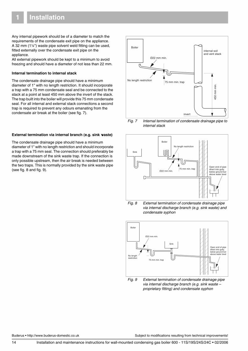
Internal termination to internal stack
The condensate drainage pipe should have a minimum diameter of 1" with no length restriction. It should incorporate a trap with a 75 mm condensate seal and be connected to the stack at a point at least 450 mm above the invert of the stack. The trap built into the boiler will provide this 75 mm condensate seal. For all internal and external stack connections a second trap is required to prevent any odours emanating from the condensate air break at the boiler (see fig. 7).
External termination via internal branch (e.g. sink waste)
The condensate drainage pipe should have a minimum diameter of 1" with no length restriction and should incorporate a trap with a 75 mm seal. The connection should preferably be made downstream of the sink waste trap. If the connection is only possible upstream, then the air break is needed between the two traps. This is normally provided by the sink waste pipe (see fig. 8 and fig. 9).
Fig. 7 Internal termination of condensate drainage pipe to internal stack
No length restriction
Ø22 mm min.
75 mm min. trap
internal soiland vent stack
invert
Boiler
450
mm
min
.
Fig. 8 External termination of condensate drainage pipe via internal discharge branch (e.g. sink waste) and condensate syphon
75 mm min. trap
No length restriction
Ø22 mm min.
Open end of pipedirect into gully,below ground butabove water level
Boiler
Sink
Fig. 9 External termination of condensate drainage pipe via internal discharge branch (e.g. sink waste – proprietary fitting) and condensate syphon
No lengthrestriction
Boiler
Open end of pipedirect into gully,below ground butabove water level
75 mm min. trap
Ø22 mm min.
Sink
Installation 1
Installation and maintenance instructions for wall-mounted condensing gas boiler 600 - 11S/19S/24S/24C • 02/2006 15
Subject to modifications resulting from technical improvements! Buderus • http://www.buderus-domestic.co.uk
Condensate absorption point
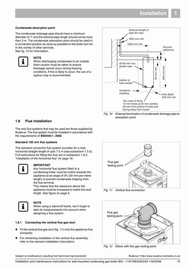
The condensate drainage pipe should have a minimum diameter of 1" and the external pipe length should not be more than 3 m. The condensate absorption point should be sited in a convenient position as close as possible to the boiler but not in the vicinity of other services. See fig. 10 for information.
1.8 Flue installation
The only flue systems that may be used are those supplied by Buderus. The flue system must be installed in accordance with the requirements of BS5440:1. 2000.
Standard 100 mm flue systems
The standard concentric flue system provides for a max. horizontal straight length of upto 7.5 m (see subsection 1.3.3). Full instructions for fitting this flue are in subsection 1.8.2: "Installation of the horizontal flue" on page 16.
1.8.1 Connecting the vertical flue gas duct
Fit the vertical flue gas duct (fig. 11) onto the appliance flue connector.
For remaining installation of the vertical flue assembly, refer to the relevant installation instructions.
Fig. 10 External termination of condensate drainage pipe to absorption point
Ø100 mm min.plastic tube
bottom oftube sealed
limestonecladding hole depth
400 mm min.
300
mm
min
.
25 m
m m
in.
Ground(either/or)
Two rows of three12 mm holes at 25 mm centres50 mm from bottom of tube andfacing away from house
1000 mm min.
Ø22 mm min.
External length ofpipe 3m max.
NOTEWhen discharging condensate to an outside drain caution must be taken to ensure blockage cannot occur during freezing conditions. If this is likely to occur, the use of a syphon trap is recommended.
Fig. 11 Vertical flue connection
Flue gastesting pointIMPORTANT
Any horizontal flue system fitted to a condensing boiler must be incline towards the appliance at an angle of 3% (30 mm per metre length) to prevent condensate dripping from the flue terminal.This means that the clearance above the appliance must be increased to match the duct length. See figure on page 6.
Fig. 12 Elbow with flue gas testing point
Flue gastesting point
NOTEWhen using a stand-off frame, don’t forget to take its measurements into account when designing a flue system.

Installation1
16 Installation and maintenance instructions for wall-mounted condensing gas boiler 600 - 11S/19S/24S/24C • 02/2006
Buderus • http://www.buderus-domestic.co.uk Subject to modifications resulting from technical improvements!
1.8.2 Installation of the horizontal flue
The standard 100 mm diameter horizontal flue system is suitable for lengths upto 560 mm (see fig. 13). For longer flue runs upto 7.5 m, extension air/flue ducts are available (see page 10, table 3).
1.8.3 Flue duct preparation and assembly
Measure the flue length L. Refer to figures 14 and 15.
Mark of the lengths shown onto the ducts and cut the length. The cuts must be square and free from burrs. Terminal assembly outer (air) duct - L-70 mm, inner (flue) duct - L-50 mm. The measurement is made from the ridge at the terminal indicating the outer face of the wall. Refer to figure 16.Extension air duct - L-70 mm, flue duct - L-50 mm.The measurement is from the formed end.
Assemble flue system completely. Push the ducts fully together. The slope of the terminal outlet must be face downwards.The assembly will be made easier if a solvent free grease is lightly applied to the male end of the ducts.
Push the assembly through the wall and slide the turret onto the flue connector. Refer to figure 12.
Ensure that the turret is fully entered into the socket on the boiler. From the outside fix the flue finishing kit to the terminal and, after ensuring the duct is properly inclined towards the boiler, fix the finishing kit to the wall.If the terminal is within 2 m of the ground where there is access then an approved terminal guard must be fitted.The guard must give a clearance of at least 50 mm around the terminal and be fixed with corrosion resistant screws.
Fig. 13 Standard flue
FlueTurret
No Clamp
Maximum 560 mm
Terminalassembly
OuterWall
NOTEUse the wall-mounting template to help you mark the position of the side flue opening
Fig. 14 Flue length - rear
185
L
NOTEThe flue must be inclined to the boiler.
Fig. 15 Flue length - side
L
NOTEAn inner wall sealing plate is provided which should be fitted to the ducts before assembly.
Fig. 16 Flue terminal position
OuterWallFace
Flue Finishing Kit
Flue Terminal
Raised Ringlocating theterminal relativeto the outsidewall face

Installation 1
Installation and maintenance instructions for wall-mounted condensing gas boiler 600 - 11S/19S/24S/24C • 02/2006 17
Subject to modifications resulting from technical improvements! Buderus • http://www.buderus-domestic.co.uk
1.9 Electrical connections
1.9.1 Mains connection
A mains supply of 230 V - 50Hz is required.
External controls are suitable for volt free or 230 V installation.
Wiring to the boiler MUST be in accordance with the current I.E.E. (BS.7671) Wiring Regulations and any local regulations.
Wiring should be a 3 core PVC insulated cable, not less than 0.75 mm2 (24 x 0.2 mm), and to BS.6500 Table 16.
Connection must be made in a way that allows complete isolation of the electrical supply such as a double pole switch having 3 mm (1/8'') contact separation in both poles, or a plug and socket, serving only the boiler and system controls. This boiler is equipped with a double pole switch see fig. 17, item 1.The means of isolation must be accessible to the user after installation.
The electrical connection to the mains supply should be readily accessible and adjacent to the boiler.
If the supply cord is damaged, it must be replaced by a registered Corgi installer to avoid a hazard.
The electrical supply for both the boiler and the system must be taken from the same sparred fused spur outlet.
Fig. 17 UBA
1
Installation1
18 Installation and maintenance instructions for wall-mounted condensing gas boiler 600 - 11S/19S/24S/24C • 02/2006
Buderus • http://www.buderus-domestic.co.uk Subject to modifications resulting from technical improvements!
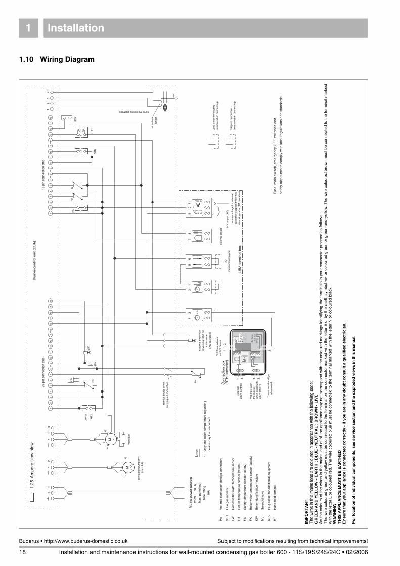
1.10 Wiring Diagram
24 VAC
0 VAC
0
max. 6 VA
hot s
urfa
ceig
nito
r
rem
ove
brid
ge w
hen
carr
ying
out
con
nect
ion
Loop
is n
on-c
ondu
ctin
g(r
emov
e w
hen
conn
ectin
g)
12
MN
L
12
12
34
12
3
MN
L
Bur
ner-
cont
rol u
nit (
UB
A)
12
34
56
78
910
1112
1314
1516
1718
1920
12
34
56
78
910
1112
1314
1516
1718
20-p
in c
onne
ctio
n st
rip18
-pin
con
nect
ion
strip
12
34
56
78
911
10
I/Oco
mm
unic
atio
n po
rt24
V o
utpu
t (A
C)
turn
-on
volta
ge fo
r ex
tern
al,
cust
omer
-sup
plie
d th
ree-
way
reve
rsin
g va
lve
(AC
ope
ratio
n)
exte
rnal
sen
sor
Fus
e, m
ain
switc
h, e
mer
genc
y O
FF
sw
itche
s an
d
safe
ty m
easu
res
to c
ompl
y w
ith lo
cal r
egul
atio
ns a
nd s
tand
ards
circ
ulat
ion
pum
p (P
H)
(max
. 2A
)
ST
B
MV
HT
1H
T2
24V
dc
Ven
tilat
or
PA
FR
FS
exte
rnal
thre
e-w
ayre
vers
ing
valv
e fo
rm
ains
wat
er(A
C o
pera
tion)
FWFK
flame-monitoring electrode
Not
e:
KIM
ST
K
ST
K
PA
V
olt-
free
con
nect
ion
(brid
ge c
onne
ctor
)
ST
B
Flu
e ga
s m
onito
r
FW
D
omes
tic h
ot w
ater
tem
pera
ture
sen
sor
FR
R
etur
n-te
mpe
ratu
re s
enso
r (r
etur
n)
FS
S
afet
y-te
mpe
ratu
re s
enso
r (s
afet
y)
FK
B
oile
r w
ater
-tem
pera
ture
sen
sor
(sup
ply)
KIM
B
oile
r id
entif
icat
ion
mod
ule
MV
S
olen
oid
valv
e
ST
K
Plu
g so
cket
for
addi
tiona
l equ
ipm
ent
HT
H
and-
held
term
inal
1)
Onl
y on
e ro
om-t
empe
ratu
re r
egul
atin
g
de
vice
may
be
conn
ecte
d.
Mai
ns p
ower
sou
rce
230V
~ 5
0 H
z
Max
. per
mitt
ed
fuse
rat
ing
10A
Brid
ge is
con
duct
ive
(rem
ove
whe
n co
nnec
ting)
UB
A te
rmin
al b
ox
1.25
Am
pere
slo
w b
low
21
2112
12
exte
rnal
230V
con
trol
s
Vol
t fre
e ex
tern
alco
ntro
l dev
ice
*) r
emov
e w
irebr
idge
w
hen
used
Vol
t fre
e ro
omth
erm
osta
tw
hen
used
with
230V
tim
er *
)Con
nect
ion
box
(RT
H c
onve
rter
)
1)
IMP
OR
TA
NT
The
wire
s in
this
mai
ns le
ad a
re c
olou
red
in a
ccor
danc
e w
ith th
e fo
llow
ing
code
:G
RE
EN
AN
D Y
EL
LO
W -
EA
RT
H ;
BL
UE
- N
EU
TR
AL
; B
RO
WN
- L
IVE
As
the
colo
urs
of th
e w
ires
in th
e m
ains
lead
of o
f the
app
lianc
e m
ay n
ot c
orre
spon
d w
ith th
e co
lour
ed m
arki
ngs
iden
tifyi
ng th
e te
rmin
als
in y
our
conn
ecto
r pr
ocee
d as
follo
ws:
T
he w
ire c
olou
red
gree
n an
d ye
llow
mus
t be
conn
ecte
d to
the
term
inal
on
the
conn
ecto
r m
arke
d w
ith th
e le
tter
E o
r by
the
eart
h sy
mbo
l o
r co
lour
ed g
reen
or
gree
n-an
d-ye
llow
. The
wire
col
oure
d br
own
mus
t be
conn
ecte
d to
the
term
inal
mar
ked
with
the
lette
r L
or c
olou
red
red.
The
wire
col
oure
d bl
ue m
ust b
e co
nnec
ted
to th
e te
rmin
al m
arke
d w
ith th
e le
tter
N o
r co
lour
ed b
lack
.W
AR
NIN
GT
HIS
AP
PL
IAN
CE
MU
ST
BE
EA
RT
HE
DE
nsu
re t
hat
yo
ur
app
lian
ce is
co
nn
ecte
d c
orr
ectl
y -
if y
ou
are
in a
ny
do
ub
t co
nsu
lt a
qu
alif
ied
ele
ctri
cian
.
Fo
r lo
cati
on
of
ind
ivid
ual
co
mp
on
ents
, see
ser
vice
sec
tio
n a
nd
th
e ex
plo
ded
vie
ws
in t
his
man
ual
.
Installation 1
Installation and maintenance instructions for wall-mounted condensing gas boiler 600 - 11S/19S/24S/24C • 02/2006 19
Subject to modifications resulting from technical improvements! Buderus • http://www.buderus-domestic.co.uk
1.10.1 External controls
The wall-mounted condensing gas boiler can be fitted with the following control devices:
– ON/OFF temperature controller, volt free;
– A room-temperature control device at 230V connected to the connection plate (fig. 20, item 1).
– A modulating room-temperature control device at 24 Volt connected to the connection plate (fig. 22, item 1) such as the 250 RF ModuLink and the iRT controllers.
1.10.2 External 230V controls
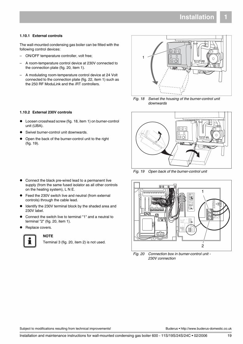
Loosen crosshead screw (fig. 18, item 1) on burner-control unit (UBA).
Swivel burner-control unit downwards.
Open the back of the burner-control unit to the right (fig. 19).
Connect the black pre-wired lead to a permanent live supply (from the same fused isolator as all other controls on the heating system), L N E.
Feed the 230V switch live and neutral (from external controls) through the cable lead.
Identify the 230V terminal block by the shaded area and 230V label.
Connect the switch live to terminal "1" and a neutral to terminal "2" (fig. 20, item 1).
Replace covers.
Fig. 18 Swivel the housing of the burner-control unit downwards
1
Fig. 19 Open back of the burner-control unit
Fig. 20 Connection box in burner-control unit - 230V connection
1
2
NOTE
Terminal 3 (fig. 20, item 2) is not used.
Installation1
20 Installation and maintenance instructions for wall-mounted condensing gas boiler 600 - 11S/19S/24S/24C • 02/2006
Buderus • http://www.buderus-domestic.co.uk Subject to modifications resulting from technical improvements!
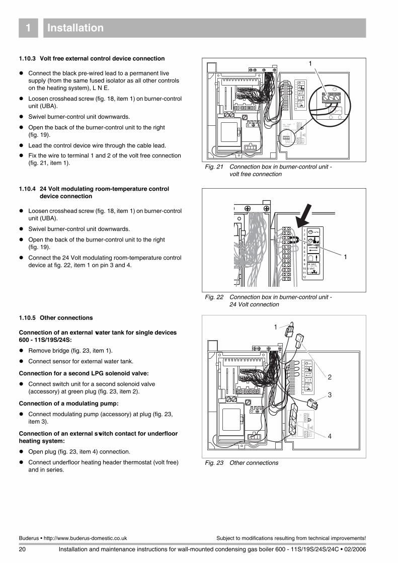
1.10.3 Volt free external control device connection
Connect the black pre-wired lead to a permanent live supply (from the same fused isolator as all other controls on the heating system), L N E.
Loosen crosshead screw (fig. 18, item 1) on burner-control unit (UBA).
Swivel burner-control unit downwards.
Open the back of the burner-control unit to the right (fig. 19).
Lead the control device wire through the cable lead.
Fix the wire to terminal 1 and 2 of the volt free connection (fig. 21, item 1).
1.10.4 24 Volt modulating room-temperature control device connection
Loosen crosshead screw (fig. 18, item 1) on burner-control unit (UBA).
Swivel burner-control unit downwards.
Open the back of the burner-control unit to the right (fig. 19).
Connect the 24 Volt modulating room-temperature control device at fig. 22, item 1 on pin 3 and 4.
1.10.5 Other connections
Connection of an external water tank for single devices 600 - 11S/19S/24S:
Remove bridge (fig. 23, item 1).
Connect sensor for external water tank.
Connection for a second LPG solenoid valve:
Connect switch unit for a second solenoid valve (accessory) at green plug (fig. 23, item 2).
Connection of a modulating pump:
Connect modulating pump (accessory) at plug (fig. 23, item 3).
Connection of an external switch contact for underfloor heating system:
Open plug (fig. 23, item 4) connection.
Connect underfloor heating header thermostat (volt free) and in series.
Fig. 21 Connection box in burner-control unit - volt free connection
1
Fig. 22 Connection box in burner-control unit - 24 Volt connection
1
Fig. 23 Other connections
1
2
3
4

Installation 1
Installation and maintenance instructions for wall-mounted condensing gas boiler 600 - 11S/19S/24S/24C • 02/2006 21
Subject to modifications resulting from technical improvements! Buderus • http://www.buderus-domestic.co.uk
1.10.6 System example
NOTE
Example systems are to be regarded as schematic representations only.
Fig. 24 System example

Initial start-up2
22 Installation and maintenance instructions for wall-mounted condensing gas boiler 600 - 11S/19S/24S/24C • 02/2006
Buderus • http://www.buderus-domestic.co.uk Subject to modifications resulting from technical improvements!
2 Initial start-up
2.1 Preparing the boiler for operation
2.1.1 Fill the heating system
Set three-way valve to the middle setting (applicable for 24C only). This is done by pushing the lever on the three-way valve (fig. 25) with a screwdriver to the middle setting.
If necessary open the CH flow and CH return maintenance valves (fig. 26, item 1 and 2).
Connect temporary hose (fig. 27).
Open both stop valves.
CAUTIONDO NOT operate the condensing gas boiler if large amounts of dust are present, e.g. due to building work in and around the place of installation.
Fig. 25 Three-way valve
WARNINGThe wall-mounted condensing gas boiler must not be activated at this stage.
Fig. 26 Maintenance shutoff valves
CH
Flo
w
CH
Ret
urn
DH
W H
ot(c
ombi
onl
y)
DH
W C
old
(com
bi o
nly)
Gas
1 2
Fig. 27 Connecting temporary hose
temporaryhose
stopvalve
stopvalve
doublecheckvalve
DHWcold
CHreturn

Initial start-up 2
Installation and maintenance instructions for wall-mounted condensing gas boiler 600 - 11S/19S/24S/24C • 02/2006 23
Subject to modifications resulting from technical improvements! Buderus • http://www.buderus-domestic.co.uk
Fill the system to a pressure of 1.0 to 1.2 bar (fig. 28, item 1). Max. water pressure is 1.5 bar.
Shut both stop valves and disconnect the filling loop.
In the case of the 600 - 24C:Purge the hot-water circuit of air
Bleed the hot-water heat exchanger via the vent screw on the heating-circuit side (fig. 29, item 1).
Open the maintenance valve for the cold-water inlet.
Leave the hot water taps open until water begins to flow freely.
To drain the system take the following steps:
Close the DHW cold and the CH return valve.
Connect temporary hose (fig. 30).
Open the CH return stop valve to drain the system.
2.1.2 Checking for leaks
Disconnect the system from the power supply.
Check all sections of gas pipework and connections for signs of leaks before starting up system for the first time.If a leak is detected during tightness testing, use an approved leak detector to check all connections for possible escapes.The product must be certified as a gas leak-testing agent. DO NOT allow the product to come into contact with electrical wiring.
Fig. 28 Pressure display
0
42
bar1
3
20
12060
°C
1 2
10
0 1
11KW
101
1011
I0
1
Fig. 29 Purge the hot-water heat exchanger of air (applies to type 600 - 24C only)
1
Fig. 30 Draining the system
Drain
temporaryhose
Stopvalve
Stopvalve
DH
W C
old
(com
bi o
nly)
CH
Flo
w
CH
Ret
urn
Initial start-up2
24 Installation and maintenance instructions for wall-mounted condensing gas boiler 600 - 11S/19S/24S/24C • 02/2006
Buderus • http://www.buderus-domestic.co.uk Subject to modifications resulting from technical improvements!
2.1.3 Purging air from the gas supply system
Close the gas service valve.
Unscrew the sealing closure of the gas connection-pressure testing nipple by two turns (fig. 31).
Purge system and appliance as per relevant procedures, IGE/UP/1b. Ensuring all safety requirements are met.
Open the gas service valve.
Close the gas shutoff valve once more.
Shut the sealing closure of the test nipple once more.
Open cover for 2nd operating level (fig. 32, item 1).
Start boiler up and move chimney sweep switch (fig. 32, item 3) to position “1”.
The display shows (fig. 32, item 2) “ -.” or “ =.” to indicate that the gas supply system is purged of air. Return chimney sweep switch to normal running position, that is position “0”.
2.1.4 Check combustion air/flue gas connection
Check to ensure that the correct combustion air/flue gas system has been fitted.
Check that the instructions included in the appropriate flue gas system installation manual have been followed.
Fig. 31 Purging air from the gas supply system
Fig. 32 Display and chimney-sweep switch
1 2
10
0 1
11KW
1011
1
2
3
Type of gas Factory settings of gas burners
Natural gas H
When delivered ready for operation and set to Wobbe index 14.1 kWh/m3 (referred to 15 °C, 1013 mbar), applicable for Wobbe index range 11.3 to 15.2 kWh/m3.
Inscription on gas-type indicating label: Category setting:2H G 20_20 mbar
LPG
After adaptation by a CORGI registered installer, the unit can be run on LPG. Inscription on gas-type indicating label: Category setting:3P G 31_37 mbar
Table 4 Gas-supply types

Initial start-up 2
Installation and maintenance instructions for wall-mounted condensing gas boiler 600 - 11S/19S/24S/24C • 02/2006 25
Subject to modifications resulting from technical improvements! Buderus • http://www.buderus-domestic.co.uk
2.1.5 Checking the type of gas and supply
2.1.6 Adjusting the flow temperature
Open the cover to the 2nd operating level (fig. 33, item 1).
Adjust the knob (fig. 33, item 2) to the desired flow temperature (table 6) for your particular installation.
2.1.7 Adjusting the hot-water temperature for 24C only
Adjust the heat-retaining and outlet temperature (table 6) using the hot-water temperature regulator (fig. 33, item 5).
Type of gas supplyGas nozzles ∅ [mm] Venturi
tubes11S 19S/24(C)
Natural gas H (G20) 5.55 6.5Standard Venturi tubes
LPG 3.40 4.15Standard Venturi tubes
Table 5 Gas-nozzle diameter
CAUTIONThe burner must only be put into operation with the correct nozzles (table 5).
NOTEObserve stickers attached to Venturi tubes.
Controllersetting
Flow temperature[°C]
Heat-retaining temperature (only 24 C)
[°C]
Outlet temperature (only 24 C)
[°C]
Hot-water temperature of external tanks
[°C]
1 40 - 60 27
2 44 DO NOT use setting no. 2 31
3 48 40 40 34
4 53 43 43 38
5 58 46 46 41
6 62 49 49 45
7 67 52 52 49
8 71 55 55 52
9 76 58 58 56
10 80 60 60 60
Table 6 Temperature settings
Fig. 33 Control box
Key to Fig. 33:
1: Cover for second operating level
2: Flow temperature knob
3: Heat-capacity jumper
4: Heating capacity knob
5: Hot-water temperature knob
6: Green blocking plate
2
1 2
10
0 1
11KW
1011
3
456
1
NOTEFactory setting of the controller is "10" (around 83 °C).
NOTEFactory setting of the controller is "10".
To avoid energy losses set the controller to setting "1" (fig. 33, item 5). Remove the green blocking plate before making the adjustment.
Initial start-up2
26 Installation and maintenance instructions for wall-mounted condensing gas boiler 600 - 11S/19S/24S/24C • 02/2006
Buderus • http://www.buderus-domestic.co.uk Subject to modifications resulting from technical improvements!
2.1.8 Adjusting the hot-water temperature for external tanks
Use the hot-water temperature regulator to adjust the temperature (fig. 33, item 5) to the desired setting table 6.
2.1.9 Adjust the hot-water flow controller (applies to combi-unit 600 - 24C only)
Adjust the hot-water flow controller (fig. 34) to the desired setting:
– To increase the flow of hot water:turn valve towards “+”.
– To reduce the flow of hot water:turn valve towards “�”.
2.1.10 Setting the heating capacity
Set the heating capacity (table 7), according to the amount of heat required, at the controller (fig. 33, item 4).
Fig. 34 Hot-water flow controller
+NOTEThe unit is factory-adjusted to an output of 22 kW and a flow of 7 l/min
NOTEThe controller is factory-adjusted to position “6”
Controller settingHeating capacity [kW] (±5 %)
600 - 11 S 600 - 19 S 600 - 24 S 600 - 24 C
1 4.9 9.7 9.7 9.7
2 5.6 10.7 11.3 11.3
3 6.3 11.8 12.9 12.9
4 6.9 12.8 14.5 14.5
5 7.6 13.8 16.0 16.0
6 8.3 14.9 17.6 17.6
7 9.0 15.9 19.2 19.2
8 9.6 16.9 20.8 20.8
9 10.3 18.0 22.4 22.4
10 11.0 19.0 24.0 24.0
Table 7 Heating capacity

Initial start-up 2
Installation and maintenance instructions for wall-mounted condensing gas boiler 600 - 11S/19S/24S/24C • 02/2006 27
Subject to modifications resulting from technical improvements! Buderus • http://www.buderus-domestic.co.uk
2.1.11 Measure gas-supply pressure (flow pressure)
Open at least one radiator thermostat valve.
Turn the chimney-sweep switch (fig. 35, item 4) to position “1”.
Loosen the screw plug on the gas test nipple (fig. 36) by two turns.
Attach the pressure-gauge connection hose to the gas test nipple (fig. 37).
Slowly open the gas shutoff valve.
Turn the power switch (fig. 35, item 2) to position “I”. The burner should ignite after about 30 seconds.
Measure the gas connection pressure and note it down on the report form.
The gas-connection pressure must be:for natural gas H min. 17 mbar, max. 25 mbar, nominal connection pressure 20 mbarfor LPG min. 30 mbar, max. 50 mbar, nominal connection pressure 37 mbar.
Detach the gauge-connection tube once more and close the test nipple at the screw plug.
Ensure that switch is returned to "0" after this task has been carried out.
.
Ensure all disturbed joints and connections are checked for gas tightness on completion of tasks.
2.1.12 Check the gas/air ratio and adjust as required
Turn mains power switch (fig. 35, item 2) and chimney-sweep switch (fig. 35, item 4) to “0”.
Unscrew the sealing closure of the burner-pressure testing nipple by one turn (fig. 36).
Connect the positive port of the pressure gauge with a hose to the burner pressure measuring nipple (fig. 37).
Turn mains power switch to “I” and chimney-sweep switch to “1”.
If the burner has fired after approx. 30 seconds, keep the service button (fig. 35, item 3) pressed until “Y” appears on the display.
Turn the hot-water temperature controller (fig. 35, item 1) to “1”.
Read the differential pressure. The differential pressure (pGAS – pAIR) should total -5 Pa (±5 Pa) (display on measuring gauge: -10 Pa to 0 Pa).
Fig. 35 Mains switch, service button and chimney-sweep switch
1 2
10
0 1
11KW
1011
1
3
4
2
CAUTIONThe condensing gas boiler must not be activated at this stage.
Fig. 36 Measure the gas connection pressure
NOTEIf the required connection pressure is not available or too high, contact your gas supplier or TRANSCO.
Fig. 37 Check the gas/air ratio
Initial start-up2
28 Installation and maintenance instructions for wall-mounted condensing gas boiler 600 - 11S/19S/24S/24C • 02/2006
Buderus • http://www.buderus-domestic.co.uk Subject to modifications resulting from technical improvements!
If the gas/air ratio does not conform to specifications, readjust at the setscrew (fig. 37, item 1).
Turn mains power switch and chimney-sweep switch to “0”.
Remove the measuring equipment and retighten the screw in the burner-pressure measuring nipple.
Readjust the hot-water temperature controller to its original setting.
Turn the mains power switch to “I”.
2.1.13 Gas rating test
Isolate all other appliances.
Set the boiler to maximum firing rate.
Ensure that there is no modulating of the fan gas valve.
Carry out the Gas Rating procedure as described in "Essential Gas Safety' 3rd edition on pages 169-176.
2.1.14 Record readings
Unscrew the corresponding sealing closure (fig. 38) on the connection adapter for the combustion-air/flue-gas system and replace it once the measuring operation in question has been carried out.
Carbon monoxide content
2.1.15 Function testing
Measuring the ionisation current (fig. 39)
Disconnect the system from the power supply.
Loosen the plug-and-socket connector of the ionisation electrode and connect the multimeter in series. On the measuring device, select the µ-direct current range. The measuring device must have a resolution of at least 1 µA.
Reconnect the system to the power supply and turn the chimney-sweep switch to “1”.
Measuring the ionisation current. The ionisation current being checked must measure >2 µA direct current.
Enter the reading on the report form.
Disconnect the system from the power supply.
Fig. 38 Measuring points on exhaust conduit
Key to Fig. 38:
1: Exhaust-fume temperature, CO2, CO, NOx
2: Combustion-air temperature
1 2CAUTIONThe carbon monoxide values under vacuum must be smaller than 400 ppm or 0.04 Vol%. Values around or exceeding 400 ppm indicate a faulty burner adjustment, a dirty gas burner or heat exchanger, or a defective burner. Ensure that the cause of the fault is remedied immediately.
NOTEDuring initial start-up and annual servicing, make sure that all control, regulating and safety devices are in full working order and, if applicable, check for correct adjustment.
Fig. 39 Measuring the ionisation current
Initial start-up 2
Installation and maintenance instructions for wall-mounted condensing gas boiler 600 - 11S/19S/24S/24C • 02/2006 29
Subject to modifications resulting from technical improvements! Buderus • http://www.buderus-domestic.co.uk
Remove multimeter and restore the plug-and-socket connection to its original state.
Turn the chimney sweep switch to position “0”.
Reconnect the system to the power supply.When the display shows “7” and the service button is pressed, the display turns to “c”. Press the Reset button. The display shows “r”.
2.1.16 Handing over
After completing the installation and commissioning of the system the installer should hand over to the householder by the following actions:
Hand the User Manual to the householder and explain his/her responsibilities under the relevant national regulations.
Explain and demonstrate the lighting and shutting down procedures.
The operation of the boiler and the use and adjustment of all system controls should be fully explained to the householder, to ensure the greatest possible fuel economy consistent with the household requirements of heating. Advise the User of the precautions necessary to prevent damage to the system and to the building in the event of the system remaining inoperative during frosty conditions.
Explain the function and the use of the boiler heating controls.
Explain the function of the boiler fault mode. Emphasise that if a fault is indicated, the boiler should be turned off and a registered local heating installer consulted.
Explain and demonstrate the function of time and temperature controls, radiator valves etc., for the economic use of the system.
Loss of system water pressure
Explain that the dial on the control panel indicates the central heating system pressure and that if the normal COLD pressure of the system is seen to decrease over a period of time then the systems needs to be topped up. If the pressure decreases frequently than a registered local heating installer should be consulted.
After installation, commissioning and customer handover instructions please complete the BENCHMARK appliance log book and leave this with the customer.
IMPORTANTA comprehensive service should be carried out annually. Stress the importance of regular servicing by a Corgi registered installer.
WARNINGDo not fire the boiler if the pressure has reduced to zero from the original setting.

Inspection3
30 Installation and maintenance instructions for wall-mounted condensing gas boiler 600 - 11S/19S/24S/24C • 02/2006
Buderus • http://www.buderus-domestic.co.uk Subject to modifications resulting from technical improvements!
3 Inspection
3.1 Preparing the heating boiler for inspection
Disconnect the system.
Remove the burner housing or cover from the heating boiler.
For further information, please refer to subsection 8.2 "Inspection and maintenance reports" on page 66 and fill out the Benchmark.
DANGER OF FATAL INJURYdue to electric shock when system is opened.
Before opening the system:disconnect the heating unit at the emergency OFF switch or the corresponding circuit breaker of the house power supply.
Ensure that the heating system cannot be reconnected by accident.
NOTEIf the gas supply pipes are to be disconnected from the burner, the housing MUST ONLY be removed by a qualified service technician and checked for tightness on reassembly.
Maintenance 4
Installation and maintenance instructions for wall-mounted condensing gas boiler 600 - 11S/19S/24S/24C • 02/2006 31
Subject to modifications resulting from technical improvements! Buderus • http://www.buderus-domestic.co.uk
4 Maintenance
For further information, please refer to subsection 8.2 "Inspection and maintenance reports" on page 66 and fill out the Benchmark.
4.1 Clean the heat exchanger, burner and condensate trap
4.1.1 Cleaning the heat exchanger without dismantling
Disconnect the system from the power supply.
Close the gas shutoff valve.
Loosen the fixing screw, remove casing and combustion-chamber cover.
Release plug-in connection of fan power lead (fig. 40, item 1), burner-control unit fan control lead (fig. 40, item 2) and gas-burner assembly (fig. 40, item 3).
Loosen union nut on gas valve assembly (fig. 40, item 4).
Push safety plate out of way.
Turn air suction tube and pull off from below.
Swivel forward the air combination unit (fig. 41, item 1).
Pull the air combination unit up and out of bayonet connector (fig. 41, item 2) and remove via front of unit.
Remove burner gasket (fig. 42, item 1).
Remove rubber seal in combustion chamber by pushing upwards from inside (fig. 42, item 2).
Fig. 40 Loosen the union nut and remove the cable
NOTEThe cleaning of the burner and heat exchanger described here should be carried out whenever there are signs of heavy soiling on the wall-mounted condensing gas boiler. It is sufficient, during annual servicing, to clean the burner and heat exchanger with the help of an appropriate cleaning product and a soft brush and compressed-air hose (see following section). The heat exchanger can be dismantled completely for thorough cleaning if required (see “Cleaning the heat exchanger after dismantling” on page 33)
Fig. 41 Remove the air combination unit
12
Fig. 42 Remove burner gasket and rubber seal
Maintenance4
32 Installation and maintenance instructions for wall-mounted condensing gas boiler 600 - 11S/19S/24S/24C • 02/2006
Buderus • http://www.buderus-domestic.co.uk Subject to modifications resulting from technical improvements!
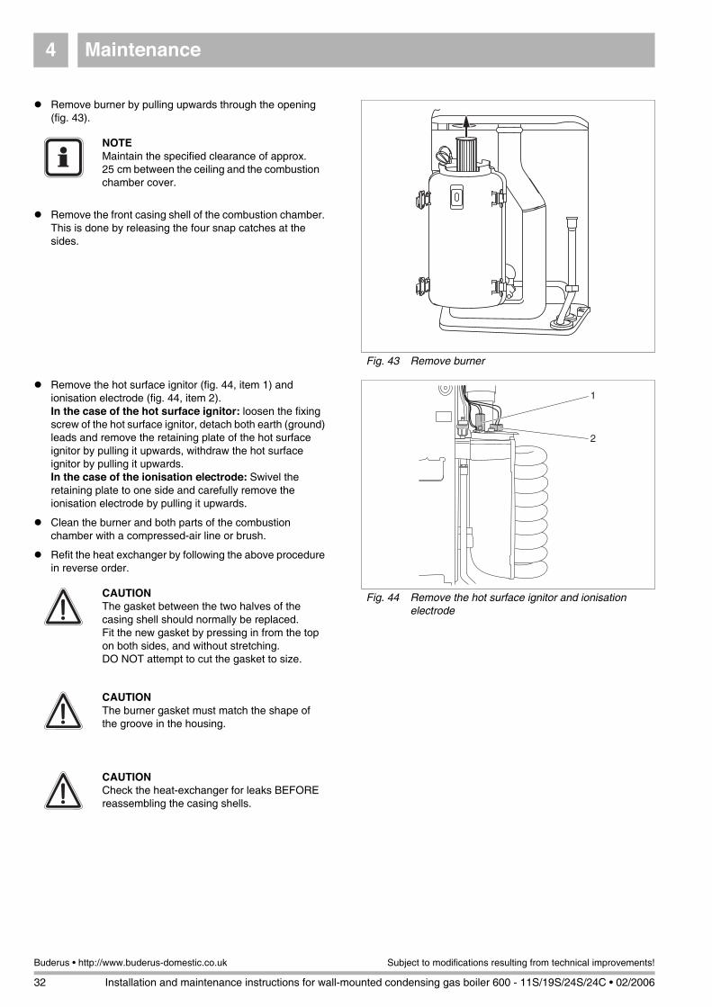
Remove burner by pulling upwards through the opening (fig. 43).
Remove the front casing shell of the combustion chamber. This is done by releasing the four snap catches at the sides.
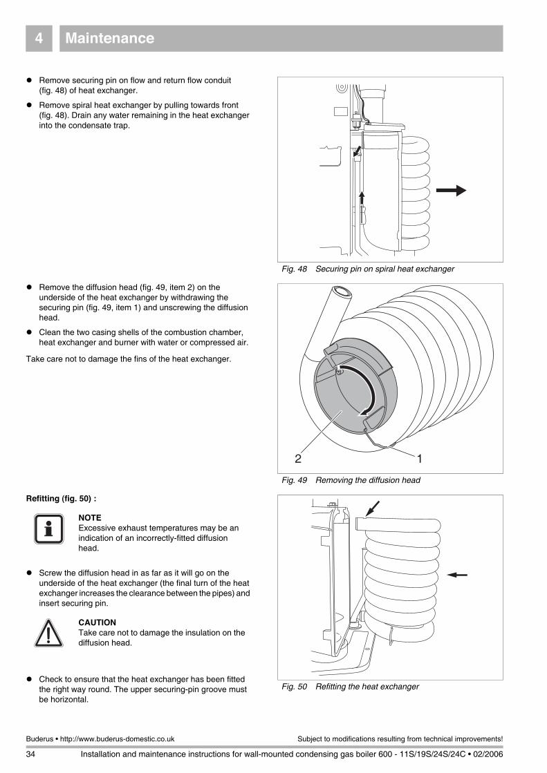
Remove the hot surface ignitor (fig. 44, item 1) and ionisation electrode (fig. 44, item 2).In the case of the hot surface ignitor: loosen the fixing screw of the hot surface ignitor, detach both earth (ground) leads and remove the retaining plate of the hot surface ignitor by pulling it upwards, withdraw the hot surface ignitor by pulling it upwards.In the case of the ionisation electrode: Swivel the retaining plate to one side and carefully remove the ionisation electrode by pulling it upwards.
Clean the burner and both parts of the combustion chamber with a compressed-air line or brush.
Refit the heat exchanger by following the above procedure in reverse order.
Fig. 43 Remove burner
NOTEMaintain the specified clearance of approx. 25 cm between the ceiling and the combustion chamber cover.
Fig. 44 Remove the hot surface ignitor and ionisation electrode
1
2
CAUTIONThe gasket between the two halves of the casing shell should normally be replaced. Fit the new gasket by pressing in from the top on both sides, and without stretching. DO NOT attempt to cut the gasket to size.
CAUTIONThe burner gasket must match the shape of the groove in the housing.
CAUTIONCheck the heat-exchanger for leaks BEFORE reassembling the casing shells.

Maintenance 4
Installation and maintenance instructions for wall-mounted condensing gas boiler 600 - 11S/19S/24S/24C • 02/2006 33
Subject to modifications resulting from technical improvements! Buderus • http://www.buderus-domestic.co.uk
4.1.2 Cleaning the heat exchanger after dismantling
Disconnect the system from the power supply.
Close the gas shutoff valve.
Loosen the retaining screw and remove the casing.
Close the heating shutoff valves and drain the system.
Open snap closures and remove combustion-chamber cover.
Release plug-in connection of fan power lead (fig. 40, item 1), burner-control unit fan control lead (fig. 40, item 2) and gas-burner assembly (fig. 40, item 3).
Loosen union nut on gas valve assembly (fig. 40, item 4).
Push safety plate out of way.
Turn air suction tube and pull off from below.
Swivel the air combination unit forward (fig. 41, item 1).
Pull the air combination unit up and out of bayonet connector (fig. 41, item 2) and remove via front of unit.
Remove burner gasket (fig. 42, item 1) and rubber seal in combustion chamber from top (fig. 42, item 2).
Remove burner by pulling upwards through the opening (fig. 47, item 1) and release the four retaining clips (fig. 47, item 2).
Remove the front casing shell of the combustion chamber.
Remove the hot surface ignitor (fig. 44, item 1) and ionisation electrode (fig. 44, item 2).In the case of the hot surface ignitor: Loosen the fixing screw of the hot surface ignitor, detach both earth (ground) leads and remove the retaining plate of the hot surface ignitor by pulling it upwards, withdraw the hot surface ignitor by pulling it upwards.In the case of the ionisation electrode: Swivel the retaining plate to one side and carefully remove the ionisation electrode by pulling it upwards.
Fig. 45 Draining the system
Drain
temporaryhose
Stopvalve
Stopvalve
DH
W C
old
(com
bi o
nly)
CH
Flo
w
CH
Ret
urn
CAUTIONCut hot water on supply side by closing the heating shutoff valve.
CAUTIONDrain the system via the temporary filling loop (fig. 45) or the screw-in drain plug (fig. 46, item 1) located under the pump.
Fig. 46 Screw-in drain plug
1
Fig. 47 Remove burner and release retaining clips
1
2
Maintenance4
34 Installation and maintenance instructions for wall-mounted condensing gas boiler 600 - 11S/19S/24S/24C • 02/2006
Buderus • http://www.buderus-domestic.co.uk Subject to modifications resulting from technical improvements!
Remove securing pin on flow and return flow conduit (fig. 48) of heat exchanger.
Remove spiral heat exchanger by pulling towards front (fig. 48). Drain any water remaining in the heat exchanger into the condensate trap.
Remove the diffusion head (fig. 49, item 2) on the underside of the heat exchanger by withdrawing the securing pin (fig. 49, item 1) and unscrewing the diffusion head.
Clean the two casing shells of the combustion chamber, heat exchanger and burner with water or compressed air.
Take care not to damage the fins of the heat exchanger.
Refitting (fig. 50) :
Screw the diffusion head in as far as it will go on the underside of the heat exchanger (the final turn of the heat exchanger increases the clearance between the pipes) and insert securing pin.
Check to ensure that the heat exchanger has been fitted the right way round. The upper securing-pin groove must be horizontal.
Fig. 48 Securing pin on spiral heat exchanger
Fig. 49 Removing the diffusion head
12
Fig. 50 Refitting the heat exchanger
NOTEExcessive exhaust temperatures may be an indication of an incorrectly-fitted diffusion head.
CAUTIONTake care not to damage the insulation on the diffusion head.

Maintenance 4
Installation and maintenance instructions for wall-mounted condensing gas boiler 600 - 11S/19S/24S/24C • 02/2006 35
Subject to modifications resulting from technical improvements! Buderus • http://www.buderus-domestic.co.uk
Refit the heat exchanger by following the above procedure in reverse. Note the following:
– The gasket between the two halves of the casing shell should normally be replaced. Fit the new gasket by pressing in from the top on both sides, and without stretching. DO NOT attempt to cut the gasket to size.
– Check the heat-exchanger for leaks BEFORE reassembling the casing shells.
Check O-ring seals (spiral), and replace as required.
Smear the O-ring seal with a thin layer of silicone grease.
4.1.3 Cleaning the condensate trap
Remove the trap from the sleeve with the lip seal facing downwards (fig. 51, item 1) and withdraw it from the outlet (fig. 51, item 2).
Remove the safety cover and clean the trap.
Fill the syphon with water and then reassemble in reverse order.
Measuring the gas input pressure (flow pressure).
Check the gas/air ratio.
Leak test in operational condition.
Measuring the carbon monoxide content.
Carry out function testing.
4.2 Flushing out the hot-water heat exchanger
Turn mains power switch to “0”.
Shut cold-water tap (accessory).
Open a hot-water tap (e.g. at the washbasin) and then close it again in order to check the pressure of the water being supplied.
Loosen the cable on the stand-by sensor.
Release the plastic clip from the bottom insulation of the hot-water heat exchanger and remove the insulation.
Connect the system to a power flusher unit and flush it out.
Remove temperature sensor for DWH warm out and stand-by sensor, and replace with flushing hoses (fig. 52).
Reassemble.
Open cold-water tap (accessory).
Open hot-water tap (e.g. at washbasin) and thoroughly flush out system.
Turn mains power switch to “I”.
Fig. 51 Removing the condensate trap
2
1
Fig. 52 Flushing out the hot-water heat exchanger
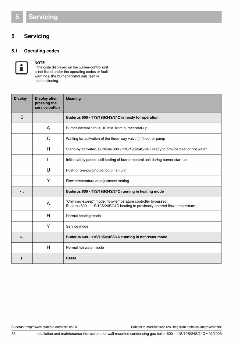
Servicing5
36 Installation and maintenance instructions for wall-mounted condensing gas boiler 600 - 11S/19S/24S/24C • 02/2006
Buderus • http://www.buderus-domestic.co.uk Subject to modifications resulting from technical improvements!
5 Servicing
5.1 Operating codes
NOTEIf the code displayed on the burner-control unit is not listed under the operating codes or fault warnings, the burner-control unit itself is malfunctioning.
Display Display after pressing the service button
Meaning
0 Buderus 600 - 11S/19S/24S/24C is ready for operation
A Burner interval circuit, 10 min. from burner start-up
C Waiting for activation of the three-way valve (if fitted) or pump
H Stand-by activated, Buderus 600 - 11S/19S/24S/24C ready to provide heat or hot water
L Initial safety period: self-testing of burner-control unit during burner start-up
U Post- or pre-purging period of fan unit
Y Flow temperature at adjustment setting
-. Buderus 600 - 11S/19S/24S/24C running in heating mode
A “Chimney-sweep” mode, flow-temperature controller bypassed,Buderus 600 - 11S/19S/24S/24C heating to previously-entered flow temperature.
H Normal heating mode
Y Service mode
=. Buderus 600 - 11S/19S/24S/24C running in hot-water mode
H Normal hot water mode
r Reset

Servicing 5
Installation and maintenance instructions for wall-mounted condensing gas boiler 600 - 11S/19S/24S/24C • 02/2006 37
Subject to modifications resulting from technical improvements! Buderus • http://www.buderus-domestic.co.uk
5.2 Fault codes
Code Meaning
2C Safety sensor exceeds 100 °C
Possible cause
Action
1 Resistance in the installation is too high Check if not all (thermostatic) radiator valves are clogged with dirt.
2 Heating capacity is too large for the installation Adjust the heating capacity (see subsection 2.1.10)
3 Safety sensor is faulty Measure if resistance over the sensor is correct. If not replace safety sensor (see subsection 5.3.11, subsection 5.3.12, subsection 5.3.13)
4 Problem with the pump or pump cabling (no circulation)
Check if the pump cabling is faulty or if the pump is stuck(see subsection 5.3.9)
5 Water pressure is too low in the installation Top up the system (see subsection 2.1.1)
Code Meaning
2F Temperature difference between the safety sensor and flow sensor is greater than or equal to 15 °K
Possible cause
Action
1 Resistance in the installation is too high Check if not all (thermostatic) radiator valves are closed or clogged with dirt
2 Safety sensor is dirty or faulty Check the safety sensor for dirt. Measure if resistance over the sensor is correct. If not replace safety sensor (see subsection 5.3.11, subsection 5.3.12, subsection 5.3.13)
3 Flow sensor is dirty or faulty Check the sensor, replace if necessary (see subsection 5.3.14, subsection 5.3.15, subsection 5.3.16)
4 Problem with the pump or pump cabling (no circulation)
Check if the pump cabling is faulty or if the pump is stuck. Replace pump if necessary (see subsection 5.3.9 and subsection 5.3.10)
5 Water pressure is too low in the installation Top up the system (see subsection 2.1.1)
Code Meaning
2P Safety sensor rises faster than 5 °C/sec.
Possible cause
Action
1 Heating capacity is too large for the installation Adjust the heating capacity (see subsection 2.1.10)
2 Resistance in the installation is too high Check if not all (thermostatic) radiator valves are closed or clogged with dirt
3 Safety sensor is dirty or faulty Check the safety sensor for dirt. Measure if resistance over the sensor is correct. If not replace safety sensor (see subsection 5.3.11, subsection 5.3.12, subsection 5.3.13)
4 External domestic hot water tank is too small for the heating capacity
Top up the system (see subsection 2.1.1)

Servicing5
38 Installation and maintenance instructions for wall-mounted condensing gas boiler 600 - 11S/19S/24S/24C • 02/2006
Buderus • http://www.buderus-domestic.co.uk Subject to modifications resulting from technical improvements!
Code Meaning
3C Bad plug-in connection at cable harness, or damaged wiring
Possible cause
Action
1 Cable harness is faulty Check cable harness for faults and bad connections
2 Connectors at the back of the UBA are loose or faulty Check the connectors at the back of the UBA
3 UBA might be faulty Check the UBA by temporarily connecting an other UBA (see subsection 5.3.3)
Code Meaning
4A Flow sensor exceeds 100 °C
Possible cause
Action
1 Flow sensor is dirty or faulty Check the sensor, replace if necessary (see subsection 5.3.14, subsection 5.3.15, subsection 5.3.16)
2 There is a problem with the pump or pump cabling (no circulation)
Check if the pump cabling is faulty or if the pump is stuck. Replace pump if necessary (see subsection 5.3.9 and subsection 5.3.10)
3 Water pressure is too low in the installation Top up the system (see subsection 2.1.1)
Code Meaning
4C F2 fuse malfunction, or flue gas thermostat active
Possible cause
Action
1 Water pressure is too low in the installation Top up the system (see subsection 2.1.1)
2 Heat exchanger is dirty Check for a dirty heat exchanger and clean if necessary. (see subsection 4.1)
3 Flue gas retarder faulty or missing Check if the flue gas retarder is installed in the heat exchanger
4 Heat exchanger has a problem Purge heat exchanger
Code Meaning
4F Flow sensor exceeds 100 °C
Possible cause
Action
1 Resistance in the installation is too high Check if not all (thermostatic) radiator valves are clogged with dirt
2 Heating capacity is too large for the installation Adjust the heating capacity
3 Safety sensor is faulty Check the sensor and measure if resistance over the sensor is correct. If not replace safety sensor (see subsection 5.3.11, subsection 5.3.12, subsection 5.3.13)
4 Problem with the pump or pump cabling (no circulation) Check if the pump cabling is faulty or if the pump is stuck(see subsection 5.3.9)
5 Water pressure is too low in the installation Top up the system (see subsection 2.1.1)
Code Meaning
4H System error
Possible cause
Action
1 Boiler is in operation for DHW due to a dripping faucet Check for dripping faucets

Servicing 5
Installation and maintenance instructions for wall-mounted condensing gas boiler 600 - 11S/19S/24S/24C • 02/2006 39
Subject to modifications resulting from technical improvements! Buderus • http://www.buderus-domestic.co.uk
Code Meaning
4L Short circuit in safety sensor
Possible cause
Action
1 Safety sensor is faulty Check the sensor and measure if resistance over the sensor is correct. If not replace safety sensor (see subsection 5.3.11, subsection 5.3.12, subsection 5.3.13)
2 A short or bad connection in the cable harness Check the cable harness and/or connector of the sensor
3 UBA might be faulty Check the UBA by temporarily connecting a different UBA(see subsection 5.3.3)
Code Meaning
4P Safety sensor has a loose connection or is defective
Possible cause
Action
1 Safety sensor faulty or disconnected Check the sensor and measure if resistance over the sensor is correct. If not replace safety sensor (see subsection 5.3.11, subsection 5.3.12, subsection 5.3.13)
2 A short or bad connection in the cable harness Check the cable harness and/or connector of the sensor
3 UBA might be faulty Check the UBA by temporarily connecting a different UBA (see subsection 5.3.3)
Code Meaning
4U Short circuit in flow sensor
Possible cause
Action
1 Flow sensor is dirty or faulty Check the sensor, replace if necessary (see subsection 5.3.14, subsection 5.3.15, subsection 5.3.16)
2 A short or bad connection in the cable harness Check the cable harness and/or connector of the sensor
3 UBA might be faulty Check the UBA by temporarily connecting a different UBA (see subsection 5.3.3)
Code Meaning
4Y Flow sensor interrupted
Possible cause
Action
1 Flow sensor faulty or disconnected Check the sensor and measure if resistance over the sensor is correct. If not replace safety sensor (see subsection 5.3.14, subsection 5.3.15, subsection 5.3.16)
2 A short or bad connection in the cable harness Check the cable harness and/or connector of the sensor
3 UBA might be faulty Check the UBA by temporarily connecting a different UBA (see subsection 5.3.3)
Servicing5
40 Installation and maintenance instructions for wall-mounted condensing gas boiler 600 - 11S/19S/24S/24C • 02/2006
Buderus • http://www.buderus-domestic.co.uk Subject to modifications resulting from technical improvements!
Code Meaning
5C Boiler shut down after connection with Service Tool
Possible cause
Action
1 Service tool connection Press reset. If fault code remains than try to temporarily connect a different UBA (see subsection 5.3.3)
2 A short or bad connection in the cable harness Check the cable harness and/or connector of the sensor
3 UBA might be faulty Check the UBA by temporarily connecting an other UBA (see subsection 5.3.3)
Code Meaning
6A F1 fuse defective, or no ionisation message after ignition
Possible cause
Action
1 There is no flame, ionisation electrode doesn’t glow, fan is turning
– Check wiring of the hot surface ignitor, measure the resistance of the hot surface ignitor (should be between 50 and 300 Ohm). Replace hot surface ignitor if necessary (see subsection 5.3.19 and subsection 5.3.20)
– Check the UBA’s F1 fuse, replace if necessary
2 There is no flame, ionisation electrode does glow, fan isn’t turning
– Check the fan and KIM connectors and the UBA fuses
3 There is no flame, ionisation electrode and fan are working
– Check and adjust the gas/air ratio (see subsection 2.1.12)
– Check for 24 V~ on the gas valve during start up
– Check the gas-supply pressure (see subsection 2.1.11), this should be higher than 20 mbar for natural gas.
– Check the earthing cable connections (yellow/green wire).
– Check the cabling on the ionisation electrode
4 There is a flame, but the flame disappears when the fan starts up
– Check the gas-supply pressure (see subsection 2.1.11), this should be higher than 20 mbar for natural gas.
– Check and adjust the gas/air ratio (see subsection 2.1.12)
– Check the earthing cable connections (yellow/green wire)
– Check the cabling on the ionisation electrode
– Press reset. If fault code remains than try to temporarily connect a different UBA (see subsection 5.3.3)

Servicing 5
Installation and maintenance instructions for wall-mounted condensing gas boiler 600 - 11S/19S/24S/24C • 02/2006 41
Subject to modifications resulting from technical improvements! Buderus • http://www.buderus-domestic.co.uk
Code Meaning
6C Ionisation message, but no flame
Possible cause
Action
1 There is no flame, ionisation electrode doesn’t glow, fan is turning
– Check wiring of the hot surface ignitor, measure the resistance of the hot surface ignitor (should be between 50 and 300 Ohm). Replace hot surface ignitor if necessary (see subsection 5.3.19 and subsection 5.3.20)
– Check the UBA’s F1 fuse, replace if necessary
2 There is no flame, ionisation electrode does glow, fan isn’t turning
– Check the fan and KIM connectors and the UBA fuses
3 There is no flame, ionisation electrode and fan are working
– Check and adjust the gas/air ratio (see subsection 2.1.12)
– Check for 24V – on the gas valve during start up
– Check the gas-supply pressure (see subsection 2.1.11), this should be higher than 20 mbar for natural gas.
– Check the earthing cable connections (yellow/green wire).
– Check the cabling on the ionisation electrode
4 There is a flame, but the flame disappears when the fan starts up
– The gas valve doesn’t close properly. If there is still more than 20 V~ on the gas valve when there is no heat demand then check the UBA by temporarily connecting a different UBA.
– Check ionisation electrode/circuit (see subsection 2.1.15 and subsection 5.3.22)
– When both the UBA and the ionisation electrode/circuit are OK, then replace the gas valve
– Press reset. If fault code remains than try to temporarily connect a different UBA (see subsection 5.3.3)
Code Meaning
6H Flame dies out after gas valve is opened
Possible cause
Action
1 Gas/air ratio not in order Check and adjust the gas/air ratio (see subsection 2.1.12)
2 Gas supply pressure may need adjusting Check the gas-supply pressure (see subsection 2.1.11), this should be higher than 20 mbar for natural gas
3 Earthing cable may be faulty Check the earthing cable connections (yellow/green wire)
4 Ionisation electrode may be faulty Check the cabling on the ionisation electrode
Code Meaning
6L Flame goes out during warm-up phase
Possible cause
Action
1 Gas/air ratio not in order Check and adjust the gas/air ratio (see subsection 2.1.12)
2Gas supply pressure may need adjusting
Check the gas-supply pressure (see subsection 2.1.11), this should be higher than 20 mbar for natural gas
3 Earthing cable may be faulty Check the earthing cable connections (yellow/green wire)
4 Ionisation electrode may be faulty Check the cabling on the ionisation electrode

Servicing5
42 Installation and maintenance instructions for wall-mounted condensing gas boiler 600 - 11S/19S/24S/24C • 02/2006
Buderus • http://www.buderus-domestic.co.uk Subject to modifications resulting from technical improvements!
Code Meaning
7A Voltage in burner-control unit too low (lower than 187 V~) or too high (higher than 246 V~)
Possible cause
Action
1 Regulating device may have to cope with interference – Check if for example induction fields interfere with the regulating device
– Check if the are any peaks in the electrical network caused by maybe windmills or a power generator
Code Meaning
7C Mains supply interrupted
Possible cause
Action
1 A problem with the mains supply Carry out a power test procedure for safe testing of the mains electrical supply
2 Reset button pressed too briefly Press the Reset button until "r" appears in the display
Code Meaning
7F F3 fuse defect, or burner control unit error
Possible cause
Action
1 Short circuit in the 24V circuit (three-way-valve or connector)
Check for a short circuit and replace the F3 fuse
2 Regulating device may have to cope with interference – Check if for example induction fields interfere with the regulating device
– Check if the are any peaks in the electrical network caused by maybe windmills or a power generator
Code Meaning
7H Voltage peaks in the UBA
Possible cause
Action
1 Regulating device may have to cope with interference – Check if for example induction fields interfere with the regulating device
– Check if the are any peaks in the electrical network caused by maybe windmills or a power generator
Code Meaning
7L Internal UBA error
Possible cause
Action
1 Regulating device may have to cope with interference – Check if for example induction fields interfere with the regulating device
– Check if the are any peaks in the electrical network caused by maybe windmills or a power generator

Servicing 5
Installation and maintenance instructions for wall-mounted condensing gas boiler 600 - 11S/19S/24S/24C • 02/2006 43
Subject to modifications resulting from technical improvements! Buderus • http://www.buderus-domestic.co.uk
Code Meaning
8Y Gas fault
Possible cause
Action
1 External switching contact (e.g. temperature-monitoring device for underfloor heating has been tripped or gas pressure too low
Check gas pressure detector is defective or the wires have not been properly connected to the back of the UBA (see subsection 5.3.6)
Code Meaning
9A System error
Possible cause
Action
1 Regulating device may have to cope with interference – Check if for example induction fields interfere with the regulating device
– Check if the are any peaks in the electrical network caused by maybe windmills or a power generator
– Check for dripping hot water taps on the combination boiler only
2 UBA may be defective Press reset. If fault code remains then try to temporarily connect a different UBA
Code Meaning
9C KIM error
Possible cause
Action
1 KIM connected incorrectly or KIM defective Check the KIM connector and fan connector. If the connectors are fine then contact Buderus
Code Meaning
9F/H System error
Possible cause
Action
1 Regulating device may have to cope with interference – Check if for example induction fields interfere with the regulating device
– Check if the are any peaks in the electrical network caused by maybe windmills or a power generator
2 UBA may be defective Press reset. If fault code remains then try to temporarily connect a different UBA (see subsection 5.3.3)
Code Meaning
9L Gas valve assembly error
Possible cause
Action
1 Wiring to the gas valve incorrect, or loose wiring connections in UBA
– Check the electrical connections of the gas valve.
– Measure the resistance of the gas valve (18-55 Ohm)
– Check if for example induction fields interfere with the regulating device
2 UBA may be defective – Press reset. If fault code remains then try to temporarily connect a different UBA (see subsection 5.3.3)
3 Peaks in the electrical network – Check if the are any peaks in the electrical network caused by maybe windmills or a power generator
Servicing5
44 Installation and maintenance instructions for wall-mounted condensing gas boiler 600 - 11S/19S/24S/24C • 02/2006
Buderus • http://www.buderus-domestic.co.uk Subject to modifications resulting from technical improvements!
Code Meaning
9U KIM defective
Possible cause
Action
1 KIM connected incorrectly or KIM defective Check the KIM connector and fan connector.If the connectors are fine then contact Buderus
Code Meaning
E with any character but P
UBA defective
Possible cause
Action
1 Regulating device may have to cope with interference – Check if for example induction fields interfere with the regulating device
– Check if the are any peaks in the electrical network caused by maybe windmills or a power generator
2 UBA may be defective – Press reset. If fault code remains then try to temporarily connect a different UBA (see subsection 5.3.3)
Code Meaning
EP Non compatible UBA fitted
Possible cause
Action
1 Regulating device may have to cope with interference – Check if for example induction fields interfere with the regulating device
– Check if the are any peaks in the electrical network caused by maybe windmills or a power generator
2 KIM connected incorrectly or KIM defective – Check the KIM connector and fan connector. If the connectors are fine then contact Buderus
Problem: No DHW, despite the system being operational
– Set chimney sweep switch to "0"
– Check three-way valve replace if necessary
– Check DHW sensor and replace if necessary
Problem: No heating, despite that there is a demand for heat and the boiler is operational
– Check regulating device configuration and/ or the wiring
– Check the wiring between the regulating device and the UBA (see subsection 5.3.6)
– Check all the wiring
– Check the UBA and replace if necessary (see subsection 5.3.3)

Servicing 5
Installation and maintenance instructions for wall-mounted condensing gas boiler 600 - 11S/19S/24S/24C • 02/2006 45
Subject to modifications resulting from technical improvements! Buderus • http://www.buderus-domestic.co.uk
5.3 Checking and replacing parts
5.3.1 Checking the flue gas sensor
Detach plug-and-socket connection on cable to flue gas sensor. Ensure that no cable is earthed (grounded) at any point.
Allow the flue gas sensor to cool down.Activation temperature:600 - 11S / 19S / 24S / 24C: 105 °C
Check flue gas sensor for free throughput. If throughput is not free, the flue gas sensor is defective.
Replace any flue gas sensor found to be defective. Ensure you use only genuine Buderus spare parts.
If the flue gas sensor is working correctly, plug it in once more.
5.3.2 Replacing the flue gas sensor
Unscrew the flow-backup mounting.
Detach the cable plug at the flue gas sensor.
Loosen both retaining screws on the flue gas sensor.
Remove the flue gas sensor and replace with a new unit (fig. 53).
Retighten the retaining screws.
Reconnect the cable plug.
Screw the mounting into place.
5.3.3 Replacing the UBA
Disconnect the system from the power supply.
Loosen crosshead screw (fig. 54, item 1) on UBA housing.
Swivel UBA housing downwards.
Fig. 53 600 - 11S / 19S / 24S / 24C: replacing the flue gas sensor
Fig. 54 Swivel UBA housing downwards
1
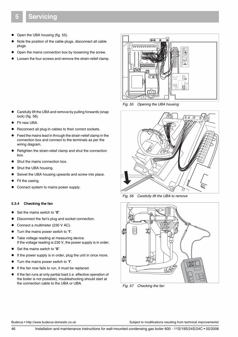
Servicing5
46 Installation and maintenance instructions for wall-mounted condensing gas boiler 600 - 11S/19S/24S/24C • 02/2006
Buderus • http://www.buderus-domestic.co.uk Subject to modifications resulting from technical improvements!
Open the UBA housing (fig. 55).
Note the position of the cable plugs, disconnect all cable plugs.
Open the mains connection box by loosening the screw.
Loosen the four screws and remove the strain-relief clamp.
Carefully lift the UBA and remove by pulling forwards (snap lock) (fig. 56).
Fit new UBA.
Reconnect all plug-in cables to their correct sockets.
Feed the mains lead in through the strain-relief clamp in the connection box and connect to the terminals as per the wiring diagram.
Retighten the strain-relief clamp and shut the connection box.
Shut the mains connection box.
Shut the UBA housing.
Swivel the UBA housing upwards and screw into place.
Fit the casing.
Connect system to mains power supply.
5.3.4 Checking the fan
Set the mains switch to “0”.
Disconnect the fan's plug and socket connection.
Connect a multimeter (230 V AC).
Turn the mains power switch to “I”.
Take voltage reading at measuring device.If the voltage reading is 230 V, the power supply is in order.
Set the mains switch to “0”.
If the power supply is in order, plug the unit in once more.
Turn the mains power switch to “I”.
If the fan now fails to run, it must be replaced.
If the fan runs at only partial load (i.e. effective operation of the boiler is not possible), troubleshooting should start at the connection cable to the UBA or UBA.
Fig. 55 Opening the UBA housing
Fig. 56 Carefully lift the UBA to remove
Fig. 57 Checking the fan
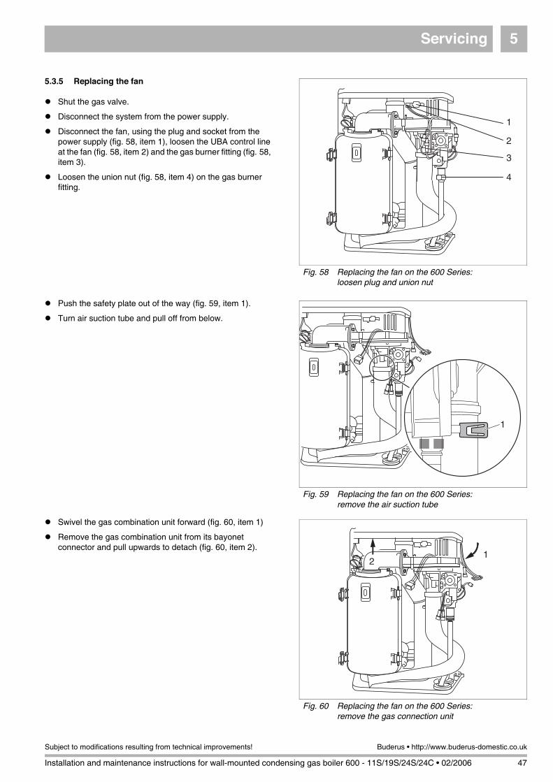
Servicing 5
Installation and maintenance instructions for wall-mounted condensing gas boiler 600 - 11S/19S/24S/24C • 02/2006 47
Subject to modifications resulting from technical improvements! Buderus • http://www.buderus-domestic.co.uk
5.3.5 Replacing the fan
Shut the gas valve.
Disconnect the system from the power supply.
Disconnect the fan, using the plug and socket from the power supply (fig. 58, item 1), loosen the UBA control line at the fan (fig. 58, item 2) and the gas burner fitting (fig. 58, item 3).
Loosen the union nut (fig. 58, item 4) on the gas burner fitting.
Push the safety plate out of the way (fig. 59, item 1).
Turn air suction tube and pull off from below.
Swivel the gas combination unit forward (fig. 60, item 1)
Remove the gas combination unit from its bayonet connector and pull upwards to detach (fig. 60, item 2).
Fig. 58 Replacing the fan on the 600 Series:loosen plug and union nut
1
2
3
4
Fig. 59 Replacing the fan on the 600 Series:remove the air suction tube
1
Fig. 60 Replacing the fan on the 600 Series:remove the gas connection unit
12
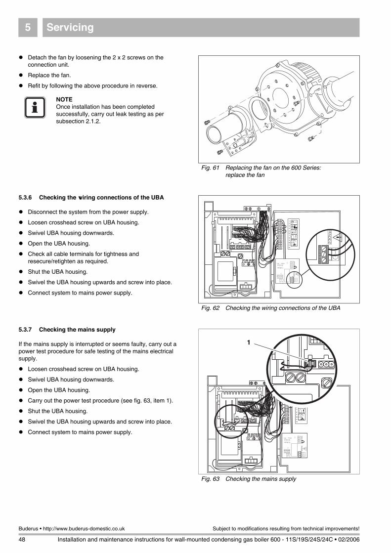
Servicing5
48 Installation and maintenance instructions for wall-mounted condensing gas boiler 600 - 11S/19S/24S/24C • 02/2006
Buderus • http://www.buderus-domestic.co.uk Subject to modifications resulting from technical improvements!
Detach the fan by loosening the 2 x 2 screws on the connection unit.
Replace the fan.
Refit by following the above procedure in reverse.
5.3.6 Checking the wiring connections of the UBA
Disconnect the system from the power supply.
Loosen crosshead screw on UBA housing.
Swivel UBA housing downwards.
Open the UBA housing.
Check all cable terminals for tightness and resecure/retighten as required.
Shut the UBA housing.
Swivel the UBA housing upwards and screw into place.
Connect system to mains power supply.
5.3.7 Checking the mains supply
If the mains supply is interrupted or seems faulty, carry out a power test procedure for safe testing of the mains electrical supply.
Loosen crosshead screw on UBA housing.
Swivel UBA housing downwards.
Open the UBA housing.
Carry out the power test procedure (see fig. 63, item 1).
Shut the UBA housing.
Swivel the UBA housing upwards and screw into place.
Connect system to mains power supply.
Fig. 61 Replacing the fan on the 600 Series:replace the fan
NOTEOnce installation has been completed successfully, carry out leak testing as per subsection 2.1.2.
Fig. 62 Checking the wiring connections of the UBA
Fig. 63 Checking the mains supply
1

Servicing 5
Installation and maintenance instructions for wall-mounted condensing gas boiler 600 - 11S/19S/24S/24C • 02/2006 49
Subject to modifications resulting from technical improvements! Buderus • http://www.buderus-domestic.co.uk
5.3.8 Checking the miniature fuses
Disconnect the system from the power supply.
Loosen crosshead screw on UBA housing.
Swivel UBA housing downwards.
Open the UBA housing.
Check miniature fuses (fig. 64) for correct functioning, or carry out visual inspection. If defective, fit new fuse.All fuses a rated 230 Vac - 1.25 AT.
Shut the UBA housing.
Swivel the UBA housing upwards and screw into place.
Connect system to mains power supply.
5.3.9 Checking the pump
Remove screw plug on the pump (fig. 65).
Turn the UBA mains power switch to “I”.
Check to ensure that the pump is running. The pump’s running mechanism may become blocked if the heating system has been out of use for an extended period. Use a screwdriver to rotate the pump in its normal running direction and release the blockage in question. If this procedure does not work, replace the pump.
If the pump is working correctly, screw the plug back in.
5.3.10 Replacing the pump
Disconnect the system from the power supply.
Shut the servicing valve.
Drain the 600 - 11S / 19S / 24S / 24C as per the "Installation and Servicing Instructions".
Loosen the screw on the terminal box (fig. 66, item 2) of the pump and open the terminal box. Note the wiring layout, and loosen the cables (fig. 66, item 1).
Loosen the screw-in connections on the pump (fig. 66, item 3) and remove the pump.
Fit new pump and connect to system.
Connect cables in previously-noted order inside terminal box, close terminal box and screw shut.
Connect system to mains power supply.
Open servicing valves.
Fig. 64 Checking the miniature fuse
1
2
3
Fuse Function
1 Hot surface ignitor
2 UBA, sensors, thermostat valve
3 UBA, three-way valve
Fig. 65 600 - 11S / 19S / 24S / 24C: checking the pump
Fig. 66 600 - 11S / 19S / 24S / 24C: replacing the pump
3
2
1
NOTEFill the 600 - 11S / 19S / 24S / 24C and purge the system of air.
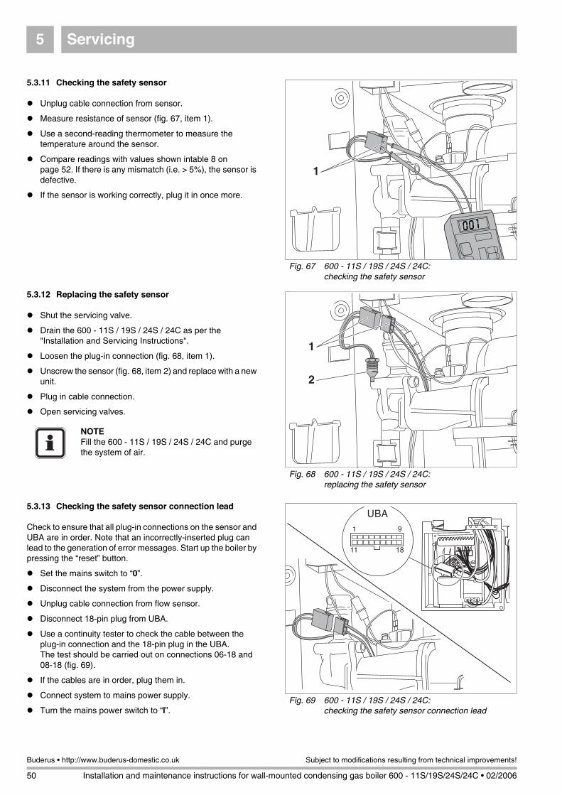
Servicing5
50 Installation and maintenance instructions for wall-mounted condensing gas boiler 600 - 11S/19S/24S/24C • 02/2006
Buderus • http://www.buderus-domestic.co.uk Subject to modifications resulting from technical improvements!
5.3.11 Checking the safety sensor
Unplug cable connection from sensor.
Measure resistance of sensor (fig. 67, item 1).
Use a second-reading thermometer to measure the temperature around the sensor.
Compare readings with values shown intable 8 on page 52. If there is any mismatch (i.e. > 5%), the sensor is defective.
If the sensor is working correctly, plug it in once more.
5.3.12 Replacing the safety sensor
Shut the servicing valve.
Drain the 600 - 11S / 19S / 24S / 24C as per the "Installation and Servicing Instructions".
Loosen the plug-in connection (fig. 68, item 1).
Unscrew the sensor (fig. 68, item 2) and replace with a new unit.
Plug in cable connection.
Open servicing valves.
5.3.13 Checking the safety sensor connection lead
Check to ensure that all plug-in connections on the sensor and UBA are in order. Note that an incorrectly-inserted plug can lead to the generation of error messages. Start up the boiler by pressing the “reset” button.
Set the mains switch to “0”.
Disconnect the system from the power supply.
Unplug cable connection from flow sensor.
Disconnect 18-pin plug from UBA.
Use a continuity tester to check the cable between the plug-in connection and the 18-pin plug in the UBA.The test should be carried out on connections 06-18 and 08-18 (fig. 69).
If the cables are in order, plug them in.
Connect system to mains power supply.
Turn the mains power switch to “I”.
Fig. 67 600 - 11S / 19S / 24S / 24C: checking the safety sensor
Fig. 68 600 - 11S / 19S / 24S / 24C: replacing the safety sensor
NOTEFill the 600 - 11S / 19S / 24S / 24C and purge the system of air.
Fig. 69 600 - 11S / 19S / 24S / 24C: checking the safety sensor connection lead
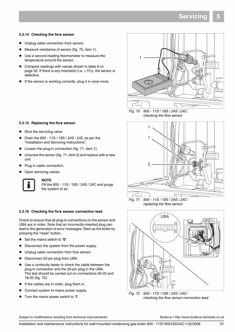
Servicing 5
Installation and maintenance instructions for wall-mounted condensing gas boiler 600 - 11S/19S/24S/24C • 02/2006 51
Subject to modifications resulting from technical improvements! Buderus • http://www.buderus-domestic.co.uk
5.3.14 Checking the flow sensor
Unplug cable connection from sensor.
Measure resistance of sensor (fig. 70, item 1).
Use a second-reading thermometer to measure the temperature around the sensor.
Compare readings with values shown in table 8 on page 52. If there is any mismatch (i.e. > 5%), the sensor is defective.
If the sensor is working correctly, plug it in once more.
5.3.15 Replacing the flow sensor
Shut the servicing valve.
Drain the 600 - 11S / 19S / 24S / 24C as per the "Installation and Servicing Instructions".
Loosen the plug-in connection (fig. 71, item 1).
Unscrew the sensor (fig. 71, item 2) and replace with a new unit.
Plug in cable connection.
Open servicing valves.
5.3.16 Checking the flow sensor connection lead
Check to ensure that all plug-in connections on the sensor and UBA are in order. Note that an incorrectly-inserted plug can lead to the generation of error messages. Start up the boiler by pressing the “reset” button.
Set the mains switch to “0”.
Disconnect the system from the power supply.
Unplug cable connection from flow sensor.
Disconnect 20-pin plug from UBA.
Use a continuity tester to check the cable between the plug-in connection and the 20-pin plug in the UBA.The test should be carried out on connections 05-20 and 18-20 (fig. 72).
If the cables are in order, plug them in.
Connect system to mains power supply.
Turn the mains power switch to “I”.
Fig. 70 600 - 11S / 19S / 24S / 24C: checking the flow sensor
1
Fig. 71 600 - 11S / 19S / 24S / 24C: replacing the flow sensor
1
1
2
NOTEFill the 600 - 11S / 19S / 24S / 24C and purge the system of air.
Fig. 72 600 - 11S / 19S / 24S / 24C: checking the flow sensor connection lead
� ��
����
���

Servicing5
52 Installation and maintenance instructions for wall-mounted condensing gas boiler 600 - 11S/19S/24S/24C • 02/2006
Buderus • http://www.buderus-domestic.co.uk Subject to modifications resulting from technical improvements!
5.3.17 Checking the hot water / boiler sensor
Disconnect the plug-and-socket connection on the hot water sensor cable (fig. 73, item 1) and/or the boilersensor (fig. 73, item 2).
Measure resistance, take a temperature reading at the thermal pressure gauge (tolerance ± 5 K) and compare with the values listed in table 8. If there is any marked mismatch, the hot-water sensor is defective.
If the hot water / boiler sensor is in order, plug it back in.
Table 8 Resistance values for hot water / boiler sensor(approximate values)
Fig. 73 Checking the hot water / boiler sensor
Fig. 74 Boiler temperature sensor diagram
2
1
Temperature [°C] Resistance [Ω]
0 29,490.0
5 23,462.0
10 18,787.0
15 15,136.0
20 12,268.0
25 10,000.0
30 8,197.0
35 6,754.0
40 5,594.0
45 4,656.0
50 3,893.0
55 3,271.0
60 2,760.0
65 2,339.0
70 1,990.0
75 1,700.0
80 1,458.0
85 1,255.0
90 1,084.0
95 1,939.6
100 1,817.2
Fig. 75 Outside temperature sensor diagram
(°C)
R (Ω)
0
5
10
15
20
25
-20
-15
-10
-5
50,00020,000 80,00040,00030,00010,000 60,000 70,000
Outside temperature sensor

Servicing 5
Installation and maintenance instructions for wall-mounted condensing gas boiler 600 - 11S/19S/24S/24C • 02/2006 53
Subject to modifications resulting from technical improvements! Buderus • http://www.buderus-domestic.co.uk
5.3.18 Changing the hot water / boiler sensor
Shut the servicing valve.
Drain the 600 - 11S / 19S / 24S / 24C as per the "Installation and Servicing Instructions".
Disconnection plug-and-socket connection on cable to hot water / boiler sensor.
Remove insulation mounting (fig. 76, item 1) and detach insulation.
Pull out the sensor fuses (fig. 77).
Unscrew hot water / boiler sensor and replace with new unit.
Refit insulation and corresponding mounting elements.
Plug cable connection in once more.
Open servicing valves.
Fill the 600 - 11S / 19S / 24S / 24C and purge the system of air as indicated in the installation and servicing instructions.
5.3.19 Checking the hot surface ignitor
Disconnect the system from the power supply.
Loosen crosshead screw on UBA housing.
Swivel UBA housing downwards.
Open the UBA housing.
Unplug and remove hot surface ignitor from UBA housing (fig. 78).
Check hot surface ignitor for free throughput. If throughput is free, the hot surface ignitor is in order.
If the hot surface ignitor is in order, plug the cable into the UBA housing.
Shut the UBA housing.
Swivel the UBA housing upwards and screw into place.
Connect system to mains power supply.
Fig. 76 Changing the hot water / boiler sensor
1
Fig. 77 Changing the hot water / boiler sensor
1
2
Fig. 78 Checking the hot surface ignitor
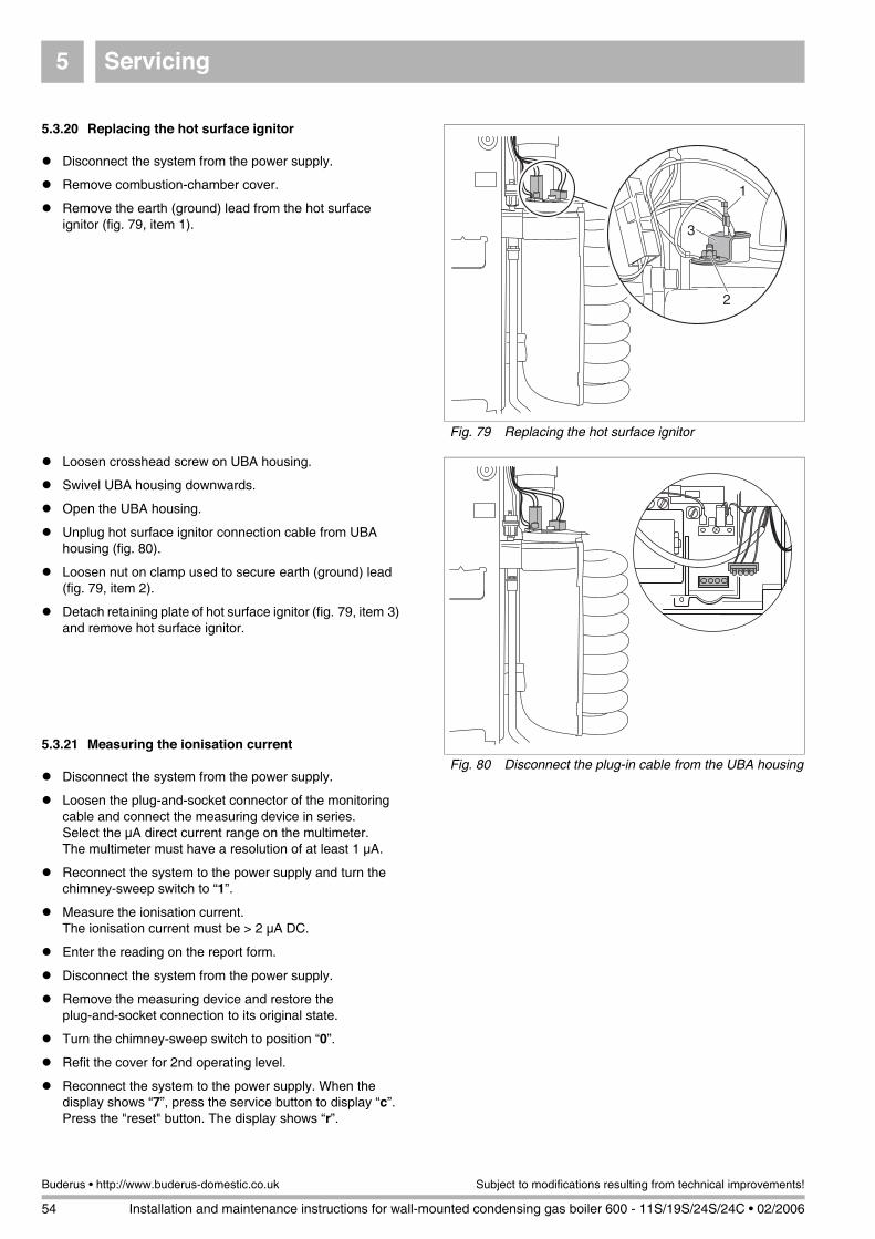
Servicing5
54 Installation and maintenance instructions for wall-mounted condensing gas boiler 600 - 11S/19S/24S/24C • 02/2006
Buderus • http://www.buderus-domestic.co.uk Subject to modifications resulting from technical improvements!
5.3.20 Replacing the hot surface ignitor
Disconnect the system from the power supply.
Remove combustion-chamber cover.
Remove the earth (ground) lead from the hot surface ignitor (fig. 79, item 1).
Loosen crosshead screw on UBA housing.
Swivel UBA housing downwards.
Open the UBA housing.
Unplug hot surface ignitor connection cable from UBA housing (fig. 80).
Loosen nut on clamp used to secure earth (ground) lead (fig. 79, item 2).
Detach retaining plate of hot surface ignitor (fig. 79, item 3) and remove hot surface ignitor.
5.3.21 Measuring the ionisation current
Disconnect the system from the power supply.
Loosen the plug-and-socket connector of the monitoring cable and connect the measuring device in series. Select the µA direct current range on the multimeter. The multimeter must have a resolution of at least 1 µA.
Reconnect the system to the power supply and turn the chimney-sweep switch to “1”.
Measure the ionisation current.The ionisation current must be > 2 µA DC.
Enter the reading on the report form.
Disconnect the system from the power supply.
Remove the measuring device and restore the plug-and-socket connection to its original state.
Turn the chimney-sweep switch to position “0”.
Refit the cover for 2nd operating level.
Reconnect the system to the power supply. When the display shows “7”, press the service button to display “c”. Press the "reset" button. The display shows “r”.
Fig. 79 Replacing the hot surface ignitor
1
2
3
Fig. 80 Disconnect the plug-in cable from the UBA housing
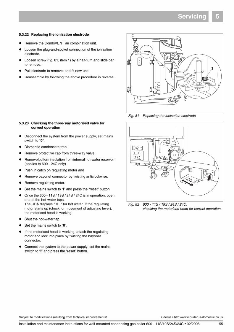
Servicing 5
Installation and maintenance instructions for wall-mounted condensing gas boiler 600 - 11S/19S/24S/24C • 02/2006 55
Subject to modifications resulting from technical improvements! Buderus • http://www.buderus-domestic.co.uk
5.3.22 Replacing the ionisation electrode
Remove the CombiVENT air combination unit.
Loosen the plug-and-socket connection of the ionization electrode.
Loosen screw (fig. 81, item 1) by a half-turn and slide bar to remove.
Pull electrode to remove, and fit new unit.
Reassemble by following the above procedure in reverse.
5.3.23 Checking the three-way motorised valve for correct operation
Disconnect the system from the power supply, set mains switch to "0".
Dismantle condensate trap.
Remove protective cap from three-way valve.
Remove bottom insulation from internal hot-water reservoir (applies to 600 - 24C only).
Push in catch on regulating motor and
Remove bayonet connector by twisting anticlockwise.
Remove regulating motor.
Set the mains switch to “I” and press the “reset” button.
Once the 600 - 11S / 19S / 24S / 24C is in operation, open one of the hot-water taps. The UBA displays " =. " for hot water. If the regulating motor starts up (check for movement of adjusting lever), the motorised head is working.
Shut the hot-water tap.
Set the mains switch to “0”.
If the motorised head is working, attach the regulating motor and lock into place by twisting the bayonet connector.
Connect the system to the power supply, set the mains switch to “I” and press the “reset” button.
Fig. 81 Replacing the ionisation electrode
�
Fig. 82 600 - 11S / 19S / 24S / 24C: checking the motorised head for correct operation

Servicing5
56 Installation and maintenance instructions for wall-mounted condensing gas boiler 600 - 11S/19S/24S/24C • 02/2006
Buderus • http://www.buderus-domestic.co.uk Subject to modifications resulting from technical improvements!
5.3.24 Replacing the motorised valve body control valve
Shut the servicing valve and drain the 600 - 11S / 19S / 24S / 24C as per the "Installation and Servicing Instructions".
Dismantle condensate trap.
Remove protective cap from three-way valve.
Remove bottom insulation from internal hot-water reservoir (applies to 600 - 24 C only).
Push in catch on regulating motor and remove bayonet connector by twisting anticlockwise.
Remove regulating motor.
Remove the control valve with a spanner and fit a new unit (fig. 83).
Fit regulating motor and lock into place by twisting the bayonet connector.
Reconnect the cable plug.
Set the mains switch to “I” and press the “reset” button.
5.3.25 Replacing the three-way valve
Shut the servicing valve and drain the 600 - 11S / 19S / 24S / 24C as per the "Installation and Servicing Instructions".
Dismantle condensate trap.
Remove protective cap from three-way valve.
Remove bottom insulation from internal hot-water reservoir (applies to 600 - 24 C only).
Push in catch on motorised valve head and remove bayonet connector by twisting anticlockwise.
Remove motorised head.
Loosen the 3 compression nuts (fig. 84).
Remove three-way valve and fit new unit.
Tighten the 3 compression nuts.
Fit motorised valve head and lock into place by twisting the bayonet connector.
Reconnect the cable plug.
Fig. 83 600 - 11S / 19S / 24S / 24C: replacing the control valve
NOTEOpen servicing valves, fill the 600 - 11S / 19S / 24S / 24C and purge the system of air.
Fig. 84 600 - 11S / 19S / 24S / 24C: replacing the three-way valve
A
B AB
NOTEReplace the three-way valve only if leaking occurs on the screw-in pipe connectors.A: Mains water, B: Heating, AB: Boiler flow line
NOTEOpen servicing valves, fill the 600 - 11S / 19S / 24S / 24C and purge the system of air.

Servicing 5
Installation and maintenance instructions for wall-mounted condensing gas boiler 600 - 11S/19S/24S/24C • 02/2006 57
Subject to modifications resulting from technical improvements! Buderus • http://www.buderus-domestic.co.uk
Connect the system to the power supply, set the mains switch to “I” and press the “reset” button.
5.3.26 Checking the ERC/RC connections to the UBA
Disconnect the system from the power supply.
Loosen crosshead screw on UBA housing.
Swivel the UBA housing downwards (fig. 85).
Push in UBA housing on left-hand side and open to the right (fig. 86).
Check to ensure that ERC or RC are correctly connected to 3 and 4.
Terminals 1 and 2 should not be wired in any way.The unit is supplied with a dummy connector between terminals 1 and 2 (fig. 87). The DC voltage at terminals 3 and 4 should be approx. 11.5 V. If this is not so, the UBA or the cable harness is defective.
Shut the UBA housing once more.
Swivel the UBA housing upwards and screw into place.
Connect system to mains power supply.
Set the mains switch to “I” and press the “reset” button.
5.3.27 Replacing the terminal strip
Note order of cable terminals. Loosen all cables.
Connect the cables, in the right order, to the new terminal strip.
Fig. 85 Swivel UBA housing downwards
Fig. 86 Opening the UBA housing

Servicing5
58 Installation and maintenance instructions for wall-mounted condensing gas boiler 600 - 11S/19S/24S/24C • 02/2006
Buderus • http://www.buderus-domestic.co.uk Subject to modifications resulting from technical improvements!
5.3.28 Checking connections at the ModuLink or iRT
Check contact link between cable and ModuLink or iRT.
There should be a DC voltage of approx. 11.5 V at the ModuLink or iRT.
5.3.29 Checking KIM connections
Locate KIM on boiler frame under UBA housing.
Check 4 pin connector (fig. 88, item 1) is fitted and secure.
Fig. 87 Checking the controller-device connections at the boiler
Key to control-device connections:
Item 1: ON/OFF temperature controller
Item 2: ModuLink or iRT room temperature controller (digital)
Item 3: I/O port / communication port
Item 4: Outdoor-temperature sensor
Item 5: Power supply 24 VAC/max. 6 VA
Item 6: Turn-on voltage for three-way valve (9+11)
1
2
3
4
5
6
NOTEIt is possible, in order to limit the source of errors, to disconnect the ModuLink or iRT from the boiler (bridge required at 3 and 4) and to install a conductor bridge at 1 and 2 (fig. 87).The heating and hot-water requirement is then passed via the potentiometer setting of the UBA.
Fig. 88 KIM connections
1
NOTEThis is not a serviceable part and any faultidentified with this component, contact Buderus.

Changing to another type of gas 6
Installation and maintenance instructions for wall-mounted condensing gas boiler 600 - 11S/19S/24S/24C • 02/2006 59
Subject to modifications resulting from technical improvements! Buderus • http://www.buderus-domestic.co.uk
6 Changing to another type of gas
Switch off the heating boiler
Disconnect the system from the power supply.
Close the gas shutoff valve.
Loosen the fixing screw and remove cover.
Open snap locks (fig. 89, item 1) and remove combustion chamber cover.
Loosen union nut on gas valve assembly (fig. 90, item 4).
Release plug-in connection of fan power lead (fig. 90, item 1), burner-control unit fan control lead (fig. 90, item 2) and gas-burner assembly (fig. 90, item 3).
Push safety plate out of way (fig. 91, item 1).
Turn air suction tube and pull off from below.
Fig. 89 Open snap locks
1
1
WARNING!Work on components in contact with gas must only be carried out by a registered CORGI engineer.
Fig. 90 Loosen the union nut and remove the cable
Fig. 91 Remove safety plate
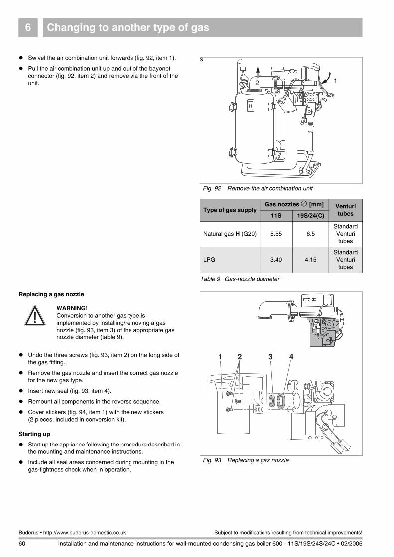
Changing to another type of gas6
60 Installation and maintenance instructions for wall-mounted condensing gas boiler 600 - 11S/19S/24S/24C • 02/2006
Buderus • http://www.buderus-domestic.co.uk Subject to modifications resulting from technical improvements!
sSwivel the air combination unit forwards (fig. 92, item 1).
Pull the air combination unit up and out of the bayonet connector (fig. 92, item 2) and remove via the front of the unit.
Replacing a gas nozzle
Undo the three screws (fig. 93, item 2) on the long side of the gas fitting.
Remove the gas nozzle and insert the correct gas nozzle for the new gas type.
Insert new seal (fig. 93, item 4).
Remount all components in the reverse sequence.
Cover stickers (fig. 94, item 1) with the new stickers (2 pieces, included in conversion kit).
Starting up
Start up the appliance following the procedure described in the mounting and maintenance instructions.
Include all seal areas concerned during mounting in the gas-tightness check when in operation.
Fig. 92 Remove the air combination unit
12
Type of gas supplyGas nozzles ∅ [mm] Venturi
tubes11S 19S/24(C)
Natural gas H (G20) 5.55 6.5Standard Venturi tubes
LPG 3.40 4.15Standard Venturi tubes
Table 9 Gas-nozzle diameter
Fig. 93 Replacing a gaz nozzle
WARNING!Conversion to another gas type is implemented by installing/removing a gas nozzle (fig. 93, item 3) of the appropriate gas nozzle diameter (table 9).
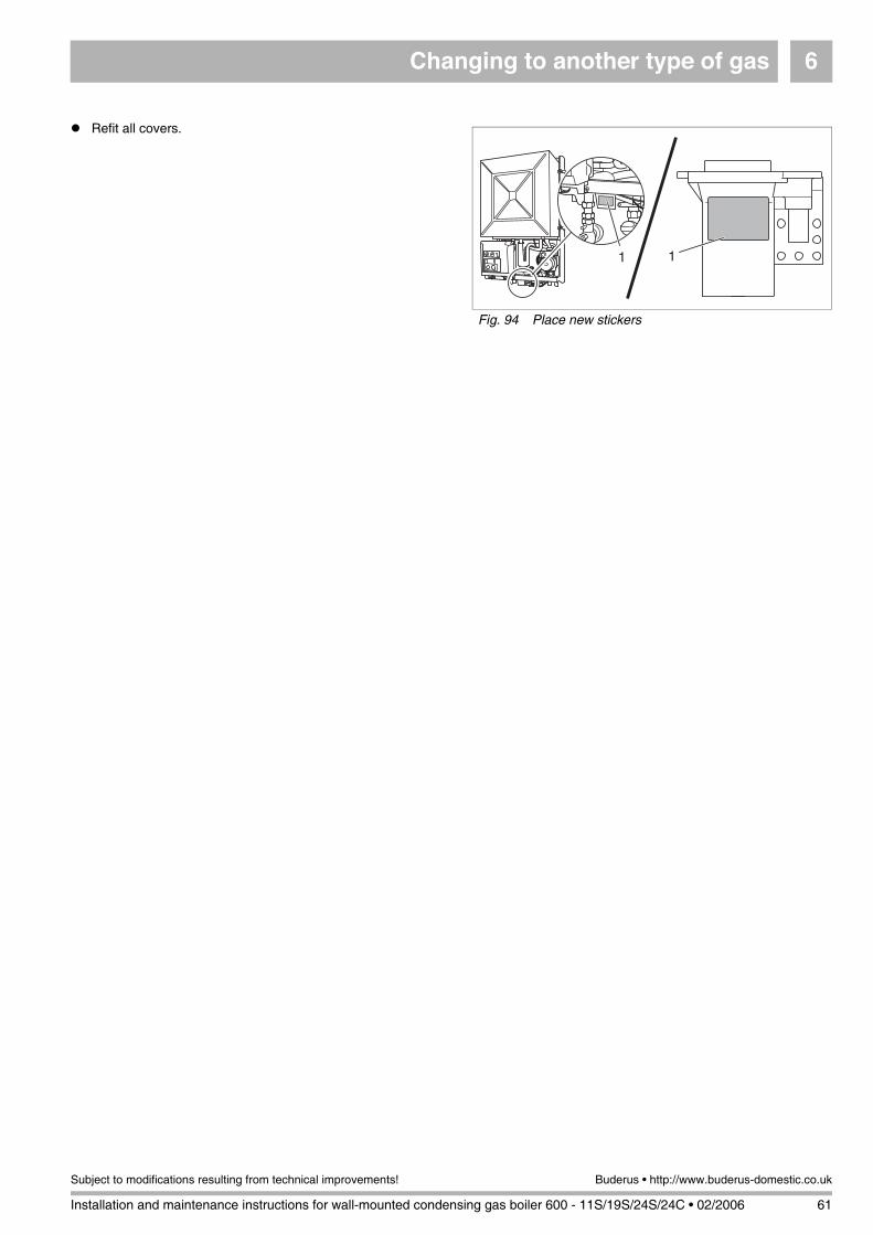
Changing to another type of gas 6
Installation and maintenance instructions for wall-mounted condensing gas boiler 600 - 11S/19S/24S/24C • 02/2006 61
Subject to modifications resulting from technical improvements! Buderus • http://www.buderus-domestic.co.uk
Refit all covers.
Fig. 94 Place new stickers
1 1
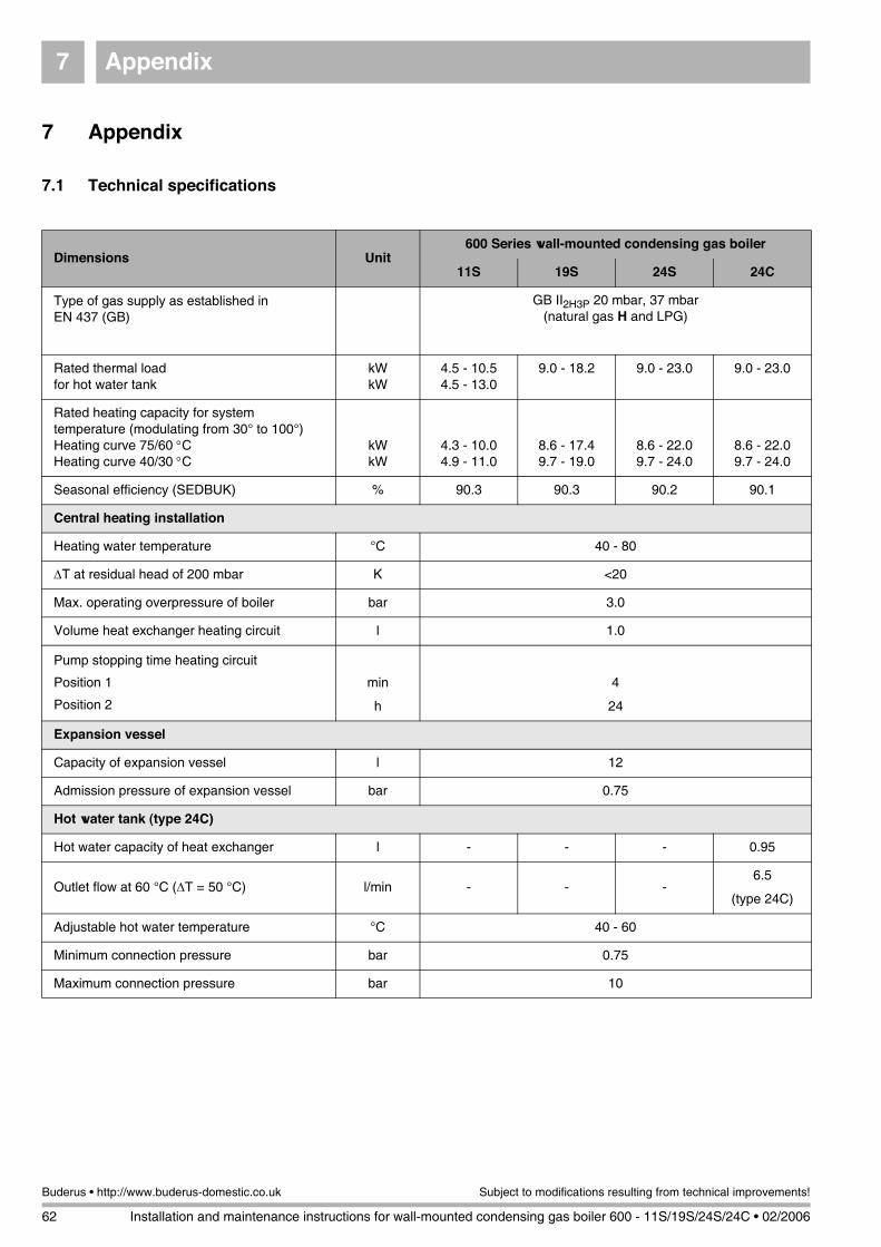
Appendix7
62 Installation and maintenance instructions for wall-mounted condensing gas boiler 600 - 11S/19S/24S/24C • 02/2006
Buderus • http://www.buderus-domestic.co.uk Subject to modifications resulting from technical improvements!
7 Appendix
7.1 Technical specifications
Dimensions Unit600 Series wall-mounted condensing gas boiler
11S 19S 24S 24C
Type of gas supply as established in EN 437 (GB)
GB II2H3P 20 mbar, 37 mbar(natural gas H and LPG)
Rated thermal loadfor hot water tank
kWkW
4.5 - 10.54.5 - 13.0
9.0 - 18.2 9.0 - 23.0 9.0 - 23.0
Rated heating capacity for system temperature (modulating from 30° to 100°)Heating curve 75/60 °CHeating curve 40/30 °C
kWkW
4.3 - 10.04.9 - 11.0
8.6 - 17.49.7 - 19.0
8.6 - 22.09.7 - 24.0
8.6 - 22.09.7 - 24.0
Seasonal efficiency (SEDBUK) % 90.3 90.3 90.2 90.1
Central heating installation
Heating water temperature °C 40 - 80
ΔT at residual head of 200 mbar K <20
Max. operating overpressure of boiler bar 3.0
Volume heat exchanger heating circuit l 1.0
Pump stopping time heating circuit
Position 1
Position 2
min
h
4
24
Expansion vessel
Capacity of expansion vessel l 12
Admission pressure of expansion vessel bar 0.75
Hot water tank (type 24C)
Hot water capacity of heat exchanger l - - - 0.95
Outlet flow at 60 °C (ΔT = 50 °C) l/min - - -6.5
(type 24C)
Adjustable hot water temperature °C 40 - 60
Minimum connection pressure bar 0.75
Maximum connection pressure bar 10
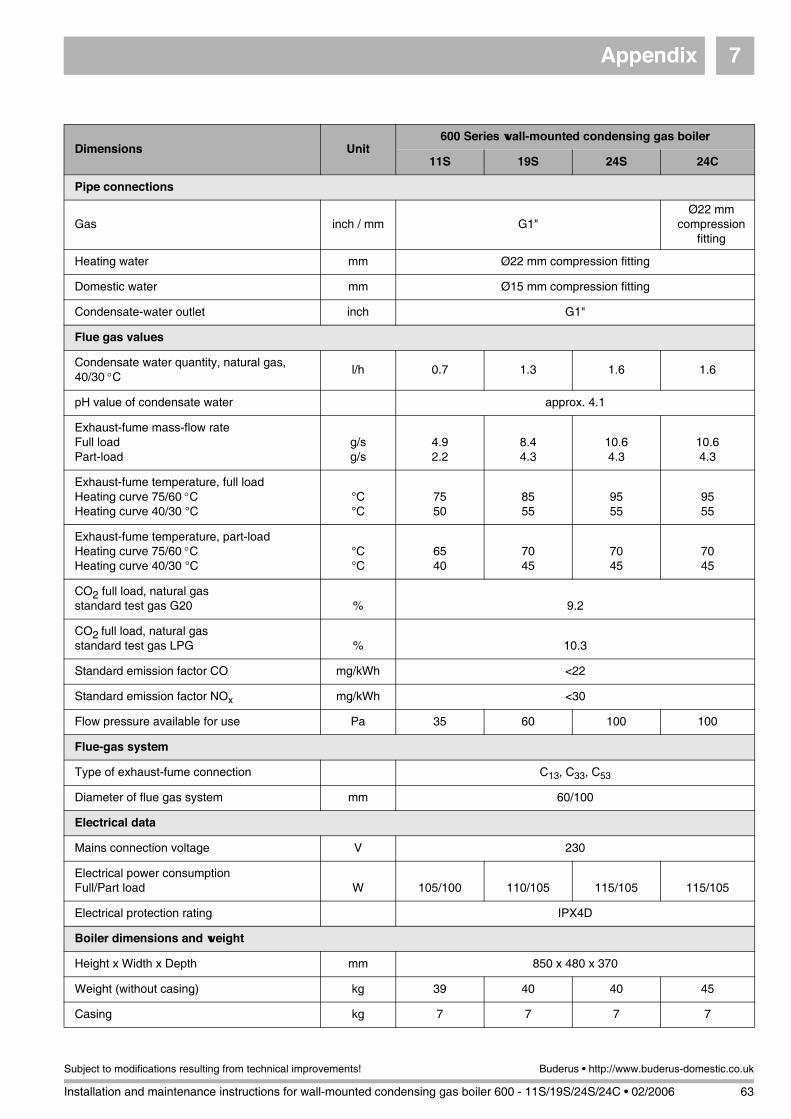
Appendix 7
Installation and maintenance instructions for wall-mounted condensing gas boiler 600 - 11S/19S/24S/24C • 02/2006 63
Subject to modifications resulting from technical improvements! Buderus • http://www.buderus-domestic.co.uk
Dimensions Unit600 Series wall-mounted condensing gas boiler
11S 19S 24S 24C
Pipe connections
Gas inch / mm G1"Ø22 mm
compression fitting
Heating water mm Ø22 mm compression fitting
Domestic water mm Ø15 mm compression fitting
Condensate-water outlet inch G1"
Flue gas values
Condensate water quantity, natural gas, 40/30 °C
l/h 0.7 1.3 1.6 1.6
pH value of condensate water approx. 4.1
Exhaust-fume mass-flow rateFull loadPart-load
g/sg/s
4.92.2
8.44.3
10.64.3
10.64.3
Exhaust-fume temperature, full loadHeating curve 75/60 °CHeating curve 40/30 °C
°C°C
7550
8555
9555
9555
Exhaust-fume temperature, part-loadHeating curve 75/60 °CHeating curve 40/30 °C
°C°C
6540
7045
7045
7045
CO2 full load, natural gas standard test gas G20 % 9.2
CO2 full load, natural gasstandard test gas LPG % 10.3
Standard emission factor CO mg/kWh <22
Standard emission factor NOx mg/kWh <30
Flow pressure available for use Pa 35 60 100 100
Flue-gas system
Type of exhaust-fume connection C13, C33, C53
Diameter of flue gas system mm 60/100
Electrical data
Mains connection voltage V 230
Electrical power consumptionFull/Part load W 105/100 110/105 115/105 115/105
Electrical protection rating IPX4D
Boiler dimensions and weight
Height x Width x Depth mm 850 x 480 x 370
Weight (without casing) kg 39 40 40 45
Casing kg 7 7 7 7
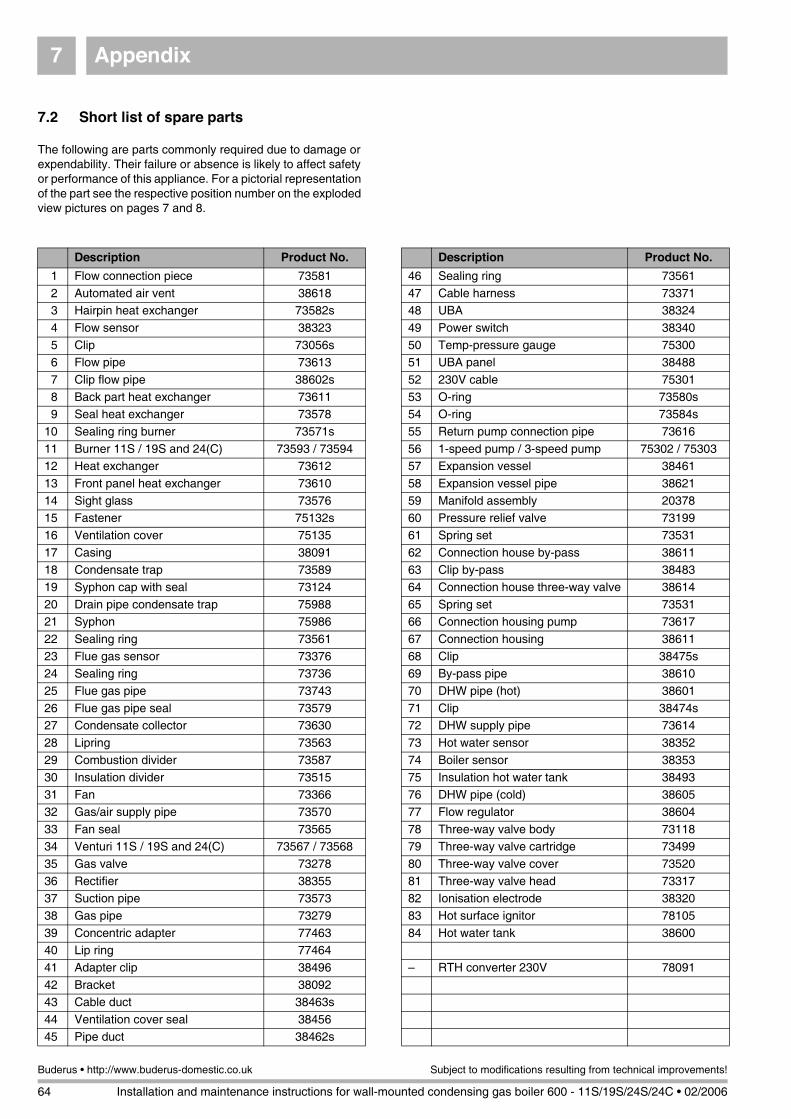
Appendix7
64 Installation and maintenance instructions for wall-mounted condensing gas boiler 600 - 11S/19S/24S/24C • 02/2006
Buderus • http://www.buderus-domestic.co.uk Subject to modifications resulting from technical improvements!
7.2 Short list of spare parts
The following are parts commonly required due to damage or expendability. Their failure or absence is likely to affect safety or performance of this appliance. For a pictorial representation of the part see the respective position number on the exploded view pictures on pages 7 and 8.
Description Product No.
46 Sealing ring 73561
47 Cable harness 7337148 UBA 38324
49 Power switch 38340
50 Temp-pressure gauge 7530051 UBA panel 38488
52 230V cable 75301
53 O-ring 73580s54 O-ring 73584s
55 Return pump connection pipe 73616
56 1-speed pump / 3-speed pump 75302 / 7530357 Expansion vessel 38461
58 Expansion vessel pipe 38621
59 Manifold assembly 2037860 Pressure relief valve 73199
61 Spring set 73531
62 Connection house by-pass 3861163 Clip by-pass 38483
64 Connection house three-way valve 38614
65 Spring set 7353166 Connection housing pump 73617
67 Connection housing 38611
68 Clip 38475s69 By-pass pipe 38610
70 DHW pipe (hot) 38601
71 Clip 38474s72 DHW supply pipe 73614
73 Hot water sensor 38352
74 Boiler sensor 38353
75 Insulation hot water tank 3849376 DHW pipe (cold) 38605
77 Flow regulator 38604
78 Three-way valve body 7311879 Three-way valve cartridge 73499
80 Three-way valve cover 73520
81 Three-way valve head 7331782 Ionisation electrode 38320
83 Hot surface ignitor 78105
84 Hot water tank 38600
– RTH converter 230V 78091
Description Product No.
1 Flow connection piece 73581
2 Automated air vent 386183 Hairpin heat exchanger 73582s
4 Flow sensor 38323
5 Clip 73056s6 Flow pipe 73613
7 Clip flow pipe 38602s
8 Back part heat exchanger 736119 Seal heat exchanger 73578
10 Sealing ring burner 73571s
11 Burner 11S / 19S and 24(C) 73593 / 7359412 Heat exchanger 73612
13 Front panel heat exchanger 73610
14 Sight glass 7357615 Fastener 75132s
16 Ventilation cover 75135
17 Casing 3809118 Condensate trap 73589
19 Syphon cap with seal 73124
20 Drain pipe condensate trap 7598821 Syphon 75986
22 Sealing ring 73561
23 Flue gas sensor 7337624 Sealing ring 73736
25 Flue gas pipe 73743
26 Flue gas pipe seal 7357927 Condensate collector 73630
28 Lipring 73563
29 Combustion divider 73587
30 Insulation divider 7351531 Fan 73366
32 Gas/air supply pipe 73570
33 Fan seal 7356534 Venturi 11S / 19S and 24(C) 73567 / 73568
35 Gas valve 73278
36 Rectifier 3835537 Suction pipe 73573
38 Gas pipe 73279
39 Concentric adapter 7746340 Lip ring 77464
41 Adapter clip 38496
42 Bracket 3809243 Cable duct 38463s
44 Ventilation cover seal 38456
45 Pipe duct 38462s
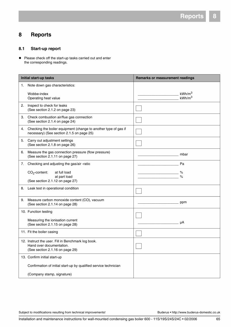
Reports 8
Installation and maintenance instructions for wall-mounted condensing gas boiler 600 - 11S/19S/24S/24C • 02/2006 65
Subject to modifications resulting from technical improvements! Buderus • http://www.buderus-domestic.co.uk
8 Reports
8.1 Start-up report
Please check off the start-up tasks carried out and enter the corresponding readings.
Initial start-up tasks Remarks or measurement readings
1. Note down gas characteristics:
Wobbe-indexOperating heat value
_____________________ kWh/m3
_____________________ kWh/m3
2. Inspect to check for leaks(See section 2.1.2 on page 23)
3. Check combustion air/flue gas connection(See section 2.1.4 on page 24)
4. Checking the boiler equipment (change to another type of gas if necessary) (See section 2.1.5 on page 25)
5. Carry out adjustment settings(See section 2.1.8 on page 26)
6. Measure the gas connection pressure (flow pressure)(See section 2.1.11 on page 27)
_____________________ mbar
7. Checking and adjusting the gas/air -ratio
CO2-content: at full loadat part load
(See section 2.1.12 on page 27)
_____________________ Pa
_____________________ %_____________________ %
8. Leak test in operational condition
9. Measure carbon monoxide content (CO), vacuum(See section 2.1.14 on page 28)
_____________________ ppm
10. Function testing
Measuring the ionisation current(See section 2.1.15 on page 28)
_____________________ µA
11. Fit the boiler casing
12. Instruct the user. Fill in Benchmark log book. Hand over documentation.(See section 2.1.16 on page 29)
13. Confirm initial start-up
Confirmation of initial start-up by qualified service technician
(Company stamp, signature)
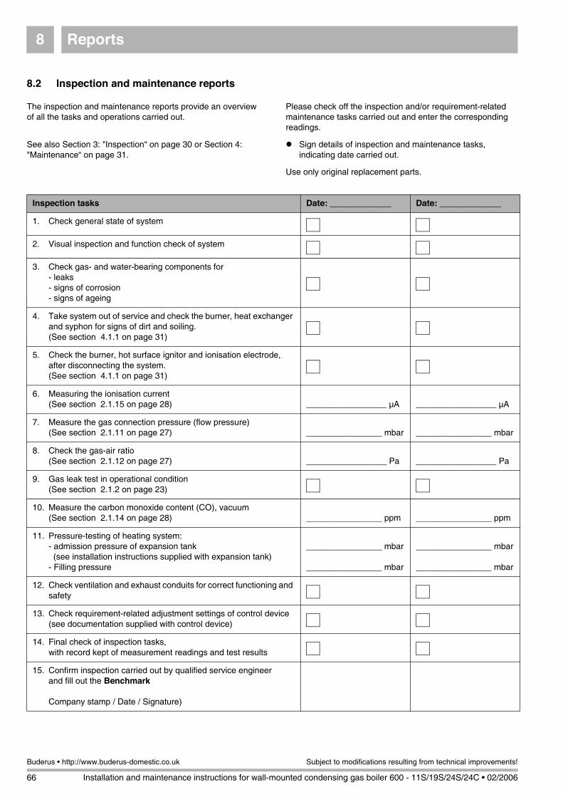
Reports8
66 Installation and maintenance instructions for wall-mounted condensing gas boiler 600 - 11S/19S/24S/24C • 02/2006
Buderus • http://www.buderus-domestic.co.uk Subject to modifications resulting from technical improvements!
8.2 Inspection and maintenance reports
Please check off the inspection and/or requirement-related maintenance tasks carried out and enter the corresponding readings.
The inspection and maintenance reports provide an overview of all the tasks and operations carried out.
Sign details of inspection and maintenance tasks, indicating date carried out.
See also Section 3: "Inspection“ on page 30 or Section 4: "Maintenance“ on page 31.
Use only original replacement parts.
Inspection tasks Date: _____________ Date: _____________
1. Check general state of system
2. Visual inspection and function check of system
3. Check gas- and water-bearing components for- leaks- signs of corrosion- signs of ageing
4. Take system out of service and check the burner, heat exchanger and syphon for signs of dirt and soiling. (See section 4.1.1 on page 31)
5. Check the burner, hot surface ignitor and ionisation electrode, after disconnecting the system.(See section 4.1.1 on page 31)
6. Measuring the ionisation current(See section 2.1.15 on page 28) _________________ µA _________________ µA
7. Measure the gas connection pressure (flow pressure)(See section 2.1.11 on page 27) ________________ mbar ________________ mbar
8. Check the gas-air ratio(See section 2.1.12 on page 27) _________________ Pa _________________ Pa
9. Gas leak test in operational condition(See section 2.1.2 on page 23)
10. Measure the carbon monoxide content (CO), vacuum(See section 2.1.14 on page 28) ________________ ppm ________________ ppm
11. Pressure-testing of heating system:- admission pressure of expansion tank(see installation instructions supplied with expansion tank)
- Filling pressure
________________ mbar
________________ mbar
________________ mbar
________________ mbar
12. Check ventilation and exhaust conduits for correct functioning and safety
13. Check requirement-related adjustment settings of control device(see documentation supplied with control device)
14. Final check of inspection tasks, with record kept of measurement readings and test results
15. Confirm inspection carried out by qualified service engineerand fill out the Benchmark
Company stamp / Date / Signature)
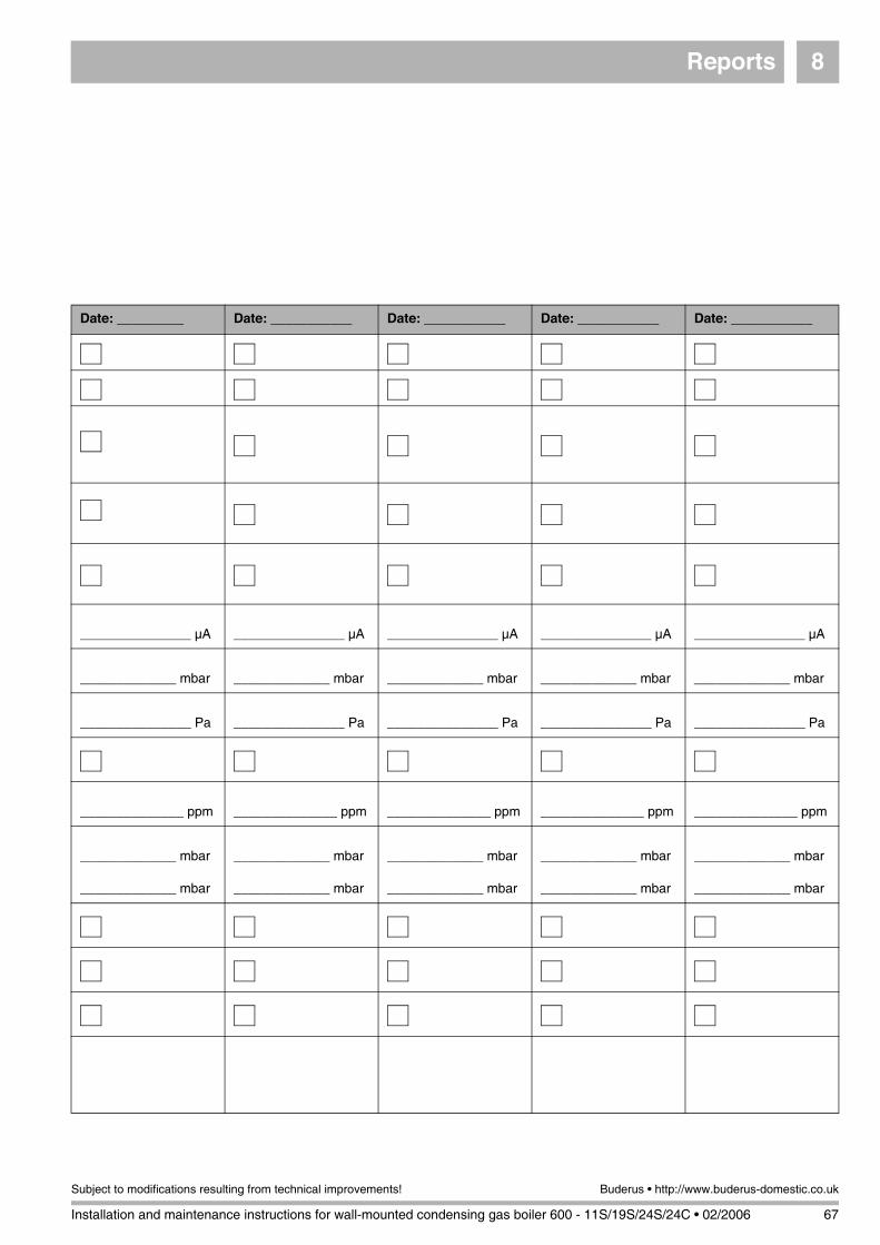
Reports 8
Installation and maintenance instructions for wall-mounted condensing gas boiler 600 - 11S/19S/24S/24C • 02/2006 67
Subject to modifications resulting from technical improvements! Buderus • http://www.buderus-domestic.co.uk
Date: _________ Date: ___________ Date: ___________ Date: ___________ Date: ___________
_______________ µA _______________ µA _______________ µA _______________ µA _______________ µA
_____________ mbar _____________ mbar _____________ mbar _____________ mbar _____________ mbar
_______________ Pa _______________ Pa _______________ Pa _______________ Pa _______________ Pa
______________ ppm ______________ ppm ______________ ppm ______________ ppm ______________ ppm
_____________ mbar
_____________ mbar
_____________ mbar
_____________ mbar
_____________ mbar
_____________ mbar
_____________ mbar
_____________ mbar
_____________ mbar
_____________ mbar
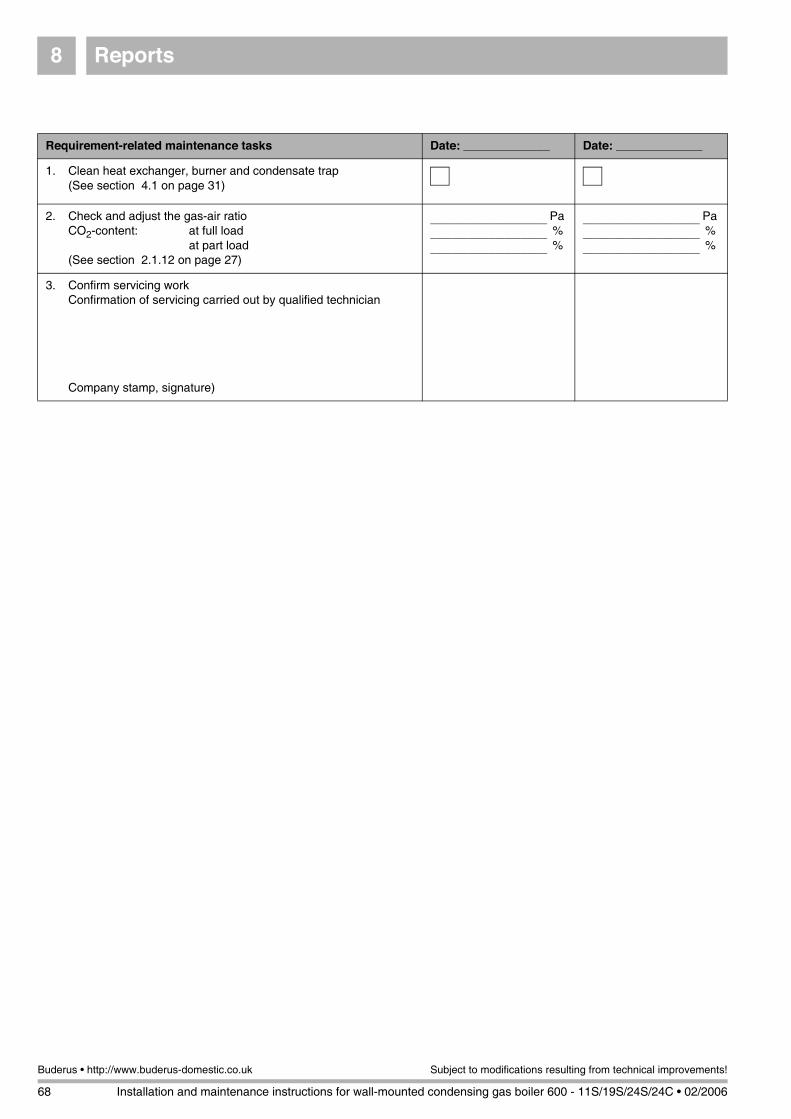
Reports8
68 Installation and maintenance instructions for wall-mounted condensing gas boiler 600 - 11S/19S/24S/24C • 02/2006
Buderus • http://www.buderus-domestic.co.uk Subject to modifications resulting from technical improvements!
Requirement-related maintenance tasks Date: _____________ Date: _____________
1. Clean heat exchanger, burner and condensate trap(See section 4.1 on page 31)
2. Check and adjust the gas-air ratioCO2-content: at full load
at part load(See section 2.1.12 on page 27)
______________________ Pa
______________________ %
______________________ %
______________________ Pa
______________________ %
______________________ %
3. Confirm servicing workConfirmation of servicing carried out by qualified technician
Company stamp, signature)
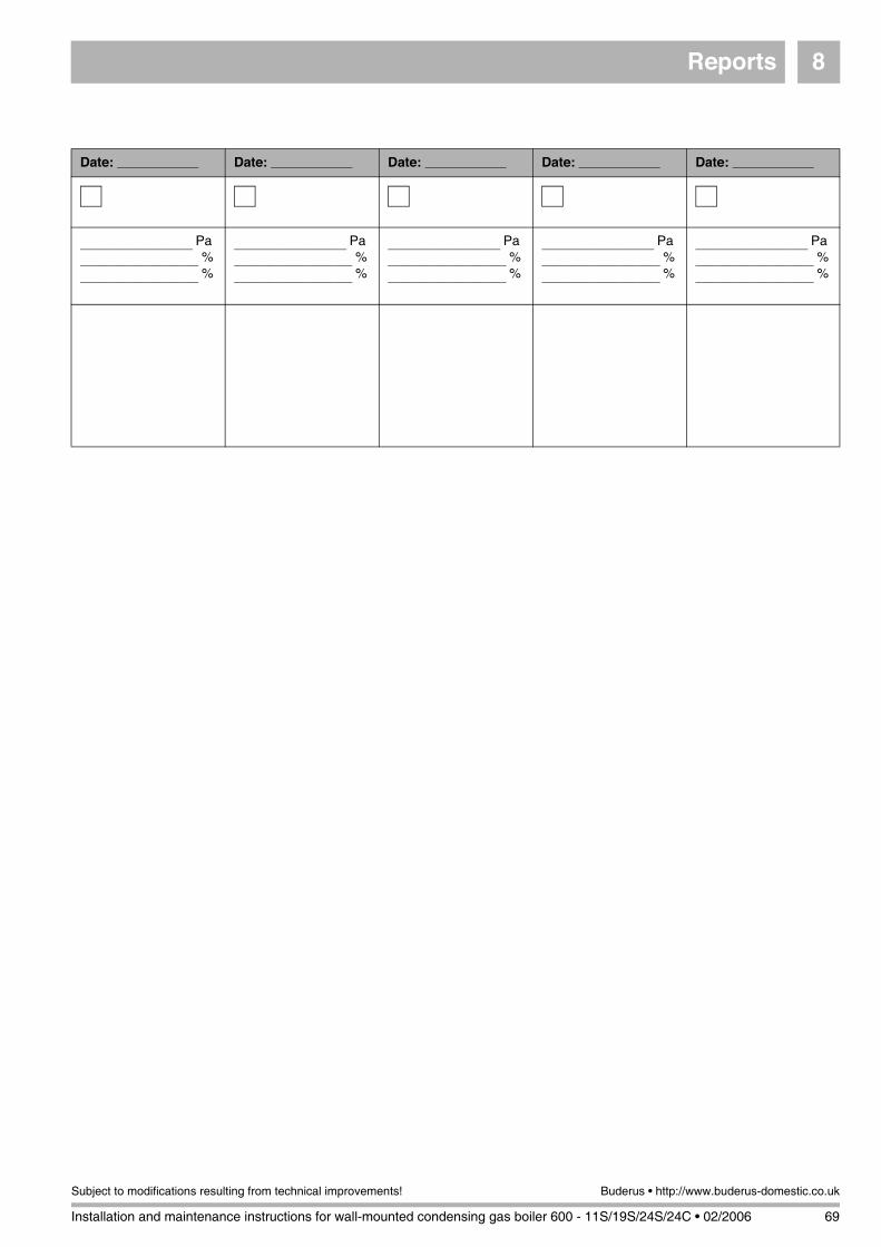
Reports 8
Installation and maintenance instructions for wall-mounted condensing gas boiler 600 - 11S/19S/24S/24C • 02/2006 69
Subject to modifications resulting from technical improvements! Buderus • http://www.buderus-domestic.co.uk
Date: ___________ Date: ___________ Date: ___________ Date: ___________ Date: ___________
___________________ Pa
____________________ %
____________________ %
___________________ Pa
____________________ %
____________________ %
___________________ Pa
____________________ %
____________________ %
___________________ Pa
____________________ %
____________________ %
___________________ Pa
____________________ %
____________________ %
Notes
70 Installation and maintenance instructions for wall-mounted condensing gas boiler 600 - 11S/19S/24S/24C • 02/2006
Buderus • http://www.buderus-domestic.co.uk Subject to modifications resulting from technical improvements!
Notes
Installation and maintenance instructions for wall-mounted condensing gas boiler 600 - 11S/19S/24S/24C • 02/2006 71
Subject to modifications resulting from technical improvements! Buderus • http://www.buderus-domestic.co.uk

Heating system specialist:
BuderusCotswold Way
WarndonWorcesterWR4 9SW
Telephone: 01905 - 752 936Fax: 01905 - 753 130
www.buderus-domestic.co.uk
Buderus is a trading name of BBT Thermotechnology UK Ltd.
Customer Services:
Technical Product Support:
Sales:
Returns:
Spares:
Tel: 0870 - 421 5933
Tel: 0870 - 421 5944
Tel: 01905 - 752 640
Tel: 01905 - 752 531
Tel: 01905 - 752 576
Fax: 01905 - 456 445 / 455 394
Fax: 01905 - 455 392
Fax: 01905 - 754 620 720.
967A
- 4
612
- 02
/200
6