installation and commissioning manual 1mrs751265-men installation and commissioning manual sms 510...
TRANSCRIPT

SMS 510
Installation and Commissioning Manual


Installation and Commissioning Manual
SMS 5101MRS751265-MEN
Issued: 31.01.2000Version: C/31.08.2004
1. About this manual .....................................................................91.1. Copyrights .....................................................................................91.2. Trademarks ...................................................................................91.3. General .........................................................................................91.4. Related documents .....................................................................101.5. Document revisions .....................................................................10
2. Introduction to SMS 510 .........................................................112.1. Software ......................................................................................11
2.1.1. SMS 510 installation applications ....................................112.2. Documentation ............................................................................122.3. Hardware .....................................................................................13
3. Requirements ..........................................................................153.1. SMS 510 requirements ...............................................................15
3.1.1. Software requirements .....................................................153.1.2. Hardware requirements ...................................................153.1.3. Additional requirements ...................................................16
4. Installation ...............................................................................174.1. Preparing your computer for the SMS 510 installation ................17
4.1.1. Install-time user account ..................................................174.1.2. Operating system software ..............................................17
4.2. Overview .....................................................................................174.2.1. Current version of the product .........................................174.2.2. Non-forced installation .....................................................174.2.3. Forced installation ............................................................174.2.4. License of the product ......................................................184.2.5. Applications running at install-time ..................................184.2.6. System-wide product interdependencies .........................18
4.2.6.1. Multiple installations of the kernel software ........184.2.6.2. MicroSCADA service ..........................................184.2.6.3. MicroSCADA user account ................................184.2.6.4. Kernel incompatibility issues ..............................19
4.3. Software installation procedure outlined .....................................194.3.1. Overview ..........................................................................194.3.2. Main SMS 510 installation ...............................................204.3.3. Installation of other software ............................................21
4.4. Installing the software .................................................................214.4.1. Starting the main installation ............................................214.4.2. Installation Wizard ............................................................22
4.4.2.1. Welcome ............................................................224.4.2.2. Product License Agreement ...............................23
©Copyright 2004 ABB Oy, Distribution Automation, Vaasa, FINLAND 3

1MRS751265-MEN
Installation and Commissioning Manual
SMS 510
4.4.2.3. System Information 1 ......................................... 244.4.2.4. System Information 2 ........................................ 254.4.2.5. System Information 3 ........................................ 264.4.2.6. Select - forced installation .................................. 274.4.2.7. Select - non-forced installation .......................... 284.4.2.8. Destination Drive ............................................... 294.4.2.9. Installing ............................................................. 304.4.2.10.MicroSCADA user account ................................ 304.4.2.11.MicroSCADA Service Access Manager ............. 314.4.2.12.Installation completed ........................................ 334.4.2.13.System reboot ................................................... 34
4.4.3. Cancelling the installation ................................................ 344.5. Installing the Parameter Setting Tool software ........................... 34
4.5.1. Starting the PST installation ............................................ 354.6. Installing the CAP 2/316 software ............................................... 35
4.6.1. Starting the CAP 2/316 installation .................................. 354.7. Installing the REB500 Selector software .................................... 35
4.7.1. Starting the REB500 Selector installation ........................ 354.8. Installing the HMI500 - REBWIN software .................................. 36
4.8.1. Starting the HMI500 - REBWIN installation ..................... 364.9. SMS 510 program folder ............................................................. 37
4.9.1. Subfolder - Doc ................................................................ 374.9.2. Subfolder - Setup ............................................................ 384.9.3. Subfolder - Tools ............................................................ 394.9.4. Shortcut to the SMS 510 program folder ......................... 39
5. Commissioning ...................................................................... 415.1. Commissioning tasks .................................................................. 415.2. Licensing the product - License tool ........................................... 41
5.2.1. General ............................................................................ 415.2.2. License Information dialog ............................................... 425.2.3. Entering license information ............................................ 425.2.4. Invalid license information ............................................... 44
5.3. Communication support .............................................................. 445.3.1. Communication protocol support ..................................... 445.3.2. Communication channels ................................................ 455.3.3. Serial port communication ............................................... 45
5.3.3.1. SMS 510 vs. operating system’s serial port configuration ...................................................... 45
5.3.3.2. Using USB ports ................................................ 455.3.4. LON communication ........................................................ 46
5.3.4.1. LON communication adapters ....................... 46
4

1MRS751265-MEN SMS 510 Installation and Commissioning Manual
5.3.4.2. LON communication software components .......465.3.5. Time synchronization .......................................................46
5.3.5.1. Overview ............................................................465.3.5.2. Time synchronization over LON protocol ...........465.3.5.3. Time synchronization over SPA protocol ...........47
5.3.6. Procedure for commissioning communication components .....................................................................47
5.4. System Configuration Tool ..........................................................475.4.1. Overview ..........................................................................47
5.4.1.1. Scheduler ...........................................................485.4.1.2. General Settings ................................................485.4.1.3. Communication configuration .............................48
5.4.2. Starting .............................................................................485.4.3. System Configuration tool dialog ....................................48
5.4.3.1. Serial Ports page ................................................505.4.3.2. Serial ports - Adding ...........................................515.4.3.3. Serial ports - Configuring ...................................525.4.3.4. Serial ports - Deleting ........................................535.4.3.5. LON page ...........................................................535.4.3.6. Selecting the adapter .........................................545.4.3.7. Assigning Subnet/Node settings ........................55
5.4.4. Saving system configuration ............................................585.4.4.1. Save configuration - close tool ...........................585.4.4.2. Save configuration - proceed configuration ........585.4.4.3. Discard configuration changes ...........................59
5.5. Installing LON cards ....................................................................595.5.1. PCC-10 PC Card commissioning procedure ...................595.5.2. PCLTA-20 Card commissioning procedure .....................59
5.5.2.1. Installation of the PCLTA-20 adapter to Windows 2000 or Windows XP ..........................................59
5.5.3. PCC-10 PC Card configuration .......................................635.5.3.1. Device driver installation ....................................635.5.3.2. PCC-10 initial configuration ................................65
5.5.4. PCLTA-20 Card configuration .........................................685.5.4.1. Device driver installation ....................................685.5.4.2. PCLTA-20 initial configuration ............................70
5.6. Troubleshooting LON ..................................................................745.6.1. PCC-10 PC Card preferences .........................................745.6.2. LON channel configuration failure ....................................755.6.3. Recovering from failure to configure PCLTA Card
channels............................................................................76
5

1MRS751265-MEN
Installation and Commissioning Manual
SMS 510
5.7. CAP2/316 - Distributed COM identity ......................................... 785.7.1. Overview .......................................................................... 785.7.2. When to apply the DCOM identity ................................... 795.7.3. DCOM identity configuration ............................................ 79
5.8. RAS/Modem installation on Windows NT ................................... 845.8.1. Overview .......................................................................... 845.8.2. Installing modems ............................................................ 855.8.3. Installing Remote Access Service ................................... 885.8.4. Installing MS Loopback Adapter driver ............................ 915.8.5. Considerations when specifying IP addresses ................ 945.8.6. Configuring start-up of Remote Access Server service ... 955.8.7. Verifying Remote Access Server service ......................... 965.8.8. Configuring dial-in permissions in the RAS server
computer 965.9. RAS/Modem installation on Windows 2000 ................................ 98
5.9.1. Considerations when specifying IP addresses in Windows 2000 111
5.10.RAS/Modem installation on Windows XP ................................ 1125.10.1.Considerations when specifying IP addresses in
Windows XP .................................................................. 1285.11.About phonebooks and SMS 510 ............................................ 1295.12.Dialing-Up in SMS 510 ............................................................. 1295.13.Configuring SMS 510 start-up .................................................. 129
5.13.1.Avoiding virtual memory overlap at SMS 510 start-up ... 129
6. Uninstallation ........................................................................ 1316.1. Overview ................................................................................... 1316.2. Features .................................................................................... 1316.3. Scope of uninstallation .............................................................. 1316.4. Preparing for uninstallation ....................................................... 1316.5. Backing up the data .................................................................. 1326.6. Cancelling/aborting the uninstallation ....................................... 1326.7. Starting the uninstallation ......................................................... 1326.8. Uninstall Wizard ........................................................................ 133
6.8.1. Overview ........................................................................ 1336.8.2. Uninstall Wizard dialogs ................................................ 133
6.8.2.1. Welcome to Uninstall ....................................... 1336.8.2.2. Backup Notice .................................................. 1346.8.2.3. Ready to Uninstall ............................................ 1356.8.2.4. Uninstall in Progress ........................................ 1356.8.2.5. Uninstall Completed ......................................... 136
6.9. Rebooting ................................................................................. 137
6

1MRS751265-MEN SMS 510 Installation and Commissioning Manual
6.10.Troubleshooting ........................................................................137
7. Troubleshooting installation ................................................1397.1. Incorrect operating system detected .........................................1397.2. Incorrect operating system version detected ............................1397.3. Insufficient user rights to install .................................................1397.4. MicroSCADA service is running ................................................1397.5. Failing to install the MicroSCADA service .................................1407.6. Troubleshooting destination drive error messages ..................1417.7. Insufficient disk space ...............................................................1417.8. No suitable destination drive available ......................................1417.9. Incompatible SYS 500 and/or COM 500 installed .....................1427.10.Galaxy Debug window during first start-up ...............................1437.11.CAP 2/316 does not start .........................................................1437.12.Error when opening Remote Connection Properties dialog .....1437.13.Miscellaneous ...........................................................................143
7.13.1.Repaired operating system installations ........................1437.13.2.TEMP environment variable ...........................................144
8. Index .......................................................................................149
7


1MRS751265-MEN SMS 510 Installation and Commissioning Guide
1. About this manual
1.1. CopyrightsThe information in this document is subject to change without notice and should not be construed as a commitment by ABB Oy. ABB Oy assumes no responsibility for any errors that may appear in this document.
In no event shall ABB Oy be liable for direct, indirect, special, incidental or consequential damages of any nature or kind arising from the use of this document, nor shall ABB Oy be liable for incidental or consequential damages arising from use of any software or hardware described in this document.
This document and parts thereof must not be reproduced or copied without written permission from ABB Oy, and the contents thereof must not be imparted to a third party nor used for any unauthorized purpose.
The software or hardware described in this document is furnished under a license and may be used, copied, or disclosed only in accordance with the terms of such license.
Copyright © 2004 ABB Oy All rights reserved.
1.2. TrademarksRegistrations and trademarks used in this document include:
Intel and Pentium are registered trademarks of Intel Corporation.
Acrobat is a registered trademark of Adobe Corporation.
Neuron is a registered trademark of Echelon Corporation.
LON is a registered trademark of Echelon Corporation.
All Microsoft products referenced in this document are either trademarks or registered trademarks of Microsoft Corporation.
Other brand or product names are trademarks or registered trademarks of their respective holders.
1.3. GeneralThis document complies with the SMS version 1.2.0.
Additional information such as Release Notes and Last Minute Remarks can be found on the program distribution media.
ABB Oy, Distribution Automation regularly provides standard training courses on its main products.The training program is available on the Internet at http://www.abb.com/substationautomation. Contact your ABB contact for more information.
Futhermore, pictures shown are examples only.
9
1MRS751265-MEN
Installation and Commissioning Guide
SMS 510
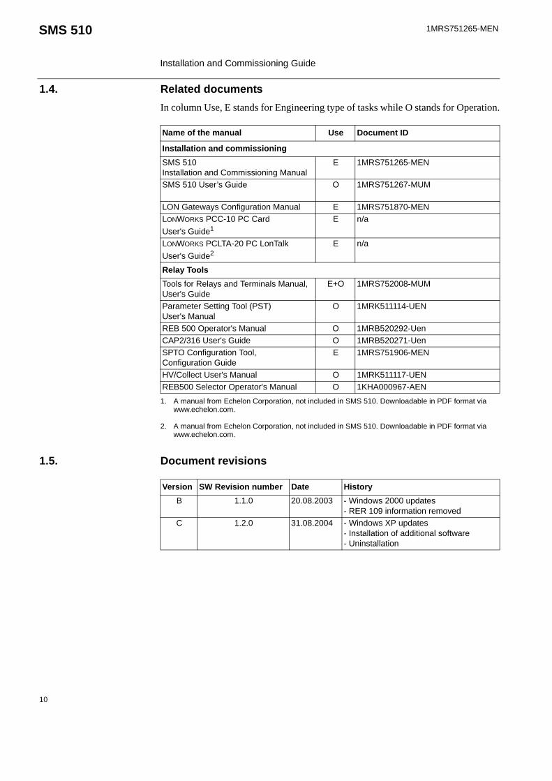
1.4. Related documentsIn column Use, E stands for Engineering type of tasks while O stands for Operation.
1.5. Document revisions
Name of the manual Use Document ID
Installation and commissioningSMS 510 Installation and Commissioning Manual
E 1MRS751265-MEN
SMS 510 User’s Guide O 1MRS751267-MUM
LON Gateways Configuration Manual E 1MRS751870-MENLONWORKS PCC-10 PC Card User's Guide1
1. A manual from Echelon Corporation, not included in SMS 510. Downloadable in PDF format via www.echelon.com.
E n/a
LONWORKS PCLTA-20 PC LonTalk User's Guide2
2. A manual from Echelon Corporation, not included in SMS 510. Downloadable in PDF format via www.echelon.com.
E n/a
Relay Tools Tools for Relays and Terminals Manual, User's Guide
E+O 1MRS752008-MUM
Parameter Setting Tool (PST) User's Manual
O 1MRK511114-UEN
REB 500 Operator's Manual O 1MRB520292-UenCAP2/316 User's Guide O 1MRB520271-UenSPTO Configuration Tool, Configuration Guide
E 1MRS751906-MEN
HV/Collect User's Manual O 1MRK511117-UENREB500 Selector Operator's Manual O 1KHA000967-AEN
Version SW Revision number Date HistoryB 1.1.0 20.08.2003 - Windows 2000 updates
- RER 109 information removedC 1.2.0 31.08.2004 - Windows XP updates
- Installation of additional software- Uninstallation
10
1MRS751265-MEN SMS 510 Installation and Commissioning Manual
2. Introduction to SMS 510
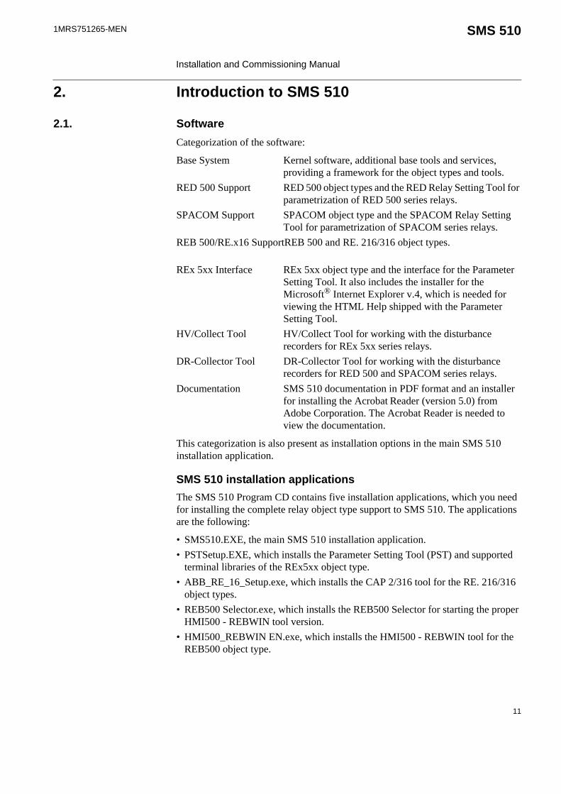
2.1. SoftwareCategorization of the software:
Base System Kernel software, additional base tools and services, providing a framework for the object types and tools.
RED 500 Support RED 500 object types and the RED Relay Setting Tool for parametrization of RED 500 series relays.
SPACOM Support SPACOM object type and the SPACOM Relay Setting Tool for parametrization of SPACOM series relays.
REB 500/RE.x16 SupportREB 500 and RE. 216/316 object types.
REx 5xx Interface REx 5xx object type and the interface for the Parameter Setting Tool. It also includes the installer for the Microsoft® Internet Explorer v.4, which is needed for viewing the HTML Help shipped with the Parameter Setting Tool.
HV/Collect Tool HV/Collect Tool for working with the disturbance recorders for REx 5xx series relays.
DR-Collector Tool DR-Collector Tool for working with the disturbance recorders for RED 500 and SPACOM series relays.
Documentation SMS 510 documentation in PDF format and an installer for installing the Acrobat Reader (version 5.0) from Adobe Corporation. The Acrobat Reader is needed to view the documentation.
This categorization is also present as installation options in the main SMS 510 installation application.
SMS 510 installation applicationsThe SMS 510 Program CD contains five installation applications, which you need for installing the complete relay object type support to SMS 510. The applications are the following:
• SMS510.EXE, the main SMS 510 installation application.• PSTSetup.EXE, which installs the Parameter Setting Tool (PST) and supported
terminal libraries of the REx5xx object type.• ABB_RE_16_Setup.exe, which installs the CAP 2/316 tool for the RE. 216/316
object types.• REB500 Selector.exe, which installs the REB500 Selector for starting the proper
HMI500 - REBWIN tool version.• HMI500_REBWIN EN.exe, which installs the HMI500 - REBWIN tool for the
REB500 object type.
11

1MRS751265-MEN
Installation and Commissioning Manual
SMS 510
2.2. DocumentationThe SMS 510 delivery contains the documentation in electronic format only. The manuals are listed below:
Notes about the installation of additional software:• PST needs to be installed only if REx 5xx object types are used.• CAP 2/316 needs to be installed only if RE. 216/316 object types are
used.• REB500 Selector and HMI500 - REBWIN need to be installed only if
REB500 object types are used.• If newer or other versions of the additional software mentioned above
are available, the applicable tools can be installed to SMS 510. In this case the new installation must be carried out with caution to proper folders.
Table 2.2.-1 SMS 510 manuals
Manual DescriptionSMS 510Installation and Commissioning Manual
Provides installation and commissioning instructions for the SMS 510 software.
SMS 510User’s Guide
Provides information on using the base system functions of SMS 510.
Tools for Relays and Terminals(User’s Guide)
Provides information on the Relay Setting tools, DR-Collector Tool, SPA Terminal Emulator, Disturbance Draw Tool, Power Quality Monitoring Tool, RED and SPACOM object types.
LON GatewaysConfiguration Guide
Provides information on using the communication gateway object types.
SPTO Configuration Tool User’s Guide
Provides information on monitoring and configuring of the SPTO 1D2, 1D5, 1D6 and 6D3 control modules in the SPAC feeder terminal series.
REB 500 Selector Operator's Manual
Operator's Manual for the REB 500 Selector
REB 500Operator's Manual
Operator's Manual for the REBWIN HMI tool.
Getting Started CAP2/316 Provides information on using the CAP2/316 tool.
PSTUser's Manual
User's Manual for the Parameter Setting Tool (PST).
HV/CollectUser’s Manual
User's Manual for the HV/Collect Tool.
12

1MRS751265-MEN SMS 510 Installation and Commissioning Manual
2.3. HardwareThe communication cables listed in the following table are regarded as accessories and are not included in the SMS 510 delivery. They can be acquired by placing a separate order.
Table 2.3.-1 Communication hardware
Relay Type Order numberREF 541, 543, 545REM 543, 545REX 521REJ 51_ / 52_REU 513, 523
Opto 1MKC950001-1
REC 523 1MRS120520REM 610 Opto.
*Contact your nearest ABB representative for availability.
1MRS050698*
SPTO front connectorSPCR front connector
RS 232 - RS 232 SPA-ZP 17A3
SPACOM 100/300 series RS 232 - TTL connector SPA-ZP 5A3SPAC 300/500/600 rear RS 232 - RS 485 SPA-ZP 6A2SACO 16A3, 16D1, 16D3 and 64D4
*Connection cable for SPA-ZP 6A2 to SACO screw terminal
SPA-ZP 21A* andSPA-ZP 6A2
13


1MRS751265-MEN SMS 510 Installation and Commissioning Manual
3. Requirements
This chapter describes the requirements for installing the SMS 510 software.
3.1. SMS 510 requirementsSMS 510 v. 1.2.0 sets the following hardware and software requirements on the PC. Notice also the kernel-related dependencies explained in Section “System-wide product interdependencies” on page 18.
3.1.1. Software requirementsThe following table lists the software requirements set by SMS 510.
3.1.2. Hardware requirementsThe following table lists the hardware requirements set by SMS 510.
Table 3.1.1-1 SMS 510 software requirements
Item RequiredOperating system Microsoft Windows NT 4.0 Workstation
Microsoft Windows 2000
Microsoft Windows XP* It is highly recommended to have the latest Service Pack installed.
Network Network software.Network Protocol Transport Control Protocol/Internet Protocol (TCP/IP).Remote Access Service (RAS) Installation of RAS to enable remote connections from
SMS 510 to SMS 510, SYS 500 and COM 500.Microsoft Internet Explorer Version 4 or higher to be capable of viewing the HTML
help shipped with the PST tool.
Table 3.1.2-1 SMS 510 hardware requirements
Item Minimum RecommendedProcessor 233 MHz or higher Pentium
compatible CPU1 GHz or higher Pentium compatible CPU
Memory 128 MB 256 MBDisplay SVGA, 800x600, 256 colours SVGA, 1024x768, 256 coloursFile system NTFS file system on the installation
driveHard disk space 300 MB 500 MBCD-ROM drive Any device supported by the
operating system. Required for installation
Mouse Any device supported by the operating system
PCI slots One slot for each PCLTA-20 cardPCMCIA slots One slot for each PCC-10 cardNetwork adapter card
Any device supported by the operating system
15

1MRS751265-MEN
Installation and Commissioning Manual
SMS 510
3.1.3. Additional requirementsThe following table lists the additional requirements set by SMS 510.
Modem Any Hayes compatible modem supported by the operating system.
Table 3.1.2-1 SMS 510 hardware requirements
Item Minimum Recommended
Table 3.1.3-1 Additional requirements
Item DescriptionUser account You must be logged on to the operating system with administrator
rights in order to install the software successfully. Otherwise the installation is denied.
MicroSCADA service
The MicroSCADA service is not allowed to run in the background during the installation. Otherwise the installation is denied.
16

1MRS751265-MEN SMS 510 Installation and Commissioning Manual
4. Installation
This chapter describes the software installation procedure of SMS 510.
4.1. Preparing your computer for the SMS 510 installationIt is highly recommended that you make the following preparations before you install SMS 510.
4.1.1. Install-time user accountEnsure that you are able to logon to the computer from a user account having administrator rights.
4.1.2. Operating system software
Network softwareEven if your computer will not be connected to a network, install the Network software, if it has not been done previously. It is recommended to install at least the TCP/IP network protocol.
Windows NT 4.0/Windows 2000/Windows XPBefore you install SMS 510, consider updating the operating system to the recommended level, if it has not been done previously.
4.2. Overview
4.2.1. Current version of the productSMS 510 installations maintain a single current version of SMS 510 on your computer's system registry. The current version information is the basis for installations to determine proper install-time actions.
4.2.2. Non-forced installationA non-forced installation means that the installation allows you to install any combination of the available installation options. This is possible only when you install to a destination containing the same version of SMS 510 as determined by the current version information.
This kind of installation should come into question, if part of the product has obviously become corrupt or is missing.
4.2.3. Forced installationA forced installation means that the installation does not allow you to select which portions of the software to install. This happens if SMS 510 has not been installed to the target computer previously or another version of SMS 510 has been installed to the currently selected destination. This is to guarantee consistent software installations.
17

1MRS751265-MEN
Installation and Commissioning Manual
SMS 510
4.2.4. License of the productAfter the installation of the SMS 510 Base System, you are requested to supply license information when you start SMS 510 for the first time.
The required information is included in the SMS 510 delivery on the license label, which is located on the cover of the SMS 510 Program CD case.
4.2.5. Applications running at install-timeIt is recommended to close all the unnecessary applications before installing SMS 510.
4.2.6. System-wide product interdependencies
4.2.6.1. Multiple installations of the kernel softwareThe kernel software is embedded into a line of products. Due to the nature of the kernel, some issues (described in the next sub-sections) may raise regarding computers containing multiple installations of the kernel (each product installs its own copy of the kernel software).
The product line using the same kernel comprises:
• CAP 501 v. 2.0.0 or newer• CAP 505 v. 2.0.0 or newer• COM 500 v. 3.0 or newer• SYS 500 v. 8.4.3 or newer
4.2.6.2. MicroSCADA serviceThe MicroSCADA service serves as a core part in execution of the kernel software. Without a properly installed MicroSCADA service, you cannot use SMS 510 or any other product utilizing the kernel. A single kernel can execute at a time meaning that you can use only one of these products at a time.
Controlling the rights to start and stop the MicroSCADA serviceBy default, you are allowed to start and stop the MicroSCADA service only if your logon account is granted Administrator rights. However, you may also grant this right to any user belonging to either the built-in Users group or any non-built-in Users group, defined on your computer.
You can assign these rights by means of the MicroSCADA Service Access Manager Tool. However, you should keep in mind that the access configuration is system-wide, affecting the above mentioned product line. For detailed information on the tool, see Section “MicroSCADA Service Access Manager” on page 31.
4.2.6.3. MicroSCADA user accountA user account named MicroSCADA is created during the installation, if the installation does not detect one on the computer. This user account is required to enable execution of the MicroSCADA service.
18

1MRS751265-MEN SMS 510 Installation and Commissioning Manual
When utilizing remote connections, the password of the MicroSCADA user account must be identical on both of the involved computers.
4.2.6.4. Kernel incompatibility issuesKernel revisions, that are incompatible with this version of SMS 510 and with the above mentioned product line, have been shipped with the following products:
• SYS 500 8.4.2A or older • COM 500 2.0A or older
If you have either of these product versions installed on your computer, please take into account, that the installation of SMS 510 invalidates SYS 500 versions 8.4.2A and older, and COM 500 versions 2.0A and older. These products will not be operable after the installation of SMS 510. To continue using the SYS 500 and COM 500 products, you must upgrade them according to the following table.
The SMS 510 installation notifies you, if it detects a SYS 500 or a COM 500 version which should be upgraded. You are also provided the option to cancel the installation without modifying the computer's configuration.
4.3. Software installation procedure outlined
4.3.1. OverviewThe installation of the SMS 510 software is done according to the following steps and in the following order:
1. Ensure that the operating system is in an acceptable state, see Section “Preparing your computer for the SMS 510 installation” on page 17.
2. Install the main portion of the SMS 510 software by executing the SMS510.EXE installation application.
3. Install the Parameter Setting Tool software by executing the PSTSETUP.EXE installation application.
4. Install the CAP 2/316 software by executing the ABB_RE_16_SETUP.EXE installation application.
Regarding the modification of this user account, only use the MicroSCADA User Password dialog for the purpose, since usage of the operating system's user account management tools may bring the kernel into an inoperable state. For detailed information on the tool, see Section “MicroSCADA user account” on page 30.
Table 4.2.6.4-1 Required SYS 500 and COM 500 updates
Product Incompatible version Compatible versionSYS 500 8.4.2A or older 8.4.3 or newerCOM 500 2.0A or older 3.0 or newer
If you are unsure about the possible effects of SMS 510 installation on SYS 500 and/or COM 500, it is recommended that you do not install SMS 510.
19
1MRS751265-MEN
Installation and Commissioning Manual
SMS 510
5. Install the REB500 Selector software by executing the REB500 SELECTOR.EXE installation application. Note that the default destination folder "C:\Program Files\ABB\REB500\Selector\" should be selected during the installation of the REB500 Selector.
6. Install the HMI500 - REBWIN software by executing the HMI500_REBWIN EN.EXE installation application.
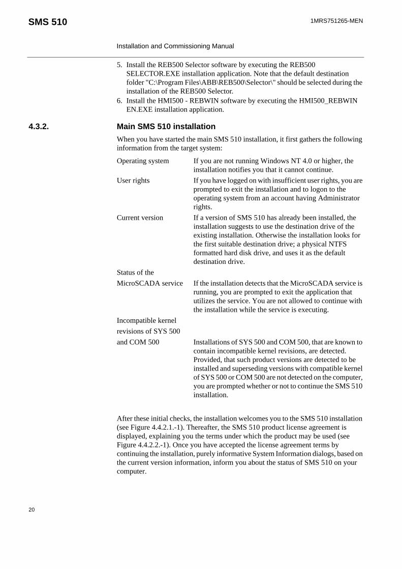
4.3.2. Main SMS 510 installationWhen you have started the main SMS 510 installation, it first gathers the following information from the target system:
Operating system If you are not running Windows NT 4.0 or higher, the installation notifies you that it cannot continue.
User rights If you have logged on with insufficient user rights, you are prompted to exit the installation and to logon to the operating system from an account having Administrator rights.
Current version If a version of SMS 510 has already been installed, the installation suggests to use the destination drive of the existing installation. Otherwise the installation looks for the first suitable destination drive; a physical NTFS formatted hard disk drive, and uses it as the default destination drive.
Status of theMicroSCADA service If the installation detects that the MicroSCADA service is
running, you are prompted to exit the application that utilizes the service. You are not allowed to continue with the installation while the service is executing.
Incompatible kernelrevisions of SYS 500and COM 500 Installations of SYS 500 and COM 500, that are known to
contain incompatible kernel revisions, are detected. Provided, that such product versions are detected to be installed and superseding versions with compatible kernel of SYS 500 or COM 500 are not detected on the computer, you are prompted whether or not to continue the SMS 510 installation.
After these initial checks, the installation welcomes you to the SMS 510 installation (see Figure 4.4.2.1.-1). Thereafter, the SMS 510 product license agreement is displayed, explaining you the terms under which the product may be used (see Figure 4.4.2.2.-1). Once you have accepted the license agreement terms by continuing the installation, purely informative System Information dialogs, based on the current version information, inform you about the status of SMS 510 on your computer.
20

1MRS751265-MEN SMS 510 Installation and Commissioning Manual
Next, you enter the Select dialog, which is the main dialog of the installation (see Figure 4.4.2.6.-1). Provided, that the current version is the same one you are installing and you are using the suggested destination drive, you can select any combination of the available installation options. Otherwise, the installation forces to install all the available options to the selected destination drive. You can change the destination drive by means of the Select Destination Drive dialog, which you can access from the Select dialog.
Once you are satisfied with the settings you have specified, you can start the actual software installation from the main dialog. Notice that prior to that, your computer has not been modified in any way.
If you install the Base System, the installation prompts you for the following information:
• Password for the MicroSCADA user account. Whether this MicroSCADA user account information is requested depends on the configuration of your computer.
• The operating system user groups to which you wish to grant the rights to start and stop the MicroSCADA service on your computer.
Finally, when the installation has been completed, you are notified about it. Depending on the status of some of the installed files, you may be requested to reboot your computer.
After the installation has been completed, you will find a program folder named SMS 510 which contains the icons for using the SMS 510 software. In addition, a shortcut to this program folder will also be added onto your operating system desktop.
4.3.3. Installation of other softwareThe installation of Parameter Setting Tool, CAP 2/316, REB500 Selector and HMI500 - REBWIN is done separately from the main installation by means of the related stand-alone installation applications. Note that these tools need not to be installed if REx 5xx, RE. 216/316 or REB500 relay object types are not used within the SMS 510.
Note also that it is possible to install these applications (same or newer versions) from their original installation CDs or any other source, instead of using the versions located in the SMS 510 installation CD. If doing so, the installation must be carried out with caution to proper folders.
4.4. Installing the software
4.4.1. Starting the main installationTo start the SMS 510 installation, place the SMS 510 Program CD into your CD-ROM drive. The installation application is named as SMS510.EXE and it is located in the root directory of the Program CD.
For example, provided, that your CD-ROM drive has been assigned the drive letter 'Y:' do the following steps:
21

1MRS751265-MEN
Installation and Commissioning Manual
SMS 510
• Press the <Control>+<Esc> key combination to open the Start Menu of the operating system.
• Choose 'Run' and enter the following command in the Run dialog box:
Y:\SMS510.EXE
• Click OK to start the SMS 510 installation.
If the initial checks are passed without any notifications, the installation enters the Installation Wizard directly, which is explained in the following.
4.4.2. Installation WizardThe software installation comprises a series of dialogs referred to as the Installation Wizard, which guides you through the SMS 510 installation. The installation can be exited virtually at any point by either clicking Exit where available or by pressing the <Esc> key from the keyboard. You will be prompted to confirm that you actually wish to exit the installation prematurely.
Most of the information needed to install SMS 510 is gathered in the Installation Wizard dialogs. Thereafter, the installation transfers the software onto your computer. However, during the process of transferring the software, you may be prompted for additional information depending on your computer configuration.
The following paragraphs describe in detail each of the Installation Wizard dialogs in the order they appear during the installation.
4.4.2.1. WelcomeThe Welcome dialog welcomes you to the SMS 510 installation (see Figure 4.4.2.1.-1.)
Fig. 4.4.2.1.-1 The Welcome dialog
Click OK to continue with the installation. To exit the installation, click Cancel.
22

1MRS751265-MEN SMS 510 Installation and Commissioning Manual
4.4.2.2. Product License AgreementThe Product License Agreement dialog contains the license agreement of SMS 510 (see Figure 4.4.2.2.-1).
Fig. 4.4.2.2.-1 The Product License Agreement dialog
To accept the terms of the license, click Yes to continue. If you do not accept these terms, click No to exit the installation. This dialog is displayed only once during the installation.
23

1MRS751265-MEN
Installation and Commissioning Manual
SMS 510
4.4.2.3. System Information 1If you have previously not installed SMS 510, you will see the System Information dialog shown in Figure 4.4.2.3.-1.
Fig. 4.4.2.3.-1 The System Information dialog
To display the Select dialog, click Next>>. Otherwise, click Exit to exit the installation.
24

1MRS751265-MEN SMS 510 Installation and Commissioning Manual
4.4.2.4. System Information 2 If the installation detects that a SMS 510 version above 1.0.0 has been installed to the destination, you will see the System Information dialog shown in Figure 4.4.2.4.-1.
Fig. 4.4.2.4.-1 The System Information dialog
The current version information is available here for viewing. To display the Select dialog, click Next>>. Otherwise, click Exit to exit the installation.
25

1MRS751265-MEN
Installation and Commissioning Manual
SMS 510
4.4.2.5. System Information 3 If the installation detects that the same version of SMS 510 has been installed to the destination, you will see the System Information dialog shown in Figure 4.4.2.5.-1.
Fig. 4.4.2.5.-1 The System Information dialog
The current version information is available here for viewing. To display the Select dialog, click Next>>. Otherwise, click Exit to exit the installation.
26

1MRS751265-MEN SMS 510 Installation and Commissioning Manual
4.4.2.6. Select - forced installationIn case of a forced installation, you will see the Select dialog shown in Figure 4.4.2.6.-1.
Fig. 4.4.2.6.-1 The Select dialog
This dialog provides the following information:
• The currently selected destination drive and the root directory under which the software will be installed.
• The amount of hard disk space that is required and available on the currently selected destination drive.
• A notification that you cannot choose individual options.
As stated in this dialog, the options represented in the dialog cannot be selected.
27

1MRS751265-MEN
Installation and Commissioning Manual
SMS 510
To change the destination drive for the installation, click Change Drive (see the description of “The Destination Drive dialog” on page 29). To view the previously displayed System Information dialog, click <<Back. If you are satisfied with the current settings, click Start to start the actual software installation.
4.4.2.7. Select - non-forced installationIn case of a non-forced installation, you will see the Select dialog shown in Figure 4.4.2.7.-1.
Fig. 4.4.2.7.-1 The Select dialog for a reinstallation
This dialog provides the following information:
• The currently selected destination drive and the root directory under which the software will be installed.
• The amount of hard disk space that is required and available on the currently selected destination drive.
• The software options which will be installed.
The selected options have a check mark on their left side and are subject to installation. Clicking with the mouse on an option toggles its selection status.
28

1MRS751265-MEN SMS 510 Installation and Commissioning Manual
To change the destination drive for the installation, click Change Drive to see the description of the Destination Drive dialog below. To view the previously displayed System Information dialog, click <<Back. If you are satisfied with the current settings, click Start to start the actual software installation.
4.4.2.8. Destination DriveThis dialog allows you to select the destination drive for the installation.
Fig. 4.4.2.8.-1 The Destination Drive dialog
All disk drives available to the operating system are listed on the drive list (highlighted in the above figure). In addition, the amount of available and required hard disk space is also shown on the lower right area of the dialog.
Press the <F4> key from the keyboard or click on the arrowhead on the right side of the drive list to view it in the drop-down mode. You can either use the arrow keys on the keyboard or the mouse to select a drive from the list.
29

1MRS751265-MEN
Installation and Commissioning Manual
SMS 510
As you change the selection, the installation checks whether the drive can be used for installing the software. If it cannot be used, you will see a notification message and the drive that was selected at the time of entering the dialog, is reset as the destination drive. The possible notifications are described in more detail in Section “Troubleshooting destination drive error messages” on page 141.
To use the selected drive and to return to the Select dialog, click OK. Otherwise, click Cancel and the changes to the destination drive will be discarded as you return to the Select dialog.
4.4.2.9. InstallingOnce you have clicked the Start button on the Select dialog, the progress of the installation is displayed in a dialog shown in Figure 4.4.2.9.-1.
Fig. 4.4.2.9.-1 The Installing dialog
You may cancel the installation by clicking Cancel.
MicroSCADA user account
Overview Properly configured MicroSCADA user account on your computer is essential for SMS 510. The account is added/configured on your computer by means of the MicroSCADA User Password dialog, shown in Figure 4.4.2.9.-2.
After the installation of SMS 510, you will find an icon for this tool in the SMS 510 program folder, so you can also later modify the account configuration when necessary. Usage of this tool requires logging on to the operating system with administrator rights.
If other products, which also utilize the MicroSCADA user account, have already been installed on your computer, it is recommended to use the same password that has been used before for the account, if possible.
No support for a roll-back is available, meaning that you cannot revert to the SMS 510 configuration that existed prior to the installation of new SMS 510.
30

1MRS751265-MEN SMS 510 Installation and Commissioning Manual
Configuring the accountThe MicroSCADA User Password dialog is shown below. This is the only tool you need for the account configuration.
Fig. 4.4.2.9.-2 The MicroSCADA User Password dialog
Enter an appropriate password confirming it. Click OK to apply it. The new password will take effect the next time you start SMS 510. All other properties of the MicroSCADA user account are set automatically.
4.4.2.10. MicroSCADA Service Access Manager
OverviewIf you install the Base System, the MicroSCADA Service Access Manager dialog (shown in Figure 4.4.2.10.-1) appears on the screen. The installation does not continue until you have closed this dialog. The installation adds an icon for this tool to the SMS 510 program folder, so you can use it any time after the installation. Usage of this tool requires that you have logged on to the operating system with administrator rights.
PurposeBy using the MicroSCADA Service Access Manager you can define those user-defined user groups whose members are allowed to start and stop the MicroSCADA service, i.e. start and stop SMS 510 on the computer. In addition to the user-defined user groups, the built-in Users group can also be granted these rights.
The note text on the dialog incorrectly states that the MicroSCADA user account is used for accessing non-local printer resources. In SMS 510, you access non-local printer resources in the logged-on user's security context.
31

1MRS751265-MEN
Installation and Commissioning Manual
SMS 510
By default, all users belonging to the operating system’s Administrators group are granted these rights and, therefore, the tool never displays the Administrators group. If the users of SMS 510 on the computer will not be members of the Administrators group, you should use this tool to set up a proper configuration by granting the appropriate user groups the rights to start and stop the MicroSCADA service.
Fig. 4.4.2.10.-1 The MicroSCADA Service Access Manager dialog
Granting the rights to a groupTo grant the rights to start and stop the MicroSCADA service to the appropriate user groups, first highlight the group in the upper list labelled ‘No service start access’ and click Add. In the above figure, the user group named Standard Corporate Users has been granted these rights.
Revoking the rights from a groupTo revoke the rights from a user group, first highlight the group in the lower list labelled ‘Service start access’ and click Remove. In the above figure, the operating system's built-in user group named Users has been revoked these rights.
This is a system-wide configuration which affects also all the other products using the same kernel software. For example, if you have SYS 500 installed on the computer and you grant the rights to a group named Visitors (intended for ordinary visitors) any logged on member of that group is able to start and stop both SMS 510 and SYS 500 on the computer.
32

1MRS751265-MEN SMS 510 Installation and Commissioning Manual
Saving the configurationTo save the configuration, click Close. Confirm that action by clicking OK on the dialog shown in Figure 4.4.2.10.-2.
Fig. 4.4.2.10.-2 Confirm to save the service access configuration
Discarding changes to the configurationTo close the tool without saving the configuration, click Cancel in the MicroSCADA Service Access Manager dialog. Provided that the configuration has been changed, you must confirm the cancellation by clicking OK on the dialog shown in Figure 4.4.2.10.-3. Otherwise, click Cancel to return to the Service Access Manager.
Fig. 4.4.2.10.-3 Confirm to discard the changes to the service access configuration
4.4.2.11. Installation completedAfter the selected software has fully been transferred onto your system, the SMS 510 installation displays the following message to inform you that the installation has been completed.
Fig. 4.4.2.11.-1 Notification that the installation has been completed successfully
Click OK to acknowledge the message.
33

1MRS751265-MEN
Installation and Commissioning Manual
SMS 510
4.4.2.12. System rebootIf some of the installed files were in use at the time of the installation, you are prompted to reboot your computer (see Figure 4.4.2.12.-1).
Fig. 4.4.2.12.-1 Request to reboot the computer
Click OK to reboot your computer immediately. You may reboot later if you wish, by clicking Cancel. However, notice that before starting SMS 510 or installing other software, you must reboot the computer in order for all of the changes to take effect in the system.
4.4.3. Cancelling the installationWhen you are about to cancel the installation, the dialog shown in Figure 4.4.3.-1 appears on the screen.
Fig. 4.4.3.-1 Confirmation to cancel the installation
Click Exit Setup to exit the installation. Otherwise, click Resume to continue the installation normally.
4.5. Installing the Parameter Setting Tool softwareTo install the Parameter Setting Tool, start the PST.EXE and follow the instructions provided on screen.
34
1MRS751265-MEN SMS 510 Installation and Commissioning Manual
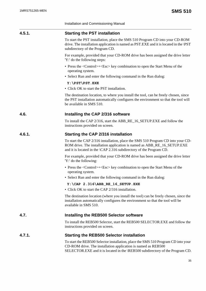
4.5.1. Starting the PST installationTo start the PST installation, place the SMS 510 Program CD into your CD-ROM drive. The installation application is named as PST.EXE and it is located in the \PST subdirectory of the Program CD.
For example, provided that your CD-ROM drive has been assigned the drive letter 'Y:' do the following steps:
• Press the <Control>+<Esc> key combination to open the Start Menu of the operating system.
• Select Run and enter the following command in the Run dialog:
Y:\PST\PST.EXE• Click OK to start the PST installation.
The destination location, to where you install the tool, can be freely chosen, since the PST installation automatically configures the environment so that the tool will be available in SMS 510.
4.6. Installing the CAP 2/316 softwareTo install the CAP 2/316, start the ABB_RE_16_SETUP.EXE and follow the instructions provided on screen.
4.6.1. Starting the CAP 2/316 installationTo start the CAP 2/316 installation, place the SMS 510 Program CD into your CD-ROM drive. The installation application is named as ABB_RE_16_SETUP.EXE and it is located in the \CAP 2.316 subdirectory of the Program CD.
For example, provided that your CD-ROM drive has been assigned the drive letter 'Y:' do the following:
• Press the <Control>+<Esc> key combination to open the Start Menu of the operating system.
• Select Run and enter the following command in the Run dialog:
Y:\CAP 2.316\ABB_RE_16_SETUP.EXE• Click OK to start the CAP 2/316 installation.
The destination location (where you install the tool) can be freely chosen, since the installation automatically configures the environment so that the tool will be available in SMS 510.
4.7. Installing the REB500 Selector softwareTo install the REB500 Selector, start the REB500 SELECTOR.EXE and follow the instructions provided on screen.
4.7.1. Starting the REB500 Selector installationTo start the REB500 Selector installation, place the SMS 510 Program CD into your CD-ROM drive. The installation application is named as REB500 SELECTOR.EXE and it is located in the \REB500 subdirectory of the Program CD.
35

1MRS751265-MEN
Installation and Commissioning Manual
SMS 510
For example, provided that your CD-ROM drive has been assigned the drive letter 'Y:' do the following:
• Press the <Control>+<Esc> key combination to open the Start Menu of the operating system.
• Select Run and enter the following command in the Run dialog:
Y:\REB500\REB500 SELECTOR.EXE• Click OK to start the REB500 Selector installation.
4.8. Installing the HMI500 - REBWIN softwareTo install the HMI500 - REBWIN, start the HMI500_REBWIN EN.EXE and follow the instructions provided on screen.
4.8.1. Starting the HMI500 - REBWIN installationTo start the HMI500 - REBWIN installation, place the SMS 510 Program CD into your CD-ROM drive. The installation application is named as HMI500_REBWIN EN.EXE and it is located in the \REB500 subdirectory of the Program CD.
For example, provided that your CD-ROM drive has been assigned the drive letter 'Y:' do the following:
• Press the <Control>+<Esc> key combination to open the Start Menu of the operating system.
• Select Run and enter the following command in the Run dialog:
Y:\REB500\HMI500_REBWIN EN.EXE• Click OK to start the HMI500 - REBWIN installation.
The destination location (where you install the tool) can be freely chosen, since the installation automatically configures the environment so that the tool will be available in SMS 510.
The default destination folder "C:\Program Files\ABB\REB500\ Selector\" should be selected during the installation of the REB500 Selector. If it cannot be used, then the "ObjType_EXE_Call" keyword value in the "\SMS510\ObjTypes\SM_CH\Reb500\REB500.ini" file must be manually changed after the installation to point to the existing executable:
[REB500]
ObjType_EXE_Call = C:\Program Files\ABB\REB500\ Selector\ selector.exe
36

1MRS751265-MEN SMS 510 Installation and Commissioning Manual
4.9. SMS 510 program folderThe program folder for SMS 510 is named as SMS 510 and it is accessible to all logged on users Figure 4.9.-1. The program folder contains the following subfolders:
1. Doc, containing the SMS 510 manuals.2. Setup, containing additional installation applications.3. Tools, containing both the maintenance and tools that you can also use outside
SMS 510.
Fig. 4.9.-1 SMS 510 program folder
• To start SMS 510, double-click the Start SMS 510 icon.
The three subfolders are explained below.
4.9.1. Subfolder - DocFigure 4.9.1.-1 shows the different manuals in the Doc subfolder.
• To view a manual, double-click the appropriate icon entry. Note! This operation requires that a viewer capable of reading PDF files is installed.
37

1MRS751265-MEN
Installation and Commissioning Manual
SMS 510
Fig. 4.9.1.-1 Subfolder - Doc
4.9.2. Subfolder - Setup Figure 4.9.2.-1 shows the different manuals in the Setup subfolder.
• To install the Adobe Acrobat Reader, close any programs you have running and double-click the Install Adobe Acrobat Reader icon.
• To install the Microsoft Internet Explorer, close any programs you have running and double-click the Install Internet Explorer 4.01 SP2 icon.
• To view the Readme file for Microsoft Internet Explorer installation, double-click the ReadMe icon for Internet Explorer 4.01 SP2.
Fig. 4.9.2.-1 Subfolder - Setup
38

1MRS751265-MEN SMS 510 Installation and Commissioning Manual
4.9.3. Subfolder - Tools • To start the MicroSCADA Service Access Manager tool, double-click the
MicroSCADA Service Access Manager icon.• To start the MicroSCADA User Password tool, double-click the MicroSCADA
User Password icon.• The Notification Window displays messages as they are sent by the system and
tools. All notifications are also stored in the "...\sys\active\sys_\SYS_ERROR.LOG" file. The Notification Window can be used for troubleshooting.
• To start the SPA Terminal Emulator, double-click its icon.
Fig. 4.9.3.-1 Subfolder - Tools
4.9.4. Shortcut to the SMS 510 program folderA shortcut named SMS 510 has been added onto your desktop (see Figure 4.9.4.-1). This shortcut provides access to the SMS 510 program folder from your desktop.
Fig. 4.9.4.-1 The shortcut to the program folder on your desktop
• To open the SMS 510 program folder, double-click the shortcut.
39


1MRS751265-MEN SMS 510 Installation and Commissioning Manual
5. Commissioning
About this chapterThis chapter describes the commissioning activities required after software installation.
5.1. Commissioning tasksCommissioning the installed software involves the following tasks:
• Applying the license information for SMS 510. Whenever the SMS 510 Base System has been installed, this task must be performed. Without proper license information, SMS 510 will not execute. You apply the license information by using the License tool, see Section “Licensing the product - License tool” on page 41.
• Preparing the computer for communication. This comprises the following optional steps:• Installation and configuration of LON communication card(s) and
accompanying device drivers, if not done previously. Those tasks you accomplish by means of the System Configuration tool, see Section “System Configuration Tool” on page 47. Regarding the computer's serial port communication capabilities, it is recommended to verify that the serial ports are correctly configured and working at the operating system level.
• Installation of Remote Access Service (RAS) and modem(s). For detailed instructions, see Section “RAS/Modem installation on Windows NT” on page 84, “RAS/Modem installation on Windows 2000” on page 98 or “RAS/Modem installation on Windows XP” on page 112, depending on the used operating system.
• Ensuring proper Distributed COM (DCOM) identity of the CAP2/316 tool. This is needed to have the CAP2/316 tool to run in the security context of the MicroSCADA user account. For detailed instructions, see Section “CAP2/316 - Distributed COM identity” on page 78.
• Optionally, configuring the operating system's user groups whose members are granted the rights to start and stop the MicroSCADA service on your computer. You grant these rights by using the MicroSCADA Service Access Manager tool. For detailed instructions, see Section “MicroSCADA Service Access Manager” on page 31.
5.2. Licensing the product - License tool
5.2.1. GeneralThe License tool is intended for applying the license information. SMS 510 does not provide any specific entry for accessing this tool. Instead, it appears automatically at SMS 510 start-up, if the computer does not contain a valid license.
41
1MRS751265-MEN
Installation and Commissioning Manual
SMS 510
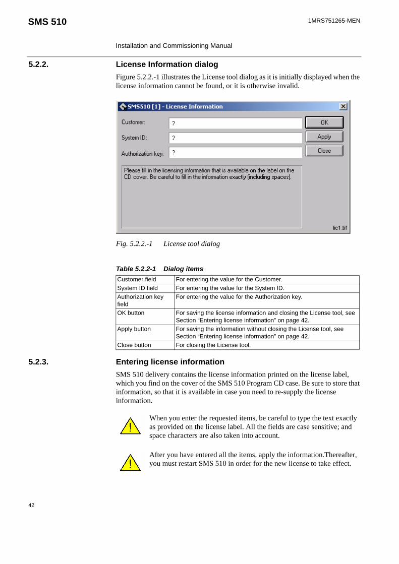
5.2.2. License Information dialogFigure 5.2.2.-1 illustrates the License tool dialog as it is initially displayed when the license information cannot be found, or it is otherwise invalid.
Fig. 5.2.2.-1 License tool dialog
5.2.3. Entering license informationSMS 510 delivery contains the license information printed on the license label, which you find on the cover of the SMS 510 Program CD case. Be sure to store that information, so that it is available in case you need to re-supply the license information.
Table 5.2.2-1 Dialog itemsCustomer field For entering the value for the Customer.System ID field For entering the value for the System ID.Authorization key field
For entering the value for the Authorization key.
OK button For saving the license information and closing the License tool, see Section “Entering license information” on page 42.
Apply button For saving the information without closing the License tool, see Section “Entering license information” on page 42.
Close button For closing the License tool.
When you enter the requested items, be careful to type the text exactly as provided on the license label. All the fields are case sensitive; and space characters are also taken into account.
After you have entered all the items, apply the information.Thereafter, you must restart SMS 510 in order for the new license to take effect.
42

1MRS751265-MEN SMS 510 Installation and Commissioning Manual
To enter the license information:
1. Type the Customer name into the Customer field.2. Type the System ID value into the System ID field.3. Type the Authorization key value into the Authorization key field.4. Click OK or Apply, if you do not want to close the dialog immediately. If the
supplied information is correct, you will see one of the messages shown below:
Fig. 5.2.3.-1 License information added successfully
Fig. 5.2.3.-2 License information updated successfully
5. Dismiss the message by clicking OK. When you close the dialog, you will be further notified with the message shown in Figure 5.2.3.-3.
Fig. 5.2.3.-3 SMS 510 restart required
As stated in the message, you have to restart SMS 510.
43

1MRS751265-MEN
Installation and Commissioning Manual
SMS 510
5.2.4. Invalid license informationIf you have supplied incorrect information, the tool displays the message shown in Figure 5.2.4.-1.
Fig. 5.2.4.-1 Incorrect license information could not be saved
Click OK to dismiss the message and correct the license information carefully.
An example of a correctly entered license information is provided in Figure 5.2.4.-2.
Fig. 5.2.4.-2 An example of license information
5.3. Communication support
5.3.1. Communication protocol supportThe following communication protocols are supported by SMS 510:
• SPA for relay communication• LON for relay communication• TCP/IP for LAN and RAS type of connections
For information on which communication protocols are applicable to various relay terminals, refer to the Tools for Relays and Terminals manual.
44

1MRS751265-MEN SMS 510 Installation and Commissioning Manual
5.3.2. Communication channelsSMS 510 allows you to define the total of eight (8) communication channels in a project's communication configuration. Each defined serial port using SPA protocol and each LON card channel occupies one communication channel. For example, a PCLTA-20 card reserves one communication channel allowing you to define seven serial ports with the SPA protocol.
5.3.3. Serial port communication
5.3.3.1. SMS 510 vs. operating system’s serial port configuration
Serial portsEach serial port defined for use in SMS 510 must also exist at the operating system level. For example, if you define serial ports COM1 through COM4 in SMS 510, you must also define them under the operating system. For detailed information on configuring the serial ports under the operating system, refer to the operating system Help or other applicable source of information.
Advanced serial port settingsAdvanced serial port settings are defined only at the operating system level. Therefore, you do not have to define them in SMS 510. These settings include:
• Interrupt request line (IRQ)• Input/output (I/O) addresses• Data buffering settings
Basic serial port settingsThe basic serial port settings that are defined at the operating system level are overridden by the settings you specify in SMS 510. These settings include:
• Baud rate• Data bits• Parity • Stop bits
5.3.3.2. Using USB portsIn order to utilize a USB port with SMS 510, you need to use a USB to serial adapter. You also need to install the driver software for it (this software is distributed by the adapter). The adapter can be set to a serial port in the range within COM 1 to COM 8. You need to check your operating system setup for a free COM-port.
In the SMS 510 system configuration setting of serial port you select the serial port you have assigned to be provided by the converter. No further settings are required in SMS 510 for using a USB port since the USB looks to a serial adapter like a genuine serial port to SMS 510. USB ports are applicable in Windows 2000 and in Windows XP, not in Windows NT.
45

1MRS751265-MEN
Installation and Commissioning Manual
SMS 510
5.3.4. LON communication
5.3.4.1. LON communication adapters
5.3.4.2. LON communication software components
5.3.5. Time synchronization
5.3.5.1. OverviewAll bay equipment is equipped with a real-time clock for time stamping. When for example a disturbance occurs in a network, the disturbance recorders are trigged, and the time is added to the disturbance record in order to enable post-disturbance analysis. When gathering information from several terminals for analysis, it is of utmost importance that the clocks of different devices are synchronized. SMS 510 provides time synchronization capabilities both over LON and SPA.
5.3.5.2. Time synchronization over LON protocolFor the LON protocol there are two different ways of obtaining the time synchronization functionality. In the first method, the system clock of the SMS 510 workstation is the time source. In the other method, the time source is e.g. a LON Clock Master equipped with a GPS receiver, which is connected to the LON also enabling the synchronization of the system clock of the SMS 510 workstation, if
Table 5.3.4.1-1 LON adapter support
Adapter Type Device driver Remarks
PCLTA-20PCI LonTalk Adapter
PCI half-length bus card
PNPLON SMS 510 supports up to 4 PCLTA-20 cards in the system at the time. Supports Plug-and-Play and downloadable memory.
PCC-10PC Card
A Type II PC card,formerly PCMCIA
PNPLON Only a single card can be present in the system at a time, due to the operating system Type II PC Card support capabilities.Supports Plug-and-Play and downloadable memory.
The PCLTA-10 PC LonTalk Adapter is not supported. RER 109 PCLTA card is also no longer available. It is supported only on Windows NT system.
Table 5.3.4.2-1 Software components for LON communication
Item RemarksMiSCLONPdevice driver
The device driver for the old RER 109 PCLTA Card. Supplied with an installation and a configuration tool (only for Windows NT system).
PNPLONdevice driver
The device driver for the PCC-10 and PCLTA 20 Cards.Supplied as a third party (Echelon) installation and configuration package.
Net Interface Tool For initial configuration of the Neuron Chip(s) on the RER 109 PCLTA Cards.
46

1MRS751265-MEN SMS 510 Installation and Commissioning Manual
desired. Both of these methods can be applied on a SMS 510 workstation simultaneously, provided that there are at least two available LON channels of which one receives the clock sync and the other one sends it.
The used time synchronization is defined separately for every used LON channel. Every single LON channel can have only one time synchronization source. This means that only one device may send the clock sync to the LON bus, and all the other devices read the clock sync from the bus. Any LON channel can also be defined so that it does not participate in the time synchronization function.
The relays connected to the LON bus do not require any settings for the time synchronization; they are preconfigured to receive time synchronization via the LON bus.
5.3.5.3. Time synchronization over SPA protocolFor the SPA protocol, the time synchronization capabilities are reduced so that the system clock of the SMS 510 workstation always acts as the time source, i.e. there is no option to synchronize the SMS 510 workstation's system clock from the SPA. As with LON, any SPA channel can also be defined so that it does not participate in the time synchronization function.
The used time synchronization is defined separately for every used SPA channel. This is a simple On/Off setting which defines whether the time synchronization is sent to a SPA channel or not.
The relays connected to the SPA do not require any settings for the time synchronization; they are synchronized automatically from the SPA channel.
5.3.6. Procedure for commissioning communication componentsGenerally, commissioning the communication components comprises the following tasks:
1. Install the LON communication card(s) into your computer.2. Install the device driver for the LON communication card(s).3. Configure the device driver for the LON communication card(s).4. Configure sufficient amount of serial (COM) ports.
In Windows 2000 and in Windows XP, steps 1 and 2 are done in reverse order. The main tool for accomplishing these tasks is the SMS 510 System Configuration Tool in the following section.
5.4. System Configuration Tool
5.4.1. OverviewThe System Configuration Tool serves the following purposes:
• Creation of the projects' communication configuration which is required to enable communication/time synchronization with the relays. The communication configuration has to be done/verified for every project used in SMS 510. This functionality is available on the Communication page of the System Configuration Tool.
47

1MRS751265-MEN
Installation and Commissioning Manual
SMS 510
• Scheduling of user-defined tasks that are executed automatically without user intervention. This functionality is available on the Scheduler page of the System Configuration Tool.
• Specification of general settings; currently this includes the Autologoff configuration, System Self Supervision and MicroSCADA user password. This functionality is available on the General Settings page of the System Configuration Tool.
5.4.1.1. SchedulerFor detailed information on the Scheduler functionality, refer to the SMS 510 User’s Guide.
5.4.1.2. General SettingsFor detailed information on the general settings, refer to the SMS 510 User’s Guide.
5.4.1.3. Communication configurationEvery project has its own copy of the communication configuration, which is enforced when the project is opened into the Project Structure Navigator. Likewise, when a project is closed, its communication configuration is stored with the project.
The System Configuration Tool automatically edits the communication configuration of the project that is being opened into the Project Structure Navigator. If there is no project open in the Project Structure Navigator, the System Configuration Tool will not execute.
In every project's communication configuration you define:
• Serial ports that are to be used for various types of communication• LON card(s) that are to be used for LON communication• Time synchronization settings for each SPA and LON channel
5.4.2. StartingIn order to access this tool, two entry points are provided:
• System Tools menu in the Project Structure Navigator• The Communication page of the General Object Attributes dialog
5.4.3. System Configuration tool dialog Figure 5.4.3.-1 illustrates the System Configuration Tool dialog.
The Communication page contains two pages:
• Serial Ports• LON
Some of the System Configuration Tool functions, such as modifying LON device driver settings, require administrator rights at the operating system level.
48

1MRS751265-MEN SMS 510 Installation and Commissioning Manual
Fig. 5.4.3.-1 Communication page of the System Configuration Tool dialog
Table 5.4.3-1 System Configuration Tool items
Communication configuration pagesSerial Ports For managing serial port configuration, see Section “Serial Ports
page” on page 50.LON For managing the LON configuration, see Section “LON page” on
page 53.
Common dialog buttonsOK For closing the System Configuration Tool and saving the
configuration, see Section “Save configuration - close tool” on page 58.
Cancel For closing the System Configuration Tool without saving the configuration, see Section “Discard configuration changes” on page 59.
Apply For saving the configuration without closing the System Configuration Tool, see Section “Save configuration - proceed configuration” on page 58.
49

1MRS751265-MEN
Installation and Commissioning Manual
SMS 510
5.4.3.1. Serial Ports pageFigure 5.4.3.1.-1 displays the Serial Ports page of the System Configuration Tool. Initially the configuration is empty, as illustrated.
Fig. 5.4.3.1.-1 The Serial Ports page
Table 5.4.3.1-1 Serial Ports page itemsSerial Ports List for selecting a serial port. Displays all the currently defined
serial ports.Protocol List for assigning the communication protocol to the currently
selected serial port.Connection Type List for selecting the type of the remote connection. Enabled only
when the protocol is SPA.Modem Command (AT)
Field for defining the modem initialization command for remote connections over a modem. Enabled only when connection type is 'Modem'.
Baud Rate List for assigning the baud rate to the currently selected serial port.Data Bits List for assigning the data bits setting to the currently selected serial
port.Parity List for assigning the parity setting to the currently selected serial
port.Stop Bits List for assigning the stop bits setting to the currently selected serial
port.
50

1MRS751265-MEN SMS 510 Installation and Commissioning Manual
5.4.3.2. Serial ports - AddingTo add a serial port:
1. Click Add … to bring up the dialog shown in Figure 5.4.3.2.-1.2. Enter the serial port number, which must be in range of 1 through 8. If you enter
an out-of-range value, or a value which is already in use, you are requested to enter a proper value.
Fig. 5.4.3.2.-1 Define the port number for the new COM port
3. Click OK to add the new serial port, which appears on the Serial Ports list (see Figure 5.4.3.2.-2). Otherwise, click Cancel to keep the configuration unchanged.
Add … button For adding a new serial port, see Section “Serial ports - Adding” on page 51.
Delete … button For deleting the currently selected serial port, see Section “Serial ports - Deleting” on page 53.
Send clock synchronization check box
For configuring whether the relays that are connected to the currently selected serial port are synchronized. Not available for modem connections. Enabled only when the protocol is SPA.
Table 5.4.3.1-1 Serial Ports page items
51

1MRS751265-MEN
Installation and Commissioning Manual
SMS 510
Fig. 5.4.3.2.-2 A new serial port COM1 added with default values
Certain default values are assigned to the newly added port's basic settings and communication protocol. If you wish to use other than the default values, you can configure them as described below.
5.4.3.3. Serial ports - ConfiguringThe following table displays serial port properties, which you can configure on a per-port basis.
To configure a serial port property:
1. Select the serial port from the Serial Ports list.2. Configure the item by selecting the desired value from the appropriate list.
Table 5.4.3.3-1 Configurable serial port properties
Property Available valuesCommunication protocol SPABaud Rate 300, 600, 1200, 2400, 4800, 9600, 19200Data Bits 5, 6, 7, 8Parity None, Odd, EvenStop Bits 1, 2Send clock synchronization On / Off
52

1MRS751265-MEN SMS 510 Installation and Commissioning Manual
5.4.3.4. Serial ports - Deleting Any serial port, defined in a project's system configuration, can be deleted at any time.
To delete a serial port from the configuration:
1. Select the serial port from the Serial ports list.2. Click Delete ….3. When prompted to confirm the deletion (see Figure 5.4.3.4.-1), click Yes to
delete the serial port. Otherwise click No to leave the serial port intact.
Fig. 5.4.3.4.-1 Confirm to delete the selected serial port
The deletion invalidates the communication settings of any device objects which have been configured to use the port you are about delete.
5.4.3.5. LON pageFigure 5.4.3.5.-1 displays the System Configuration Tool's LON page. Initially no card is selected, as illustrated in the figure.
If you accidentally delete ports, you can revert to the most recently saved system configuration by clicking Cancel (see Section “Discard configuration changes” on page 59).
53

1MRS751265-MEN
Installation and Commissioning Manual
SMS 510
Fig. 5.4.3.5.-1 The LON page
5.4.3.6. Selecting the adapterThe System Configuration Tool allows you to use only a single type of a LON card at a time, i.e. you cannot have multiple types of LON cards in-use simultaneously. The LON card is selected from the Adapter type list. If you do not use any LON cards, select the option No card from the list.
Table 5.4.3.5-1 LON page itemsAdapter type List for selecting the adapter type. Displays all the supported
adapters.Card List for assigning the Subnet, Node and time synchronization
settings to the LON channels.Install Driver… button For installing/configuring the driver for the currently selected
adapter.Note! Driver installation and some of the configuration functions require that you have logged on with Administrator Rights.
Configure Channel… button
For configuring the currently selected channel.
Delete Channel...button
For deleting the currently selected channel.
54

1MRS751265-MEN SMS 510 Installation and Commissioning Manual
When you select an adapter from the Adapter type list, the tool scans the computer for currently defined LON devices for the selected adapter type. If such are found, they will be displayed immediately, allowing you to take the channel(s) into use by assigning the appropriate channel settings (see Section “Assigning Subnet/Node settings” on page 55).
If no LON devices have been defined or you want to modify the current configuration e.g. by adding new devices or removing currently defined devices, click the Install Driver button. This invokes the application, which installs the device driver onto your computer.
5.4.3.7. Assigning Subnet/Node settingsEach LON channel needs to have a unique Subnet/Node value pair assigned to it, since it appears as any other node on the network. Valid range is 1 through 127, inclusive for both the Subnet and Node. It is also required to specify the time synchronization setting on a per LON channel basis.
To assign the Subnet/Node values to a LON channel:
1. Click on the intended channel's Subnet cell with the mouse to activate it (see Figure 5.4.3.7.-1).
Fig. 5.4.3.7.-1 Activation of the Subnet cell
2. Type in the appropriate value for the Subnet.
55
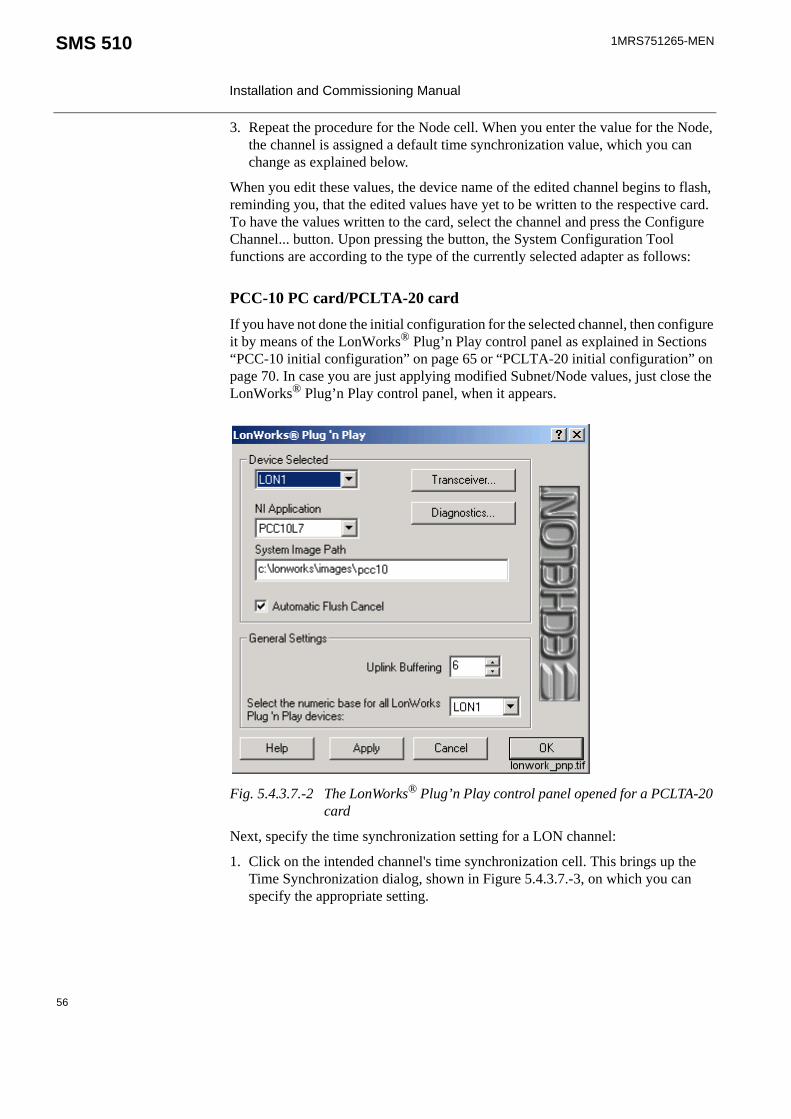
1MRS751265-MEN
Installation and Commissioning Manual
SMS 510
3. Repeat the procedure for the Node cell. When you enter the value for the Node, the channel is assigned a default time synchronization value, which you can change as explained below.
When you edit these values, the device name of the edited channel begins to flash, reminding you, that the edited values have yet to be written to the respective card. To have the values written to the card, select the channel and press the Configure Channel... button. Upon pressing the button, the System Configuration Tool functions are according to the type of the currently selected adapter as follows:
PCC-10 PC card/PCLTA-20 cardIf you have not done the initial configuration for the selected channel, then configure it by means of the LonWorks® Plug’n Play control panel as explained in Sections “PCC-10 initial configuration” on page 65 or “PCLTA-20 initial configuration” on page 70. In case you are just applying modified Subnet/Node values, just close the LonWorks® Plug’n Play control panel, when it appears.
Fig. 5.4.3.7.-2 The LonWorks® Plug’n Play control panel opened for a PCLTA-20 card
Next, specify the time synchronization setting for a LON channel:
1. Click on the intended channel's time synchronization cell. This brings up the Time Synchronization dialog, shown in Figure 5.4.3.7.-3, on which you can specify the appropriate setting.
56

1MRS751265-MEN SMS 510 Installation and Commissioning Manual
Fig. 5.4.3.7.-3 The Time Synchronization dialog
2. Select the setting mode.
Time Synchronization in the Basic modeIf you select the Basic mode, you have the following options:
Time Synchronization in the Advanced mode
If you select the Advanced mode, you have the following options:
Table 5.4.3.7-1 Basic mode
Option ExplanationNo clock synchronization The channel does not participate in time
synchronization.Send synchronization to LON The time sync will be sent to LON via this
channel. This option maps to the 'Link Type 3 - Send LSG and minute pulse' advanced option. This is also the default option when adding new LON channels.
Receive synchronization from LON The system clock of the SMS 510 workstation will be synchronized via this channel. This option maps to the 'Link Type 4 - Receive LSG clock sync' advanced option.Note! Remember that in a project's communication configuration you can have only one LON channel at a time configured with this setting. Otherwise you will be prompted to change the configuration when you attempt to save it.
Table 5.4.3.7-2 Advanced mode
Option ExplanationLink Type 0 - No clock sync The channel does not participate in time
synchronization.Link Type 1 - Send LSG clock sync Send LSG clock sync (for the relays that
utilize nv warning and nv clock telegrams).Link Type 2 - Send minute pulse Send minute pulse (for the relays that utilize
nv time telegram).Link Type 3 - Send LSG and minute pulse Send LSG and minute pulse. Link Type 4 - Receive LSG clock sync Receive LSG clock sync
57

1MRS751265-MEN
Installation and Commissioning Manual
SMS 510
3. Select the appropriate time synchronization setting.4. Click OK.
After you have assigned the appropriate values, save the changes to the communication configuration, as explained below.
5.4.4. Saving system configurationThe system configuration is saved permanently by using either the OK or the Apply button. The difference is that the OK button closes the System Configuration Tool, whereas the Apply button allows you to proceed working with the System Configuration Tool.
The tool also provides you with the possibility to revert to the most recently saved configuration, in order to prevent accidental changes to the configuration (see Section “Discard configuration changes” on page 59).
5.4.4.1. Save configuration - close toolTo save a changed configuration, closing the System Configuration Tool, click OK. The System Configuration Tool prompts you to confirm the operation (see Figure 5.4.4.1.-1).
Fig. 5.4.4.1.-1 Confirm to save the configuration
To save the configuration, click Yes. Clicking No enforces the most recently saved configuration.
5.4.4.2. Save configuration - proceed configurationTo save a changed configuration without closing the System Configuration Tool, click Apply. The System Configuration Tool prompts you to confirm the operation (see Figure 5.4.4.2.-1).
Link Type 5 - Receive minute pulse Receive the minute pulse. Note! It is recommended to use this option only when the other synchronization methods do not work, or when the exact time is not needed because of the inaccuracy on high channel load on a LON line with the minute pulse.
Table 5.4.3.7-2 Advanced mode
Option Explanation
58

1MRS751265-MEN SMS 510 Installation and Commissioning Manual
Fig. 5.4.4.2.-1 Confirm to save the configuration
To save the configuration, click Yes so that the configuration becomes the most recently saved configuration. Otherwise click No to proceed without saving.
5.4.4.3. Discard configuration changesTo revert to the most recently saved configuration, click Cancel. This closes the System Configuration Tool without further notifications.
5.5. Installing LON cards
5.5.1. PCC-10 PC Card commissioning procedureThe communications hardware and software are configured in the following order:
1. Install the card into the PC (see Section “PCC-10 PC Card configuration” on page 63).
2. Install and configure the PCC-10 PC Card device driver (PNPLON), (see Sections “Device driver installation” on page 63 and “PCC-10 initial configuration” on page 65).
5.5.2. PCLTA-20 Card commissioning procedureThe communications hardware and software are configured in the following order:
1. Install the card into the PC (see Section “PCLTA-20 Card configuration” on page 68).
2. Install and configure the PCLTA-20 Card device driver (PNPLON), (see Sections “Device driver installation” on page 68 and “PCLTA-20 initial configuration” on page 70).
5.5.2.1. Installation of the PCLTA-20 adapter to Windows 2000 or Windows XP
Software installationWhen drivers are installed to a Windows 2000 Server where Terminal Services are running, it should be done using the Add/Remove Programs under the Control Panel. Browse the path where the Driver installation file exists. If the operating system is Windows 2000 or Windows XP Professional, you can run the self-extracting installation exe-file directly.
59

1MRS751265-MEN
Installation and Commissioning Manual
SMS 510
1. Launch the PCLTA-20 software installation program. Choose Setup Figure 5.5.2.1.-1.
Fig. 5.5.2.1.-1 Dialog for launching the PCLTA-20 software installation
2. Follow the instructions on the screen (see Figure 5.5.2.1.-2).
Fig. 5.5.2.1.-2 The welcome dialog of the PCLTA-20 Setup program
3. By default, the installation directory is c:\Lonworks. The path may be modified by using the “Browse” button (see Figure 5.5.2.1.-3).
60

1MRS751265-MEN SMS 510 Installation and Commissioning Manual
Fig. 5.5.2.1.-3 The dialog shows the default installation directory
4. At the end of the installation, select the restart option.
PCLTA - 20 Card installation1. Turn off the PC and remove the power cord. 2. Open the PC case and locate an empty 32-bit PCI slot. 3. Check that RER107 LON Communication Adapter is attached to the PCLTA-20
adapter.4. Insert the PCLTA-20 adapter into the slot. 5. Re-insert the power cord and then restart the PC.
A “New Hardware Found” window will be displayed briefly, when the operating system recognizes the PCLTA-20 adapter. You can check if the installation has been successful by using the Control Panel/ Administrative Tool/Computer Management/ Device Manager.
Configuration settings for PCLTA – 20 adapterOpen the Control panel by selecting the “LonWorks Plug’n Play” icon in the Control Panel (see Figure 5.5.2.1.-4 and Table 5.5.2.1-1).
61

1MRS751265-MEN
Installation and Commissioning Manual
SMS 510
Fig. 5.5.2.1.-4 The PCLTA Control Panel
Table 5.5.2.1-1 Description of the PCLTA Control Panel dialog items
Upon clicking the Transceiver... button, Figure 5.5.2.1.-5 will appear on the screen.
Device Selected Controls which PCLTA-20 adapter is selected for configuration.
NI Application Controls the type of image or application to be used. Image should be set to PCC10L7.
Automatic Flush Cancel Should be checked.
Transceiver Opens the PCLTA-20 Transceiver dialog. Settings should be according to Figure 5.5.2.1.-4.
System Image Path Specifies the full directory path for the PCLTA-20 system images. This path is set by the PCLTA-20 Installation software but may be modified by the user.
62

1MRS751265-MEN SMS 510 Installation and Commissioning Manual
Fig. 5.5.2.1.-5 The Transceiver Control Panel
The chosen options have to be according to the ones presented in the dialog. Click the Apply button to enable the driver to utilize the chosen features.
5.5.3. PCC-10 PC Card configuration
5.5.3.1. Device driver installationThe installer for the PCC-10 PC Card device driver is started by clicking the Install Driver… button, located on the LON page of the System Configuration tool (see Figure 5.5.3.1.-1).
63

1MRS751265-MEN
Installation and Commissioning Manual
SMS 510
Fig. 5.5.3.1.-1 Starting the driver installation for the PCC-10 PC Card
Selecting the destination directoryBy default, the destination directory will be C:\LONWORKS. If you decide to install to another directory, you have to manually specify the directory path to the installed system image later.
Selecting the numeric base for LonWorks® devicesDuring the driver installation you is prompted to supply the numeric base for all the LonWorks® Plug’n Play devices. To be compatible with SMS 510, please use 1 as the numeric base, so the device name will be created as LON1.
After the driver installation, restart the computer and perform the initial device driver configuration as explained below.
The program, which you start, installs images and the driver (PNPLON.SYS) for the PCC-10, PCLTA-10 and PCLTA-20 cards.
64

1MRS751265-MEN SMS 510 Installation and Commissioning Manual
5.5.3.2. PCC-10 initial configurationAfter you have installed the PCC-10 card and its device driver, and rebooted the computer, you have to verify that correct settings are to be used. Initialize also the node state of the card’s channel as configured. This means that the following tasks have to be done:
• Select the correct type of transceiver. The default setting FT-10 has to be changed to Custom with appropriate data.
• Select the correct type of the network interface application (NI Application). By default, the device driver installation program configures the NSIPCC as the NI Application. However, NSIPCC has to be changed to PCC10L7.
• Initialize the card to the configured node state, along with the initial Subnet/Node settings.
To configure:
1. Start SMS 510 and enter the LON page of the System Configuration Tool.2. If not selected, select the PCC-10 card as the type of the adapter. By this time, a
LON channel should be available on the System Configuration Tool. If there are none, then the device driver has failed to start and needs to be re-configured. See Section “PCC-10 PC Card preferences” on page 74.
3. Enter values for the Subnet and Node, and press the Configure Channel... button to open the LonWorks® Plug’n Play control panel.
Selecting the network interface application4. First, select the PCC10L7 network interface application, as shown below.
Fig. 5.5.3.2.-1 Selecting the correct NI Application
65

1MRS751265-MEN
Installation and Commissioning Manual
SMS 510
5. Check the Automatic Flush Cancel option as in Figure 5.5.3.2.-1 above.6. Click Apply to apply the selections.
Selecting the type of the transceiver7. Click the Transceiver... button to open the dialog shown below.
Fig. 5.5.3.2.-2 Switching from the default transceiver setting to the Custom transceiver
8. From the Transceiver list, select the Custom option.9. Select Single Ended as the type of the transceiver.10.Set the Bit rate to 1250 Kb.11. For Raw data - Layer 1 timing, ensure that the following data ‘08-05-0C-0E-
0F’ is used.12.For Raw data - Xcvr params, ensure that the following data ‘00-04-00-A4-00-
00-00-00-00’ is used.13.Click OK to save the configuration closing the Transceiver dialog. Next,
initialize the card to the configured state as explained below.
Initializing the node state to be configured
14.On the LonWorks® Plug’n Play control panel (see Figure 5.5.3.2.-1 above), click the Diagnostics... button to open the Diagnostics dialog shown below.
66

1MRS751265-MEN SMS 510 Installation and Commissioning Manual
Fig. 5.5.3.2.-3 Some basic diagnostics information available indicating that the device driver has been started and can be configured
15.Initialize the node state to configured by clicking Reset.16.Verify the initialization by clicking Test. Observe that the Node State is reported
to be Configured as in the figure below.
Fig. 5.5.3.2.-4 Results of the Test function, the state is now configured
17.At this stage the card is ready for use. Click OK to close the dialog. Close also the LonWorks® Plug’n Play control panel by clicking OK on it and continue your work with the System Configuration Tool.
67

1MRS751265-MEN
Installation and Commissioning Manual
SMS 510
For additional information on configuring the PCC-10 device driver, you may want to view the Windows Help shipped with the device driver package. See also Section “PCC-10 PC Card preferences” on page 74.
To access the Help, open the operating system’s Control Panel and open the applet titled LonWorks® Plug’n Play, shown in Figure 5.5.3.2.-5.
Fig. 5.5.3.2.-5 Starting the LonWorks® Plug’n Play applet
Once the LonWorks® Plug’n Play applet is running, click Help to view the Help for the package.
5.5.4. PCLTA-20 Card configuration
5.5.4.1. Device driver installationThe installer for the PCLTA-20 Card device driver is started by clicking the Install Driver… button, located on the LON page of the System Configuration Tool (see Figure 5.5.4.1.-1).
68

1MRS751265-MEN SMS 510 Installation and Commissioning Manual
Fig. 5.5.4.1.-1 Starting the driver installation for the PCLTA-20 Card
Selecting the destination directoryBy default, the destination directory is C:\LONWORKS. If you decide to install to another directory, you have to manually specify the directory path to the installed system image later.
Selecting the numeric base for LonWorks® devicesDuring the driver installation you will be prompted to supply the numeric base for all the LonWorks® Plug’n Play devices. To be compatible with SMS 510, please use 1 as the numeric base, so the first device name will be created as LON1, the second as LON2 and so on.
After the driver installation, close SMS 510 prior to restarting the computer and perform the initial configuration as explained below.
The program, which you start, installs images and the driver (PNPLON.SYS) for the PCC-10, PCLTA-10 and PCLTA-20 cards.
69

1MRS751265-MEN
Installation and Commissioning Manual
SMS 510
5.5.4.2. PCLTA-20 initial configurationAfter you have installed the PCLTA-20 card(s) and its device driver, and rebooted the computer, you have to verify that correct settings are to be used. Configure also the node state of each of the channels as configured. This means that the following tasks have to be done:
• Ensure that the correct type of transceiver is used for each channel.• Ensure that the correct type of the network interface application (NI Application)
is used for each channel.• Initialize the card to the configured node state along with initial Subnet/Node
settings.
To configure:
1. Start SMS 510 and enter the LON page of the System Configuration Tool.2. If not selected, select the PCLTA-20 card as the type of the adapter. By this time,
the System Configuration Tool should have as many LON channels as there are PCLTA-20 cards in computer. If there are not, most probably the operating system has failed to provide the card with sufficient/suitable IRQ and I/O resources. Try to free some resources and reboot the computer.
3. For each LON channel, enter values for the Subnet and Node, and press the Configure Channel... button to open the LonWorks® Plug’n Play control panel.
Selecting the device name4. First, ensure that the selected device matches the device name of the channel
you selected in the System Configuration Tool (see Figure 5.5.4.2.-1 below).
Fig. 5.5.4.2.-1 Device name LON1 is selected both in the System Configuration Tool and in the LonWorks control panel
Selecting the network interface application5. Select the PCC10L7 Application, as shown below.
70

1MRS751265-MEN SMS 510 Installation and Commissioning Manual
Fig. 5.5.4.2.-2 Selecting the correct NI Application
6. Check the Automatic Flush Cancel option as in the figure above.7. Click Apply to apply the selections.
Selecting the type of the transceiver8. Click the Transceiver... button to open the dialog shown below.
71

1MRS751265-MEN
Installation and Commissioning Manual
SMS 510
Fig. 5.5.4.2.-3 Switching from the default transceiver setting to the Custom transceiver
9. From the Transceiver list, select the Custom option.10. Select Single Ended as the type of the transceiver.11. Set the Bit rate to 1250 Kb.12.For Raw data - Layer 1 timing, ensure that the following data ‘01-04-00-00-00’
is used.13.For Raw data - Xcvr params, ensure that the following data ‘00-00-00-04-00-
00-00-00-00’ is used.14.Click OK to save the configuration closing the Transceiver dialog box. Next,
initialize the card to the configured state as explained below.
Initializing the node state to configured15.On the LonWorks® Plug’n Play control panel (see Figure 5.5.4.2.-2 above),
click the Diagnostics... button to open the Diagnostics dialog shown below.
72

1MRS751265-MEN SMS 510 Installation and Commissioning Manual
Fig. 5.5.4.2.-4 Some basic diagnostics information available indicating that the device driver has been started and can be configured
16. Initialize the node state to configured by clicking Reset.17. Verify the initialization by clicking Test. Observe that the Node State is
reported to be Configured as in Figure 5.5.4.2.-5 below.
Fig. 5.5.4.2.-5 Results of the Test function, the state is now configured
18. At this stage the card is ready for use. Click OK to close the dialog. Close also the LonWorks® Plug’n Play control panel by clicking OK on it and continue your work with the System Configuration Tool.
73

1MRS751265-MEN
Installation and Commissioning Manual
SMS 510
For additional information on configuring the PCLTA-20 device driver, you may want to view the Windows Help shipped with the device driver package.
To access Help, open the operating system’s Control Panel and the applet titled LonWorks® Plug’n Play (shown in Figure 5.5.4.2.-6).
Fig. 5.5.4.2.-6 Starting the LonWorks® Plug’n Play applet
5.6. Troubleshooting LON
5.6.1. PCC-10 PC Card preferencesIt may be necessary to configure the preferences of the PCC-10 card’s device driver, if you are unable to configure the card to the configured state. In such a case, open the Preferences page of the LonWorks® Plug’n Play control panel and try another IRQ and/or I/O range setting for the card (see Figure 5.6.1.-1 below). You can modify the current settings by means of the up/down buttons on the dialog (see the cursor in the figure).
74

1MRS751265-MEN SMS 510 Installation and Commissioning Manual
Fig. 5.6.1.-1 PCC-10 preferences
The default IRQ setting is automatic. However, on Windows it may happen that the automatic IRQ assignment results in a non-working configuration even if the assigned IRQ appears to be free for use. You can use e.g. the operating system’s diagnostics application (WINMSD.EXE) to determine the IRQs that are free and try to manually set a new IRQ for the PCC-10 card. In the figure above, IRQ 9 has been set for the card. The new setting will take effect on the next computer reboot.
5.6.2. LON channel configuration failureFigure 5.6.2.-1 shows the error message, which may appear upon pressing the Configure Channel... button in computers having the Lon Network Tool (LNT 505) installed. In this case, dismiss the message by clicking OK. Do the corrective measures explained in Section “Recovering from failure to configure PCLTA Card channels” on page 76 and retry the channel configuration.
75
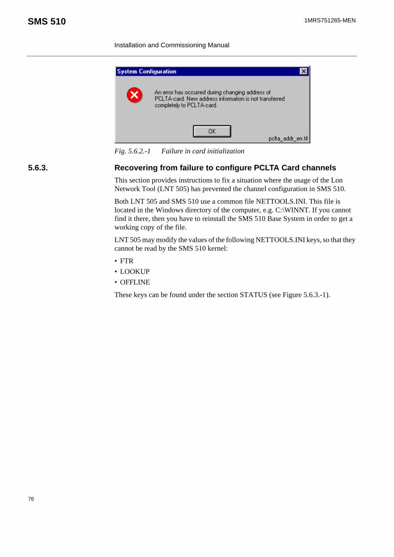
1MRS751265-MEN
Installation and Commissioning Manual
SMS 510
Fig. 5.6.2.-1 Failure in card initialization
5.6.3. Recovering from failure to configure PCLTA Card channelsThis section provides instructions to fix a situation where the usage of the Lon Network Tool (LNT 505) has prevented the channel configuration in SMS 510.
Both LNT 505 and SMS 510 use a common file NETTOOLS.INI. This file is located in the Windows directory of the computer, e.g. C:\WINNT. If you cannot find it there, then you have to reinstall the SMS 510 Base System in order to get a working copy of the file.
LNT 505 may modify the values of the following NETTOOLS.INI keys, so that they cannot be read by the SMS 510 kernel:
• FTR• LOOKUP• OFFLINE
These keys can be found under the section STATUS (see Figure 5.6.3.-1).
76

1MRS751265-MEN SMS 510 Installation and Commissioning Manual
Fig. 5.6.3.-1 An example of the file NETTOOLS.INI. As the selection indicates, lengthy data has been written for the critical keys.
The solution for the problem is to empty the values of the addressed keys, which is a safe operation to do.
To empty the values:
1. Preferably, exit LNT 505 if it is running.
77
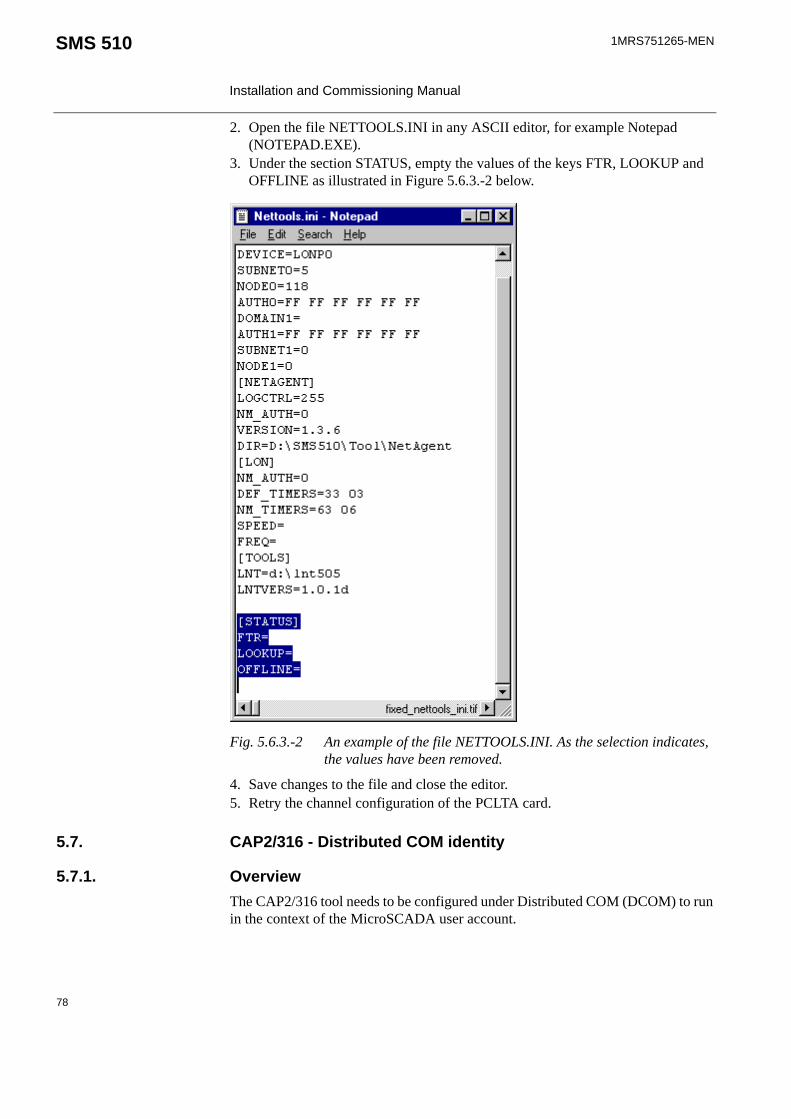
1MRS751265-MEN
Installation and Commissioning Manual
SMS 510
2. Open the file NETTOOLS.INI in any ASCII editor, for example Notepad (NOTEPAD.EXE).
3. Under the section STATUS, empty the values of the keys FTR, LOOKUP and OFFLINE as illustrated in Figure 5.6.3.-2 below.
Fig. 5.6.3.-2 An example of the file NETTOOLS.INI. As the selection indicates, the values have been removed.
4. Save changes to the file and close the editor.5. Retry the channel configuration of the PCLTA card.
5.7. CAP2/316 - Distributed COM identity
5.7.1. OverviewThe CAP2/316 tool needs to be configured under Distributed COM (DCOM) to run in the context of the MicroSCADA user account.
78

1MRS751265-MEN SMS 510 Installation and Commissioning Manual
5.7.2. When to apply the DCOM identityThe DCOM identity has to be configured when:
• You have installed the option REB 500 / RE.x16 Support.• You have changed the password of the MicroSCADA user account on the
computer.• You have renamed a computer, on which this DCOM identity has already been
configured.
5.7.3. DCOM identity configurationThe identity configuration is done by means of the Distributed COM Configuration Properties dialog (DCOMCNFG.EXE), which is part of the operating system installation.
To configure the identity:
1. Choose Run from the operating system’s Start menu.2. Type ‘DCOMCNFG.EXE’ in the Run dialog and click OK. This opens the
Distributed COM Configuration Properties dialog shown in Figure 5.7.3.-1.
Fig. 5.7.3.-1 The list of registered DCOM applications
3. Browse for the application titled ScilComApp, as in the above dialog, and click the Properties… button.
79

1MRS751265-MEN
Installation and Commissioning Manual
SMS 510
4. On the opening dialog, click the Identity tab and select the option This user:.5. As in Figure 5.7.3.-2, type in MicroSCADA as the User. Type in the same
password as is used for the MicroSCADA user account on your computer.
Fig. 5.7.3.-2 MicroSCADA user account as the identity for the application
6. Click OK to return to the previous dialog.7. Click OK to close also the Distributed COM Configuration Properties dialog.
The identity configuration will take effect the next time you start SMS 510.
The following DCOM settings for the ScilComApp object are set by the SMS 510 installation. See Figure 5.7.3.-3 - Figure 5.7.3.-6.
80

1MRS751265-MEN SMS 510 Installation and Commissioning Manual
Fig. 5.7.3.-3 The General page of ScilComApp Properties
81

1MRS751265-MEN
Installation and Commissioning Manual
SMS 510
Fig. 5.7.3.-4 The Location page of ScilComApp Properties
82

1MRS751265-MEN SMS 510 Installation and Commissioning Manual
Fig. 5.7.3.-5 The Security page of ScilComApp Properties
83

1MRS751265-MEN
Installation and Commissioning Manual
SMS 510
Fig. 5.7.3.-6 The Endpoints page of ScilComApp Properties
5.8. RAS/Modem installation on Windows NTThis section describes the installation of Remote Access Service (RAS) and the installation of modem(s) in Windows NT.
5.8.1. OverviewRAS service is not installed automatically in the express installation of Windows NT. It must be installed afterwards, both in the server and in the client computer to enable Remote connections between SMS 510/other systems. The server is configured to accept incoming calls, while the client is configured to make outgoing calls.
The installation procedure comprises the following steps, which will be detailed below:
• Installing modems to both of the involved computers• Installing RAS in both of the involved computers• Installing MS Loopback Adapter driver (in the RAS server computers only)• Configuring start-up of Remote Access Server on the RAS server• Configuring dial-in permissions (in the RAS server computers only)
84

1MRS751265-MEN SMS 510 Installation and Commissioning Manual
• Preparing for dial-up from the client computer
5.8.2. Installing modemsTo install a modem:
1. Double-click the icons My Computer and Control Panel. From Control Panel double-click the Modems icon to bring up the Install New Modem Wizard (see Figure 5.8.2.-1).
Fig. 5.8.2.-1 Installing a new modem in Windows NT
2. You can either use automatic modem detection or enter the RAS communication media manually.
• If you use automatic modem detection, select Next> and follow the instructions on the screen.
• In case you do not wish to use automatic modem detection, the following dialogs will be shown (see Figure 5.8.2.-2 and Figure 5.8.2.-3). Select the type of modem.
85

1MRS751265-MEN
Installation and Commissioning Manual
SMS 510
Fig. 5.8.2.-2 Selecting the modem manually in Windows NT
The installation program searches for the type of the connected modem in the MODEM.INF file, in the directory \WINNT\SYSTEM32\RAS. An error message will be produced, if the modem type is not found.
Check that the modem types you are using are mentioned in the MODEM.INF file. If not, add the required code to the file. The code might be provided on a diskette delivered with the modem.
3. Click Next> to select the serial ports for the modem.
86

1MRS751265-MEN SMS 510 Installation and Commissioning Manual
Fig. 5.8.2.-3 Selecting the communication port manually in Windows NT
4. The modem installation completes with the following dialog (see Figure 5.8.2.-4). To finish the installation, click Finish>.
Fig. 5.8.2.-4 Modem installation is ready in Windows NT
87

1MRS751265-MEN
Installation and Commissioning Manual
SMS 510
5.8.3. Installing Remote Access ServiceRAS must be installed both in the client and server computers. A step-by-step description of the RAS installation is shown below. The configuration differences between the server and the client computers are pointed out. Refer also to the applicable operating system documentation, if necessary.
1. Double-click the icons My Computer and Control Panel. Double-click the Network icon from the Control Panel to bring up the Network tool.
2. Select the Services page and click Add to open up the Select Network Service dialog (see Figure 5.8.3.-1).
Fig. 5.8.3.-1 The list of network services
3. Select Remote Access Service and click OK.4. Select the installation media, e.g. E:\Setups\I386\ (see Figure 5.8.3.-2 below).
Fig. 5.8.3.-2 Selecting the installation media. Here RAS will be installed from a directory on a local hard disk drive
88
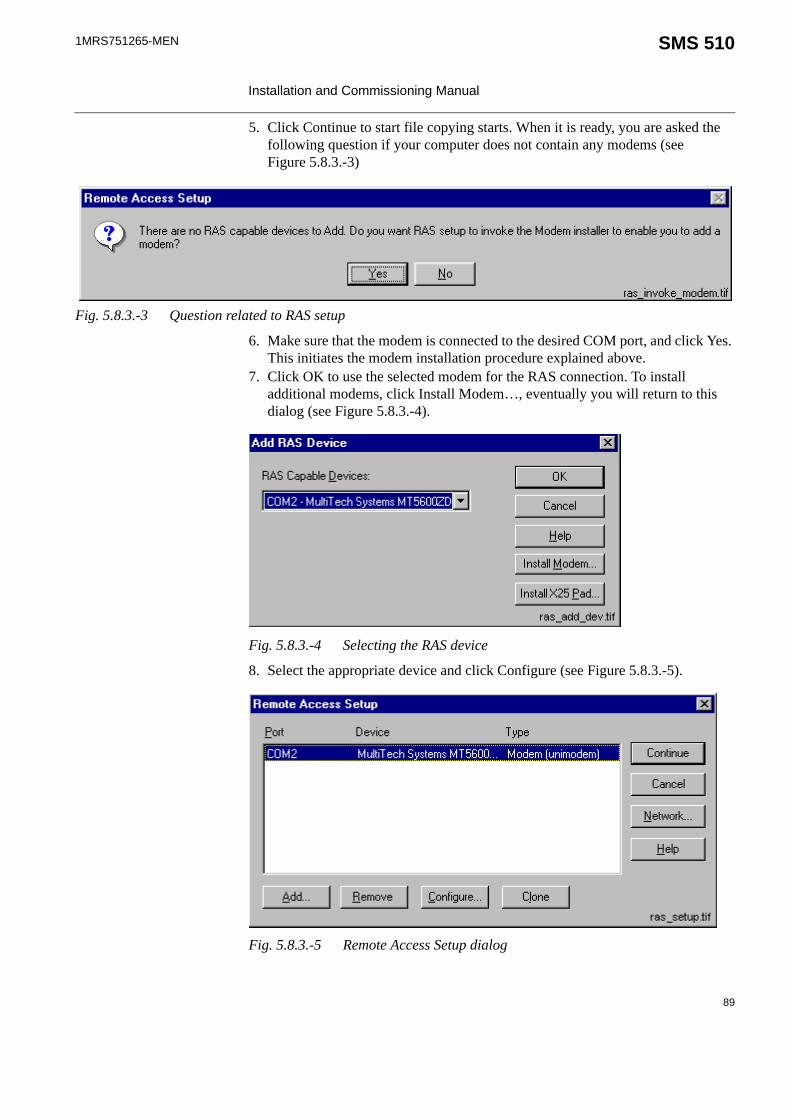
1MRS751265-MEN SMS 510 Installation and Commissioning Manual
5. Click Continue to start file copying starts. When it is ready, you are asked the following question if your computer does not contain any modems (see Figure 5.8.3.-3)
Fig. 5.8.3.-3 Question related to RAS setup
6. Make sure that the modem is connected to the desired COM port, and click Yes. This initiates the modem installation procedure explained above.
7. Click OK to use the selected modem for the RAS connection. To install additional modems, click Install Modem…, eventually you will return to this dialog (see Figure 5.8.3.-4).
Fig. 5.8.3.-4 Selecting the RAS device
8. Select the appropriate device and click Configure (see Figure 5.8.3.-5).
Fig. 5.8.3.-5 Remote Access Setup dialog
89

1MRS751265-MEN
Installation and Commissioning Manual
SMS 510
9. Be sure to select the option Dial out and Receive calls in the server computer Note! The Receive calls option only will not work properly on the server computer. Select Dial out only in the client computer and click OK (see Figure 5.8.3.-6).
Fig. 5.8.3.-6 Configuring Port Usage
10.Click Network (see Figure 5.8.3.-5).11.Select the TCP/IP protocol and click Configure (see Figure 5.8.3.-7).
Fig. 5.8.3.-7 Network Configuration dialog
90

1MRS751265-MEN SMS 510 Installation and Commissioning Manual
Fig. 5.8.3.-8 Entering TCP/IP addresses in the server computer
12.Configure as shown in Figure 5.8.3.-8. Define a range of at least two IP addresses; RAS assigns one IP for both ends of the RAS connection. Do not include the IP for the Loopback adapter in this range.
13.Click OK and Continue.14.If you are operating on a computer which will act as a RAS server, install the
MS Loopback Adapter driver (see the instructions below). Otherwise, you can exit the Network control panel application and restart the computer for the new configuration to take effect.
5.8.4. Installing MS Loopback Adapter driverOn the RAS server computers, installation of MS Loopback Adapter driver is required. This driver is a part of the operating system delivery.
To install the driver:
1. Double-click the icons My Computer and Control Panel. Double-click the Network icon from the Control Panel to bring up the Network tool.
2. Select the Adapters page and click Add to open up the Select Network Adapter dialog (see Figure 5.8.4.-1). Select the MS Loopback Adapter from the list.
91

1MRS751265-MEN
Installation and Commissioning Manual
SMS 510
Fig. 5.8.4.-1 MS Loopback Adapter driver selected
3. Click OK. On the following dialog, accept the default value '802.3' by clicking OK (see Figure 5.8.4.-2).
Fig. 5.8.4.-2 Specifying the frame type for the driver
4. Next, specify the location of your operating system distribution files on the opening dialog (see Figure 5.8.4.-3).
Fig. 5.8.4.-3 Specify the location of the operating system distribution files
92

1MRS751265-MEN SMS 510 Installation and Commissioning Manual
5. Click Continue to install the software. Upon completion, you will return to the Network dialog. Make note that the MS Loopback Adapter has appeared to the list of installed adapters.
6. Next, switch to the Protocols page, select TCP/IP Protocol as in Figure 5.8.4.-4.
Fig. 5.8.4.-4 Selecting the TCP/IP protocol
7. To specify the TCP/IP address for the MS Loopback Adapter, click Properties and select MS Loopback Adapter on the opening dialog as shown in Figure 5.8.4.-5.
93

1MRS751265-MEN
Installation and Commissioning Manual
SMS 510
Fig. 5.8.4.-5 Ready to specify the adapter's IP address
8. Set the IP Address to ‘192.168.0.1’ (see the note below for details) and the Subnet Mask to ’255.255.255.0’. The Default Gateway can be left empty.
9. Click OK and close the Network dialog by clicking Close to finish the installation. The binding information will be updated, when the dialog box closes. The settings will take effect the next time you start the computer.
5.8.5. Considerations when specifying IP addressesIf you want a fast and trouble free installation, follow the above examples to the letter (the above described settings are from a working configuration and can be applied as such).
The IP addresses used in this manual are examples (they are part of reserved IP-ranges or nets that are reserved for private use). It is thus safe to use them anywhere, provided that the same IP addresses are not used for other purposes in the local network. Discuss with someone knowledgeable in TCP/IP networking, if you are not familiar with it yourself. It may/will save you much grief and frustration.
For more information on private nets, please refer to RFC19181.
1. Request For Comments 1918, a document available on Internet. Discusses best current practises in address allocation for private internets.
94

1MRS751265-MEN SMS 510 Installation and Commissioning Manual
5.8.6. Configuring start-up of Remote Access Server serviceIn a RAS server computer, the Remote Access Server service should be configured to start up automatically when the operating system starts. Otherwise, this service has to be manually started to enable RAS client computers to dial-in the server computer.
To configure:
1. Double-click the icon My Computer and Control Panel. Double-click the Services icon from the Control panel.
2. Select Remote Access Server and click Startup (see Figure 5.8.6.-1). This procedure opens the next dialog (see Figure 5.8.6.-2).
Fig. 5.8.6.-1 The Windows NT window for managing services
When configured to start-up automatically, RAS server reserves all the COM port(s) that have been configured to accept incoming calls. This must be kept in mind, when configuring the serial port communications of SMS 510 projects to avoid overlapping COM port usage in RAS and SMS 510. If overlapping settings have been specified, when turned on, SMS 510 System Self Supervision will indicate the COM port(s) that are inaccessible.
95

1MRS751265-MEN
Installation and Commissioning Manual
SMS 510
Fig. 5.8.6.-2 Selecting automatic startup
3. Select Automatic startup.4. Click OK.
5.8.7. Verifying Remote Access Server serviceThe operating system provides the Remote Access Admin tool (RASADMIN.EXE), which can be useful in diagnosing the RAS installation and the connections. Under Windows NT 4.0, this tool is started from the 'Start Menu/Programs/Administrative Tools' menu.
Fig. 5.8.7.-1 Viewing the status of the Remote Access Server service on a server computer
For more information, please refer to the Help shipped with the tool.
5.8.8. Configuring dial-in permissions in the RAS server computerThe RAS client computer dials the server in the security context of the MicroSCADA user account. This means that the account must be granted the permissions to dial-in the RAS server computer.
To grant the permissions:
96
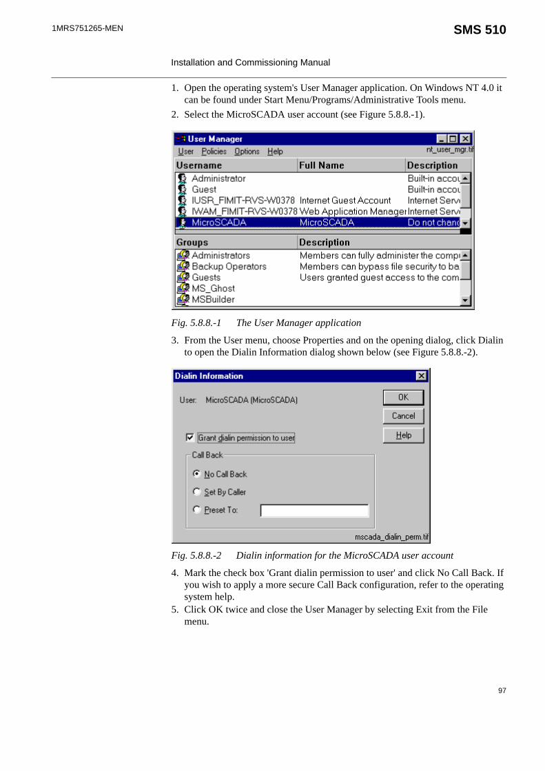
1MRS751265-MEN SMS 510 Installation and Commissioning Manual
1. Open the operating system's User Manager application. On Windows NT 4.0 it can be found under Start Menu/Programs/Administrative Tools menu.
2. Select the MicroSCADA user account (see Figure 5.8.8.-1).
Fig. 5.8.8.-1 The User Manager application
3. From the User menu, choose Properties and on the opening dialog, click Dialin to open the Dialin Information dialog shown below (see Figure 5.8.8.-2).
Fig. 5.8.8.-2 Dialin information for the MicroSCADA user account
4. Mark the check box 'Grant dialin permission to user' and click No Call Back. If you wish to apply a more secure Call Back configuration, refer to the operating system help.
5. Click OK twice and close the User Manager by selecting Exit from the File menu.
97

1MRS751265-MEN
Installation and Commissioning Manual
SMS 510
5.9. RAS/Modem installation on Windows 2000The server is configured to accept incoming calls, while the client is configured to make outgoing calls.
Overview:The installation procedure comprises the following steps:
• Installing modems to both of the involved computers• Creating an incoming connection to server computers• Installing MS Loopback Adapter driver in server computer• Preparing for dial-up from the client computer• Configuring MS Loopback Adapter
To install a modem on Windows 2000:1. Open the Phone and Modem Control in the Control Panel. 2. (Optional) If you are prompted for location information, enter the dialing
information for your location and click OK. 3. On the Modems tab, click Add (see Figure 5.9.-1).4. Follow the instructions in the Install New Modem Wizard.
98

1MRS751265-MEN SMS 510 Installation and Commissioning Manual
Fig. 5.9.-1 Installing a new modem in Windows 2000
5. You can either use automatic modem detection or enter the incoming communication media manually.
• If you use automatic modem detection, select Next> and follow the instructions on the screen.
• In case you do not wish to use automatic modem detection, the following dialogs will be shown (see Figure 5.9.-2 and Figure 5.9.-3). Select the type of modem.
99

1MRS751265-MEN
Installation and Commissioning Manual
SMS 510
Fig. 5.9.-2 Selecting the modem manually in Windows 2000
The installation program searches for the type of the connected modem in the MODEM.INF file. An error message will be produced, if the modem type is not found.
Check that the modem types you are using are mentioned in the MODEM.INF file. If not, add the required code to the file. The code might be provided on a diskette delivered with the modem.
6. Click Next> to select the serial ports for the modem.
100

1MRS751265-MEN SMS 510 Installation and Commissioning Manual
Fig. 5.9.-3 Selecting the communication port manually in Windows 2000
7. The modem installation completes with the following dialog (see Figure 5.9.-4). To end the installation, click Finish>.
101

1MRS751265-MEN
Installation and Commissioning Manual
SMS 510
Fig. 5.9.-4 Modem installation is ready in Windows 2000
Incoming connections:By creating an incoming connection, a computer running Windows 2000 Professional or stand-alone Windows 2000 Server can act as a remote access server.
To make an incoming network connection:
1. Open the Control Panel and choose Network and Dial-Up Connections (see Figure 5.9.-5).
2. Double-click Make New Connection and click Next (see Figure 5.9.-6). 3. Click Accept incoming connections and click Next. Then follow the instructions
in the Network Connection Wizard. The following dialogs will be shown (see Figure 5.9.-7 - Figure 5.9.-11).
102

1MRS751265-MEN SMS 510 Installation and Commissioning Manual
Fig. 5.9.-5 The Control Panel in Windows 2000
Fig. 5.9.-6 Choosing the network connection type in Windows 2000
103

1MRS751265-MEN
Installation and Commissioning Manual
SMS 510
Fig. 5.9.-7 Choosing devices for incoming connections in Windows 2000
Fig. 5.9.-8 Allowing virtual private connections in Windows 2000
104

1MRS751265-MEN SMS 510 Installation and Commissioning Manual
Fig. 5.9.-9 Specifying allowed users to be connected to your computer
Fig. 5.9.-10 Selecting networking components
105

1MRS751265-MEN
Installation and Commissioning Manual
SMS 510
Fig. 5.9.-11 Specifying incoming TCP/IP properties
To install the Microsoft Loopback Adapter in Microsoft Windows 2000:1. Open the Control Panel, choose Add/Remove Hardware, and then choose Next. 2. Choose Add/Troubleshoot a device, and then choose Next. 3. From the Devices list, select Add a new device, and then choose Next (see
Figure 5.9.-12). 4. Choose “No, I want to select the hardware from a list”, and then choose Next. 5. From the Hardware types list, select Network adapters, and then choose Next
(see Figure 5.9.-13).6. From the Manufacturers list, select Microsoft. 7. From the Network Adapter list, select Microsoft Loopback Adapter, and then
choose Next (see Figure 5.9.-14).8. Choose Next, and then choose Finish.
106

1MRS751265-MEN SMS 510 Installation and Commissioning Manual
Fig. 5.9.-12 Adding a new hardware device
Fig. 5.9.-13 Selecting network adapters to be installed
107

1MRS751265-MEN
Installation and Commissioning Manual
SMS 510
Fig. 5.9.-14 Microsoft Loopback Adapter selected to be installed
Preparing dial-up from the client:• To open Network and Dial-up Connections, click Start and point to Settings.Then
click Network and Dial-up Connections. • Double-click Make New Connection, and then click Next. • Click Dial-up to private network and click Next. Then follow the instructions in
the Network Connection wizard.
Configuring Loopback Adapter in Windows 20001. Select the Control Panel and choose Network and Dial-up Connections (see
Figure 5.9.-15).2. Choose Local Area Connection, Microsoft Loopback Adapter (see Figure 5.9.-
16).
108

1MRS751265-MEN SMS 510 Installation and Commissioning Manual
Fig. 5.9.-15 Selecting Network and Dial-up Connections in Windows 2000
Fig. 5.9.-16 Starting to configure Loopback Adapter in Windows 2000
3. Click the right mouse button and choose Properties. Then choose Internet Protocol (TCP/IP) and click the Properties button (see Figure 5.9.-17).
109

1MRS751265-MEN
Installation and Commissioning Manual
SMS 510
Fig. 5.9.-17 Opening the TCP/IP properties in Windows 2000
4. Choose “Use the following IP address” (see Figure 5.9.-18). Set the IP Address to ‘192.168.0.1’ (see Section 5.9.1. for details) and the Subnet Mask to ’255.255.255.0’. The Default Gateway can be left empty. Click OK.
110

1MRS751265-MEN SMS 510 Installation and Commissioning Manual
Fig. 5.9.-18 Configuring the TCP/IP Properties in Windows 2000
5.9.1. Considerations when specifying IP addresses in Windows 2000If you want a fast and trouble free installation, follow the above examples to the letter (the above described settings are from a working configuration and can be applied as such).
The IP addresses used in this manual are examples (they are part of reserved IP-ranges or nets that are reserved for private use). It is thus safe to use them anywhere, provided that the same IP addresses are not used for other purposes in the local network. Discuss with someone knowledgeable in TCP/IP networking, if you are not familiar with it yourself. It may/will save you much grief and frustration.
For more information on private nets, please refer to RFC19181.
1. Request For Comments 1918, a document available on Internet. Discusses best current practises in address allocation for private internets.
111

1MRS751265-MEN
Installation and Commissioning Manual
SMS 510
5.10. RAS/Modem installation on Windows XP
The server is configured to accept incoming calls, while the client is configured to make outgoing calls.
Overview:The installation procedure comprises the following steps:
• Installing modems to both of the involved computers• Creating an incoming connection to server computers• Installing MS Loopback Adapter driver in server computer• Preparing for dial-up from the client computer• Configuring MS Loopback Adapter
To install a modem on Windows XP:1. Open the Phone and Modem Options in the Control Panel. 2. (Optional) If you are prompted for location information, enter the dialing
information for your location and click OK. 3. On the Modems tab, click Add (see Figure 5.10.-1).4. Follow the instructions in the Install New Modem Wizard (see Figure 5.10.-2).
It is very important that the following is taken care of. Otherwise the RAS connection will not work.
In the Network Connections, the Windows Firewall in the Advanced page must be turned off (by default it is on, which prevents any incoming connection to the XP-computer).
Make sure that the following steps for Security settings are carried out:
1. Start the Control panel. 2. Choose Administrative Tools and Local Security Policy settings.3. Choose Local Policies and the Security Options. Set the value of the
option "Network access: Sharing and security model for local accounts" to "Classic - local users authenticate as themselves."
To do this, click the right mouse button and choose Properties. Open the Local Security Settings page and choose "Classic - local users authenticate as themselves."
(By default this option is set to "...local users authenticate as Guest", which leads to "access denied" errors).
112
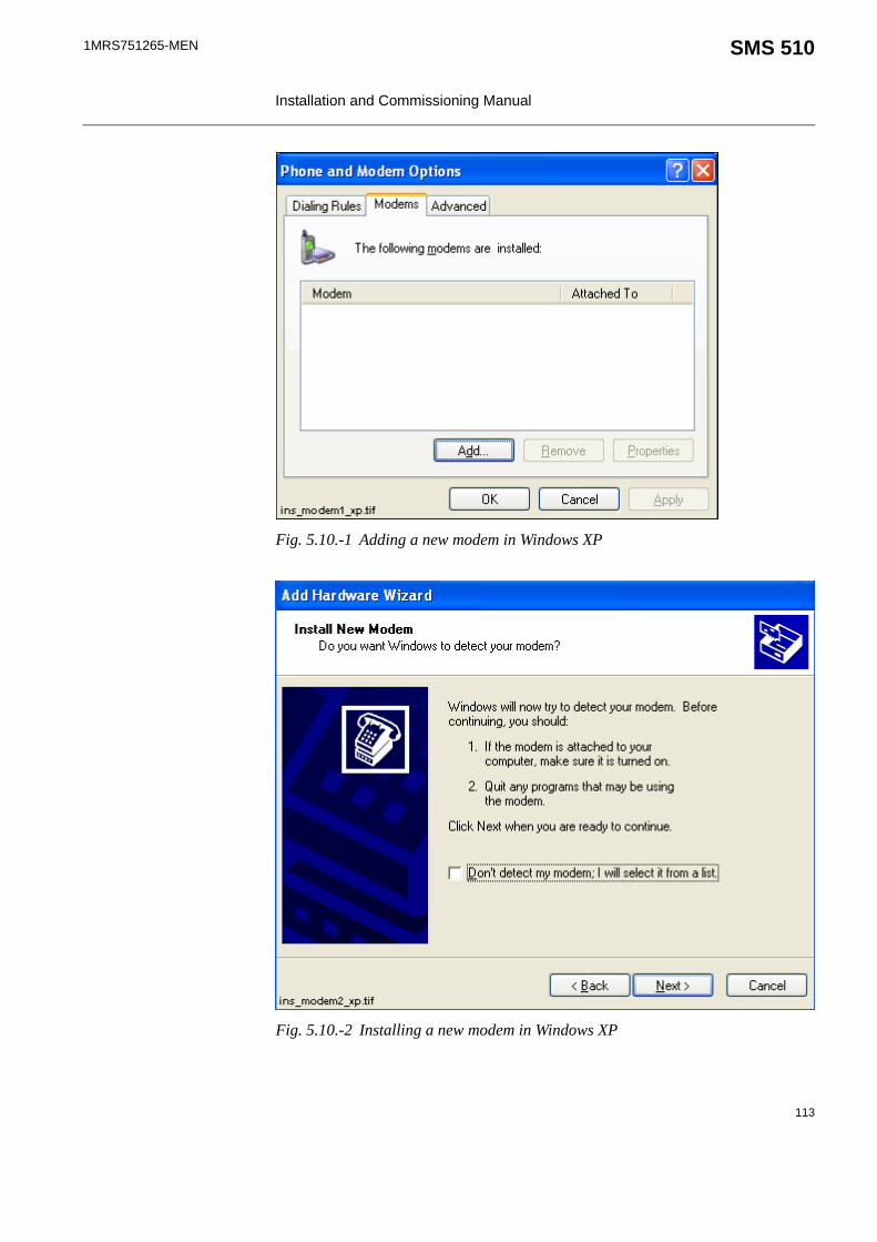
1MRS751265-MEN SMS 510 Installation and Commissioning Manual
Fig. 5.10.-1 Adding a new modem in Windows XP
Fig. 5.10.-2 Installing a new modem in Windows XP
113

1MRS751265-MEN
Installation and Commissioning Manual
SMS 510
5. You can either use automatic modem detection or enter the incoming communication media manually.
If you use automatic modem detection, select Next> and follow the instructions on the screen.
In case you do not wish to use automatic modem detection, check the box “Don’t detect my modem; I will select it from a list.” The following dialogs will be shown (see Figure 5.10.-3 and Figure 5.10.-4). Select the type of modem.
Fig. 5.10.-3 Selecting the modem manually in Windows XP
The installation program searches for the type of the connected modem in the MODEM.INF file. An error message will be produced, if the modem type is not found.
Check that the modem types you are using are mentioned in the MODEM.INF file. If not, add the required code to the file. The code might be provided on a diskette delivered with the modem.
6. Click Next> to select the serial ports for the modem.
114

1MRS751265-MEN SMS 510 Installation and Commissioning Manual
Fig. 5.10.-4 Selecting the communication port manually in Windows XP
7. The modem installation completes with the following dialog (see Figure 5.10.-5). To end the installation, click Finish>.
115

1MRS751265-MEN
Installation and Commissioning Manual
SMS 510
Fig. 5.10.-5 Modem installation is ready in Windows XP
Incoming connections:By creating an incoming connection, a computer running Windows XP Professional can act as a remote access server.
To make an incoming network connection:
1. Open the Control Panel and choose Network Connections (see Figure 5.10.-6).2. Double-click New Connection Wizard and click Next (see Figure 5.10.-7). 3. Choose “Set up an advanced connection” and click the Next button (see
Figure 5.10.-8). 4. Choose “Accept incoming connection” and click the Next button (see
Figure 5.10.-9). Then follow the instructions in the New Connection Wizard. The following dialogs will be shown (see Figure 5.10.-10 - Figure 5.10.-14).
116

1MRS751265-MEN SMS 510 Installation and Commissioning Manual
Fig. 5.10.-6 The Control Panel in Windows XP
Fig. 5.10.-7 Opening New Connection Wizard in Windows XP
117
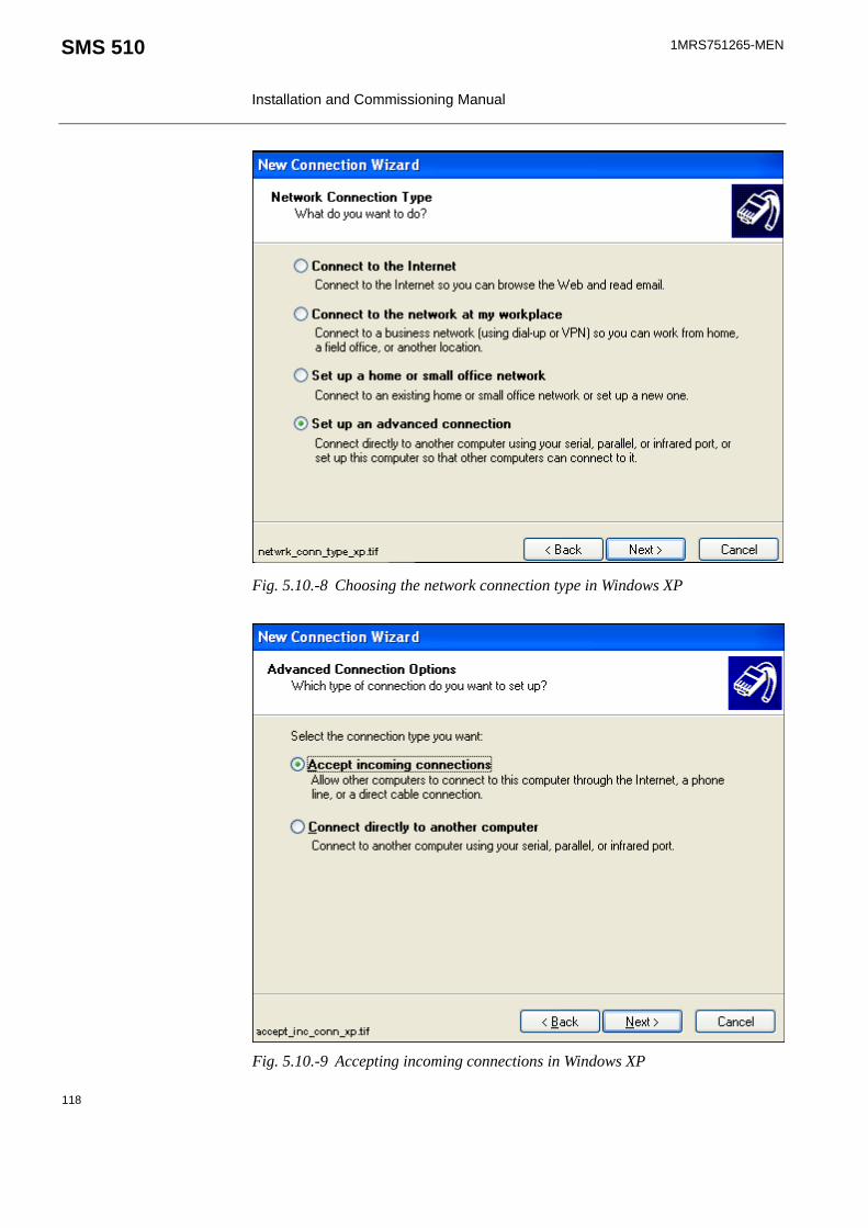
1MRS751265-MEN
Installation and Commissioning Manual
SMS 510
Fig. 5.10.-8 Choosing the network connection type in Windows XP
Fig. 5.10.-9 Accepting incoming connections in Windows XP
118

1MRS751265-MEN SMS 510 Installation and Commissioning Manual
Fig. 5.10.-10 Choosing devices for incoming connections in Windows XP
Fig. 5.10.-11 Allowing virtual private connections in Windows XP
119

1MRS751265-MEN
Installation and Commissioning Manual
SMS 510
Fig. 5.10.-12 Specifying allowed users to be connected to your computer
To configure the TCP/IP properties, click the Properties button (see Figure 5.10.-13).
120

1MRS751265-MEN SMS 510 Installation and Commissioning Manual
Fig. 5.10.-13 Selecting networking components in Windows XP
Fig. 5.10.-14 Specifying incoming TCP/IP properties in Windows XP
121
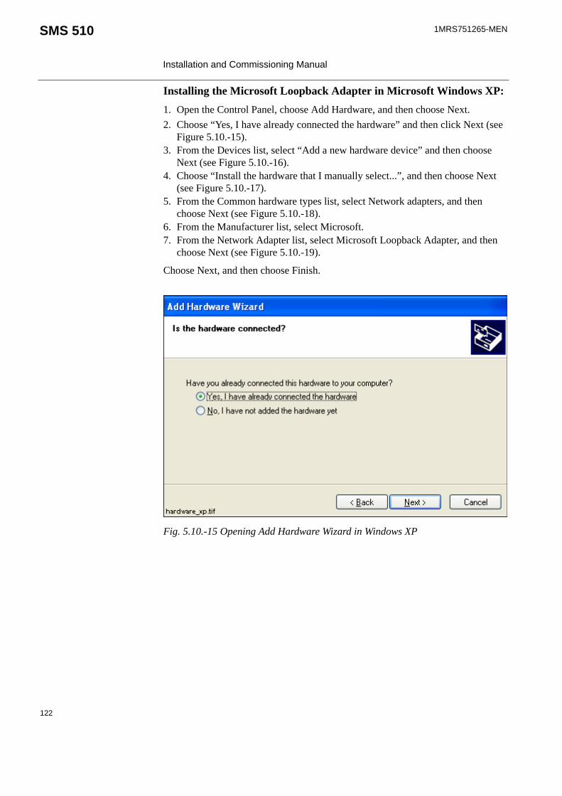
1MRS751265-MEN
Installation and Commissioning Manual
SMS 510
Installing the Microsoft Loopback Adapter in Microsoft Windows XP:1. Open the Control Panel, choose Add Hardware, and then choose Next. 2. Choose “Yes, I have already connected the hardware” and then click Next (see
Figure 5.10.-15). 3. From the Devices list, select “Add a new hardware device” and then choose
Next (see Figure 5.10.-16). 4. Choose “Install the hardware that I manually select...”, and then choose Next
(see Figure 5.10.-17).5. From the Common hardware types list, select Network adapters, and then
choose Next (see Figure 5.10.-18).6. From the Manufacturer list, select Microsoft. 7. From the Network Adapter list, select Microsoft Loopback Adapter, and then
choose Next (see Figure 5.10.-19).
Choose Next, and then choose Finish.
Fig. 5.10.-15 Opening Add Hardware Wizard in Windows XP
122

1MRS751265-MEN SMS 510 Installation and Commissioning Manual
Fig. 5.10.-16 Adding a new hardware device in Windows XP
Fig. 5.10.-17 Selecting the hardware in Windows XP
123

1MRS751265-MEN
Installation and Commissioning Manual
SMS 510
Fig. 5.10.-18 Selecting network adapters to be installed in Windows XP
Fig. 5.10.-19 Microsoft Loopback Adapter selected to be installed
124

1MRS751265-MEN SMS 510 Installation and Commissioning Manual
Configuring Loopback Adapter in Windows XP1. Select the Control Panel and choose Network Connections (see Figure 5.10.-6).2. Choose LAN or High-Speed Internet and Local Area Connection, Microsoft
Loopback Adapter (see Figure 5.10.-20).
Fig. 5.10.-20 Starting to configure the Loopback Adapter in Windows XP
3. Click the right mouse button and choose Properties. Then choose Internet Protocol (TCP/IP) and click the Properties button (see Figure 5.10.-21).
125

1MRS751265-MEN
Installation and Commissioning Manual
SMS 510
Fig. 5.10.-21Opening Internet Protocol (TCP/IP) properties in Windows XP
4. Choose “Use the following IP address” (see Figure 5.10.-22). Set the IP Address to ‘192.168.0.1’ (see Section 5.10.1. for details) and the Subnet Mask to ’255.255.255.0’. The Default Gateway can be left empty. Click OK.
126
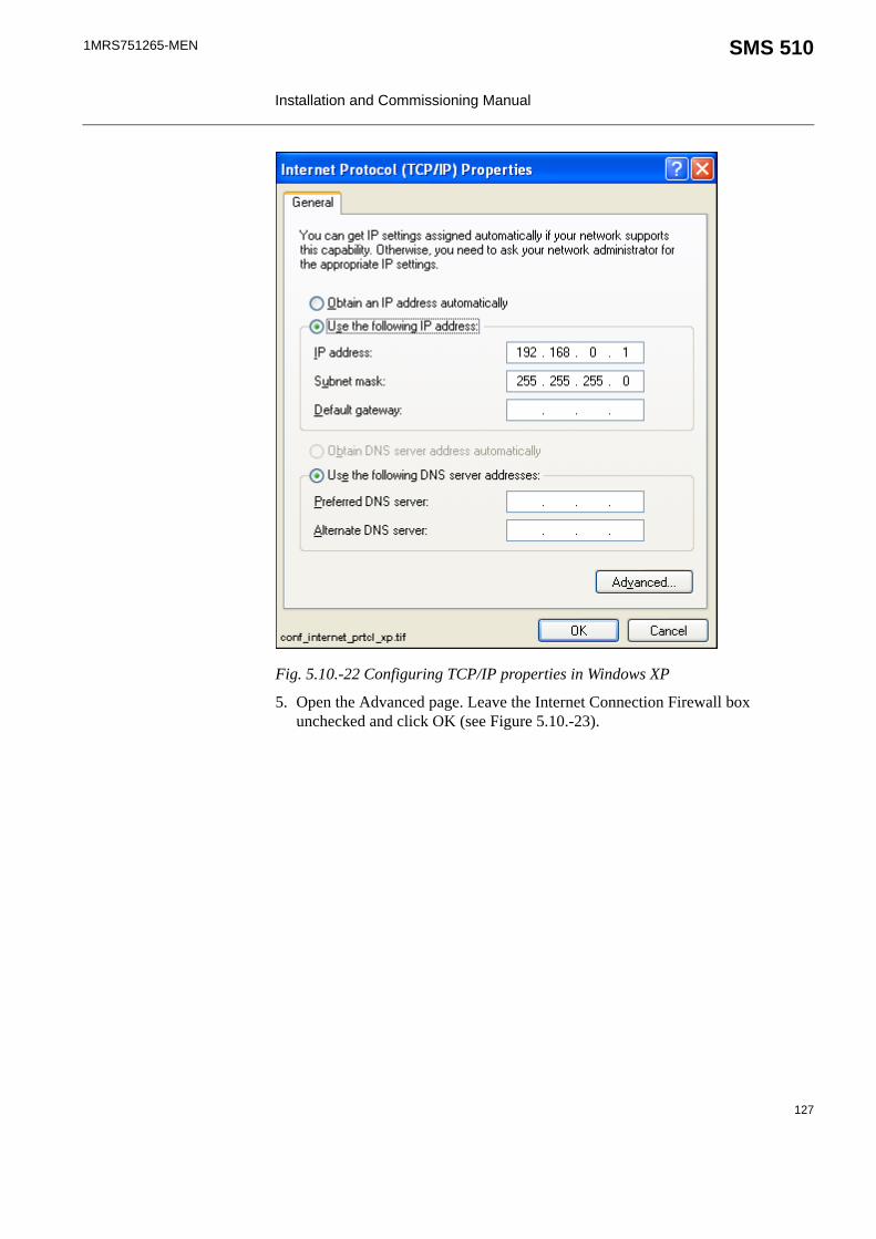
1MRS751265-MEN SMS 510 Installation and Commissioning Manual
Fig. 5.10.-22 Configuring TCP/IP properties in Windows XP
5. Open the Advanced page. Leave the Internet Connection Firewall box unchecked and click OK (see Figure 5.10.-23).
127

1MRS751265-MEN
Installation and Commissioning Manual
SMS 510
Fig. 5.10.-23 Configuring the Advanced TCP/IP options
6. Click OK and close the Network dialog by clicking Close to finish the installation. The settings will take effect the next time you start the computer.
5.10.1. Considerations when specifying IP addresses in Windows XPIf you want a fast and trouble-free installation, follow the above examples to the letter (the above described settings are from a working configuration and can be applied as such).
The IP addresses used in this manual are examples (they are part of reserved IP-ranges or nets that are reserved for private use). It is thus safe to use them anywhere, provided that the same IP addresses are not used for other purposes in the local network. Discuss with someone knowledgeable in TCP/IP networking, if you are not familiar with it yourself. It may/will save you much grief and frustration.
For more information on private nets, please refer to RFC19181.
Local firewalling (in this example, the Internet Connection Firewall) must be turned off. Otherwise the RAS connection will not work.
128

1MRS751265-MEN SMS 510 Installation and Commissioning Manual
5.11. About phonebooks and SMS 510SMS 510 uses a private phonebook, which is not accessible through the operating system's Dial-up Networking functionality. This phonebook is managed by means of the Remote Connection Properties dialog. For more information on utilizing remote connections in SMS 510, see the SMS 510 User’s Guide.
5.12. Dialing-Up in SMS 510In SMS 510 the dial-up takes place when you activate a Remote connection from the Project Structure Navigator. The Project Structure Navigator automatically hangs up the call, when you switch to another connection or open a local project.
5.13. Configuring SMS 510 start-upThis section provides information on how to avoid possible SMS 510 start-up problems that may occur under some operating system configurations. Unless you are experiencing SMS 510 start-up problems, you can skip this section.
5.13.1. Avoiding virtual memory overlap at SMS 510 start-upThe MicroSCADA service of SMS 510 uses a hard-coded address for the address of the memory pool.
However, it is possible that in certain PC configurations, some other system component (e.g. a hardware driver) happens to map on an address within the pool. The MicroSCADA service start-up itself has a search mechanism to handle the address overlapping, but it has no chance to prevent other MicroSCADA processes or external programs from failing to map the memory pool. Consequently, SMS 510 does not start.
If this happens, an error message of the following format will be shown in the SMS 510 error log file \SMS510\SYS\ACTIVE\SYS_\SYS_ERROR.LOG and on the Notification Window (it can be opened from the SMS 510 Tools program folder under Start menu).Add the following line to sys_config.par and restart MicroSCADAMEMORY_POOL_HOLE = 30000000 - 301FFFFF? Map_Global_Memory(MapViewOfFileEx): 487
Since the situation causes SMS 510 (e.g. PICA.EXE program) to crash, the computer must be restarted in order to take the corrective measures explained below.
As the remedy, the MEMORY_POOL_HOLE parameter must be activated in the file \SMS510\SYS\ACTIVE\SYS_\SYS_CONFIG.PAR. This parameter advises the MicroSCADA start-up code not to use the specified virtual memory area for the global memory pool.
1. Request For Comments 1918, a document available on Internet. Discusses best current practises in address allocation for private internets.
129
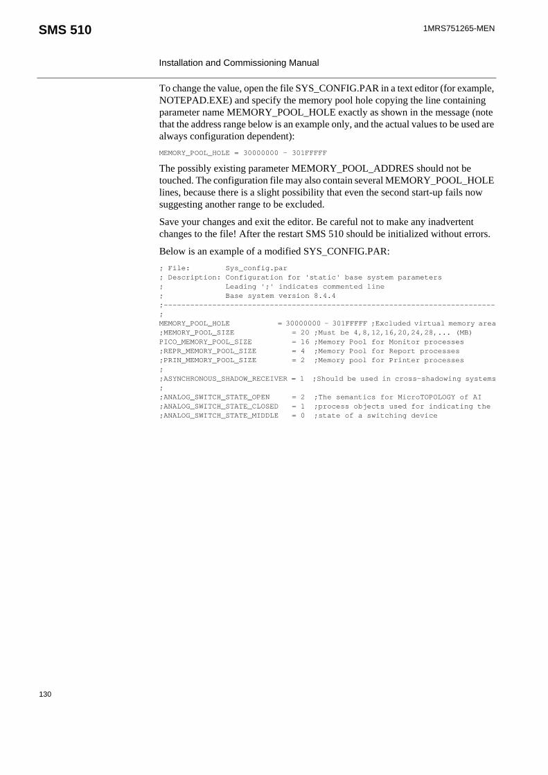
1MRS751265-MEN
Installation and Commissioning Manual
SMS 510
To change the value, open the file SYS_CONFIG.PAR in a text editor (for example, NOTEPAD.EXE) and specify the memory pool hole copying the line containing parameter name MEMORY_POOL_HOLE exactly as shown in the message (note that the address range below is an example only, and the actual values to be used are always configuration dependent):MEMORY_POOL_HOLE = 30000000 - 301FFFFF
The possibly existing parameter MEMORY_POOL_ADDRES should not be touched. The configuration file may also contain several MEMORY_POOL_HOLE lines, because there is a slight possibility that even the second start-up fails now suggesting another range to be excluded.
Save your changes and exit the editor. Be careful not to make any inadvertent changes to the file! After the restart SMS 510 should be initialized without errors.
Below is an example of a modified SYS_CONFIG.PAR:; File: Sys_config.par; Description: Configuration for 'static' base system parameters; Leading ';' indicates commented line; Base system version 8.4.4;---------------------------------------------------------------------------;MEMORY_POOL_HOLE = 30000000 - 301FFFFF ;Excluded virtual memory area;MEMORY_POOL_SIZE = 20 ;Must be 4,8,12,16,20,24,28,... (MB)PICO_MEMORY_POOL_SIZE = 16 ;Memory Pool for Monitor processes ;REPR_MEMORY_POOL_SIZE = 4 ;Memory Pool for Report processes;PRIN_MEMORY_POOL_SIZE = 2 ;Memory pool for Printer processes;;ASYNCHRONOUS_SHADOW_RECEIVER = 1 ;Should be used in cross-shadowing systems;;ANALOG_SWITCH_STATE_OPEN = 2 ;The semantics for MicroTOPOLOGY of AI;ANALOG_SWITCH_STATE_CLOSED = 1 ;process objects used for indicating the;ANALOG_SWITCH_STATE_MIDDLE = 0 ;state of a switching device
130

1MRS751265-MEN SMS 510 Installation and Commissioning Manual
6. Uninstallation
6.1. OverviewThe uninstallation is done by means of a special-purposed program (Uninstaller) designed for the removal of software products. Each product comes with its own designated Uninstaller installed with the product.
6.2. FeaturesThe Uninstaller has the following features:
• Removal of files, folders, services, registry keys, user accounts• Logging of uninstallation operations• Validation of the integrity of the data the uninstallation is based on• Ability to cancel/abort the uninstallation• Ability to re-run the uninstallation as long as the data the uninstallation is based
on is available• Detection of the need to reboot• Graphical user interface (Uninstall Wizard)
6.3. Scope of uninstallationUninstalling the product comprises the following operations:
• Permanent removal of the product's main installation directory• Permanent removal of the product's program folder(s)• Permanent removal of the product's key system registry entries • Permanent removal of the shared MicroSCADA components. This covers for
instance the MicroSCADA Service and MicroSCADA User Account. However, the shared MicroSCADA components are removed only if the product utilizes the MicroSCADA Service and no other such a product has been installed.
6.4. Preparing for uninstallationPrior to starting the uninstallation, it is recommended to:
• Have backups of the data produced with the product. The only way to recover the data is to recover it from your personal backups.
• Close all other applications that are running • Logon from an administrator account
Note that SMS 510 uninstallation covers only the main SMS 510 product, not the additional software mentioned in Chapter 4. The uninstallation of Parameter Setting Tool, CAP 2/316, REB500 Selector and HMI500 - REBWIN is done separately by means of the related uninstaller applications or by other related instructions provided.
131

1MRS751265-MEN
Installation and Commissioning Manual
SMS 510
6.5. Backing up the dataIt is recommended to use the Project Export/Import Tool to backup the created project(s). More information about the Project Export/Import Tool can be found in the Operator's Manual.
In addition to the project data, there are also two optional data locations to be considered before uninstallation. These locations include data, which may be useful later, but which is not mandatory from the project's point of view:
1. If the user-defined application libraries for REC 52x, REF 54x and/or REM 54x relay types need to be saved, it is recommended to export each configuration to a safe location by means of the object type's "Apl Utils" function. More information on this can be found in the Tools for Relays and Terminals manual.
2. If the uploaded disturbance recordings need to be saved, the contents of the "\SMS510\Apl\SMS510\RECORDER" directory must be copied to a safe place.
Make sure you store the data outside the product's main installation directory (installation drive/SMS 510 directory).
6.6. Cancelling/aborting the uninstallationAs long as the Cancel button is enabled on the Uninstall Wizard, clicking on it causes the Uninstaller to prompt you to confirm that you wish to stop prematurely.
At a certain point, the Cancel button will be disabled during the actual uninstallation. This is because at that point, the Uninstaller removes the mandatory components for re-running itself.
6.7. Starting the uninstallationThe Uninstaller is started via Control Panel's Add/Remove Programs applet as shown below in Figure 6.7.-1:
Fig. 6.7.-1 Add/Remove Programs applet
If you abort the uninstallation when the removal has already been started, you must not try to use the product before you have fully re-installed it.
132

1MRS751265-MEN SMS 510 Installation and Commissioning Manual
Prior to entering the Uninstall Wizard, the Uninstaller prompts you whether to proceed as shown below in Figure 6.7.-2:
Fig. 6.7.-2 The Confirmation dialog
6.8. Uninstall WizardThis section describes the Uninstall Wizard in detail.
6.8.1. OverviewThe Uninstall Wizard comprises a series of dialogs which guide you through the steps required to uninstall the product. Your computer setup will be modified only after you make the decision to remove the product.
In addition to the dialogs depicted below, the Uninstaller may display other dialogs not documented here. Such dialogs appear, for example, if you decide to abort the uninstallation or unrecoverable error(s) occur at any point of the program execution.
Generally, you will be clearly notified about the end-result of the uninstallation and about the status of your computer setup.
6.8.2. Uninstall Wizard dialogsThe sequence of the dialogs that appear upon a successful operation is described below.
6.8.2.1. Welcome to UninstallThis dialog welcomes you to the uninstallation (see Figure 6.8.2.1.-1). Just click Next to proceed to the next dialog.
133

1MRS751265-MEN
Installation and Commissioning Manual
SMS 510
Fig. 6.8.2.1.-1 The Welcome dialog
6.8.2.2. Backup NoticeThis dialog notifies you to ensure backups of the data produced with the product (see Figure 6.8.2.2.-1). All directories subject to removal are displayed. Notice that if you have installed the product in multiple locations (various drives), the list contains all of the main installation directories your installations have used. Be sure that you do not lose data accidentally.
Fig. 6.8.2.2.-1 The Backup Notice dialog
134

1MRS751265-MEN SMS 510 Installation and Commissioning Manual
6.8.2.3. Ready to UninstallThis is the dialog where you start the actual uninstallation by clicking on Uninstall (see Figure 6.8.2.3.-1). Remember that by clicking on Uninstall, your product installation becomes immediately unusable.
Fig. 6.8.2.3.-1 The Ready to Uninstall dialog
6.8.2.4. Uninstall in ProgressThis dialog is displayed while the Uninstaller removes the product (see Figure 6.8.2.4.-1).
This dialog displays the progress of the uninstallation while the product is being removed. To abort the uninstallation, click on Cancel (if enabled) and confirm the abort when prompted to do so.
135

1MRS751265-MEN
Installation and Commissioning Manual
SMS 510
Fig. 6.8.2.4.-1 The Uninstall in Progress dialog
6.8.2.5. Uninstall CompletedThis dialog is displayed when the Uninstaller has successfully removed the product (see Figure 6.8.2.5.-1). You may view the produced log file, if you wish.
Fig. 6.8.2.5.-1 The Uninstall Completed dialog
136

1MRS751265-MEN SMS 510 Installation and Commissioning Manual
6.9. RebootingUninstaller operations may require a reboot in order to be fully carried out. Under such circumstances, the Uninstaller will prompt you to reboot the computer, when you exit the Uninstall Wizard.
6.10. TroubleshootingIn case the uninstallation fails, please ensure that the produced log file remains available to aid in troubleshooting. It will be the only source of information usable for the purpose. You may open the log file in a text editor and save it in a location where it will not be modified further.
It is mandatory to reboot the computer at least prior to installing any new software in the computer. Failure to adhere to that may cause malfunctioning software installations.
137


1MRS751265-MEN SMS 510 Installation and Commissioning Manual
7. Troubleshooting installation
This chapter provides information that aims to help your recovering from problems that you have encountered during the SMS 510 installation.
7.1. Incorrect operating system detectedIf you attempt to install SMS 510 on an operating system other than Windows NT 4.0, Windows 2000 or Windows XP, the installation notifies you with the message. Ensure correct computer configuration and rerun the installation.
7.2. Incorrect operating system version detectedIf you attempt to install SMS 510 on a Windows NT operating system lower than version 4.0, the installation notifies you with the message. Ensure correct computer configuration and rerun the installation.
7.3. Insufficient user rights to installIf you have logged on to your computer having non-administrator rights, the installation notifies you with the message shown in Figure 7.3.-1.
Fig. 7.3.-1 Insufficient user rights to install SMS 510
To recover, click OK and logon to the computer having administrator rights and restart the installation.
7.4. MicroSCADA service is runningIf the MicroSCADA service is running when you start the SMS 510 installation, you are notified with the message shown in Figure 7.4.-1.
You may erroneously receive this notification even if you have logged on with administrator rights. When encountering such behaviour, the problem most probably relates to the TEMP environment variable setting on your computer (see Section “TEMP environment variable” on page 144 for instructions to recover).
139

1MRS751265-MEN
Installation and Commissioning Manual
SMS 510
Fig. 7.4.-1 MicroSCADA service must be shut down before continuing with the installation
In order to continue, exit the application currently utilizing the MicroSCADA service and click Yes. The application is one of the applications listed in the message. Notice that you cannot continue with the installation while the service is executing. To exit the installation, click No.
7.5. Failing to install the MicroSCADA serviceIf the installation of the MicroSCADA service does not succeed, the installation displays the message shown in Figure 7.5.-1.
Fig. 7.5.-1 MicroSCADA service installation has failed
The most probable reason for this is that the MicroSCADA service has started during the SMS 510 installation. In order to recover from this, click OK to dismiss the message and exit the installation by clicking Cancel on the Installing progress dialog. Restart the installation and install at least the Base system.
140

1MRS751265-MEN SMS 510 Installation and Commissioning Manual
7.6. Troubleshooting destination drive error messages Depending on the current destination drive setting and your computer configuration, you may be notified with a message that SMS 510 cannot be installed to:
• a CD-ROM drive• a non-NTFS drive• a network drive• a removable media drive• a virtual (substituted) drive
To proceed, click OK and select a suitable destination drive in the Installation Wizard's Select Destination Drive dialog.
7.7. Insufficient disk spaceProvided that the selected destination drive does not contain sufficient free disk space, the installation displays the dialog shown in Figure 7.7.-1.
Fig. 7.7.-1 Insufficient disk space to install
The available options are:
• Abort, which aborts the installation immediately. Note! Your computer configuration has not yet been modified at this point, so you can safely select this option to exit installation.
• Retry, which checks the disk space and redisplays this dialog if the amount of available disk space has not increased sufficiently. Otherwise, the software installation continues normally.
• Ignore, which causes the installation blindly to continue copying the software to the destination. Notice that it is not recommended to use this option as the installation might eventually fail in its operation.
7.8. No suitable destination drive availableIf your computer does not contain any drives formatted to NTFS and you have not installed SMS 510 before, the installation displays the message shown in Figure 7.8.-1.
141

1MRS751265-MEN
Installation and Commissioning Manual
SMS 510
Fig. 7.8.-1 No suitable destination drive available for installation
Click OK to dismiss the message and to exit the installation.
In order to install SMS 510, you must format a drive to NTFS. Use the operating system tools to accomplish this task.
7.9. Incompatible SYS 500 and/or COM 500 installedDuring the start-up of the installation, you may see the notification displayed in Figure 7.9.-1.
Fig. 7.9.-1 Product upgrades will be required if SMS 510 is installed
As stated, the old versions of SYS 500 and COM 500 cannot be used if you install SMS 510. If you are unsure about installing SMS 510, click No to exit the installation. Otherwise, click Yes to continue with the installation.
Provided that you choose to install SMS 510, remember that SYS 500 and COM 500 must be updated to the respective versions stated in the message before you can continue using those products.
142

1MRS751265-MEN SMS 510 Installation and Commissioning Manual
7.10. Galaxy Debug window during first start-upIf a Galaxy Debug window is shown when you try to start SMS 510 the first time after its installation, you must restart your computer and try again. See Figure 7.10.-1:
Fig. 7.10.-1 Galaxy Debug window
7.11. CAP 2/316 does not startIf the CAP216/316 tool does not start as it should, the reason may be that the DCOM identity password and the MicroSCADA user password are not the same. Make sure that the passwords are configured according to Section 4.4.2.10. and Section 5.7.3. of this manual.
7.12. Error when opening Remote Connection Properties dialogIn some circumstances the private phonebook of SMS 510 may get corrupted. The Remote Connection Properties dialog cannot be opened due to this corruption and this kind of error will be shown instead:Error: 421 SCIL_ATTRIBUTE_NOT_FOUNDIn program: START_DLG\TOOLMGR\TREENAVIG_4\TOOLBAR\CP_REMOTELIST.UPDATELISTOn line: 29 .Modify This = List(Id2 = Cmd_RemoteList_iVal:vId,-
This can be solved only by manually deleting the private phonebook file \SMS510\Services\Communication\Use\BGU_CMGR_RAS.PBK and then restarting SMS 510. After this the remote connection settings must be redefined.
7.13. Miscellaneous
7.13.1. Repaired operating system installationsIf your computer experiences operating system failures and you repair the operating system installation, it is recommended that you reinstall at least the following options of the SMS 510 in order to guarantee correct installation of SMS 510:
• Base System• REB 500 / RE.x16 Support
In addition, reinstall the Parameter Setting Tool (PST).
143

1MRS751265-MEN
Installation and Commissioning Manual
SMS 510
7.13.2. TEMP environment variableThe TEMP environment variable must be defined on your computer and its content must have reference to an existing directory to which you have read/write access. Also, make sure that the drive on which this directory exists is not running out of storage capacity.
To define the TEMP environment variable on Windows NT 4.0:1. Open the System applet from the Control Panel.2. Choose the Environment page as shown in Figure 7.13.2.-1 and locate the
TEMP variable from one of the lists. The setting may be defined both as a System and a User variable. If found, the User variable setting overrides the respective System variable setting.
Fig. 7.13.2.-1 TEMP environment variable setting
3. Make sure that the defined directory actually exists on your computer. In the figure above, the directory is 'C:\TEMP'. Use e.g. the Windows NT Explorer to browse for this directory.
144

1MRS751265-MEN SMS 510 Installation and Commissioning Manual
To define the TEMP environment variable on Windows 2000:1. Open the System applet from the Control Panel.2. Select the Advanced page as shown in Figure 7.13.2.-2.
Fig. 7.13.2.-2 Advanced page of System Properties
3. Choose the Environment Variables and locate TEMP variable from the list (see Figure 7.13.2.-3). Verify that you have read/write access to the referenced directory and that there is enough storage capacity.
145

1MRS751265-MEN
Installation and Commissioning Manual
SMS 510
Fig. 7.13.2.-3 TEMP environment variable setting in Windows 2000
To define the TEMP environment variable on Windows XP:1. Open the System applet from the Control Panel.2. Select the Advanced page as shown in Figure 7.13.2.-4.
146

1MRS751265-MEN SMS 510 Installation and Commissioning Manual
Fig. 7.13.2.-4 Advanced page of System Properties in Windows XP
3. Choose the Environment Variables and locate TEMP variable from the list (see Figure 7.13.2.-5). Verify that you have read/write access to the referenced directory and that there is enough storage capacity.
147

1MRS751265-MEN
Installation and Commissioning Manual
SMS 510
Fig. 7.13.2.-5 TEMP environment variable setting in Windows XP
148

1MRS751265-MEN SMS 510 Installation and Commissioning Manual
8. Index
AAdditional installation applications
Accessing ............................................................................................ 38Adobe Acrobat Reader
Installing ............................................................................................. 38
BBaud rate ................................................................................................... 45
CCAP 2/316 ................................................................................................ 21CAP2/316 tool .......................................................................................... 12Commissioning
Installing LON cards .......................................................................... 59System Configuration tool .................................................................. 47
Communication configurationMaximum number of communication channels ................................. 45
Communication protocolSpecifying for a serial port ................................................................. 52
Configuring Loopback Adapter in Windows 2000 ................................ 108Considerations when specifying IP addresses in Windows 2000 .......... 111Current version
Definition ............................................................................................ 17
DData bits .................................................................................................... 45Data buffering setting ............................................................................... 45Destination drive
Default destination drive .................................................................... 20No applicable destination drive on computer ................................... 141Selecting the drive .............................................................................. 29Warnings ........................................................................................... 141
Dialing-UpRAS .................................................................................................. 129
Disk spaceError .................................................................................................. 141
DisplayHardware requirements ...................................................................... 15
Distributed COM (DCOM) ...................................................................... 78
FFile system
Hardware requirements ...................................................................... 15
149

1MRS751265-MEN Installation and Commissioning Manual
SMS 510
GGalaxy Debug window ........................................................................... 143
HHang-Up
RAS .................................................................................................. 129SMS 510 ........................................................................................... 129
Hard disk spaceHardware requirements ...................................................................... 15
HardwareHardware delivered with SMS 510 .................................................... 13Hardware requirements ...................................................................... 15
HMI500 - REBWIN ........................................................................... 20, 21HV/Collect Tool. ...................................................................................... 12
IInput/output (I/O) addresses ..................................................................... 45Installation
Access to SMS 510 manuals .............................................................. 37Accessing additional installation applications ................................... 38Accessing tools outside SMS 510 ...................................................... 39Cancelling the installation .................................................................. 34Executing MicroSCADA Service Access Manager ........................... 39Executing MicroSCADA User Password tool ................................... 39Grating access to start and stop the MicroSCADA service ............... 31Incorrect operating system ............................................................... 139Incorrect operating system version .................................................. 139Indication of completion .................................................................... 33Indication of system reboot ................................................................ 34Install Adobe Acrobat Reader ............................................................ 38Install Internet Explorer 4.01 SP2 ...................................................... 38Installation applications needed to install SMS 510 .......................... 11Installation Wizard ............................................................................. 22Install-time errors ............................................................................. 139Install-time notifications .................................................................. 139Insufficient user rights ...................................................................... 139modems .............................................................................................. 85Outline of the installation procedure .................................................. 20Preparing the computer for the SMS 510 installation ........................ 17Progress indication ............................................................................. 30RAS .................................................................................................... 84SMS 510 program folder .................................................................... 37SMS 510 program folder shortcut ...................................................... 39Specifying the MicroSCADA user ..................................................... 30Starting the main installation application ........................................... 21Starting the PST installation application ............................................ 35
150

1MRS751265-MEN SMS 510 Installation and Commissioning Manual
Troubleshooting the installation ....................................................... 139Installation options
Selecting the software to install .......................................................... 28Installation Wizard ................................................................................... 22Installation Wizard dialog boxes
Destination Drive ................................................................................ 29Main dialog box for non-forced installation ....................................... 28Main dialog box for the forced installation ........................................ 27Product License Agreement ............................................................... 23System Information dialog box 1 ....................................................... 24System Information dialog box 2 ....................................................... 25System Information dialog box 3 ....................................................... 26Welcome ............................................................................................. 22
InstallingModems .............................................................................................. 85MS Loopback Adapter ....................................................................... 91RAS .................................................................................................... 88Remote Access Service ...................................................................... 88
Installing the CAP 2/316 software ........................................................... 35Installing the HMI500 - REBWIN software ............................................ 36Installing the REB500 Selector software ................................................. 35Interdependencies
CAP 501 ............................................................................................. 18CAP 505 ............................................................................................. 18COM 500 ............................................................................................ 18Controlling access to MicroSCADA service ...................................... 18Incompatible kernel revision of COM 500 8.4.2A or older ............... 19Incompatible kernel revision of SYS 500 8.4.2A or older ................. 19Incompatible kernel revisions used in other products ........................ 19MicroSCADA service ........................................................................ 18Overview ............................................................................................ 18SYS 500 .............................................................................................. 18
Internet Explorer 4.01 SP2Installing ............................................................................................. 38
Interrupt request line (IRQ) ...................................................................... 45Invalid destination drives ....................................................................... 141ISA
Hardware requirements ...................................................................... 15
LLicense information
Entering .............................................................................................. 42Failing to apply ................................................................................... 44
LON adapter supportPCC-10 PC Card ................................................................................. 46PCLTA-20 PC LonTalk Adapter ........................................................ 46
151

1MRS751265-MEN Installation and Commissioning Manual
SMS 510
PCMCIA ............................................................................................ 46LON communication
Assigning time synchronization settings ............................................ 56Communication software components ............................................... 46
LonWorks® Plug’n Play control panel .................................................... 56
MManuals
Accessing manuals ............................................................................. 37Memory
Hardware requirements ...................................................................... 15MicroSCADA service
Controlling access to MicroSCADA service ..................................... 18Error ................................................................................................. 140Granting access to start and stop the MicroSCADA service ............. 31Limitation ........................................................................................... 18Warning ............................................................................................ 139
MicroSCADA Service Access ManagerExecuting ............................................................................................ 39Using the manager .............................................................................. 31
MicroSCADA userSpecifying the MicroSCADA user account ....................................... 30
MicroSCADA User Password toolExecuting ............................................................................................ 39
ModemHardware requirements ...................................................................... 15
ModemsInstallation .......................................................................................... 85Installing ............................................................................................. 85
MouseHardware requirements ...................................................................... 15
MS Loopback AdapterInstalling ............................................................................................. 91
MS Loopback Adapter driver ................................................................... 84
NNetwork adapter card
Hardware requirements ...................................................................... 15NI Application .................................................................................... 65, 70Not enough disk space ............................................................................ 141Notification Window ........................................................................ 39, 129
OOperating System
Reboot after installation ..................................................................... 34
152

1MRS751265-MEN SMS 510 Installation and Commissioning Manual
PParameter Setting Tool ............................................................................. 21Parameter Setting Tool (PST) .................................................... 11, 12, 143Parity ......................................................................................................... 45PCC-10 PC Card
Installing and configuring ................................................................... 63PCLTA-20 Card
Configuring ......................................................................................... 68Processor
Hardware requirements ...................................................................... 15Product license
License label ....................................................................................... 18Program CD
License label ....................................................................................... 18Program folder
Shortcut to program folder ................................................................. 39Project Export/Import Tool .................................................................... 132
RRAS
Automatic start-up in the server computer ......................................... 95Diagnosing RAS ................................................................................. 96Dial-in permissions in the RAS server computer ............................... 96Dialing-Up ........................................................................................ 129Entering TCP/IP addresses ................................................................. 91Hang-Up ........................................................................................... 129Installation .......................................................................................... 84Installing ............................................................................................. 88Network Configuration ....................................................................... 90Phonebooks in SMS 510 .................................................................. 129
RAS ClientSpecifying port usage ......................................................................... 90
RAS ServerEntering TCP/IP addresses ................................................................. 91Installing MS Loopback Adapter ....................................................... 91Specifying port usage ......................................................................... 90
RAS/Modem installation on Windows 2000 ............................................ 98RAS/Modem installation on Windows XP ............................................. 112RE. 216/316 .............................................................................................. 21REB500 Selector .......................................................................... 12, 20, 21REBWIN HMI tool .................................................................................. 12Remote Access Admin tool ...................................................................... 96Remote Access Service
Automatic start-up in the server computer ......................................... 95Diagnosing RAS ................................................................................. 96
Remote Access Service (RAS) ................................................................. 84
153

1MRS751265-MEN Installation and Commissioning Manual
SMS 510
RequirementsAdditional requirements ..................................................................... 16Hardware requirements ...................................................................... 15MicroSCADA service status .............................................................. 16Software requirements ........................................................................ 15User rights during installation ............................................................ 16
SSerial ports
Adding in SMS 510 ............................................................................ 51Advanced port settings ....................................................................... 45Basic port settings .............................................................................. 45Configuring in SMS 510 .................................................................... 52Deleting in SMS 510 .......................................................................... 53Hardware requirements ...................................................................... 15Maximum number of serial ports in SMS 510 ................................... 51SMS 510 vs. operating system serial port configuration ................... 45Specifying the Communication protocol ........................................... 52
Service executing during installation ..................................................... 139Service installation failed ....................................................................... 140SMS 510
Commissioning .................................................................................. 41Communication channels ................................................................... 45Communication support ..................................................................... 44Dialing-Up ........................................................................................ 129Hang-Up ........................................................................................... 129Installation applications needed to install SMS 510 .......................... 11Licensing the product ......................................................................... 41LON communication .......................................................................... 46Maximum number of communication channels ................................. 45Private phonebooks .......................................................................... 129Program folder ................................................................................... 37Serial port communication ................................................................. 45Time synchronization ......................................................................... 46Time synchronization over LON ........................................................ 46Time synchronization over SPA ........................................................ 47
SoftwareContents .............................................................................................. 11
SPA communicationAssigning time synchronization settings ............................................ 52
SPA Terminal Emulator ........................................................................... 39Starting the CAP 2/316 installation .......................................................... 35Starting the HMI500 - REBWIN installation ........................................... 36Starting the REB500 Selector installation ................................................ 35Stop bits .................................................................................................... 45System Configuration tool
154

1MRS751265-MEN SMS 510 Installation and Commissioning Manual
Accessing the tool ............................................................................... 48Assigning LON time synchronization settings ................................... 56Assigning SPA time synchronization settings .................................... 52Assigning Subnet/Node settings ......................................................... 55Discarding changes to the configuration ............................................ 59General ............................................................................................... 48LON page ........................................................................................... 53Saving the configuration ..................................................................... 58Selecting the LON adapter ................................................................. 54Serial ports page ................................................................................. 50
TTCP/IP protocol ........................................................................................ 90Time synchronization
Advanced mode .................................................................................. 57Basic mode ......................................................................................... 57In SMS 510 ......................................................................................... 46Time synchronization over LON ........................................................ 46Time synchronization over SPA ......................................................... 47
TroubleshootingIncompatible kernel revisions in other products .............................. 142Invalid types of destination drives .................................................... 141LON .................................................................................................... 74No applicable destination drive on computer ................................... 141Not enough disk space ...................................................................... 141Repaired operating system installation ............................................. 143Service installation failed ................................................................. 140
UUninstall Wizard ..................................................................................... 133Uninstallation
Backing up the data .......................................................................... 132Cancelling/aborting the uninstallation .............................................. 132Preparing for uninstallation .............................................................. 131Rebooting ......................................................................................... 137Scope of uninstallation ..................................................................... 131Starting the uninstallation ................................................................. 132Troubleshooting ................................................................................ 137
Uninstaller ...................................................................................... 131, 132User rights
ErrorInsufficient rigths to install 139
Granting access to start and stop the MicroSCADA service .............. 31Using USB ports ....................................................................................... 45
WWindows 2000
155

1MRS751265-MEN Installation and Commissioning Manual
SMS 510
Considerations when specifying IP addresses .................................. 111Installation of the PCLTA-20 adapter on Windows 2000 .................. 59
Windows XP .......................................................................................... 112Configuring Loopback Adapter ....................................................... 125Considerations when specifying IP addresses .................................. 128Incoming connections
116Installing a modem ........................................................................... 112Installing the Microsoft Loopback Adapter ..................................... 122
156


ADP.FFTeFw
1MR
S75
1265
EN
08.
2004
BB Oyistribution Automation O. Box 699I-65101 VaasaINLANDl. +358 10 22 11
ax. +358 10 224 1094ww.abb.com/substationautomation