installation and commissioning - hblcs.hbl.in/docs/installation_and_commissioning.pdfinstallation...
TRANSCRIPT
Installation and Commissioning
Installation and Commissioning must be carried out by qualified/competent authorized personnel.Observe the relevant installation drawing before choosing an installation location, determining space requirements before performing the installation.The floor must be suitable for battery installation; it must:– have a suitable load-carrying capacity,– the surface must be at equal level , be as free from vibration as possible (otherwise a special rack is required).
Environment
Passageway width
HBL®
Ventilation source
Sufficient room ventilation is absolutely required to limit the hydrogen concentration (H2 concentration) in the ambient air of the battery room to a value of <1% by volume.Hydrogen is lighter than air. Make sure that hydrogen does not accumulate (e.g., in the ceiling area). Ventilation and De-aeration openings should be placed near the ceiling.
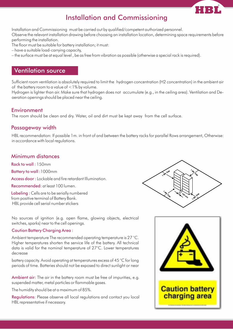
HBL recommendation: If possible 1m. in front of and between the battery racks for parallel Rows arrangement, Otherwise: in accordance with local regulations.
Rack to wall : 150mm
Battery to wall : 1000mm
Access door : Lockable and fire retardant Illumination.
Recommended: at least 100 lumen.
Labeling : Cells are to be serially numberedfrom positive terminal of Battery Bank. HBL provide cell serial number stickers
The room should be clean and dry. Water, oil and dirt must be kept away from the cell surface.
Minimum distances
No sources of ignition (e.g. open flame, glowing objects, electrical switches, sparks) near to the cell openings.
Caution Battery Charging Area :
Ambient temperature The recommended operating temperature is 27 °C. Higher temperatures shorten the service life of the battery. All technical data is valid for the nominal temperature of 27°C. Lower temperatures decrease
battery capacity. Avoid operating at temperatures excess of 45 °C for long periods of time. Batteries should not be exposed to direct sunlight or near
Ambient air: The air in the battery room must be free of impurities, e.g. suspended matter, metal particles or flammable gases.
The humidity should be at a maximum of 85%.
Regulations: Please observe all local regulations and contact you local HBL representative if necessary.
Ventilation
It is impossible to stop gases from being generated while over charging batteries; therefore, the hydrogen
concentration in the air must be reduced with sufficient ventilation.
Do not use sparking equipment near batteries. The following could act as sources of ignition open flames
– flying sparks
– electrical, sparking equipment
– mechanical, sparking equipment
– electrostatic charge.
Observe the following measures to prevent any re:
– sufficient natural or technical ventilation
– no heating using open flames or glowing objects (T > 300°C)
– anti-static clothing, shoes and gloves (according to applicable DIN and EN regulations)
– hand-held lights with power cable without switch (protection class II)
– hand-held lights with battery (protection category Ip54)
– warning and regulatory signs.
The ventilation requirements for battery rooms, cabinets or compartments are based on the required reduction of the
concentration of hydrogen generated during charging and safety factors which include battery ageing and the
potential for fault (“worst case”).
Installation tools and equipment
The batteries are delivered on pallets and the required accessories are located in separate packaging units.
Observe all information from the previous sections.
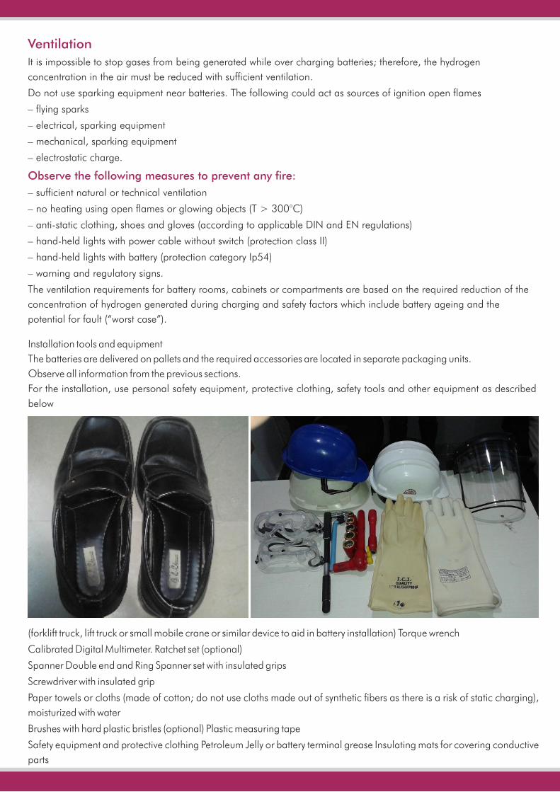
For the installation, use personal safety equipment, protective clothing, safety tools and other equipment as described
below
(forklift truck, lift truck or small mobile crane or similar device to aid in battery installation) Torque wrench
Calibrated Digital Multimeter. Ratchet set (optional)
Spanner Double end and Ring Spanner set with insulated grips
Screwdriver with insulated grip
Paper towels or cloths (made of cotton; do not use cloths made out of synthetic fibers as there is a risk of static charging),
moisturized with water
Brushes with hard plastic bristles (optional) Plastic measuring tape
Safety equipment and protective clothing Petroleum Jelly or battery terminal grease Insulating mats for covering conductive
parts
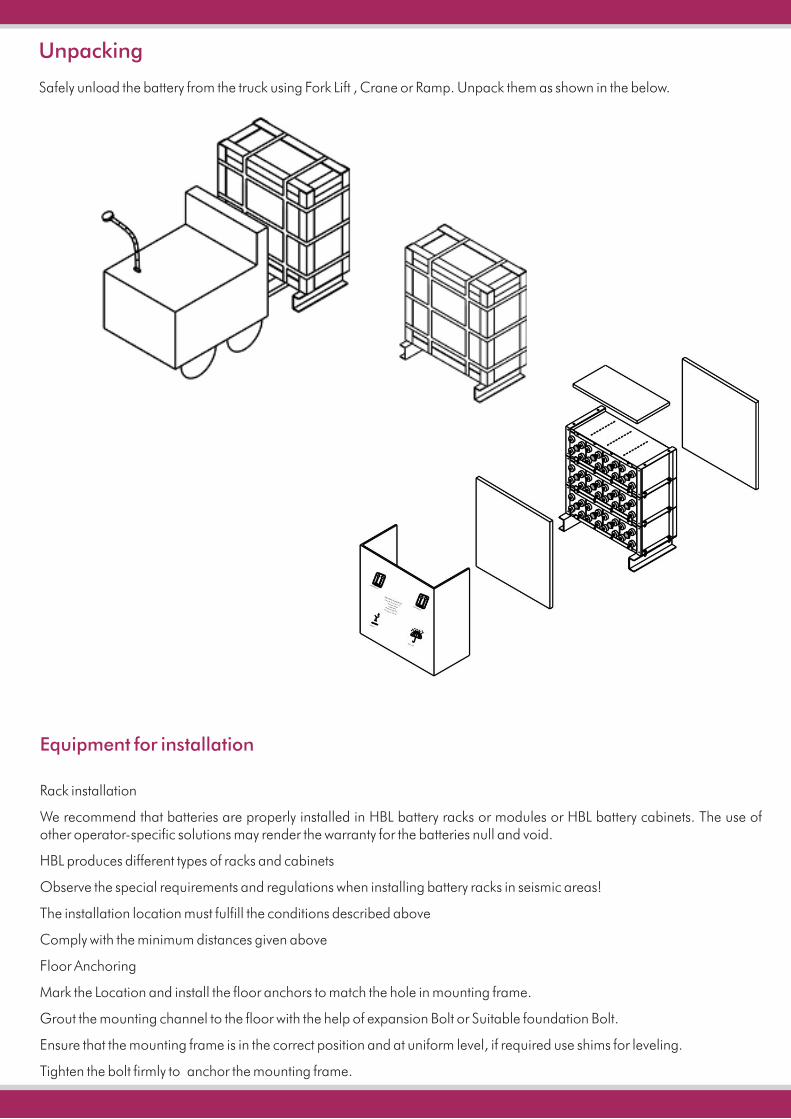
Unpacking
Safely unload the battery from the truck using Fork Lift , Crane or Ramp. Unpack them as shown in the below.
Equipment for installation
Rack installation
We recommend that batteries are properly installed in HBL battery racks or modules or HBL battery cabinets. The use of other operator-specific solutions may render the warranty for the batteries null and void.
HBL produces different types of racks and cabinets
Observe the special requirements and regulations when installing battery racks in seismic areas!
The installation location must fulfill the conditions described above
Comply with the minimum distances given above
Floor Anchoring
Mark the Location and install the floor anchors to match the hole in mounting frame.
Grout the mounting channel to the floor with the help of expansion Bolt or Suitable foundation Bolt.
Ensure that the mounting frame is in the correct position and at uniform level, if required use shims for leveling.
Tighten the bolt firmly to anchor the mounting frame.
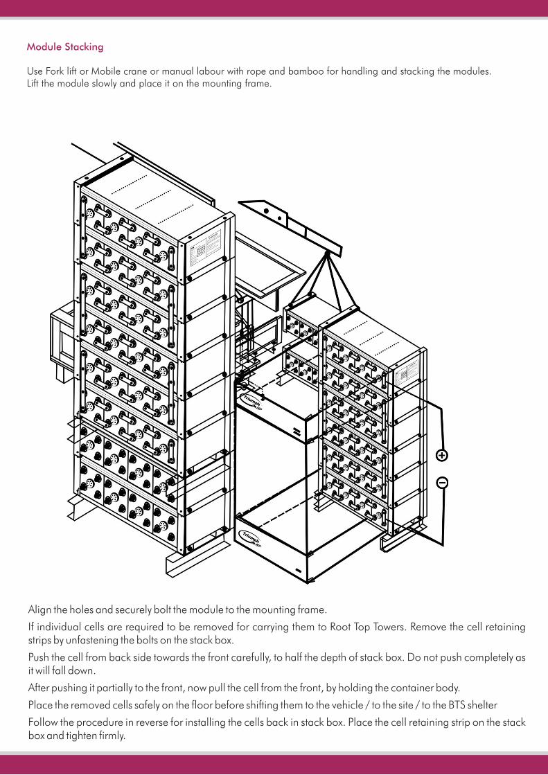
Module Stacking
Use Fork lift or Mobile crane or manual labour with rope and bamboo for handling and stacking the modules.Lift the module slowly and place it on the mounting frame.
Align the holes and securely bolt the module to the mounting frame.
If individual cells are required to be removed for carrying them to Root Top Towers. Remove the cell retaining strips by unfastening the bolts on the stack box.
Push the cell from back side towards the front carefully, to half the depth of stack box. Do not push completely as it will fall down.
After pushing it partially to the front, now pull the cell from the front, by holding the container body.
Place the removed cells safely on the floor before shifting them to the vehicle / to the site / to the BTS shelter
Follow the procedure in reverse for installing the cells back in stack box. Place the cell retaining strip on the stack box and tighten firmly.
Refer relevant HBL I&O Manual, supplied along with respective battery system, for relevant other installation instructions
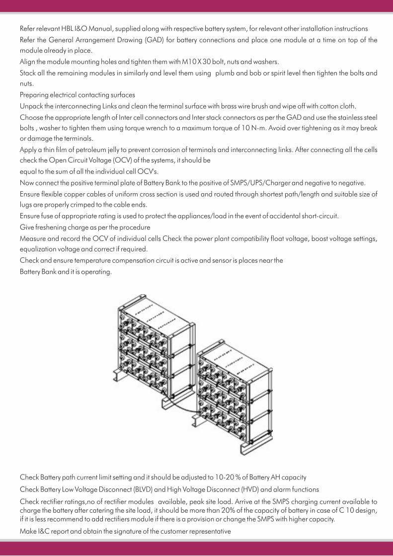
Refer the General Arrangement Drawing (GAD) for battery connections and place one module at a time on top of the
module already in place.
Align the module mounting holes and tighten them with M10 X 30 bolt, nuts and washers.
Stack all the remaining modules in similarly and level them using plumb and bob or spirit level then tighten the bolts and
nuts.
Preparing electrical contacting surfaces
Unpack the interconnecting Links and clean the terminal surface with brass wire brush and wipe off with cotton cloth.
Choose the appropriate length of Inter cell connectors and Inter stack connectors as per the GAD and use the stainless steel
bolts , washer to tighten them using torque wrench to a maximum torque of 10 N-m. Avoid over tightening as it may break
or damage the terminals.
Apply a thin film of petroleum jelly to prevent corrosion of terminals and interconnecting links. After connecting all the cells
check the Open Circuit Voltage (OCV) of the systems, it should be
equal to the sum of all the individual cell OCV's.
Now connect the positive terminal plate of Battery Bank to the positive of SMPS/UPS/Charger and negative to negative.
Ensure flexible copper cables of uniform cross section is used and routed through shortest path/length and suitable size of
lugs are properly crimped to the cable ends.
Ensure fuse of appropriate rating is used to protect the appliances/load in the event of accidental short-circuit.
Give freshening charge as per the procedure
Measure and record the OCV of individual cells Check the power plant compatibility float voltage, boost voltage settings,
equalization voltage and correct if required.
Check and ensure temperature compensation circuit is active and sensor is places near the
Battery Bank and it is operating.
Check Battery path current limit setting and it should be adjusted to 10-20 % of Battery AH capacity
Check Battery Low Voltage Disconnect (BLVD) and High Voltage Disconnect (HVD) and alarm functions
Check rectifier ratings,no of rectifier modules available, peak site load. Arrive at the SMPS charging current available to charge the battery after catering the site load, it should be more than 20% of the capacity of battery in case of C 10 design, if it is less recommend to add rectifiers module if there is a provision or change the SMPS with higher capacity.
Make I&C report and obtain the signature of the customer representative