installation & maintenance instructions minitrac 31
TRANSCRIPT

Installation & Maintenance Instructions
MINITRAC 31Foundation Fieldbus
Radiation-based sensor for density measurement
Reading OfficeCutbush Park, Danehill, Lower Earley,Reading, Berkshire. RG6 4UT. UK.Tel: +44 (0)118 9311188 Email: [email protected]
Aberdeen OfficeUnit 6 Airside Business Park, Kirkhill Industrial Estate, Dyce, Aberdeen. AB21 0GT. UK.Tel: +44 (0)1224 725999Email: [email protected]
Internet: www.able.co.uke-procurement: www.247able.comRegistered in England No: 01851002VAT No: GB 417 2481 61

2
Contents
MINITRAC 31 • Foundation Fieldbus
41782-EN-130430
Contents1 About this document
1.1 Function ........................................................................................................................... 41.2 Target group ..................................................................................................................... 41.3 Symbolism used ............................................................................................................... 4
2 For your safety2.1 Authorised personnel ....................................................................................................... 52.2 Appropriate use ................................................................................................................ 52.3 Warning about incorrect use ............................................................................................. 52.4 General safety instructions ............................................................................................... 52.5 CE conformity ................................................................................................................... 62.6 NAMUR recommendations .............................................................................................. 62.7 Environmental instructions ............................................................................................... 6
3 Product description3.1 Configuration .................................................................................................................... 73.2 Principle of operation........................................................................................................ 83.3 Packaging, transport and storage ................................................................................... 103.4 Accessories and replacement parts ............................................................................... 103.5 Corresponding source container .................................................................................... 11
4 Mounting4.1 General instructions ....................................................................................................... 134.2 Mounting instructions ..................................................................................................... 14
5 Connecting to power supply5.1 Preparing the connection ............................................................................................... 195.2 Connection-Density,massflowratemeasurement ....................................................... 225.3 Connection - Level detection .......................................................................................... 24
6 Set up with the display and adjustment module6.1 Insert display and adjustment module ............................................................................ 266.2 Adjustment system ......................................................................................................... 276.3 Parameter adjustment - Level measurement .................................................................. 276.4 Parameter adjustment - Density measurement .............................................................. 326.5 Parameter adjustment/Level detection ........................................................................... 446.6 Parameter adjustment - X-ray alarm ............................................................................... 526.7 Parameter adjustment/Real value correction .................................................................. 546.8 Saving the parameter adjustment data ........................................................................... 56
7 Setup with PACTware7.1 Connect the PC .............................................................................................................. 577.2 ParameteradjustmentwithPACTware ............................................................................ 577.3 Saving the parameter adjustment data ........................................................................... 58
8 Set up with other systems8.1 DD adjustment programs ............................................................................................... 598.2 Field Communicator 375, 475 ........................................................................................ 59
9 Diagnostics and service9.1 Maintenance .................................................................................................................. 609.2 Status messages ............................................................................................................ 609.3 Rectify faults ................................................................................................................... 63

3
Contents
MINITRAC 31 • Foundation Fieldbus
4178
2-EN
-130
430
9.4 Exchanging the electronics module ................................................................................ 659.5 Softwareupdate ............................................................................................................. 659.6 Howtoproceedincaseofrepair .................................................................................... 65
10 Dismounting10.1 Dismounting steps.......................................................................................................... 6710.2 Disposal ......................................................................................................................... 67
11 Supplement11.1 Technical data ................................................................................................................ 6811.2 Supplementary information Foundation Fieldbus ........................................................... 7211.3 Dimensions .................................................................................................................... 77
Safety instructions for Ex areasPleasenotetheEx-specificsafetyinformationforinstallationandop-eration in Ex areas. These safety instructions are part of the operating instructionsmanualandcomewiththeEx-approvedinstruments.Editing status: 2013-04-29

4
1 About this document
MINITRAC 31 • Foundation Fieldbus
41782-EN-130430
1 About this document
1.1 FunctionThis operating instructions manual provides all the information you needformounting,connectionandsetupaswellasimportantinstruc-tionsformaintenanceandfaultrectification.Pleasereadthisinforma-tion before putting the instrument into operation and keep this manual accessible in the immediate vicinity of the device.
1.2 Target groupThis operating instructions manual is directed to trained specialist personnel. The contents of this manual should be made available to these personnel and put into practice by them.
1.3 Symbolism usedInformation, tip, noteThis symbol indicates helpful additional information.Caution:Ifthiswarningisignored,faultsormalfunctionscanresult.Warning:Ifthiswarningisignored,injurytopersonsand/orseriousdamage to the instrument can result.Danger:Ifthiswarningisignored,seriousinjurytopersonsand/ordestruction of the instrument can result.
Ex applicationsThis symbol indicates special instructions for Ex applications.
• ListThedotsetinfrontindicatesalistwithnoimpliedsequence.
→ ActionThisarrowindicatesasingleaction.
1 SequenceNumbers set in front indicate successive steps in a procedure.
Battery disposalThis symbol indicates special information about the disposal of bat-teries and accumulators.

5
2 For your safety
MINITRAC 31 • Foundation Fieldbus
4178
2-EN
-130
430
2 For your safety
2.1 Authorised personnelAll operations described in this operating instructions manual must be carried out only by trained specialist personnel authorised by the plant operator.Duringworkonandwiththedevicetherequiredpersonalprotectiveequipmentmustalwaysbeworn.
2.2 Appropriate useThe MINITRAC 31 is a sensor for density measurement and level detection.Youcanfinddetailedinformationontheapplicationrangeinchapter"Product description".Operational reliability is ensured only if the instrument is properly usedaccordingtothespecificationsintheoperatinginstructionsmanualaswellaspossiblesupplementaryinstructions.
2.3 Warning about incorrect useInappropriate or incorrect use of the instrument can give rise to application-specifichazards,e.g.vesseloverfillordamagetosystemcomponents through incorrect mounting or adjustment.
2.4 General safety instructionsThisisastate-of-the-artinstrumentcomplyingwithallprevailingregulations and guidelines. The instrument must only be operated in a technicallyflawlessandreliablecondition.Theoperatorisresponsiblefor the trouble-free operation of the instrument.During the entire duration of use, the user is obliged to determine the complianceofthenecessaryoccupationalsafetymeasureswiththecurrentvalidrulesandregulationsandalsotakenoteofnewregula-tions.The safety instructions in this operating instructions manual, the na-tionalinstallationstandardsaswellasthevalidsafetyregulationsandaccident prevention rules must be observed by the user.Forsafetyandwarrantyreasons,anyinvasiveworkonthedevicebeyond that described in the operating instructions manual may be carried out only by personnel authorised by the manufacturer. Arbi-traryconversionsormodificationsareexplicitlyforbidden.The safety approval markings and safety tips on the device must also be observed.This measuring system uses gamma rays. Therefore take note of the instructions for radiation protection in chapter "Product description". Allworkonthesourcecontainermayonlybecarriedoutunderthesupervisionofaqualifiedradiationprotectionofficer.

6
2 For your safety
MINITRAC 31 • Foundation Fieldbus
41782-EN-130430
2.5 CE conformityThedevicefulfillsthelegalrequirementsoftheapplicableECguide-lines.ByaffixingtheCEmarking,VEGAconfirmssuccessfultestingof the product.
Only with class A instruments:The device is a class A instrument designed for use in an industrial environment.Whenusedinadifferentenvironment,e.g.,inalivingarea, the electromagnetic compatibility must be ensured by the user. If necessary, suitable screening measures against conducted and emitted disturbances must be taken.Youcanfindtheconformitycertificateinthedownloadsectionunderwww.vega.com.
2.6 NAMUR recommendationsNAMUR is the automation technology user association in the process industry in Germany. The published NAMUR recommendations are acceptedasthestandardinfieldinstrumentation.ThedevicefulfillstherequirementsofthefollowingNAMURrecom-mendations:
• NE21–Electromagneticcompatibilityofequipment• NE 43 – Signal level for malfunction information from measuring
transducers• NE53–Compatibilityoffielddevicesanddisplay/adjustment
components• NE107–Self-monitoringanddiagnosisoffielddevicesFor further information see www.namur.de.
2.7 Environmental instructionsProtection of the environment is one of our most important duties. Thatiswhywehaveintroducedanenvironmentmanagementsystemwiththegoalofcontinuouslyimprovingcompanyenvironmentalpro-tection.Theenvironmentmanagementsystemiscertifiedaccordingto DIN EN ISO 14001.Pleasehelpusfulfillthisobligationbyobservingtheenvironmentalinstructions in this manual:
• Chapter "Packaging, transport and storage"• Chapter "Disposal"
7
3 Product description
MINITRAC 31 • Foundation Fieldbus
4178
2-EN
-130
430
3 Product description
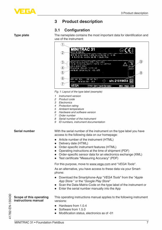
3.1 ConfigurationThenameplatecontainsthemostimportantdataforidentificationanduse of the instrument:
2
1
99
45
3
6
7
8
Fig. 1: Layout of the type label (example)1 Instrument version2 Product code3 Electronics4 Protection rating5 Ambient temperature6 Hardware and software version7 Order number8 Serial number of the instrument9 ID numbers, instrument documentation
With the serial number of the instrument on the type label you have accesstothefollowingdataonourhomepage:
• Article number of the instrument (HTML)• Delivery date (HTML)• Order-specificinstrumentfeatures(HTML)• Operating instructions at the time of shipment (PDF)• Order-specificsensordataforanelectronicsexchange(XML)• Testcertificate"MeasuringAccuracy"(PDF)For this purpose, move to www.vega.com and "VEGA Tools".As an alternative, you have access to these data via your Smart-phone:
• DownloadtheSmartphone-App"VEGA Tools" from the "Apple App Store " or the "Google Play Store"
• Scan the Data-Matrix-Code on the type label of the instrument or• Enter the serial number manually into the App
Thisoperatinginstructionsmanualappliestothefollowinginstrumentversions:
• Hardwarefrom1.0.4• Softwarefrom1.5.0• Modificationstatus,electronicsasof-01
Type plate
Serial number
Scope of this operating instructions manual

8
3 Product description
MINITRAC 31 • Foundation Fieldbus
41782-EN-130430
Theinstrumentisavailableindifferentelectronicsversions.Eachver-sioncanbeidentifiedviatheproductcodeonthetypelabel:
• Standard electronics type PT30E-XX
The scope of delivery encompasses:
• Radiation-based sensor• Documentation
– this operating instructions manual – Operating instructions manual "Display and adjustment mod-
ule" (optional) – Ex-specific"Safety instructions"(withExversions) – ifnecessary,furthercertificates
3.2 Principle of operationTheinstrumentissuitableforapplicationsinliquidsandbulksolidsinvesselsunderdifficultprocessconditions.Thereareapplicationpos-sibilities in nearly all areas of industry.The measured value is detected contactlessly right through the vessel wall.Neitheraprocessfittingnoravesselopeningarerequired.Theinstrument is thus ideal for retro installation.Theinstrumentcanbeusedformanydifferentmeasuringtasks.Apartfrom the main applications such as density measurement and level detection, the MINITRAC 31 can also detect residues and the mass flowrateinconjunctionwithaflowmeter.
Electronics versions
Scope of delivery
Application area

9
3 Product description
MINITRAC 31 • Foundation Fieldbus
4178
2-EN
-130
430
1 2
3
4
Fig. 2: MINITRAC 31 - Application possibilities1 Level measurement - Residue detection2 Point level detection3 Density measurement4 Massflowmeasurement
Further application possibilities are also the use as X-ray alarm or real value correction.If X-ray alarm is selected, the instrument detects radiation from exter-nal sources. Possible external radiation sources can be, for example, aweldjointtestinaneighbouringfacilityorotherradiation-basedinstruments.When the instrument operates as real value correction it transmits the real value to correct another radiation-based sensor. The measure-ment can thus be adapted perfectly to the situation in the vessel.
In radiation-based measurement, a Caesium-137 or Cobalt-60 iso-topeemitsfocussedgammaraysthatareattenuatedwhenpenetrat-ingthetubewallandthemedium.TheNaIdetectorontheoppositeside, on a pipeline for example, receives the radiation. The intensity of the radiation is dependent on the density of the measured media. The measuring principle has proven to be very reliable in conjunction withextremeprocessconditionsbecauseitmeasurescontactlesslyfromoutsidethroughthetubewall.Themeasuringsystemensures
Functional principle

10
3 Product description
MINITRAC 31 • Foundation Fieldbus
41782-EN-130430
maximum safety, reliability and plant availability independent of the medium and its properties.
3.3 Packaging, transport and storageYourinstrumentwasprotectedbypackagingduringtransport.Itscapacity to handle normal loads during transport is assured by a test based on ISO 4180.The packaging of standard instruments consists of environment-friendly, recyclable cardboard. For special versions, PE foam or PE foil is also used. Dispose of the packaging material via specialised recycling companies.
Transport must be carried out under consideration of the notes on the transport packaging. Nonobservance of these instructions can cause damage to the device.
The delivery must be checked for completeness and possible transit damage immediately at receipt. Ascertained transit damage or con-cealeddefectsmustbeappropriatelydealtwith.
Up to the time of installation, the packages must be left closed and stored according to the orientation and storage markings on the outside.Unlessotherwiseindicated,thepackagesmustbestoredonlyunderthefollowingconditions:
• Not in the open• Dry and dust free• Not exposed to corrosive media• Protected against solar radiation• Avoiding mechanical shock and vibration
• Storage and transport temperature see chapter "Supplement - Technical data - Ambient conditions"
• Relative humidity 20 … 85 %
3.4 Accessories and replacement partsThe display and adjustment module PLICSCOM is used for measured value indication, adjustment and diagnosis. It can be inserted into the sensor or the external display and adjustment unit and removed at any time.Youcanfindfurtherinformationintheoperatinginstructions"Display and adjustment module PLICSCOM" (Document-ID 27835).
TheinterfaceadapterVEGACONNECTenablestheconnectionofcommunication-capable instruments to the USB interface of a PC. For parameteradjustmentoftheseinstruments,anadjustmentsoftwaresuchasPACTwarewithVEGA-DTMisrequired.Youcanfindfurtherinformationintheoperatinginstructions"Interface adapter VEGACONNECT" (Document-ID 32628).
Packaging
Transport
Transport inspection
Storage
Storage and transport temperature
PLICSCOM
VEGACONNECT

11
3 Product description
MINITRAC 31 • Foundation Fieldbus
4178
2-EN
-130
430
VEGADIS81isanexternaldisplayandadjustmentunitforsensorswithsingleordoublechamberhousing.For the double chamber housing there is also an interface adapter for VEGADIS81required.Youcanfindfurtherinformationintheoperatinginstructions"VE-GADIS 81" (Document-ID 43814).
The electronics module PT30E.XX is a replacement part for radiation-based sensors MINITRAC 31.TheelectronicsmodulecanonlybeexchangedbyVEGAservicetechnician.
3.5 Corresponding source containerAradioactiveisotopeinasuitablesourceholderistheprerequisitefora radiation-based measurement setup.Thehandlingofradioactivematerialisregulatedbylaw.Theradiationprotectionrulesofthecountryinwhichthesystemisoperatedapplyfirstandforemost.In Germany, for example, the current radiation protection ordinance (StrlSchV)basedontheAtomicEnergyLaw(AtG)applies.Thefollowingpointsareimportantformeasurementwithradiation-based methods:
Ahandlingpermitisrequiredforoperationofasystemusinggammarays.Thispermitisissuedbytherespectivegovernmentofficeortheresponsibleauthority(inGermany,forexample,officesforenviron-mental protection, trade supervisory boards, etc.)Youcanfindfurtherinstructionsintheoperatinginstructionsmanualof the source container.
When handling a radioactive source, unnecessary radiation exposure must be avoided. An unavoidable radiation exposure must be kept as lowaspossible.Takenoteofthefollowingthreeimportantmeasures:
1 2 3
Fig. 3: Measures for protection against radioactive radiation1 Shielding2 Time3 Distance
Shielding-Providegoodshieldingbetweentheradioactivesourceandyourselfaswellasallotherpersons.Specialsourcecontainers
VEGADIS 81
Electronics module
Handling permit
General instructions for radiation protection

12
3 Product description
MINITRAC 31 • Foundation Fieldbus
41782-EN-130430
(e.g.VEGASOURCE)aswellasallmaterialswithhighdensity(e.g.lead,iron,concrete,etc.)provideeffectiveshielding.Time: Stay as short a time as possible in radiation exposed areas.Source: Your distance to the source should be as large as possible. The local dose rate of the radiation decreases in proportion to the squareofthedistancetotheradiationsource.
Theplantoperatormustappointaradiationsafetyofficerwiththenecessaryexpertknowledge.Heisresponsiblethattheradiationprotection ordinance is maintained and that all radiation protection measures are implemented.
Controlareasareareasinwhichthelocaldoserateexceedsacertainvalue.Onlypersonswhoundergoofficialdosemonitoringareallowedintothesecontrolareas.Youcanfindtherespectivelyvalidlimitvaluesfor control areas in the guideline of the respective authority (in Ger-many, for example, the radiation protection ordinance).We are at your disposal for further information concerning radiation protection and regulations in other countries.
Radiationsafetyofficer
Control area

13
4 Mounting
MINITRAC 31 • Foundation Fieldbus
4178
2-EN
-130
430
4 Mounting
4.1 General instructionsThe source container is part of the measuring system. In case the sourcecontainerisalreadyequippedwithanactiveisotope,thesource container must be locked before mounting.
Danger:Before mounting; make sure that the source is securely closed. Use a padlock to secure the source container in the closed condition and prevent it from being inadvertently opened.
Protectyourinstrumentthroughthefollowingmeasuresagainstmoisture penetration:
• Use the recommended cable (see chapter "Connecting to power supply")
• Tighten the cable gland• LooptheconnectioncabledownwardinfrontofthecableglandThis applies particularly to:
• outdoor mounting• installationsinareaswherehighhumidityisexpected(e.g.through
cleaning processes)• installations on cooled or heated vessels
Make sure that all parts of the instrument exposed to the process are suitable for the existing process conditions.These are mainly:
• Active measuring component• Processfitting• Process seal
Process conditions are particularly:
• Process pressure• Process temperature• Chemical properties of the medium• AbrasionandmechanicalinfluencesYoucanfindthespecificationsinchapter"Technical data" and on the nameplate.
Inthecaseofinstrumenthousingswithself-sealingNPTthreads,itisnotpossibletohavethecableentriesscrewedinatthefactory.Theopeningsforthecableglandsarethereforecoveredwithredprotec-tive caps as transport protection.Priortosetupyouhavetoreplacetheseprotectivecapswithap-provedcableglandsorclosetheopeningswithsuitableblindplugs.Thesuitablecableglandsandblindplugscomewiththeinstrument.
Switchoffsource
Protection against mois-ture
Suitability for the process conditions
Protective caps

14
4 Mounting
MINITRAC 31 • Foundation Fieldbus
41782-EN-130430
4.2 Mounting instructionsNote:Duringtheplanningstage,ourspecialistswillanalysetheconditionsof the measuring point and dimension the source (isotope) accord-ingly.Yougeta"SourceSizing"documentspecifyingtherequiredsourceactivity and containing all relevant mounting information for your measuring point.Youmustfollowtheinstructionsofthis"SourceSizing"documentinadditiontothefollowingmountinginstructions.Thefollowingmountinginformationisapplicableaslongasthereisnothingelsespecifiedinthe"SourceSizing"document.Youcanfindinformationonprotectivebarriersandthemountingof the corresponding source container in the operating instructions manualofthesourcecontainer,e.g.VEGASOURCE.You can mount the MINITRAC 31 in any position. If you have ordered yourinstrumentwithaleadcoverasaprotectionagainstambientradiation (optionally), the the sensor is shielded laterally against X-ray radiation. In this case, the radiation can only penetrate frontally.Fastenthesensorsinsuchawaythattheycannotfalloutoftheholder.Direct the exit angle of the source container to the MINITRAC 31.Mount the source container as close as possible to the vessel. If there aregaps,securetheareawithasafetyfenceandprotectivegratingso that no one can reach into the dangerous area.
Caution:Makesurethatthetubeisalwayscompletelyfilled.Mainlyinhorizon-tally arranged tube measuring distances, air bubbles or buildup in thetubecaninfluencethemeasuringresult.Measurementshouldbepreferably through the centre of the tube.
1
2
Fig. 4: Installation on a horizontal pipeline1 Air bubbles2 Buildup
Installation position

15
4 Mounting
MINITRAC 31 • Foundation Fieldbus
4178
2-EN
-130
430
Density measurementA density and concentration measurement is possible on pipelines and vessels. The accuracy of the measurement increases in propor-tion to the radiated length (L) of medium. This is particularly important inthecaseofproductswithlowdensityorsmalltubediameters.Therearedifferentwaystoincreasetheradiatedlength(L)ofthemedium.
L
L
L
1
4
a
b
2
3
Fig. 5: Installation possibilities - Density measurement or concentration meas-urement1a Direct radiation - Horizontal mounting1b Direct radiation - Vertical mouting or when the lead cover is used as protec-
tion against ambient radiation2 Inclined radiation for extention of the radiated length (L)3 Extension of the radiated length (L) by adding a tube angle piece as meas-
uring distance4 Integrated lead cover as protection against ambient radiation - the instru-
ment is hence shielded laterally

16
4 Mounting
MINITRAC 31 • Foundation Fieldbus
41782-EN-130430
Withdensitymeasurement,theradiationdifferencewithdifferingdensityisverylow.Especiallywithsmalltubediameters,thechangeis negligible.Therefore it is important to shield from interfering X-ray radiation. To protecttheinstrumentagainstX-rayradiation,itcanbebeequippedwithanoptionalleadring.Alaterretrofittingoftheleadringisnotpossible.
MassflowrateThemassflowratecanbedeterminedwiththeMINITRAC31inconjunctionwithaflowmeter.
1
2
Fig.6:Massflowratemeasurement1 Flow meter2 MINITRAC 31
Point level detectionForleveldetection,thesensorisgenerallymountedhorizontallyattheheightoftherequestedlimitlevel.Makesurethattherearenostrutsor reinforcements at this position in the vessel.Directtheexitbeamofthesourcecontainerexactlytowardsthemeasuring range of MINITRAC 31.

17
4 Mounting
MINITRAC 31 • Foundation Fieldbus
4178
2-EN
-130
430
3
2
1
Fig. 7: Mounting position - level detection1 Mounting horizontal2 Mounting vertical3 Mounting horizontally, at right angles to container
Level measurement - Residue detectionThe MINITRAC 31 can be used for residue detection, e.g. in storage tanksforhigh-costliquids.Forthispurpose,theinstrumentmustbemountedatthelowestpointofthevessel.

18
4 Mounting
MINITRAC 31 • Foundation Fieldbus
41782-EN-130430
Fig. 8: Level measurement - Residue detection on a storage tank
If the max. ambient temperature is exceeded, you must take suitable measures to protect the instrument against overheating.You can protect the instrument by providing a suitable insulation againsttheheatormountingtheinstrumentfurtherawayfromtheheat source.Make sure these measures are taken into account already in the plan-ningstage.Ifyouwanttocarryoutsuchmeasureslateron,contactour specialists to ensure that the accuracy of the application is not impaired.Ifthesemeasuresarenotsufficienttomaintainthemax.ambienttemperature,youcouldconsiderusingthewatercoolingsystemweofferforMINITRAC31.Thewatercoolingmustalsobeincludedinthecalculationsforthemeasuring point. Contact our specialists regarding the dimensioning ofthewatercooling.
Protection against heat

19
5Connectingtopowersupply
MINITRAC 31 • Foundation Fieldbus
4178
2-EN
-130
430
5 Connecting to power supply
5.1 Preparing the connectionAlwayskeepinmindthefollowingsafetyinstructions:
• Connect only in the complete absence of line voltage• If overvoltage surges are expected, overvoltage arresters should
be installed
Theinstrumentrequiresaoperatingvoltageof9…32VDC.Operat-ingvoltageandthedigitalbussignalarecarriedonthesametwo-wireconnectioncable.PowerissuppliedviatheH1powersupply.
ConnectioniscarriedoutwithscreenedcableaccordingtoFieldbusspecification.Usecablewithroundcross-section.Acableouterdiameterof5…9mm(0.2…0.35in)ensuresthesealeffectofthecablegland.Ifyouareusingcablewithadifferentdiameterorcross-section,exchange the seal or use a suitable cable gland.Make sure that the entire installation is carried out according to the Fieldbusspecification.Inparticular,makesurethatthebusistermi-natedwithsuitableterminatingresistors.
Generallyprovideallunusedcableentrieswithsuitableblindplugs.Thethinfoamrubberwahsersinthecableglandsareonlyusedasdust cover during trasport.
Inthecaseofinstrumenthousingswithself-sealingNPTthreads,itisgenerallynotpossibletohavethecableglandsscrewedinatthefactory.Theopeningsforthecableglandsarethereforecoveredwithred protective caps as transport protection.Youhavetoreplacetheseprotectivecapswithapprovedcableglandsbeforesetuporcoverthemwithsuitablefillerplugs.Unusedcableglandsdonotprovidesufficientprotectionagainstmoistureandmustbereplacedwithfillerplugs.Thesuitablecableglandsandblindplugscomewiththeinstrument.
Make sure that the cable screening and ground is executed accord-ingtotheFielbusspecification.IfelectromagneticinterferenceisexpectedwhichisabovethetestvaluesofEN61326-1forindustrialareas,werecommendtoconnectthecablescreenonbothendstoground potential.Withsystemswithpotentialequalisation,connectthecablescreendirectlytogroundpotentialatthepowersupplyunit,intheconnectionbox and at the sensor. The screen in the sensor must be connected directly to the internal ground terminal. The ground terminal outside onthehousingmustbeconnectedtothepotentialequalisation(lowimpedance).Insystemswithoutpotentialequalisationwithcablescreeningonboth sides, connect the cable screen directly to ground potential at
Safety instructions
Voltage supply
Connection cable
Cable entry
Cable gland ½ NPT
Cable screening and grounding

20
5Connectingtopowersupply
MINITRAC 31 • Foundation Fieldbus
41782-EN-130430
thepowersupplyunitandatthesensor.IntheconnectionboxorT-distributor, the screen of the short stub to the sensor must not be connected to ground potential or to another cable screen. The cable screenstothepowersupplyunitandtothenextdistributormustbeconnected to each other and also connected to ground potential via a ceramiccapacitor(e.g.1nF,1500V).Low-frequencypotentialequali-sationcurrentsarethussuppressed,buttheprotectiveeffectagainsthighfrequencyinterferencesignalsremains.
The voltage supply and signal output are connected via the spring-loaded terminals in the housing.The connection to the display and adjustment module or to the inter-face adapter is carried out via contact pins in the housing.
Proceedasfollows:Theprocedureappliestoinstrumentswithoutexplosionprotection.1. Unscrewthebighousingcover2. Loosen compression nut of the cable entry3. Remove approx. 10 cm (4 in) of the cable mantle, strip approx.
1cm(0.4in)ofinsulationfromtheendsoftheindividualwires4. Insert the cable into the sensor through the cable entry
1
Fig. 9: Connection steps 4 and 51 Locking of the terminal blocks
5. Insertasmallslottedscrewdriverfirmlyintotherectangularlockopenings of the respective connection terminal
Connection technology
Connection procedure

21
5Connectingtopowersupply
MINITRAC 31 • Foundation Fieldbus
4178
2-EN
-130
430
6. Insertthewireendsintotheroundopeningsoftheterminalsac-cordingtothewiringplan
Information:Solidcoresaswellasflexiblecoreswithcableendsleevesareinserteddirectlyintotheterminalopenings.Incaseofflexiblecoreswithoutendsleeves,presstherectangularlockopeningwithasmallscrewdriver;theterminalopeningisfreed.Whenthescrewdriverisreleased, the terminal opening closes again.7. Checktheholdofthewiresintheterminalsbylightlypullingon
themToloosenaline,insertasmallslottedscrewdriverfirmlyintotherectangular locking opening according to the illustration
8. Connect the screen to the internal ground terminal, connect the outergroundterminaltopotentialequalisation
9. Tighten the compression nut of the cable entry. The seal ring must completely encircle the cable
10. ScrewthehousingcoverbackonTheelectricalconnectionishencefinished.
Information:The terminal blocks are pluggable and can be detached from the electronics.Forthispurposeloosenthetwolaterallockingleversoftheterminalblockwithasmallscrewdriver.Whenlooseningthelock-ing,theterminalblockisautomaticallysqueezedout.Itmustsnapinplacewhenre-inserted.

22
5Connectingtopowersupply
MINITRAC 31 • Foundation Fieldbus
41782-EN-130430
5.2 Connection-Density,massflowratemeasurement
Non-Ex instruments and instruments with non-intrinsically safe current output
1 1
24
/L
/N
PE
56
2211 12
2122
1920
1817
1413
1615
12
2
6
1
43
5
7
8
910
Fig. 10: Electronics and connection compartment with non-Ex instruments and instruments with non-intrinsically safe current output1 Voltage supply2 Relay output3 Signal output FF bus4 Signal input 4 … 20 mA (active sensor)5 Switching input for NPN transistor6 Switchinginputfloating7 Transistor output8 Interface for sensor-sensor communication (MGC)9 Simulation switch (1 = simulation on)10 Setting the bus address for sensor-sensor communication (MGC)1)
5 6 7 8
2
1
Fig. 11: Adjustment and connection compartment with non-Ex instruments and instruments with non-intrinsically safe current output1 Terminals for the external display and adjustment unit2 Contact pins for the display and adjustment module or interface adapter
Instruments with intrinsically safe current outputYoucanfinddetailedinformationontheexplosion-protectedversions(Ex-ia,Ex-d)intheEx-specificsafetyinstructions.Thesesafety
Electronics and con-nection compartment - Non-Ex instruments and instruments with non-intrinsically safe current output
Adjustment and con-nection compartment - Non-Ex instruments and instruments with non-intrinsically safe current output
1) MGC = Multi Gauge Communication

23
5Connectingtopowersupply
MINITRAC 31 • Foundation Fieldbus
4178
2-EN
-130
430
instructionsarepartofthescopeofdeliveryandcomewiththeEx-approved instruments.
1 1
24
/L
/N
PE
56
2211 12
2122
1920
1817
1413
1615
12
2
5
1
3
4
6
7
89
Fig. 12: Electronics and connection compartment (Ex-d) with instruments with intrinsically safe current output1 Voltage supply2 Relay output3 Signal input 4 … 20 mA (active sensor)4 Switching input for NPN transistor5 Switchinginputfloating6 Transistor output7 Interface for sensor-sensor communication (MGC)8 Simulation switch (1 = simulation on)9 Setting the bus address for sensor-sensor communication (MGC)2)
5 6 7 8
2
3
4
1 2+( ) (-)
1
Fig. 13: Adjustment and connection compartment (Ex-ia) with instruments with intrinsically safe current output1 Terminals for intrinsically safe signal output FF bus2 Contact pins for the display and adjustment module or interface adapter3 Terminals for the external display and adjustment unit4 Ground terminal
Electronics and connec-tion compartment - In-struments with intrinsi-cally safe current output
Adjustment and connec-tion compartment - In-struments with intrinsi-cally safe current output
2) MGC = Multi Gauge Communication

24
5Connectingtopowersupply
MINITRAC 31 • Foundation Fieldbus
41782-EN-130430
5.3 Connection - Level detectionNon-Ex instruments and instruments with non-intrinsically safe current output
1 1
24
/L
/N
PE
56
2211 12
2122
1920
1817
1413
1615
12
2
6
1
43
5
7
8
910
Fig. 14: Electronics and connection compartment with non-Ex instruments and instruments with non-intrinsically safe current output1 Voltage supply2 Relay output3 Signal output FF bus4 Signal input 4 … 20 mA (active sensor)5 Switching input for NPN transistor6 Switchinginputfloating7 Transistor output8 Interface for sensor-sensor communication (MGC)9 Simulation switch (1 = simulation on)10 Setting the bus address for sensor-sensor communication (MGC)3)
5 6 7 8
2
1
Fig. 15: Adjustment and connection compartment with non-Ex instruments and instruments with non-intrinsically safe current output1 Terminals for the external display and adjustment unit2 Contact pins for the display and adjustment module or interface adapter
Instruments with intrinsically safe current outputYoucanfinddetailedinformationontheexplosion-protectedversions(Ex-ia,Ex-d)intheEx-specificsafetyinstructions.ThesesafetyinstructionsarepartofthescopeofdeliveryandcomewiththeEx-approved instruments.
Electronics and con-nection compartment - Non-Ex instruments and instruments with non-intrinsically safe current output
Adjustment and con-nection compartment - Non-Ex instruments and instruments with non-intrinsically safe current output
3) MGC = Multi Gauge Communication

25
5Connectingtopowersupply
MINITRAC 31 • Foundation Fieldbus
4178
2-EN
-130
430
1 1
24
/L
/N
PE
56
2211 12
2122
1920
1817
1413
1615
122
5
1
3
4
6
7
89
Fig. 16: Electronics and connection compartment (Ex-d) with instruments with intrinsically safe current output1 Voltage supply2 Relay output3 Signal input 4 … 20 mA (active sensor)4 Switching input for NPN transistor5 Switchinginputfloating6 Transistor output7 Interface for sensor-sensor communication (MGC)8 Simulation switch (1 = simulation on)9 Setting the bus address for sensor-sensor communication (MGC)4)
5 6 7 8
2
3
4
1 2+( ) (-)
1
Fig. 17: Adjustment and connection compartment (Ex-ia) with instruments with intrinsically safe current output1 Terminals for intrinsically safe signal output FF bus2 Contact pins for the display and adjustment module or interface adapter3 Terminals for the external display and adjustment unit4 Ground terminal
Electronics and connec-tion compartment - In-struments with intrinsi-cally safe current output
Adjustment and connec-tion compartment - In-struments with intrinsi-cally safe current output
4) MGC = Multi Gauge Communication

26
6Setupwiththedisplayandadjustmentmodule
MINITRAC 31 • Foundation Fieldbus
41782-EN-130430
6 Set up with the display and adjustment module
6.1 Insert display and adjustment moduleThe display and adjustment module can be inserted into the sensor and removed again at any time. It is not necessary to interrupt the powersupply.Proceedasfollows:1. Unscrewthesmallhousingcover2. Place the display and adjustment module in the desired position
ontheelectronics(youcanchooseanyoneoffourdifferentposi-tions - each displaced by 90°)
3. Press the display and adjustment module onto the electronics and turn it to the right until it snaps in.
4. ScrewhousingcoverwithinspectionwindowtightlybackonRemoval is carried out in reverse order.Thedisplayandadjustmentmoduleispoweredbythesensor,anad-ditional connection is not necessary.
12
Fig. 18: Insert display and adjustment module
Note:Ifyouintendtoretrofittheinstrumentwithadisplayandadjustmentmoduleforcontinuousmeasuredvalueindication,ahighercoverwithaninspectionglassisrequired.
Mount/Dismount display and adjustment module

27
6Setupwiththedisplayandadjustmentmodule
MINITRAC 31 • Foundation Fieldbus
4178
2-EN
-130
430
6.2 Adjustment system
1
2
Fig. 19: Display and adjustment elements1 LC display2 Adjustment keys
• [OK] key: – Movetothemenuoverview – Confirmselectedmenu – Edit parameter – Save value
• [->] key: – Presentation, change measured value – Select list entry – Select editing position
• [+] key: – Change value of the parameter
• [ESC] key: – Interrupt input – Jump to next higher menu
The sensor is adjusted via the four keys of the display and adjust-ment module. The LC display indicates the individual menu items. The functionsoftheindividualkeysareshownintheaboveillustration.Approx. 60 minutes after the last pressing of a key, an automatic reset tomeasuredvalueindicationistriggered.Anyvaluesnotconfirmedwith[OK]willnotbesaved.
6.3 Parameter adjustment - Level measurementThrough the parameter adjustment the instrument is adapted to the application conditions. The parameter adjustment is carried out via an adjustment menu.
Key functions
Adjustment system

28
6Setupwiththedisplayandadjustmentmodule
MINITRAC 31 • Foundation Fieldbus
41782-EN-130430
Information:Inthisoperatinginstructionsmanual,theinstrument-specificparam-eters are described. Further general parameters are described in the operating instructions manual "Display and adjustment module".
Caution:Duringthefirstsetuporafteraninstrumentresettheinstrumentstartswithpresetstandardvalues.Thesevaluearenotsuitableforyourap-plication and must be replaced by real values.Carryoutasetupinthesequencedescribedinthefollowing.
Themainmenuisdividedintofivesectionswiththefollowingfunc-tions:
Setup: Settings, e.g. for measurement loop name, isotope, applica-tion, background radiation, adjustment, signal outputDisplay: Settings, for example language, measured value displayDiagnosis: Information, for example, of device status, peak value, simulationAdditional adjustments: Instrument unit, reset, date/time, copying functionInfo:Instrumentname,hardwareandsoftwareversion,dateofmanu-facture, instrument features
Check if the correct language is already set for the display. If not, you can change the language in the menu item "Display/Language".
StartwiththesetupofMINITRAC31.In the main menu point "Setup", the individual submenu points should beselectedsubsequentlyandprovidedwiththecorrectparametersto ensure the optimum adjustment of the measurement. The proce-dureisdescribedinthefollowing.Possiblykeepthesequenceofthemenuitems.
Adjustment
In this menu item you can adjust the MINITRAC 31 to the integrated isotope in the source container.Forthispurpose,checkwhichisotopeisintegratedinthesourcecontainer.Youcanfindthisinformationonthetypelabelofthesourcecontainer.
Enter here, the respective application.
Instrument start
Main menu
Proceeding
Setup/Isotope
Setup - Application

29
6Setupwiththedisplayandadjustmentmodule
MINITRAC 31 • Foundation Fieldbus
4178
2-EN
-130
430
Thismenuitemenablesadaptationofthesensortotherequestedap-plication.Youcanchoosebetweenthefollowingapplications:"Level", "Density", "Limit level", "X-ray alarm" or "Real value correction".
Thenaturalradiationonearthinfluencestheaccuracyofthemeas-urement.With this menu item the natural background radiation can be faded out.For this purpose, the MINITRAC 31 measures the natural background radiationandsetsthepulseratetozero.Inthefuture,thepulseratefromthisbackgroundradiationwillbeautomatically deducted from the total pulse rate. This means: only thecomponentofthepulserateoriginatingfromthesourcewillbedisplayed.The source container must be closed for this setting.
In this menu item you can select the units of the process value and the temperature.
In this menu item you can enter the measuring range (min. and max. process value) of the sensor.Thesesettingsinfluencethecurrentoutputofthesensor.Enterinthemenuwindow"Max. process value" the max. level (full), for example in "m". This corresponds to an output current of 20 mA.Enterinthemenuwindow"Min. process value" the min. level (empty), for example in "m". This corresponds to an output current of 4 mA.
In this menu item you can carry out the adjustment of the sensor.Duetothemeasuringprinciple,thereisnolinearrelationshipbetweenpulserateandlevel.Hence,thisadjustment(i.e.linearization)mustinany case be carried out.
Note:Ifyoucannotfillthevesselwiththeoriginalmedium,itisalsopossibletocarryouttheadjustmentwithwater.Prerequisites:Theradiationisswitchedon-sourcecontainerissetto"On"Thevesseliseithercompletelyfilled(100%)orcompletelyemptied(0 %).Dependingonthefactifthevesselisfilledoremptied,youcancar-riedoutfirstthefullortheemptyadjustment.TheMINITRAC31sortsthe points automatically according to their level.Select "Show table"todisplayandeditthelinearizationpoints.Select "Linearization - New"toenterthefirstpoint.Select "Determine count rate"toenterthefirstpoint.The determination of the actual count rate lasts 2 minutes. After the count rate has been determined, you can accept the value (ct/s).Enternowthecorrespondinglevel(m).
Setup/Background radia-tion
Setup - Units
Setup - Adjustment
Setup - Linearization

30
6Setupwiththedisplayandadjustmentmodule
MINITRAC 31 • Foundation Fieldbus
41782-EN-130430
By doing so, you assign a respective level to the actual count rate.
Acceptthevaluepairwith"OK".Dependingifyouhavestartedwithfulloremptyvessel,youhavetocontinueemptyingorfillingthevessel.Alsocarryoutsuchalinearizationwithseveraldifferentfillingheightsif you have a linear vessel.Amaximumof32linearizationpointsispossible.
In this menu item you can adjust the damping of the sensor. With ityoucansuppressfluctuationsinthemeasuredvalueindication,causede.g.byanagitatedproductsurface.Thistimecanbebetween1 and 1200 seconds. Keep in mind that also the reaction time in-creasesandtheinstrumentreactstoquicklevelchangeswithadelay.Generallyatimeofapproximately60secondsissufficienttosmooththe measured value indication.
Radiationfromexternalsourcescaninfluencethemeasuringresultofthe sensor.Possibleexternalradiationsourcescanbe,forexample,aweldjointtest on a neighbouring facility or other radiation-based instruments.An X-ray alarm is triggered if the impulses (ct/s) are more than 25 % abovethemax.valuefromthelinearizationtable.This fault message is only outputted for the period of the increased X-ray radiation. Then the fault message is automatically reset.In this menu item you can determine the behaviour of the sensor whenexternalradiationsourcesappear.
In this menu item you can activate the relay output and determine its functionaswellastheswitchingpoints.When the output of the process values is set, you can choose be-tweenoverfillanddryrunprotection.The relay outputs of the sensor react accordingly.You can choose "no" reference value. In this case, the relay output operates as fail safe relay.
Caution:Independentoftheselectedreferencevalue,therelaywilldeenergizein case of failure.
Additional settings
Whenaresetiscarriedout,allsettings(withonlyafewexceptions)are reset. The exceptions are: PIN, language and SIL.
Setup - Damping
Setup/External radiation alarm
Setup/Relay
Additional adjustments - Reset

31
6Setupwiththedisplayandadjustmentmodule
MINITRAC 31 • Foundation Fieldbus
4178
2-EN
-130
430
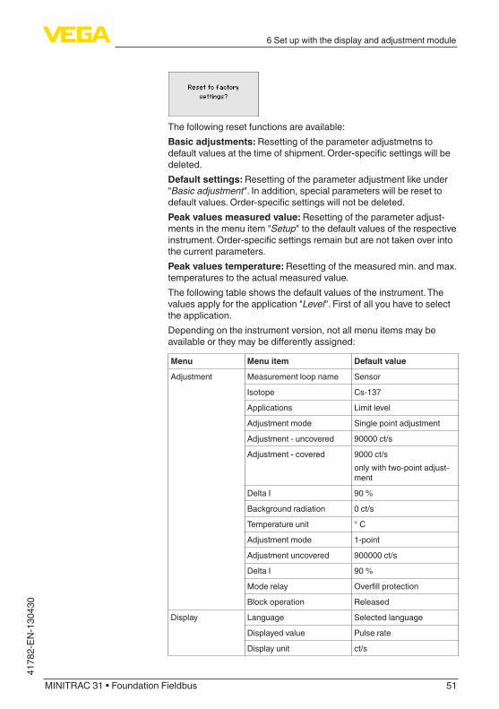
Thefollowingresetfunctionsareavailable:Basic adjustments: Resetting of the parameter adjustmetns to defaultvaluesatthetimeofshipment.Order-specificsettingswillbedeleted.Default settings: Resetting of the parameter adjustment like under "Basic adjustment".Inaddition,specialparameterswillberesettodefaultvalues.Order-specificsettingswillnotbedeleted.Peak values measured value: Resetting of the parameter adjust-ments in the menu item "Setup" to the default values of the respective instrument.Order-specificsettingsremainbutarenottakenoverintothe current parameters.Peak values temperature: Resetting of the measured min. and max. temperatures to the actual measured value.Thefollowingtableshowsthedefaultvaluesoftheinstrument.Thevalues apply for the application "Level". First of all you have to select the application.Depending on the instrument version, not all menu items may be availableortheymaybedifferentlyassigned:

32
6Setupwiththedisplayandadjustmentmodule
MINITRAC 31 • Foundation Fieldbus
41782-EN-130430
Menu Menu item Default value
Adjustment Measurement loop name Sensor
Isotope Cs-137
Applications Level
Background radiation 0 ct/s
Unit of the process value %
Temperature unit ° C
Adjustment min. Min. process value = 0 %
Adjustment max. Max. process value = 100 %
Linearization 0 ct/s = 100 %
90000 ct/s = 0 %
Damping 60 s
Real value correction 0
Mode Overfillprotection
Upperswitchingpoint-Pro-cess value
0 %
Lowerswitchingpoint-Pro-cess value
0 %
Upperswitchingpoint-Tem-perature
50 °C
Upperswitchingpoint-Tem-perature
25 °C
Reference value - Relay None
Block operation Released
Address - Summation Slave free
Display Language Selected language
Displayed value Pulse rate
Display unit ct/s
Additional set-tings
Temperature unit °C
Linearizationcurve Empty
HART mode StandardAddress 0
6.4 Parameter adjustment - Density measurement
Through the parameter adjustment the instrument is adapted to the application conditions. The parameter adjustment is carried out via an adjustment menu.
Information:Inthisoperatinginstructionsmanual,theinstrument-specificparam-eters are described. Further general parameters are described in the operating instructions manual "Display and adjustment module".

33
6Setupwiththedisplayandadjustmentmodule
MINITRAC 31 • Foundation Fieldbus
4178
2-EN
-130
430
PrerequisitesThefollowingrequirementsmustbefulfilledforreliableandsafeoperation:
• Thetubemustbefilled.Theremustbenoairbubblesinthetube• Thesourcecontainerisswitchedon• A sample point is close to the measuring point
Warning:Whenthesourcecontainerisswitchedon,thetubemustalwaysbefilled.Ifthetubeisempty,therecanbeanincreasedlocaldoserate.Makesurethatthetubeisfilledevenincaseofplantdowntime,orswitchthesourcecontaineroff.
Carryoutasetupinthesequencedescribedinthefollowing.
Caution:Duringthefirstsetuporafteraninstrumentresettheinstrumentstartswithpresetstandardvalues.Thesevaluearenotsuitableforyourap-plication and must be replaced by real values.
Themainmenuisdividedintofivesectionswiththefollowingfunc-tions:
Setup: Settings, e.g. for measurement loop name, isotope, applica-tion, background radiation, adjustment, signal outputDisplay: Settings, for example language, measured value displayDiagnosis: Information, for example, of device status, peak value, simulationAdditional adjustments: Instrument unit, reset, date/time, copying functionInfo:Instrumentname,hardwareandsoftwareversion,dateofmanu-facture, instrument features
Check if the correct language is already set for the display. If not, you can change the language in the menu item "Display/Language".
StartwiththesetupofMINITRAC31.In the main menu point "Setup", the individual submenu points should beselectedsubsequentlyandprovidedwiththecorrectparametersto ensure the optimum adjustment of the measurement. The proce-dureisdescribedinthefollowing.Possiblykeepthesequenceofthemenuitems.
Instrument start
Main menu
Proceeding

34
6Setupwiththedisplayandadjustmentmodule
MINITRAC 31 • Foundation Fieldbus
41782-EN-130430
Adjustment
In this menu item you can adjust the MINITRAC 31 to the integrated isotope in the source container.Forthispurpose,checkwhichisotopeisintegratedinthesourcecontainer.Youcanfindthisinformationonthetypelabelofthesourcecontainer.
Through this selection, the sensitivity of the sensor is adapted perfectly to the isotope. The normal reduction of the emitter activity is hence considered through the radioactive decay.TheMINITRAC31requiresthisinformationoftheautomaticdecaycompensation. This ensures an interference-free measurement over the complete life time of the gamma emitter - an annual recalibration is not necessary.Entertherequestedparametersviatheappropriatekeys,saveyoursettingswith[OK]andjumptothenextmenuitemwiththe[ESC] and the [->] key.
Enter here, the respective application.Thismenuitemenablesadaptationofthesensortotherequestedap-plication.Youcanchoosebetweenthefollowingapplications:"Level", "Density", "Limit level", "X-ray alarm" or "Real value correction".
Thenaturalradiationonearthinfluencestheaccuracyofthemeas-urement.With this menu item the natural background radiation can be faded out.
Note:Make sure that some products have a self-radiation. This is for ex-amplethecasewithoilorpotashsaltlye.Thereforethetubemustbefilledtodeterminethebackgroundradiation.For this purpose, the MINITRAC 31 measures the natural background radiationandsetsthepulseratetozero.Inthefuture,thepulseratefromthisbackgroundradiationwillbeautomatically deducted from the total pulse rate. This means: only thecomponentofthepulserateoriginatingfromthesourcewillbedisplayed.The source container must be closed for this setting (OFF).
Setup/Isotope
Setup/Application
Setup/Background radia-tion

35
6Setupwiththedisplayandadjustmentmodule
MINITRAC 31 • Foundation Fieldbus
4178
2-EN
-130
430
In this menu item you can select the units of the process value and the temperature.
In this menu item you can enter the measuring range (min. and max. process value) of the sensor.Thesesettingsinfluencethecurrentoutputofthesensor.
Enterinthemenuwindow"Max. process value" the max. density value, for example in "g/cm3". This corresponds to an output current of 20 mA.
Enterinthemenuwindow"Min. process value" the min. density value, for example in "g/cm3". This corresponds to an output current of 4 mA.
In this menu item you can enter the inside diameter of the tube or the radiated length (L).Thissettinginfluencestheaccuracyofthesensor.
First of all, select the unit of the inside diameter.
Setup/Units
Setup/Adjustment
Setup/Inside diameter

36
6Setupwiththedisplayandadjustmentmodule
MINITRAC 31 • Foundation Fieldbus
41782-EN-130430
Enterinthemenuwindow"Inside diameter" the inside diamter of the tube, for example in "cm".Ifthetubeisnotradiatedwith90°,thenyouhavetoentertheradiatedlength (L) instead of the tube inside diameter.Enteralsoheretheradiatedlengthwithoutthewallthicknessofthetube.
L
Fig. 20: With inclined mounting, the radiated length of the tube is applicable
In this menu item you can carry out the adjustment of the sensor.
Caution:Duringthefirstsetuporafteraninstrumentreset,thelinearizationstands at the preset value pair (90000 ct/s and 0.500 g/cm3). These values are not suitable for your application and must be replaced by realvalues.Deletethisvaluepairinthefollowingprocedureandcarryoutthelinearization.Duetothemeasuringprinciple,thereisnolinearrelationshipbetweenpulserateanddensity.Hence,thisadjustment(i.e.linearization)mustbe carried out in any event.Carryoutthisadjustmentwithseveralpointstoincreasetheaccuracyof the measurement.
Setup/Linearization

37
6Setupwiththedisplayandadjustmentmodule
MINITRAC 31 • Foundation Fieldbus
4178
2-EN
-130
430
Note:Waterhasasaknowndensityvalueof1g/cm3. Carry out the adjust-mentwithwater,ifpossible.
• Prerequisites:Theradiationisswitchedon-sourcecontainerissetto"On"Thetubeiscompletelyfilled.Possiblegasbubblesorairinclusionscaninfluencethemeasurement.The MINITRAC 31 sorts the points automatically according to their density.
Select "Show table"todisplayandeditthelinearizationpoints.
Select "Linearization - New"toenterthefirstpoint.
Select "Determine count rate"toenterthefirstpoint.
The determination of the actual count rate lasts 2 minutes. After the countratewasdetermined,youcanacceptthevalue.The count rate is stated in ct/s. This is the number of counts per sec-ond, i.e. the measured radioactive radiation dose actually reaching the sensor.
Enternowthecorrespondingdensityvalue(g/cm3).You thus assign a corresponding density to the actual count rate.
Note:If possible, take a product sample and determine the density simulta-neously in your sampling position.Ithasprovenmarkingtheproductsmapleswithdateandrespec-tivecountrate.Hencethevaluescanbeassignedlateronwithoutproblems.

38
6Setupwiththedisplayandadjustmentmodule
MINITRAC 31 • Foundation Fieldbus
41782-EN-130430
Acceptthevaluepairwith"OK".Enterasmanylinearizationpointsaspossible.Youcaninfluencethe accuracy of the density measurement by doing this. The more linearizationpointsyouenterandthehigherthedifferencebetweenthe density values, the more reliable the measurement.Valuepairsthatarenotyetcomplete,e.g.duetoamissingdensitydetermination,canbeeditedlaterwiththefunction"Setup/Lineariza-tion" under the item "Change/Edit".Amaximumof32linearizationpointsispossible.
Note:If you cannot change the medium during the adjustment process, it ispossibletocarryoutthelinearizationwithonlyonepoint.However,youshouldenterfurtherlinearizationpointslater,ifpossible.
• ShowdiagramThismenuitemisonlyavailableifalinearizationwasalreadycarriedout.
• ShowtableInthismenuitemyoucanshowtheindividualvaluepairsofthelinearization.
• Linearization-DeleteYoucanalsodeleteindividuallinearizationpoints.Enterthenumberofthepointyouwanttodelete.
• Linearization-ModifyYoucanalsomodifyindividuallinearizationpoints.

39
6Setupwiththedisplayandadjustmentmodule
MINITRAC 31 • Foundation Fieldbus
4178
2-EN
-130
430
After editing, you have to activate the complete value pair so that the linearizationpointwillbeeffective.
Yourecognizeactivelinearizationpointsbyasmallsquarewithacrossnexttothenumberofthelinearizationpoint.
In this menu item you can adjust the damping of the sensor. With ityoucansuppressfluctuationsinthemeasuredvalueindication,causede.g.byanagitatedproductsurface.Thistimecanbebetween1 and 1200 seconds. Keep in mind that also the reaction time in-creasesandtheinstrumentreactstoquicklevelchangeswithadelay.Generallyatimeofapproximately60secondsissufficienttosmooththe measured value indication.With the setting "Automatic", the instrument itself calculates a suitable damping on the basis of the adjustment and the measured value changes.Thissettingisparticularlysuitableforapplicationwherefastandslowlevelchangesoccur.
The implementation of a real value corretion is only necessary if the requirementsofthemeasurementloophavechanged,forexamplewithabrasioninatube.Ifyouknowthedensityofacertainmedium,youcanenterthedeter-mined real density in this menu item to correct the measured value. Thefunctionshiftsthelinearizationcurvetothisdeterminedpoint.The measurement can thus be adapted exactly to the conditions in the tube.
In this menu item you can activate the relay output and determine its functionaswellastheswitchingpoints.
Setup/Damping
Setup/Real value correc-tion (manually)
Setup/Relay

40
6Setupwiththedisplayandadjustmentmodule
MINITRAC 31 • Foundation Fieldbus
41782-EN-130430
When the output of the process values is set, you can choose be-tweenoverfillanddryrunprotection.The relay outputs of the sensor react accordingly.Thefollowingreferencevaluescanbeselected:
• None - Relay operates as fail safe relay• Electronics temperature• Process value
"No" reference value means that the relay output operates as fail safe relay.
Example for the adjustment of the process value
Caution:Independentoftheselectedreferencevalue,therelaywilldeenergizein case of failure.
With this menu item you safeguard the sensor parameters against unauthorizedorunintentionalmodifications.This menu item is described in the operating instructions manual "Display and adjustment module".
Display
With this parameter you can change the display language.This parameter is described in the operating instructions manual "Display and adjustment module".
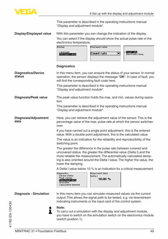
With this parameter you can change the indication of the display.Youcanchooseifthedisplayshouldshowtheactualpulserate,theelectronics temperature or the percentage value.
Lock setup/adjustment
Display/Language
Display/Displayed value
41
6Setupwiththedisplayandadjustmentmodule
MINITRAC 31 • Foundation Fieldbus
4178
2-EN
-130
430
Diagnostics
Inthismenuitem,youcanenquirethestatusofyoursensor.Innormaloperation, the sensor displays the message "OK". In case of fault, you willfindthecorrespondingfaultcodehere.This parameter is described in the operating instructions manual "Display and adjustment module".
The peak value function holds the max. and min. values during opera-tion.This parameter is described in the operating instructions manual "Display and adjustment module".
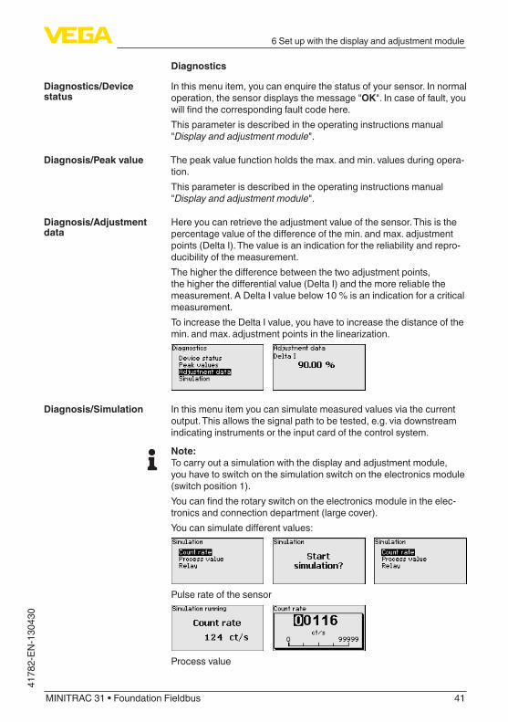
Here you can retrieve the adjustment value of the sensor. This is the percentagevalueofthedifferenceofthemin.andmax.adjustmentpoints (Delta I). The value is an indication for the reliability and repro-ducibility of the measurement.Thehigherthedifferencebetweenthetwoadjustmentpoints,thehigherthedifferentialvalue(DeltaI)andthemorereliablethemeasurement.ADeltaIvaluebelow10%isanindicationforacriticalmeasurement.To increase the Delta I value, you have to increase the distance of the min.andmax.adjustmentpointsinthelinearization.
In this menu item you can simulate measured values via the current output.Thisallowsthesignalpathtobetested,e.g.viadownstreamindicating instruments or the input card of the control system.
Note:Tocarryoutasimulationwiththedisplayandadjustmentmodule,youhavetoswitchonthesimulationswitchontheelectronicsmodule(switchposition1).Youcanfindtherotaryswitchontheelectronicsmoduleintheelec-tronics and connection department (large cover).Youcansimulatedifferentvalues:
Pulse rate of the sensor
Process value
Diagnostics/Device status
Diagnosis/Peak value
Diagnosis/Adjustment data
Diagnosis/Simulation

42
6Setupwiththedisplayandadjustmentmodule
MINITRAC 31 • Foundation Fieldbus
41782-EN-130430
Switchingfunctionoftherelay
Information:The simulation is automatically terminated 10 minutes after the last press of a key.
Additional settings
In this menu item, the PIN is permanently activated/deactivated. Thus youprotectthesensordataagainstunauthorizedaccessandunin-tended changes. The default setting of the PIN is 0000.This parameter is described in the operating instructions manual "Display and adjustment module".
In this menu item you can set the actual date and time.This parameter is described in the operating instructions manual "Display and adjustment module".
Whenaresetiscarriedout,allsettings(withonlyafewexceptions)are reset. The exceptions are: PIN, language, SIL and HART mode.
Thefollowingresetfunctionsareavailable:Basic adjustments: Resetting of the parameter adjustmetns to defaultvaluesatthetimeofshipment.Order-specificsettingswillbedeleted.Default settings: Resetting of the parameter adjustment like under "Basic adjustment".Inaddition,specialparameterswillberesettodefaultvalues.Order-specificsettingswillnotbedeleted.Peak values measured value: Resetting of the parameter adjust-ments in the menu item "Setup" to the default values of the respective instrument.Order-specificsettingsremainbutarenottakenoverintothe current parameters.Peak values temperature: Resetting of the measured min. and max. temperatures to the actual measured value.
Additional adjustments/PIN
Additional adjustments/Date time
Additional adjustments/Reset

43
6Setupwiththedisplayandadjustmentmodule
MINITRAC 31 • Foundation Fieldbus
4178
2-EN
-130
430
Thefollowingtableshowsthedefaultvaluesoftheinstrument.Thevalues apply for the application "Level". First of all you have to select the application.Depending on the instrument version, not all menu items may be availableortheymaybedifferentlyassigned:
Menu Menu item Default value
Adjustment Measurement loop name Sensor
Isotope Cs-137
Applications Density
Background radiation 0 ct/s
Unit of the process value g/cm3
Temperature unit ° C
Adjustment min. process value
0.500 g/cm3
Adjustment max. process value
1.500 g/cm3
Inner diameter 0.20 m
Linearization 90000 ct/s and 0.500 g/cm3
Damping 60 s
Real value correction 0
Reference value - Relay None
Block operation Released
Display Language Selected language
Displayed value Pulse rate
Display unit ct/s
With this function
• Load parameter adjustment data from the sensor into the display and adjustment module
• Write parameter adjustment data from the display and adjustment module into the sensor
This parameter is described in the operating instructions manual "Display and adjustment module".
Info
Inthismenuyouwillfindthefollowingmenuitems:
• Instrumentname-showsinstrumentnameandserialnumber• Instrumentversion-showshardwareandsoftwareversionofthe
instrument• Dateofmanufacture-showscalibrationdateandthedateofthe
last change• DeviceID-showsthedeviceIDandthesensorTAG(PD_TAG)• Instrumentfeatures-showsfurtherinstrumentfeatures
Additional adjustments/Copy instrument settings
Info

44
6Setupwiththedisplayandadjustmentmodule
MINITRAC 31 • Foundation Fieldbus
41782-EN-130430
These parameters are described in the operating instructions manual "Display and adjustment module".
6.5 Parameter adjustment/Level detectionThrough the parameter adjustment the instrument is adapted to the application conditions. The parameter adjustment is carried out via an adjustment menu.
Information:Inthisoperatinginstructionsmanual,theinstrument-specificparam-eters are described. Further general parameters are described in the operating instructions manual "Display and adjustment module".
Caution:Duringthefirstsetuporafteraninstrumentresettheinstrumentstartswithpresetstandardvalues.Thesevaluearenotsuitableforyourap-plication and must be replaced by real values.Carryoutasetupinthesequencedescribedinthefollowing.
Themainmenuisdividedintofivesectionswiththefollowingfunc-tions:
Setup: Settings, e.g. for measurement loop name, isotope, applica-tion, background radiation, adjustment, signal outputDisplay: Settings, for example language, measured value displayDiagnosis: Information, for example, of device status, peak value, simulationAdditional adjustments: Instrument unit, reset, date/time, copying functionInfo:Instrumentname,hardwareandsoftwareversion,dateofmanu-facture, instrument features
Check if the correct language is already set for the display. If not, you can change the language in the menu item "Display/Language".
StartwiththesetupofMINITRAC31.In the main menu point "Setup", the individual submenu points should beselectedsubsequentlyandprovidedwiththecorrectparametersto ensure the optimum adjustment of the measurement. The proce-dureisdescribedinthefollowing.Possiblykeepthesequenceofthemenuitems.
Instrument start
Main menu
Proceeding

45
6Setupwiththedisplayandadjustmentmodule
MINITRAC 31 • Foundation Fieldbus
4178
2-EN
-130
430
Adjustment
In this menu item you can adjust the MINITRAC 31 to the integrated isotope in the source container.Forthispurpose,checkwhichisotopeisintegratedinthesourcecontainer.Youcanfindthisinformationonthetypelabelofthesourcecontainer.
Through this selection, the sensitivity of the sensor is adapted perfectly to the isotope. The normal reduction of the emitter activity is hence considered through the radioactive decay.TheMINITRAC31requiresthisinformationoftheautomaticdecaycompensation. This ensures an interference-free measurement over the complete life time of the gamma emitter - an annual recalibration is not necessary.Entertherequestedparametersviatheappropriatekeys,saveyoursettingswith[OK]andjumptothenextmenuitemwiththe[ESC] and the [->] key.
Enter here, the respective application.Thismenuitemenablesadaptationofthesensortotherequestedap-plication.Youcanchoosebetweenthefollowingapplications:"Level", "Point level" or "Summation Slave".
Thenaturalradiationonearthinfluencestheaccuracyofthemeas-urement.With this menu item the natural background radiation can be faded out.For this purpose, the MINITRAC 31 measures the natural background radiationandsetsthepulseratetozero.Inthefuture,thepulseratefromthisbackgroundradiationwillbeautomatically deducted from the total pulse rate. This means: only thecomponentofthepulserateoriginatingfromthesourcewillbedisplayed.The source container must be closed for this setting.
In this menu item you can select the temperature unit.
Setup/Isotope
Setup - Application
Setup/Background radia-tion
Setup/Unit

46
6Setupwiththedisplayandadjustmentmodule
MINITRAC 31 • Foundation Fieldbus
41782-EN-130430
inthismenuitemyoucanselectifyouwanttocarryoutasingleordouble point adjustment on the sensor.With the double point adjustment, the Delta I value is selected auto-matically.We recommend selecting the double point adjustment. To use this, you must be able to change the level of the vessel so as to carry out theadjustmentofthesensorwithfullstatus(covered)andwithemptystatus (uncovered).Hence,youwillgetaveryreliableswitchingpoint.Withsinglepointadjustment,youhavetodefinethedifferencebetweenthemin.andmax.adjustmentpoints(DeltaI)yourselfduringthefollowingsetup.
This menu item appears only if you have selected "Single point adjustment" as adjustment mode (Setup/Adjustment mode).InthismenuitemyoudeterminethepointatwhichtheMINITRAC31shouldswitchinuncoveredstatus.Empty the vessel until the sensor is uncovered.Forthisentertherequestedpulseratemanuallyorlettheratebedetermined by MINITRAC 31. Automatic determination of the pulse rate should be given preference.The pulse rate is entered in ct/s. This is the number of counts per second, i.e. the measured gamma radiation reaching the sensor.Prerequisites:
• Theradiationisswitchedon-sourcecontainerissetto"On"• Thereisnomediumbetweensourcecontainerandsensor
You can enter the value for "Adjustment uncovered" (ct/s) manually.
You can have the value for "Adjustment uncovered" determined by MINITRAC 31.
Setup/Adjustment mode
Setup/Adjustment uncovered (single point adjustment)

47
6Setupwiththedisplayandadjustmentmodule
MINITRAC 31 • Foundation Fieldbus
4178
2-EN
-130
430
This menu item appears only if you have selected "Single point adjustment" as adjustment mode (Setup/Adjustment mode).Inthismenuitemyoucanadjustatwhichpercentagevalueofthemax.pulseratethesensorshouldswitchover.Since in most cases the radiation is almost completely absorbed whenthesensoriscovered,thepulseratewhenthesensoriscov-eredisverylow.Thechangebetweenthetwostatusesissufficientlyclear.Hence a percentage value of 90 % for the Delta I value is recom-mended.Youselectlowervaluesforthesensitivedetectionofmaterialconesorbuildupwhichonlycauseapartialabsorptionoftheradiation.
This menu item appears only if you have selected under adjustment mode (setup/adjustment mode) the "Double point adjustment".Inthismenuitemyoucansetthemin.pulserate(ct/s)atwhichthesensorshouldswitchover.Fill the vessel until the MINITRAC 31 is covered.You thus get the min. pulse rate (ct/s) for the adjustment covered.Entertherequestedpulseratemanuallyorlettheratebedeterminedby MINITRAC 31. Automatic determination of the pulse rate should be given preference.
You can enter the adjustment point (ct/s) manually.
You can let the adjustment point be determined by MINITRAC 31.
Setup/Delta I (single point adjustment)
Adjustment covered (double point adjust-ment)

48
6Setupwiththedisplayandadjustmentmodule
MINITRAC 31 • Foundation Fieldbus
41782-EN-130430
This menu item appears only if you have selected under adjustment mode (setup/adjustment mode) the "Double point adjustment".Inthismenuitemyoucansetthemax.pulserate(ct/s)atwhichthesensorshouldswitchover.Empty the vessel until the MINITRAC 31 is uncovered.You thus get the max. pulse rate (ct/s) for the adjustment uncovered.Entertherequestedpulseratemanuallyorlettheratebedeterminedby MINITRAC 31. Automatic determination of the pulse rate should be given preference.
You can enter the adjustment point (ct/s) manually.
You can let the adjustment point be determined by MINITRAC 31.
Inthismenuitemyoucanselectwhichmodethesensorshouldoper-ate in.Youcanchoosebetweenoverfillanddryrunprotection.The relay outputs of the sensor react accordingly.Overfillprotection=therelaywilldeenergise(safecondition)whenthe max. level is reached.Dryrunprotection=therelaywilldeenergise(safecondition)whenthe min. level is reached.Make sure that you have selected the correct characteristics. See menu item "Setup/Current output mode".
With this menu item you safeguard the sensor parameters against unauthorizedorunintentionalmodifications.This menu item is described in the operating instructions manual "Display and adjustment module".
Display
With this parameter you can change the display language.
Adjustment uncovered (double point adjust-ment)
Setup/Relay
Lock setup/adjustment
Display/Language
49
6Setupwiththedisplayandadjustmentmodule
MINITRAC 31 • Foundation Fieldbus
4178
2-EN
-130
430
This parameter is described in the operating instructions manual "Display and adjustment module".
With this parameter you can change the indication of the display.Youcanselectifthedisplayshouldshowtheactualpulserateoftheelectronics temperature.
Diagnostics
Inthismenuitem,youcanenquirethestatusofyoursensor.Innormaloperation, the sensor displays the message "OK". In case of fault, you willfindthecorrespondingfaultcodehere.This parameter is described in the operating instructions manual "Display and adjustment module".
The peak value function holds the max. and min. values during opera-tion.This parameter is described in the operating instructions manual "Display and adjustment module".
Here, you can retrieve the adjustment value of the sensor. This is the percentagevalueofthemax.pulserateatwhichthesensorswitchesover.If you have carried out a single point adjustment, this is the entered value. With a double point adjustment, this is the calculated value.The value is an indication for the reliability and reproducibility of the switchingpoint.Thegreaterthedifferenceinthepulseratebetweencoveredanduncoveredstatus,thegreaterthedifferentialvalue(DeltaI)andthemore reliable the measurement. The automatically calculated damp-ing is also oriented around the Delta I value. The higher the value, the lowerthedamping.ADeltaIvaluebelow10%isanindicationforacriticalmeasurement.
In this menu item you can simulate measured values via the current output.Thisallowsthesignalpathtobetested,e.g.viadownstreamindicating instruments or the input card of the control system.
Note:Tocarryoutasimulationwiththedisplayandadjustmentmodule,youhavetoswitchonthesimulationswitchontheelectronicsmodule(switchposition1).
Display/Displayed value
Diagnostics/Device status
Diagnosis/Peak value
Diagnosis/Adjustment data
Diagnosis - Simulation

50
6Setupwiththedisplayandadjustmentmodule
MINITRAC 31 • Foundation Fieldbus
41782-EN-130430
Youcanfindtherotaryswitchontheelectronicsmoduleintheelec-tronics and connection department (large cover).Youcansimulatedifferentvalues:
Pulse rate of the sensor
Switchingfunctionoftherelay
Information:10minutesafterthekeywaspressedforthelasttime,thesimulationisinterruptedautomatically.Youcanalsointerruptthesimulationwiththeswitchontheelectronicsmodule.
The sensor calculates a suitable integration time automatically.
Additional settings
In this menu item, the PIN is permanently activated/deactivated. Thus youprotectthesensordataagainstunauthorizedaccessandunin-tended changes. The default setting of the PIN is 0000.This parameter is described in the operating instructions manual "Display and adjustment module".
In this menu item you can set the actual date and time.This parameter is described in the operating instructions manual "Display and adjustment module".
Whenaresetiscarriedout,allsettings(withonlyafewexceptions)are reset. The exceptions are: PIN, language, SIL and HART mode.
Diagnosis/Calculated damping
Additional adjustments/PIN
Additional adjustments/Date time
Additional adjustments - Reset
51
6Setupwiththedisplayandadjustmentmodule
MINITRAC 31 • Foundation Fieldbus
4178
2-EN
-130
430
Thefollowingresetfunctionsareavailable:Basic adjustments: Resetting of the parameter adjustmetns to defaultvaluesatthetimeofshipment.Order-specificsettingswillbedeleted.Default settings: Resetting of the parameter adjustment like under "Basic adjustment".Inaddition,specialparameterswillberesettodefaultvalues.Order-specificsettingswillnotbedeleted.Peak values measured value: Resetting of the parameter adjust-ments in the menu item "Setup" to the default values of the respective instrument.Order-specificsettingsremainbutarenottakenoverintothe current parameters.Peak values temperature: Resetting of the measured min. and max. temperatures to the actual measured value.Thefollowingtableshowsthedefaultvaluesoftheinstrument.Thevalues apply for the application "Level". First of all you have to select the application.Depending on the instrument version, not all menu items may be availableortheymaybedifferentlyassigned:
Menu Menu item Default value
Adjustment Measurement loop name Sensor
Isotope Cs-137
Applications Limit level
Adjustment mode Single point adjustment
Adjustment - uncovered 90000 ct/s
Adjustment - covered 9000 ct/sonlywithtwo-pointadjust-ment
Delta I 90 %
Background radiation 0 ct/s
Temperature unit ° C
Adjustment mode 1-point
Adjustment uncovered 900000 ct/s
Delta I 90 %
Mode relay Overfillprotection
Block operation Released
Display Language Selected language
Displayed value Pulse rate
Display unit ct/s

52
6Setupwiththedisplayandadjustmentmodule
MINITRAC 31 • Foundation Fieldbus
41782-EN-130430
With this function
• Load parameter adjustment data from the sensor into the display and adjustment module
• Write parameter adjustment data from the display and adjustment module into the sensor
This parameter is described in the operating instructions manual "Display and adjustment module".
Info
Inthismenuyouwillfindthefollowingmenuitems:
• Instrumentname-showsinstrumentnameandserialnumber• Instrumentversion-showshardwareandsoftwareversionofthe
instrument• Dateofmanufacture-showscalibrationdateandthedateofthe
last change• DeviceID-showsthedeviceIDandthesensorTAG(PD_TAG)• Instrumentfeatures-showsfurtherinstrumentfeaturesThese parameters are described in the operating instructions manual "Display and adjustment module".
6.6 Parameter adjustment - X-ray alarmX-rayradiation,forexample,causewithweldjointtestscaninfluenceyour measured values unnoticeably. Hence it is importnat to recog-nizedinterferingX-rayradiation.TheMINITRAC31recognizestheX-rayraditationandreactsfromanindividuallydefinableraditiationvolume.The level or density measuring instrument acts as Master and the MINITRAC 31 operates as Slave.Firstofall,definethefunctionoftheSlaveinstrumentbeforeyoudefinetheMasterinstrument.TheMasterinstrumentcanthusimme-diatelyrecognizetheconnectedSlave.Forthispurpose,theSlaveinstrumentmustbedefinedas"X-rayalarm". Select under the menu item "Setup/Application" the function "X-ray alarm".Youcansettheaddress(MGC)ontheSlaveinstrumentatwill.Onlythe address "0 - 0" is reserved for the Master instrument.Set the address setting (MGC) on the Master instrument to "0 - 0".
You have to enter the address of the Slave instrument in the list of the Master instrument. This function is not possible in the display and adjustmentmodule.TodothisyouneedPACTwarewiththerespectiveDTM.
Additional adjustments/Copy instrument settings
Info
X-ray alarm

53
6Setupwiththedisplayandadjustmentmodule
MINITRAC 31 • Foundation Fieldbus
4178
2-EN
-130
430
Themainmenuisdividedintofivesectionswiththefollowingfunc-tions:
Setup: Settings, e.g. for measurement loop name, isotope, applica-tion, background radiation, adjustment, signal outputDisplay: Settings, for example language, measured value displayDiagnosis: Information, for example, of device status, peak value, simulationAdditional adjustments: Instrument unit, reset, date/time, copying functionInfo:Instrumentname,hardwareandsoftwareversion,dateofmanu-facture, instrument features
Check if the correct language is already set for the display. If not, you can change the language in the menu item "Display/Language".
StartwiththesetupofMINITRAC31.In the main menu point "Setup", the individual submenu points should beselectedsubsequentlyandprovidedwiththecorrectparametersto ensure the optimum adjustment of the measurement. The proce-dureisdescribedinthefollowing.Possiblykeepthesequenceofthemenuitems.
Adjustment
In this menu item you can adjust the MINITRAC 31 to the integrated isotope in the source container.Forthispurpose,checkwhichisotopeisintegratedinthesourcecontainer.Youcanfindthisinformationonthetypelabelofthesourcecontainer.
With this selection, the sensitivity of the sensor is adapted in an opti-mumwaytotheisotope.TheMINITRAC31requiresthisinformationforthedecaycompensa-tion. An annual recalibration is hence not necessary.Entertherequestedparametersviatheappropriatekeys,saveyoursettingswith[OK]andjumptothenextmenuitemwiththe[ESC] and the [->] key.
Main menu
Proceeding
Setup/Isotope

54
6Setupwiththedisplayandadjustmentmodule
MINITRAC 31 • Foundation Fieldbus
41782-EN-130430
Enter here, the respective application.Thismenuitemenablesadaptationofthesensortotherequestedap-plication.Youcanchoosebetweenthefollowingapplications:"Level", "Density", "Limit level", "X-ray alarm" or "Real value correction".
With this menu item you safeguard the sensor parameters against unauthorizedorunintentionalmodifications.This menu item is described in the operating instructions manual "Display and adjustment module".
6.7 Parameter adjustment/Real value correctionTo correct a level measurement, a real value correction can be carried outwhenacertainlevelisreached.Thisisforexamplenecessaryincaseofrecurringbuilduponthevesselwall.The level measurement can thus be reset to the correct real value.The level measuring instrument acts as Master and the MINITRAC 31 operates as Slave.Firstofall,definethefunctionoftheSlaveinstrumentbeforeyoudefinetheMasterinstrument.TheMasterinstrumentcanthusimme-diatelyrecognizetheconnectedSlave.Forthispurpose,theSlaveinstrumentmustbedefinedas"Realvaluecorrection". Select under the menu item "Setup/Application" the func-tion "Real value correction".Youcansettheaddress(MGC)ontheSlaveinstrumentatwill.Onlythe address "0 - 0" is reserved for the Master instrument.The Master instrument must have the function "Level". For this purpose, select under the menu item "Setup/Application" the function "Level".Set the address setting (MGC) on the Master instrument to "0 - 0".
You have to enter the address of the Slave instrument in the list of the Master instrument. This function is not possible in the display and adjustmentmodule.TodothisyouneedPACTwarewiththerespectiveDTM.
Themainmenuisdividedintofivesectionswiththefollowingfunc-tions:
Setup/Application
Lock setup/adjustment
Real value correction
Main menu

55
6Setupwiththedisplayandadjustmentmodule
MINITRAC 31 • Foundation Fieldbus
4178
2-EN
-130
430
Setup: Settings, e.g. for measurement loop name, isotope, applica-tion, background radiation, adjustment, signal outputDisplay: Settings, for example language, measured value displayDiagnosis: Information, for example, of device status, peak value, simulationAdditional adjustments: Instrument unit, reset, date/time, copying functionInfo:Instrumentname,hardwareandsoftwareversion,dateofmanu-facture, instrument features
Check if the correct language is already set for the display. If not, you can change the language in the menu item "Display/Language".
StartwiththesetupofMINITRAC31.In the main menu point "Setup", the individual submenu points should beselectedsubsequentlyandprovidedwiththecorrectparametersto ensure the optimum adjustment of the measurement. The proce-dureisdescribedinthefollowing.Possiblykeepthesequenceofthemenuitems.
Adjustment
In this menu item you can adjust the MINITRAC 31 to the integrated isotope in the source container.Forthispurpose,checkwhichisotopeisintegratedinthesourcecontainer.Youcanfindthisinformationonthetypelabelofthesourcecontainer.
With this selection, the sensitivity of the sensor is adapted in an opti-mumwaytotheisotope.TheMINITRAC31requiresthisinformationforthedecaycompensa-tion. An annual recalibration is hence not necessary.Entertherequestedparametersviatheappropriatekeys,saveyoursettingswith[OK]andjumptothenextmenuitemwiththe[ESC] and the [->] key.
Enter here, the respective application.Thismenuitemenablesadaptationofthesensortotherequestedap-plication.Youcanchoosebetweenthefollowingapplications:"Level", "Density", "Limit level", "X-ray alarm" or "Real value correction".
Proceeding
Setup/Isotope
Setup/Application

56
6Setupwiththedisplayandadjustmentmodule
MINITRAC 31 • Foundation Fieldbus
41782-EN-130430
With this menu item you safeguard the sensor parameters against unauthorizedorunintentionalmodifications.This menu item is described in the operating instructions manual "Display and adjustment module".
6.8 Saving the parameter adjustment dataWe recommended noting the adjusted data, e.g. in this operating instructionsmanual,andarchivingthemafterwards.Theyarethusavailable for multiple use or service purposes.Iftheinstrumentisequippedwithadisplayandadjustmentmodule,the data in the sensor can be saved in the display and adjustment module. The procedure is described in the operating instructions manual "Display and adjustment module" in the menu item "Copy sensor data". The data remain there permanently even if the sensor powersupplyfails.Thefollowingdataorsettingsforadjustmentofthedisplayandad-justment module are saved:
• All data of the menu "Setup" and "Display"• In the menu "Additional adjustments" the items "Sensor-specific
units, temperature unit and linearization"• ThevaluesoftheuserprogrammablelinearizationcurveThe function can also be used to transfer settings from one instru-ment to another instrument of the same type. If it is necessary to exchange a sensor, the display and adjustment module is inserted intothereplacementinstrumentandthedataarelikewisewrittenintothe sensor via the menu item "Copy sensor data".
Lock setup/adjustment

57
7SetupwithPACTware
MINITRAC 31 • Foundation Fieldbus
4178
2-EN
-130
430
7 Setup with PACTware
7.1 Connect the PC
2
1
3
Fig. 21: Connection of the PC directly to the sensor via the interface adapter1 USB cable to the PC2 Interface adapter VEGACONNECT 43 ">Sensor
Information:TheinterfaceadapterVEGACONNECT3isnotsuitableforconnec-tion to the sensor.
7.2 Parameter adjustment with PACTwareForparameteradjustmentofthesensorviaaWindowsPC,thecon-figurationsoftwarePACTwareandasuitableinstrumentdriver(DTM)accordingtoFDTstandardarerequired.Theup-to-datePACTwareversionaswellasallavailableDTMsarecompiledinaDTMCollec-tion. The DTMs can also be integrated into other frame applications according to FDT standard.
Note:To ensure that all instrument functions are supported, you should alwaysusethelatestDTMCollection.Furthermore,notalldescribedfunctionsareincludedinolderfirmwareversions.Youcandownloadthelatestinstrumentsoftwarefromourhomepage.Adescriptionofthe update procedure is also available in the Internet.Further setup steps are described in the operating instructions manu-al "DTM Collection/PACTware" attached to each DTM Collection and whichcanalsobedownloadedfromtheInternet.Detaileddescrip-tionsareavailableintheonlinehelpofPACTwareandtheDTMs.
Via the interface adapter directly on the sensor
Prerequisites

58
7SetupwithPACTware
MINITRAC 31 • Foundation Fieldbus
41782-EN-130430
Fig. 22: Example of a DTM view
All device DTMs are available as a free-of-charge standard version and as a full version that must be purchased. In the standard version, all functions for complete setup are already included. An assistant for simpleprojectconfigurationsimplifiestheadjustmentconsiderably.Saving/printingtheprojectaswellasimport/exportfunctionsarealsopart of the standard version.In the full version there is also an extended print function for complete projectdocumentationaswellasasavefunctionformeasuredvalueand echo curves. In addition, there is a tank calculation program as wellasamultiviewerfordisplayandanalysisofthesavedmeasuredvalue and echo curves.Thestandardversionisavailableasadownloadunderwww.vega.com/downloads and "Software". The full version is available on CD from the agency serving you.
7.3 Saving the parameter adjustment dataWe recommend documenting or saving the parameter adjustment dataviaPACTware.Thatwaythedataareavailableformultipleuseorservice purposes.
Standard/Full version

59
8Setupwithothersystems
MINITRAC 31 • Foundation Fieldbus
4178
2-EN
-130
430
8 Set up with other systems
8.1 DD adjustment programsDevice descriptions as Enhanced Device Description (EDD) are available for DD adjustment programs such as, for example, AMS™ and PDM.Thefilescanbedownloadedatwww.vega.com/downloads under "Software".
8.2 Field Communicator 375, 475Device descriptions for the instrument are available as EDD for pa-rameteradjustmentwiththeFieldCommunicator375or475.
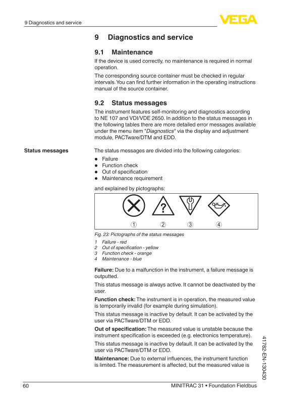
60
9 Diagnostics and service
MINITRAC 31 • Foundation Fieldbus
41782-EN-130430
9 Diagnostics and service
9.1 MaintenanceIfthedeviceisusedcorrectly,nomaintenanceisrequiredinnormaloperation.The corresponding source container must be checked in regular intervals.Youcanfindfurtherinformationintheoperatinginstructionsmanual of the source container.
9.2 Status messagesThe instrument features self-monitoring and diagnostics according toNE107andVDI/VDE2650.Inadditiontothestatusmessagesinthefollowingtablestherearemoredetailederrormessagesavailableunder the menu item "Diagnostics" via the display and adjustment module,PACTware/DTMandEDD.
Thestatusmessagesaredividedintothefollowingcategories:
• Failure• Function check• Outofspecification• Maintenancerequirementand explained by pictographs:
41 2 3Fig. 23: Pictographs of the status messages1 Failure - red2 Outofspecification-yellow3 Function check - orange4 Maintenance - blue
Failure: Due to a malfunction in the instrument, a failure message is outputted.Thisstatusmessageisalwaysactive.Itcannotbedeactivatedbytheuser.Function check: The instrument is in operation, the measured value is temporarily invalid (for example during simulation).This status message is inactive by default. It can be activated by the userviaPACTware/DTMorEDD.Outofspecification: The measured value is unstable because the instrumentspecificationisexceeded(e.g.electronicstemperature).This status message is inactive by default. It can be activated by the userviaPACTware/DTMorEDD.Maintenance:Duetoexternalinfluences,theinstrumentfunctionislimited.Themeasurementisaffected,butthemeasuredvalueis
Status messages

61
9 Diagnostics and service
MINITRAC 31 • Foundation Fieldbus
4178
2-EN
-130
430
still valid. Plan in maintenance for the instrument because a failure is expected in the near future (e.g. due to buildup).This status message is inactive by default. It can be activated by the userviaPACTware/DTMorEDD.
Thefollowingtableshowstheerrorcodesandtextmessagesinthestatus message "Failure"andprovidesinformationoncausesaswellas corrective measures.Example for a failure message
CodeText message
Cause Rectification
F008Error multi sensor communication
– Additionalsensorsnotswitchedon – EMCinfluences – No other sensor available
– Checkwiringbetweenthesensors – Connect the sensors correctly and make
them ready for operation
F013Sensor signals a fault
– Error on the current input – No valid measured value – Connectedinstrumentswithoutfunction
– Check current input – Check connected instruments (Slaves)
F016Adjustment data ex-changed
– Valuesofthemin.andmax.adjustmentexchanged
– Correct adjustment data
F017Adjustment span too small
– The values of the min. and max. adjust-ment are too close together
– Correct adjustment data
F025Invalidlinearizationtable
– Emptylinearizationtable – Wrongvalueinthelinearizationtable
– Createlinearizationtable – Correctlinearizationtable
F030Process value out of limits
– Processvaluesarenotwithintheadjusted measuring range
– Repeat adjustment
F034EPROMhardwareerror
– Electronics defective – Restart instrument – Exchanging the electronics
F035EPROM data error
– Error in the internal instrument com-munication
– Carry out a reset – Exchanging the electronics
F036Faulty program memory
– Errorduringsoftwareupdate – Repeatsoftwareupdate – Exchanging the electronics
F037RAMhardwareerror
– Error in RAM – Restart instrument – Exchanging the electronics
Failure

62
9 Diagnostics and service
MINITRAC 31 • Foundation Fieldbus
41782-EN-130430
CodeText message
Cause Rectification
F038Slave signals failure
– Connection cable to the Slave instrument interrupted
– InstrumentnotdefinedasSlaveinstru-ment
– Check the connection cable to the Slave instrument
– DefineinstrumentasSlave
F040Hardwareerror
– Sensor defective – Restart instrument – Exchanging the electronics
F041Photomultiplier error
– Error in the measured value recording – Restart instrument – Exchanging the electronics
F052Faultyconfiguration
– Invalid parameter adjustment – Carry out a reset
F066Faulty adjustment
– Adjustment not yet carried out – Errorduringadjustmentorwhenenteringthelinearizationtable
– Carrying out adjustment – Carryoutlinearization
F068Count rate too high
– Faulty instrument settings – Carry out a reset
F072Limit exceeded
– Faulty instrument settings – Carry out a reset
F073Error real value cor-rection
– Faulty real value correction – Carry out real value correction again
F080System error
– Instrument error – Restart instrument – Call our service
F086Communication error
– Error in the Fieldbus communication – Restart instrument – Call our service
F114Error real time clock
– Discharge accumulator – Readjust real time clock
F120Filter time error
– Faulty or missing instrument adjustment – Carrying out adjustment
F121Faulty participant list on the multisensor communication bus
– Slave instruments not found – Check Slave instruments – Check Slave list in Master instrument – Slaveinstrumentwithwrongaddress
F122Double addresses on the multisensor com-munication bus
– Instrumentaddressewasassignedseveral times
– Change instrument addresses
F123X-ray alarm
– External instruments cause radiation – Determine reason for X-ray alarm – In case of brief X-ray radiation: Monitor switchingoutputsforthistimemanually
F124Alarm due to in-creased radiation
– Radiation dose too high – Determine reason for increased radiation

63
9 Diagnostics and service
MINITRAC 31 • Foundation Fieldbus
4178
2-EN
-130
430
CodeText message
Cause Rectification
F125Ambient temperature too high
– Ambient temperature on the housing outsidethespecification
– Cooltheinstrumentorprotectitwithisolating material against radiation heat
Thefollowingtableshowstheerrorcodesandtextmessagesinthestatus message "Function check" and provides information on causes aswellascorrectivemeasures.
CodeText mes-sage
Cause Rectification
C029Simulation
– Simulation active – Finish simulation – Wait for the automatic end
after 60 mins.
Thefollowingtableshowstheerrorcodesandtextmessagesinthestatus message "Outofspecification" and provides information on causesaswellascorrectivemeasures.
CodeText mes-sage
Cause Rectification
S017Accuracy outside the specification
– Accuracy outside the specification
– Correct adjustment data
S025Badlineariza-tion table
– Badlinearizationtable – Carryoutlinearization
S038Slave outside thespecifica-tion
– Slaveoutsidethespecifica-tion
– Check Slave
S125Ambient tem-perature too high/toolow
– Ambient temperature too high/toolow
– Protectinstrumentwithisolating material against extreme temperatures
The instrument has no status messages to the section "Maintenance".
9.3 Rectify faultsThe operator of the system is responsible for taking suitable meas-ures to rectify faults.
Thefirstmeasuresare:
• Evaluation of fault messages via the indicating and adjustment module
• Checking the output signal
Function check
Outofspecification
Maintenance
Reaction when malfunc-tions occur
Procedure for fault recti-fication

64
9 Diagnostics and service
MINITRAC 31 • Foundation Fieldbus
41782-EN-130430
• Treatment of measurement errors
FurthercomprehensivediagnosispossibilitiesareofferedbyaPCwiththesoftwarePACTwareandsuitableDTM.In many case, the failure reasons can thus be determined and faults rectified.
Thefollowingtabledescribespossibleerrorswiththeoutputsignaland helps to remove them:
Error Cause Rectification
Output signal not stable Levelfluctuations Set damping according to the instrument via the display and adjustment module or PACT-ware/DTM
Output signal missing Electrical connection faulty Check connection according to chapter "Connection steps" and if necessary, correct ac-cording to chapter "Wiring plan"
Voltagesupplymissing Check cables for breaks; repair if necessary
Operatingvoltagetooloworload resistance too high
Check, adapt if necessary
Thefollowingtabledescribespossiblefaultsthatmaynotgenerateanerror message:
Error Cause Rectification
The instrument signals cov-eredwithoutcoveringwiththemediumThe instrument signals cov-eredwithcoveringwiththemedium
Voltagesupplymissing Check cables for breaks; repair if necessary
Operatingvoltagetooloworload resistance too high
Check, adapt if necessary
Electrical connection faulty Check connection according to chapter "Connection steps" and if necessary, correct ac-cording to chapter "Wiring plan"
Electronics defective Changetheswitchingbehaviourofthesensorsunder "Diagnosis/Simulation". If the instrument doesnotswitchover,senditinforrepair.
Buildupontheinnerwallofthe vessel
Remove buildupCheck the Delta I value.Improvetheswitchingthreshold-carryoutadouble point adjustment
Depending on the reason for the fault and the measures taken, the steps described in chapter "Setup" must be carried out again or must be checked for plausibility and completeness.
Should these measures not be successful, please call in urgent cases theVEGAservicehotlineunderthephoneno.+49 1805 858550.Thehotlineisalsoavailableoutsidenormalworkinghours,sevendaysaweekaroundtheclock.Sinceweofferthisserviceworldwide,thesupportisprovidedinEnglish. The service itself is free of charge, the only costs involved are the normal call charges.
Check output signal (level measurement)
Check output signal (level detection)
Reaction after fault recti-fication
24 hour service hotline

65
9 Diagnostics and service
MINITRAC 31 • Foundation Fieldbus
4178
2-EN
-130
430
9.4 Exchanging the electronics moduleIf the electronics module is defective, it can be replaced by the user.In Ex applications only one instrument and one electronics module withrespectiveExapprovalmaybeused.If there is no electronics module available on site, the electronics module can be ordered through the agency serving you. The electron-icsmodulesareadaptedtotherespectivesensoranddifferinsignaloutput or voltage supply.Thenewelectronicsmodulemustbeloadedwiththedefaultsettingsof the sensor. These are the options:
• In the factory• Or on site by the user
In both cases, the serial number of the sensor is needed. The serial numbers are stated on the type label of the instrument, on the inside ofthehousingaswellasonthedeliverynote.Whenloadingonsite,firstofalltheorderdatamustbedownloadedfrom the Internet (see operating instructions manual "Electronics module").
9.5 Software updateThefollowingcomponentsarerequiredtoupdatethesensorsoft-ware:
• Sensor• Voltagesupply• InterfaceadapterVEGACONNECT4• PCwithPACTware• CurrentsensorsoftwareasfileYoucanfindtheactualsensorsoftwareaswellasdetailedinfor-mation of the procedure under "www.vega.com/downloads" and "Software".Youcanfindinformationabouttheinstallationinthedownloadfile.
Caution:Instrumentswithapprovalscanbeboundtocertainsoftwarever-sions.Thereforemakesurethattheapprovalremainseffectivewithasoftwareupdate.Youcanfinddetailedinformationonwww.vega.com/downloads and "Approvals".
9.6 How to proceed in case of repairThefollowingprocedurerefersonlytothesensor.Shouldarepairofthesourcecontainerbenecessary,youcanfindtherespectiveinstructions in the operating instructions manual of the source con-tainer.Youcanfindarepairformaswellasdetailedinformationonhowtoproceed under www.vega.com/downloads and "Formsandcertifi-cates".

66
9 Diagnostics and service
MINITRAC 31 • Foundation Fieldbus
41782-EN-130430
Bydoingthisyouhelpuscarryouttherepairquicklyandwithouthav-ing to call back for needed information.Ifasensorrepairisnecessary,pleaseproceedasfollows:
• Printandfilloutoneformperinstrument• Clean the instrument and pack it damage-proof• Attach the completed form and, if need be, also a safety data
sheet outside on the packaging• Please ask the agency serving you for the address of your return
shipment.Youcanfindthecompetentagencyonourwebsitewww.vega.com.

67
10 Dismounting
MINITRAC 31 • Foundation Fieldbus
4178
2-EN
-130
430
10 Dismounting
10.1 Dismounting stepsWarning:Beforedismounting,beawareofdangerousprocessconditionssuchas e.g. pressure in the vessel, high temperatures, corrosive or toxic products etc.Take note of chapters "Mounting" and "Connecting to power supply" and carry out the listed steps in reverse order.
10.2 DisposalTheinstrumentconsistsofmaterialswhichcanberecycledbyspe-cialised recycling companies. We use recyclable materials and have designed the parts to be easily separable.Correctdisposalavoidsnegativeeffectsonhumansandtheenviron-mentandensuresrecyclingofusefulrawmaterials.Materials: see chapter "Technical data"Ifyouhavenowaytodisposeoftheoldinstrumentproperly,pleasecontact us concerning return and disposal.
WEEE directive 2002/96/EGThis instrument is not subject to the WEEE directive 2002/96/EG and therespectivenationallaws.Passtheinstrumentdirectlyontoaspe-cialised recycling company and do not use the municipal collecting points. These may be used only for privately used products according to the WEEE directive.

68
11 Supplement
MINITRAC 31 • Foundation Fieldbus
41782-EN-130430
11 Supplement
11.1 Technical dataGeneral data316L corresponds to 1.4404 or 1.4435Materials,non-wettedparts
Ʋ Scintillation material NaI (sodium iodide) Ʋ Aluminium die-casting housing Aluminiumdie-castingAlSi10Mg,powder-coated-basis:
Polyester Ʋ Stainless steel housing 316L Ʋ Sealbetweenhousingandhousingcover
NBR (stainless steel housing, investment casting), silicone (Aluminium housing)
Ʋ Inspectionwindowinhousingcover(optional)
Polycarbonate
Ʋ Ground terminal 316LProcessfittings
Ʋ Fastening lugs ø 9 mm (0.35 in), hole centre distance 119 mm (4.69 in)Weight
Ʋ Aluminiumhousing,withelectronics 4.1 kg (9 lbs) Ʋ Stainlesssteelhousing,withelectron-ics
9.1 kg (20.1 lbs)
Max.torque,mountingscrews-fasteninglugs on the sensor housing
50 Nm (36.88 lbf ft)
Max.torqueforNPTcableglandsandConduittubes Ʋ Aluminium/Stainless steel housing 50 Nm (36.88 lbf ft)
Input variableMeasured variable The measured variable is the intensity of the gamma ra-
diation of an isotope. If the radiation intensity decreases, e.g. due to increasing product density, the measured value of MINITRAC 31 changes in proportion to the density.
Analogue input Ʋ Input type 4 … 20 mA, passive Ʋ Internal load 250Ω
Switchinginput Ʋ Type of input - Open Collector 10 mA Ʋ Type of input - Relay contact 100 mA
Output variable - Level measurementOutput
Ʋ Signal digital output signal, Foundation Fieldbus protocol Ʋ Physical layer according to IEC 61158-2
Damping (63 % of the input variable) 0 … 999 s, adjustable

69
11 Supplement
MINITRAC 31 • Foundation Fieldbus
4178
2-EN
-130
430
Channel Numbers Ʋ Channel 1 Process value (level) Ʋ Channel 8 Electronics temperature Ʋ Channel 9 Pulse rate
Transmission rate 31.25 Kbit/sCurrent value 10 mA, ±0.5 mAResolution, digital > 0.1 mm (0.004 in)
Output variable - Density measurementOutput
Ʋ Signal digital output signal, Foundation Fieldbus protocol Ʋ Physical layer according to IEC 61158-2
Damping (63 % of the input variable) 0 … 999 s, adjustableChannel Numbers
Ʋ Channel 1 Process value (density) Ʋ Channel 3 Processtemperature(withexternaltemperaturesensor) Ʋ Channel 8 Electronics temperature Ʋ Channel 9 Pulse rate
Transmission rate 31.25 Kbit/sCurrent value 10 mA, ±0.5 mAResolution, digital > 0.1 mm (0.004 in)
Output variable - Level detectionOutput
Ʋ Signal digital output signal, Foundation Fieldbus protocol Ʋ Physical layer according to IEC 61158-2
Damping (63 % of the input variable) 0 … 999 s, adjustableChannel Numbers
Ʋ Channel 1 Processvalue(switchingstatus) Ʋ Channel 8 Electronics temperature Ʋ Channel 9 Pulse rate
Transmission rate 31.25 Kbit/sCurrent value 10 mA, ±0.5 mAResolution, digital > 0.1 mm (0.004 in)
Output variable - X-ray alarmOutput
Ʋ Signal digital output signal, Foundation Fieldbus protocol Ʋ Physical layer according to IEC 61158-2
Damping (63 % of the input variable) 0 … 999 s, adjustableChannel Numbers
Ʋ Channel 1 Process value

70
11 Supplement
MINITRAC 31 • Foundation Fieldbus
41782-EN-130430
Ʋ Channel 8 Electronics temperature Ʋ Channel 9 Pulse rate
Transmission rate 31.25 Kbit/sCurrent value 10 mA, ±0.5 mAResolution, digital > 0.1 mm (0.004 in)
Output variable - Real value correctionOutput
Ʋ Signal digital output signal, Foundation Fieldbus protocol Ʋ Physical layer according to IEC 61158-2
Damping (63 % of the input variable) 0 … 999 s, adjustableChannel Numbers
Ʋ Channel 1 Process value Ʋ Channel 8 Electronics temperature Ʋ Channel 9 Pulse rate
Transmission rate 31.25 Kbit/sCurrent value 10 mA, ±0.5 mAResolution, digital > 0.1 mm (0.004 in)
Relay outputOutput Relayoutput(SPDT),floatingspdtSwitchingvoltage
Ʋ Min. 10mV Ʋ Max. 253VAC,253VDC
Switchingcurrent Ʋ Min. 10 µA Ʋ Max. 3 A AC, 1 A DC
Breaking capacity Ʋ Min. 50 mW Ʋ Max. 750VAAC,40WDC
Ifinductiveloadsorstrongercurrentsareswitchedthrough,thegoldplatingontherelaycontactsurfacewillbe permanently damaged. The contact is then no longer suitableforswitchinglow-levelsignalcircuits.
Contact material (relay contacts) AgNi or AgSnO and Au plated
Transistor outputOutput Floating transistor output, permanently shortcircuit-proofLoad current < 400 mAVoltageloss <1VSwitchingvoltage <55VDCBlocking current < 10 µA

71
11 Supplement
MINITRAC 31 • Foundation Fieldbus
4178
2-EN
-130
430
Accuracy (according to DIN EN 60770-1)Process reference conditions according to DIN EN 61298-1
Ʋ Temperature +18 … +30 °C (+64 … +86 °F) Ʋ Relative humidity 45 … 75 % Ʋ Air pressure 860 … 1060 mbar/86 … 106 kPa (12.5 … 15.4 psig)
Repeatability ≤0.1%Deviationwithbulksolids The values depend to a great extent on the application.
Bindingspecificationsarethusnotpossible.DeviationunderEMCinfluence ≤1%
VariablesinfluencingmeasurementaccuracyTemperature drift - Digital output ±3 mm/10 K relating to the max. measuring range or
max. 10 mmAdditional deviation through electromag-netic interference acc. to EN 61326
< ±50 mm
Characteristics and performance dataStep response time5) ≤5s(withdamping1s)
Ambient conditionsAmbient, storage and transport tempera-ture
-40 … +60 °C (-40 … +140 °F)
Process conditionsFortheprocessconditions,pleasealsonotethespecificationsonthetypelabel.Thelowervaluealwaysapplies.Process pressure UnpressurizedProcess temperature (measured on the detector tube)
-40 … +60 °C (-40 … +140 °F)Withtemperaturesofmorethan60°Cwerecommendtheuseofwatercooling
Vibrationresistance6) mechanicalvibrationsupto1ginthefrequencyrange5…200Hz
Electromechanical data - version IP 66/IP 67Cable entry
Ʋ M20 x 1.5 2 x cable gland M20 x 1.5 (cable: ø 6 … 12 mm), 4 x blind plug M20 x 1.5Included: 1 x cable gland M20 x 1.5
Ʋ ½ NPT 5 x closing cap (red) ½ NPTIncluded: 3 x cable gland ½ NPT (cable: ø 6 … 12 mm), 4 x blind plug ½ NPT
Spring-loadedterminalsforwirecross-section Ʋ Massivewire,cord 0.2 … 2.5 mm² (AWG 24 … 14) Ʋ Strandedwirewithendsleeve 0.2 … 1.5 mm² (AWG 24 … 16)
5) Timespanafterasuddenmeasuringdistancechangebymax.0.5minliquidapplications,max2mwithbulksolidsapplications,untiltheoutputsignalhastakenforthefirsttime90%ofthefinalvalue(IEC61298-2).
6) Tested according to the guidelines of German Lloyd, GL directive 2.

72
11 Supplement
MINITRAC 31 • Foundation Fieldbus
41782-EN-130430
Display and adjustment moduleDisplay element DisplaywithbacklightMeasured value indication
Ʋ Number of digits 5 Ʋ Sizeofdigits W x H = 7 x 13 mm
Adjustment elements 4 keysProtection rating
Ʋ unassembled IP 20 Ʋ mountedintothehousingwithoutcover
IP 40
Material Ʋ Housing ABS Ʋ Inspectionwindow Polyester foil
Integrated clockDate format Day.Month.YearTime format 12 h/24 hTimezoneExfactory CET
Measurement electronics temeratureResolution 1 °C (1.8 °F)Accuracy ±1 °C (1.8 °F)
Voltage supplyOperating voltage
Ʋ Sensorpowersupply 20…72VDCor20…253VAC,50/60Hz Ʋ FF bus 9…32VDC
Electrical protective measuresProtection, depending on housing ver-sion
IP 66/IP 677)
Overvoltage category IIIProtection class I
ApprovalsInstrumentswithapprovalscanhavedifferenttechnicaldatadependingontheversion.For that reason the associated approval documents of these instruments must be carefully noted. Theyarepartofthedeliveryorcanbedownloadedunderwww.vega.com and "VEGA Tools" as wellasunder"Downloads" and "Approvals".
11.2 Supplementary information Foundation FieldbusThefollowingtablegivesyouanoverviewoftheinstrumentversionsandthecorrespondingdevicedescriptions,theelectricalcharacteristicsofthebussystemaswellastheappliedfunctionblocks.
7) Asuitablecableistheprerequisiteformaintainingtheprotectionrating.

73
11 Supplement
MINITRAC 31 • Foundation Fieldbus
4178
2-EN
-130
430
Revisions Data DD-Revision Rev_01
CFF-File 010101.cff
Device Revision 0101.ffo0101.sym
Cff-Revision xx xx 01
Devicesoftwarerevision > 1.5.0
ITK (Interoperability Test Kit) Number 6.0.1
Electricial Characteristics Physicial Layer Type Low-powersignaling,bus-pow-ered, FISCO I.S.
Input Impedance >3000Ohmsbetween7.8KHz-39KHz
Unbalanced Capacitance < 250 pF to ground from either in-put terminal
Output Amplitude 0.8VP-P
Electrical Connection 4 Wire
Polarity Insensitive Yes
Max. Current Load 10 mA
Device minimum operating voltage 9V
Transmitter Function Blocks Resource Block (RB) 1
Transducer Block (TB) 1
Standard Block (AI) 3
Execution Time 30 ms
Diagnostics Standard Yes
Advanced Yes
Performance No
Function Blocks Instantiable No
General Information LAS (Link Active Scheduler) No
Master Capable No
NumberofVCRs(VirtualCommunicationRelationships)
24
Function block Analog Input (AI)The function block "Analog Input (AI)" takes the original measured value selected by a Channel Number and makes it available to additional function blocks on its output.

74
11 Supplement
MINITRAC 31 • Foundation Fieldbus
41782-EN-130430
Fig. 24: Schematic presentation function block Analog Input (AI)
Parameter listThefollowingtablegivesyouanoverviewoftheparametersused.
FF descriptor Rel. In-dex
Description Unit
PRIMARY_VALUE 13 PRIMARY_VALUE(Linearizedvalue).Thisistheprocess value after min/max adjustment and Lin-earizationwiththestatusofthetransducerblock.Theunitisdefinedin"PRIMARY_VALUE_UNIT"
FF_PRIMARY_VAL-UE_UNIT
FF_PRIMARY_VALUE_UNIT
14 Selected unit code for "PRIMARY_VALUE" -
FF_VAPOR_DENSITY 15 DensitywithTemperaturecorrection FF_VAPOR_DENSI-TY_UNIT
FF_VAPOR_DENSITY_UNIT
16 Selected unit code for “FF_VAPOR_DENSITY” -
FF_PROCESS_TEM-PERATURE
17 Process temperature FF_PROCESS_TEM-PERATURE_UNIT
FF_PROCESS_TEM-PERATURE_UNIT
18 Selected unit code for “FF_PROCESS_TEMPER-ATURE”
-
FF_DENSITY 19 Density FF_DENSITY_UNIT
FF_DENSITY_UNIT 20 Selected unit code for “FF_DENSITY” -
FF_VOLUMETRIC_FLOW
21 Volumetricflow FF_VOLUMETRIC_FLOW_UNIT
FF_VOLUMETRIC_FLOW_UNIT
22 Selected unit code for “FF_VOLUMETRIC_FLOW” -
FF_WEIGHT 23 Weight on belt FF_WEIGHT_UNIT
FF_WEIGHT_UNIT 24 Selected unit code for “FF_WEIGHT” -
FF_BELT_SPEED 25 Belt speed FF_BELT_SPEED_UNIT
FF_BELT_SPEED_UNIT
26 Selected unit code for “FF_BELT_SPEED” -
FF_ELECTRONIC_TEMPERATURE
27 Electronics temperature FF_ELECTRONIC_TEMPERATURE_UNIT

75
11 Supplement
MINITRAC 31 • Foundation Fieldbus
4178
2-EN
-130
430
FF descriptor Rel. In-dex
Description Unit
FF_ELECTRONIC_TEMPERATURE_UNIT
28 Selected unit code for “FF_ELECTRONIC_TEM-PERATURE”
-
FF_COUNT_RATE 29 Count rate FF_COUNT_RATE_UNIT
FF_COUNT_RATE_UNIT
30 Selected unit code for “FF_COUNT_RATE” -
DEVICE_TAG 31 Tagname -
DEVICE_NAME 32 Device type -
DEVICE_STATE 33 Error code -
PEAK_MEAS_VAL_MIN 34 Pulse rate (min.) -
PEAK_MEAS_VAL_MAX
35 Pulse rate (max.) -
PEAK_TEMP_VAL_MIN 36 Electronics temperature (min.) -
PEAK_TEMP_VAL_MAX
37 Electronics temperature (max.) -
APPLICATION_TYPE_SEL
38 Selected application -
TEMP_COMP_UNIT 39 Selected unit code for process temperature -
DELTA_I 40 Calculated percent delta I -
GAUGE_TEMPERA-TURE
41 Electronics temperature -
DECAY_COMPENSA-TION_FACTOR
42 Factor for the decay compensation -
PMT_VOLTAGE_CALI-BRATION
43 Photomultiplier voltage on delivery -
CORRELATION_CO-EFF
44 Correlationcoefficientforlinearizertable -
ERROR_TEXT 45 Error text -
PMT_VOLTAGE_AC-TUAL
46 Current photomultiplier voltage -
STANDARDIZATION_FACTOR
47 Factor for the real value correction -
SERIALNUMBER 48 Serial number -
NAMUR_STATE 49 NAMUR state -
NULL_COUNT_RATE 50 Zero count rate -
COUNT_RATE_PMT 51 Pulseratephotomultiplier(rawvalues) -
ADJ_DENSITY_ABS_COEFF
52 Processabsorptioncoefficient -
DEV_SW_VER_ASCII 53 Softwareversion -
POINT_LEVEL_AD-JUST_MODE
54 Point level adjustment mode -
RELAY_VALUE_SEL 55 Relay basic value -

76
11 Supplement
MINITRAC 31 • Foundation Fieldbus
41782-EN-130430
FF descriptor Rel. In-dex
Description Unit
DIGITAL_IN 56 Frequencyofdigitalinput -
DIGITAL_IN_BOOL 57 State of digital input -
ANALOG_IN 58 Current on analog input -
FF_CHANNEL_AVAIL-ABLE
59 Available channels -
FF_CHANNEL_USED 60 Used channels -
Mapping of Process Value StatusHex Quality Sub-Status Condition
0x00 Bad Non-specific Unexpected error
0x01 Bad ConfigurationError ItwastriedtosetawrongunitwithFFinterfaceOn user error codes: 16, 17, 25, 52, 57, 66, 72, 117, 120
0x0C Bad Device Failure Five or more internal communications have failed while"ProcessDataUpdate".LastusablevalueisdisplayedOn user error codes: 8, 34, 35, 36, 37, 38, 73, 80, 86, 121, 122, 141
0x10 Bad Sensor Failure On user error codes: 40, 41, 53, 68, 123, 124, 125
0x1C Bad Out of Service Transducer block is in mode "Out of Service"Channel is not assigned to an AIFBChannel is not available in running application
0x20 Bad Transducer in MAN Transducer block is in mode "Manual"
0x44 Uncertain LastUsableValue Three or more internal communications have failed while"ProcessDataUpdate".Lastusablevalueisdisplayed
0x48 Uncertain Substitute On user error codes: 29
0x4C Uncertain InitialValue After startup of device or channel assignment in AIFBwaschanged.Thechannelunitmaybeun-knownuntilnext"ProcessDataUpdate"On user error codes: 13
0x80 Good (NC) Non-specific No errors concerning to channel handlingOn user error codes: 0, 33, 45, 71, 126, 127
Mapping of User Error Codes to FF Field DiagnosticsPriority Description User Error Codes NE-107 Status
31 Hardwarefailure 40, 41 FAILURE
30 Memory failure 34, 35, 36, 37 FAILURE
29 Softwarefailure 80 FAILURE
28 Paramererizationcorrupt 72 FAILURE
27 Undefined27 - -

77
11 Supplement
MINITRAC 31 • Foundation Fieldbus
4178
2-EN
-130
430
Priority Description User Error Codes NE-107 Status
26 Undefined26 - -
25 Paramererizationerror 16, 17, 25, 52, 53, 57, 66, 117, 120
FAILURE
24 ConflictinMGC 121, 122, 141 FAILURE
23 Communication error in MGC 8 FAILURE
22 MGC slave reports error 38 FAILURE
21 Undefined21 - -
20 Undefined20 - -
19 Undefined19 - -
18 Detector temperature critical 125 OUT_OF_SPEC
17 Errorwhileauto-standardization 73 FAILURE
16 Excessive radiation 123, 124 FAILURE
15 Input out of bounds 13 OUT_OF_SPEC
14 Errorwhilesignalprocessing 68 FAILURE
13 Undefined13 - -
12 Undefined12 - -
11 Undefined11 - -
10 Undefined10 - -
9 Undefined9 - -
8 Undefined8 - -
7 AITB simulated 29 FUNCTION_CHECK
6 Undefined6 - -
5 Undefined5 - -
4 Undefined4 - -
3 Undefined3 - -
2 Undefined2 - -
1 Errorwhiletrendrecording 126, 127 GOOD
0 Reserved - Reserved
Not displayed 33, 45, 71, 86 -
11.3 DimensionsThefollowingdimensionaldrawingsrepresentonlyanextractofallpossibleversions.Detaileddimensionaldrawingscanbedownloadedatwww.vega.com/downloads under "Drawings".

78
11 Supplement
MINITRAC 31 • Foundation Fieldbus
41782-EN-130430
Aluminium and stainless steel housing
242,
5 m
m (9
.55"
)
54,5
mm
(2.1
5")
9 m
m(0
.35"
)9
mm
(0.3
5")
175 mm(6.89")
90 mm(3.54")
100 mm(3.94")
143,5 mm(5.65")
169 mm(6.65")
116,5 mm(4.59")
119 mm(4.69")
M20x1,5/½ NPT
Fig. 25: Aluminium housing or stainless steel housing - Precision casting

79
11 Supplement
MINITRAC 31 • Foundation Fieldbus
4178
2-EN
-130
430
MINITRAC 31
57 m
m(2
.24"
)24
2,5
mm
(9.5
5")
Fig. 26: MINITRAC 31L Measuring range

80
11 Supplement
MINITRAC 31 • Foundation Fieldbus
41782-EN-130430
11.4 Industrial property rightsVEGA product lines are global protected by industrial property rights. Further information see www.vega.com.Only in U.S.A.: Further information see patent label at the sensor housing.VEGA Produktfamilien sind weltweit geschützt durch gewerbliche Schutzrechte.Nähere Informationen unter www.vega.com.Les lignes de produits VEGA sont globalement protégées par des droits de propriété intellec-tuelle. Pour plus d'informations, on pourra se référer au site www.vega.com.VEGA lineas de productos están protegidas por los derechos en el campo de la propiedad indus-trial. Para mayor información revise la pagina web www.vega.com.Линии продукции фирмы ВЕГА защищаются по всему миру правами на интеллектуальную собственность. Дальнейшую информацию смотрите на сайте www.vega.com.VEGA系列产品在全球享有知识产权保护。进一步信息请参见网站<www.vega.com>。
11.5 TrademarkAllthebrandsaswellastradeandcompanynamesusedarepropertyoftheirlawfulproprietor/originator.

81
INDEX
MINITRAC 31 • Foundation Fieldbus
4178
2-EN
-130
430
INDEX
AAccessories
– Display and adjustment module 10 – External display and adjustment unit 11 – Interface adapter 10
Adjustment 29, 35Adjustment data 41, 49Adjustment mode 46Adjustment point 46Adjustment system 27Applications 28, 34, 45, 54, 55
BBackground radiation 29, 34, 45Block operation 40, 48, 54, 56
CCable entry 19Check signal 64Connection procedure 20Connection technology 20Control areas 12
DDamping 30, 39, 50Date 42, 50Date of manufacture 43, 52Default values 31, 43, 51Delta I 47Device name 43, 52Device settings Copy 43, 52Displayed value 40, 49
EEDD (Enhanced Device Description) 59Error messages 60
FFaultrectification63FF parameter 74Functional principle 9Function blocks
– Analog Input (AI) 73
HHandling permit 11Heat 18
IInner diameter 35
Installation position 14Instrument features 43, 52Isotope
– Co-60 28, 34, 45, 53, 55 – Cs-137 28, 34, 45, 53, 55
KKey function 27
LLanguage 40, 48Linearization29,36
MMain menu 28, 33, 44, 53, 54Moisture 13
NNAMUR NE 107
– Failure 61 – Function check 63 – Maintenance 63 –Outofspecification63
PPackaging 10Peak value 41, 49PIN 42, 50
RRadiation protection 11Radiationsafetyofficer12Radiation source 28, 34, 45, 53, 55Real value correction 39, 54Relay 30, 39, 48Repair 65Replacement parts
– Electronics module 11Reset 30, 42, 50
SSensor status 41, 49Service hotline 64Simulation 41, 49Source container 11Status messages 60Storage 10
TTime 42, 50Type plate 7

82
INDEX
MINITRAC 31 • Foundation Fieldbus
41782-EN-130430
UUnit 45Units 29, 35
VVoltagesupply72
WWater cooling 18
XX-ray alarm 30, 52

83
Notes
MINITRAC 31 • Foundation Fieldbus
4178
2-EN
-130
430

Printing date:
VEGA Grieshaber KGAm Hohenstein 11377761 SchiltachGermany
4178
2-E
N-1
3043
0All statements concerning scope of delivery, application, practical use and operat-ing conditions of the sensors and processing systems correspond to the information available at the time of printing.Subject to change without prior notice
© VEGA Grieshaber KG, Schiltach/Germany 2013
Phone +49 7836 50-0Fax +49 7836 50-201E-mail: [email protected]