install using tundra cm series -...
TRANSCRIPT

Owner’s guide: HD1224 / HD1824 / HD2524
HDI1824 / HDI3024
Install using
Tundra CM Series installation kit
Ask your retailer !
www.tundrainternational.com

HD(i)-24V-GD-0512-EN 2
Table of contents
1 INTRODUCTION ..................................................................................................................................... 3
1.1 Disclaimer ........................................................................................................................................................... 3
1.2 Output waveform ................................................................................................................................................ 3
2 FRONT , REAR PANEL & REMOTE CONTROL .............................................................................. 3
3 PERMANENT INSTALLATION ............................................................................................................ 4
3.1 Recommended material ..................................................................................................................................... 4
3.2 Recommended tools ............................................................................................................................................ 5
3.3 Where to install ................................................................................................................................................... 5
3.4 Mounting the inverter ......................................................................................................................................... 5
3.5 Ground ................................................................................................................................................................ 6
3.6 Battery cables ...................................................................................................................................................... 6
3.6.1 Preparation of the cable connected to the “positive” end ............................................................................ 6
3.6.2 Preparation of the cable connected to the negative side .............................................................................. 7
3.7 Connecting the Inverter....................................................................................................................................... 7
3.8 Connection of the batteries ................................................................................................................................. 8
3.8.1 Positive Terminal ......................................................................................................................................... 8
3.8.2 Negative Terminal ....................................................................................................................................... 8
4 OPERATION ............................................................................................................................................. 8
4.1 Trouble loads ...................................................................................................................................................... 8
4.2 Microwave .......................................................................................................................................................... 9
4.3 Operating limits .................................................................................................................................................. 9
5 MAINTENANCE ....................................................................................................................................... 9
6 TROUBLESHOOTING ............................................................................................................................ 9
6.1 Television and CB radio interference ................................................................................................................. 9
6.2 Troubleshooting guide ...................................................................................................................................... 10
7 SPECIFICATIONS ................................................................................................................................. 11
8 LIMITED ONE-YEAR WARRANTY .................................................................................................. 13
HD(i)-24V-GD-0512-EN 3
1 Introduction
Congratulations! You have purchased one of the most sophisticated and reliable power inverters on the market today.
Incorporating some of the latest technological developments, it will give years of trouble free operation for your truck, boat, R.V.
or other.
In order to get the most out of your inverter, the installation procedure must be followed carefully and it must also be properly
used. Please thoroughly read this manual before installing and using your new inverter. It is important to pay special attention to
the CAUTION and WARNING statements in this manual as well as on the inverter. Should the inverter be exposed to rain,
moisture, or strong impact, have it inspected by a qualified technician before use.
WARNING! The electrical current at the entrance and exit of your inverter may cause severe personal injury;
make certain that you have read and understand all the parts of this manual before installing and
using your inverter.
WARNING! The inverter produces an electrical current similar to that found in most North American homes, with
all the accompanying dangers. Be sure to install the product out of the reach of children.
1.1 Disclaimer
Electrical codes vary depending on location and the type of installation. Electrical installations must meet local and national wiring
codes and should be performed by a qualified electrician.
The inverter’s specifications are subject to change without notice.
1.2 Output waveform
The AC output of your inverter is regulated to 120 volts and its waveform is called a “Modified Sine Wave.” It is a stepped
waveform, suitable for most AC loads, designed to have characteristics similar to sine waves delivered by utility power. Note that
our modified sine wave output power is much more efficient than the “square wave” generated by other inverters on the market
today.
The modified sine wave generated by your inverter is designed to have an RMS (Root Mean Square) voltage of 120 volts, the
same voltage as that coming out of standard household power. Most AC voltmeters are sensitive to the average value of the
waveform rather than the RMS value. They are calibrated for RMS voltage assuming the voltage waveform is “ pure sine wave.”
These meters may not read the modified sine wave correctly; they will read about 2-20 volts lower. To read the voltage correctly,
you must use a true RMS reading voltmeter.
2 Front , rear panel & remote control
FRONT PANEL
ON/OFF switch: The ON/OFF switch turns the inverter’s control circuit ON and OFF. It does not disconnect power
from the inverter; you must disconnect the AC (120 volts) and DC (24 volts) power before
working on any circuits connected to the inverter. When the switch is on but no power is being
supplied to a load, the inverter draws less than 500 mA. This is a very low current draw but left in this
state the inverter will eventually drain your batteries until its automatic shut down at 22 volts (see
4.3).
AC Outlets: The maximum output of your inverter is assumed to go through the two AC outlets. HD Models are
also equipped with one hard wire outlet which can be used as the only output socket.
CAUTION! Leave in the OFF position during the installation.
HD(i)-24V-GD-0512-EN 4
REAR PANEL
Chassis ground screw: The chassis ground screw must be properly connected to the chassis of your vehicle before operating
the inverter.
Fan(s): In order for the inverter to properly operate, the fan(s) opening must never be obstructed. Allow at
least six inches of clearance around the inverter for airflow. All fans are thermostatic and operate
upon the interior temperature of inverter.
REMOTE CONTROL
ON/OFF: Your inverter is equipped with one 6 meters jack remote switch. The remote switch allows you to
mount your inverter out of sight and turn it ON or OFF from a convenient location. The ON/OFF
switch on the inverter’s front panel must be turned on for the remote to be operational.
Input Voltage: By pressing the “SELECT” button until the “INPUT VOLTAGE ” light comes on, the battery voltage
indicator displays the voltage at the input terminal of the inverter. Usually this voltage is very close to
the battery voltage and the difference, if any, is caused by the resistance of the cables and
connections. A regular maintenance will contribute to minimize the possible resistance (see 5).
Output Power: By pressing the “SELECT” button until the “OUTPUT POWER” light comes on, the watts indicator
displays the current provided by the inverter in KW. 1 KW = 1000 watts. If you read 1.20, it means
the inverter is providing 1200 watts.
“FAULT” light: An audible alarm will sound announcing a faulty condition such as: low or high battery voltage and
overload.
“OVERTEMP” light: An audible alarm will sound announcing an overtemp condition.
“LVP” on display: Indicates the inverter is in Low input Voltage Protection mode (see 4.3).
“OLP” on display: Indicates the inverter is in High input voltage Protection mode or if your consumption exceeds the
nominal capacity of the inverter (see 4.3).
3 Permanent Installation
The use of the Tundra International installation kits is strongly recommended. These complete installation kits are custom
designed to maximize performance. It has been developed to promote safe installation and to help eliminate the difficult task of
sourcing the requisite and right material.
3.1 Recommended material HD1224 HD & HDI1824 HD2524& HDI3024
- Tundra CM series installation kit CM1000 CM1200/1500 CM1800/2000
Or
- Welding cable AWG #4 AWG #2 AWG #1/0
- Battery copper cable No. 8 AWG
- PVC strain relief for flexible cable ½” ½” ¾”
- 6 Tin plated terminal lugs
- CNL fuse block
- CNL fuse 100A 150A 200A
- Plastic « loom » tubing
- Heavy duty AC power distribution center
- Red and black heat shrinkable tubing
- Plastic cable ties
- Clamps and bolts
HD(i)-24V-GD-0512-EN 5
3.2 Recommended tools
- Hand held crimping tool for terminal lugs * Mandatory
- Hollow punch or hole saw for metal
- Drill bit set for metal
- Screw driver set
- Open end wrench set
- Side cutters
- Power drill
CAUTION! Before installation, make sure that the inverter is turned “OFF.”
3.3 Where to install
Your inverter should be installed in a location that meets the following requirements:
- Dry: Keep the inverter away from any water or moisture.
- Cool: Ambient air temperature should be between 32 and 85 degrees Fahrenheit (0 and 30o Celsius).
- Ventilated: Ensure that the unit is located in a well-ventilated compartment. At least 6 inches of clearance are
required around the inverter for air flow. Verify that all ventilation openings on the unit (front and rear
panels) are not obstructed.
CAUTION! To avoid fire hazards and/or overheating, do not cover or obstruct any ventilation openings. Do not
install the inverter in a zero clearance compartment.
- Safe: Do not install the inverter in the same compartment as batteries, or in any compartment capable of
storing flammable liquids (such as gasoline). Power inverters may produce sparks that can result in fire
if exposed to flammable vapors.
WARNING! This equipment contains components that tend to produce arcs or sparks. To reduce the risk
of fire or explosion, do not install in a compartment containing batteries or flammable
materials, or in a location that requires ignition protected equipment.
- Close to batteries: Install the inverter as close as possible to the batteries (but not in the same compartment) in order to
minimize the cable length required to connect the inverter to the batteries. It is better and cheaper to run
longer AC wire (between the inverter and your appliances) than DC cables (between the inverter and
the batteries).
3.4 Mounting the inverter
When you have decided where to place it, mount the inverter on a flat surface using the mounting flanges. Mounting hardware
should be corrosion resistant, and 1/4” or larger. The inverter may be mounted on a vertical surface (the fans’ opening must not
point up or down) or on a horizontal surface. Upside down installation is not recommended, as it may put too much stress on the
housing of your power inverter.
If your inverter is equipped with a remote control, plug its cable into the remote switch jack on the front or rear panel of the
inverter.
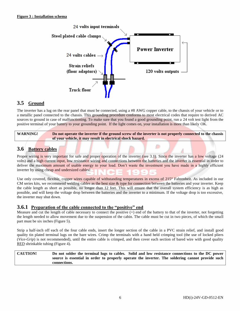
Close to the inverter, drill two holes in the truck’s floor and install the two strain reliefs about 3 inches apart (Figure 3).
HD(i)-24V-GD-0512-EN 6
Figure 3 : Installation schema
3.5 Ground
The inverter has a lug on the rear panel that must be connected, using a #8 AWG copper cable, to the chassis of your vehicle or to
a metallic panel connected to the chassis. This grounding procedure conforms to most electrical codes that require to derived AC
sources to ground in case of malfunctioning. To make sure that you found a good grounding point, run a 24 volt test light from the
positive terminal of your battery to your grounding point. If the light comes on, your installation is more than likely OK.
WARNING! Do not operate the inverter if the ground screw of the inverter is not properly connected to the chassis
of your vehicle, it may result in electrical shock hazard.
3.6 Battery cables
Proper wiring is very important for safe and proper operation of the inverter (see 3.1). Since the inverter has a low voltage (24
volts) and a high current input, low resistance wiring and connections between the batteries and the inverter is essential in order to
deliver the maximum amount of usable energy to your load. Don’t waste the investment you have made in a highly efficient
inverter by using cheap and undersized cables!
Use only covered, flexible, copper wires capable of withstanding temperatures in excess of 215° Fahrenheit. As included in our
CM series kits, we recommend welding cables as the best size & type for connection between the batteries and your inverter. Keep
the cable length as short as possible, no longer than 12 feet. This will ensure that the overall system efficiency is as high as
possible, and will keep the voltage drop between the batteries and the inverter to a minimum. If the voltage drop is too excessive,
the inverter may shut down.
3.6.1 Preparation of the cable connected to the “positive” end Measure and cut the length of cable necessary to connect the positive (+) end of the battery to that of the inverter, not forgetting
the length needed to allow movement due to the suspension of the cabin. The cable must be cut in two pieces, of which the small
part must be six inches (Figure 5).
Strip a half-inch off each of the four cable ends, insert the longer section of the cable in a PVC strain relief, and install good
quality tin plated terminal lugs on the bare wires. Crimp the terminals with a hand held crimping tool (the use of locked pliers
(Vice-Grip) is not recommended), until the entire cable is crimped, and then cover each section of bared wire with good quality
RED shrinkable tubing (Figure 4).
CAUTION! Do not solder the terminal lugs to cables. Solid and low resistance connections to the DC power
source is essential in order to properly operate the inverter. The soldering cannot provide such
connections.

HD(i)-24V-GD-0512-EN 7
Figure 4 : Terminals’ crimping procedure
3.6.1.1 Fuse A main fuse must be installed in the battery casing on the positive cable (+) between the batteries and the inverter, as close as
possible to the batteries. In this way (and in the event of cable rupture), the DC current would be cut at the batteries and would not
cause a fire.
Figure 5 : Fuse schema
We recommend a “CNL” type fuse, mounted on a “CNL” fuse holder like to ones included in our CM series kits. Plug one
terminal of the small and the long cable’s sections on the fuse holder, as illustrated in figure 5, and install the fuse. Without
tightening them too much, the terminals must be solidly fixed onto the fuse holder, and must not be able to move around.
CAUTION! Not installing a fuse can result in fire that may cause severe injuries and/or damages.
3.6.2 Preparation of the cable connected to the negative side Determine and cut the length of cable which you need to connect the negative side (-) of the battery to that of the inverter, without
forgetting the necessary length to allow movements due to the suspension of the cabin. Strip approximately a half-inch of
insulation from the two ends of the cable, insert the cable through the second PVC strain relief, and install good quality tin plated
terminal lugs on the stripped sections. Crimp the terminals with a hand held crimping tool (the use of a locked plier (Vice-Grip) is
not recommended) until the whole cable is crimped and then cover each section of stripped cable with good quality BLACK
shrinkable tubing (refer to Figure 4).
3.7 Connecting the Inverter
The next step is to make sure that the inverter is turned OFF. Insert the rubber insulators (included with the inverter) on the
terminal lugs and connect the cables (terminal lugs) to the inverter’s DC input terminals: the terminal covered with the RED shrink
tube to the positive (+) pole and the terminal covered with the BLACK shrink tube to the negative (-) pole. Make a secure
connection using the nuts included with the inverter. The terminal must not move around on the DC terminal, but it must not be
too tight either. The rubber insulators will protect the DC connections and will prevent the terminal from being touched by other
metallic pieces.
HD(i)-24V-GD-0512-EN 8
CAUTION! Never put a washer or a nut between the terminal lugs and the 24 volts DC input terminals; this
results in poor conductivity and may cause the inverter to overheat and cause a fire.
Tighten the PVC strain relief nut on the cables until the rubber seal is properly compressed and the cables cannot move. Run the
cables under your cab and cover them with plastic loom (included in our CM series kits) to prevent damage from road debris.
Fasten both cables together every 4 inches with plastic cable ties; try to run both DC (24 volts) cables as close as possible
together to reduce the risk of interference (see 6.1) with your television or CB radio. While keeping in mind to allow cables to
move with your cabin air suspension, secure the cables to the chassis from the cabin’s floor to the batteries with several metallic
clamps covered with ruber (included in our CM series kits). These clamps will prevent the cables from being cut or damaged by
the vehicle’ vibrations.
3.8 Connection of the batteries
If you are working with a multiple battery bank, choose a battery with no accessory connected, as it will extend your batteries’ life.
Before going further, it is important to correctly identify the cable connected to the positive terminal of the inverter, and the one
connected to the negative terminal. The cables must go from the positive terminal of the inverter to the positive terminal of
the battery, and of the negative terminal of the inverter to the negative terminal of the battery. Incorrectly connecting the
battery and inverter will damage your inverter permanently, and is not covered by the warranty. Always connect the
positive terminals before the negative.
CAUTION! Reversing the polarity when connecting the DC cables will permanently damage your inverter. THIS
IS NOT COVERED BY THE WARRANTY.
3.8.1 Positive Terminal Always connect the positive terminals before the negative. Plug the small section of the cable connected to the positive terminal of
the inverter to the positive terminal of the battery, by solidly fixing the terminal with the nut. Without tightening them too much,
the terminals must not be able to move around.
3.8.2 Negative Terminal The last step is to connect the cable between the negative terminal of the inverter to the negative terminal of the battery, by solidly
fixing the terminal with the nut. Without tightening them too much, the terminals must not be able to move around.
WARNING! You may observe a spark when making the cable connections since current may flow and charge
capacitors in the inverter. This is normal. Do not make cable connections in the presence of
flammable fumes; it may result in explosion and/or fire.
4 Operation
To operate the power inverter, turn it on by using the ON/OFF switch on the front panel and then by the remote switch (if
equipped). The inverter is now ready to deliver AC 120 volts power to your load. If you are operating several loads from the
inverter, turn them on separately after the inverter itself has been turned on. This will ensure that the inverter does not have to
deliver the starting power for all the loads at once.
4.1 Trouble loads
The waveform of your inverter is called a “Modified Sine Wave.” It is a stepped waveform suitable for most AC loads, designed to
have characteristics similar to sine wave delivered by utility power. Some appliances, however may not adequately filter the
waveform produced by the inverter and could, although unlikely, be damaged. If you are unsure about powering any device with a
modified sine wave power inverter, contact the manufacturer of the device. None of these potential problems can happen with the
Tundra International pure sine wave inverters (HTS series).
HD(i)-24V-GD-0512-EN 9
4.2 Microwave
The power rating used with microwave ovens is the cooking power which refers to the power being delivered to the food being
cooked. The actual operating power requirement rating is 40% to 100% higher than the advertised cooking power. The actual
power consumption is usually stated on the back of the microwave. If the operating power requirement cannot be found on the
back of the microwave, check the owner's manual or contact the manufacturer.
4.3 Operating limits
Power output: Your inverter is designed to deliver its full output power continuously, and has a double power surge
capacity for less than 1 second.
Input voltage: The inverter will operate with input voltages between 20 and 30 volts (see specs). Optimum
performance is achieved, however, with input voltages between 24.0 and 28.0 volts. If the voltage drops
lower than a certain preprogrammed level (see 7), the low battery warning alarm will sound.
The inverter will shut down if the voltage drops below a certain preprogrammed level (see 7). The
“LVP” code will be displayed on the remote. This protects your batteries from being over-discharged.
The inverter will not restart unless the input voltage exceeds 26.4 volts.
The inverter will shut down if the voltage exceeds 30 volts or if your consumption exceeds the nominal
capacity of the inverter. The “OLP” code will be displayed on the remote. This protects the inverter
from excessive input voltage. While the inverter incorporates protection against over voltage, it may still
be damaged if the input voltage exceeds 32 volts.
5 Maintenance
Very little maintenance is required to keep the inverter operating properly. You should clean the exterior with a dry cloth to
prevent dust accumulation. A regular maintenance check is recommended, DC input bolts or screws should be tightened
periodically, cables should also be inspected for solidity and exterior condition. You must also keep your batteries as clean as
possible to prevent current loss that may affect inverter operation.
CAUTION! If you work on the DC input terminals of your power inverter, disconnect both wires at the battery
side to avoid any short circuit.
6 Troubleshooting
6.1 Television and CB radio interference
Operating your inverter can interfere with television and CB radio reception. If this occurs, the following steps may help to
eliminate the problem:
Make sure that your inverter is properly grounded to the chassis of your vehicle (see 3.5).
Reduce power consumption while watching television
Move the television as far as possible from your inverter
Run both DC cables as close as possible together with cable ties.
HD(i)-24V-GD-0512-EN 10
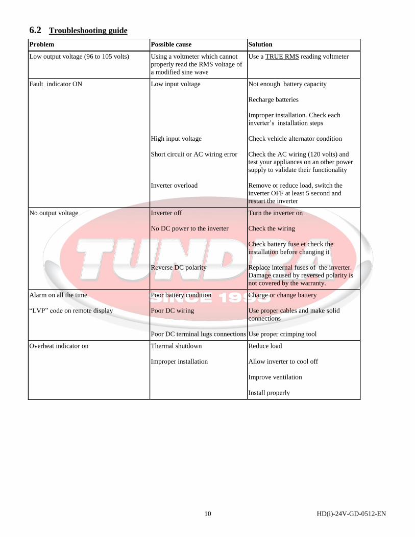
6.2 Troubleshooting guide
Problem Possible cause Solution
Low output voltage (96 to 105 volts) Using a voltmeter which cannot
properly read the RMS voltage of
a modified sine wave
Use a TRUE RMS reading voltmeter
Fault indicator ON Low input voltage
High input voltage
Short circuit or AC wiring error
Inverter overload
Not enough battery capacity
Recharge batteries
Improper installation. Check each
inverter’s installation steps
Check vehicle alternator condition
Check the AC wiring (120 volts) and
test your appliances on an other power
supply to validate their functionality
Remove or reduce load, switch the
inverter OFF at least 5 second and
restart the inverter
No output voltage Inverter off
No DC power to the inverter
Reverse DC polarity
Turn the inverter on
Check the wiring
Check battery fuse et check the
installation before changing it
Replace internal fuses of the inverter.
Damage caused by reversed polarity is
not covered by the warranty.
Alarm on all the time
“LVP” code on remote display
Poor battery condition
Poor DC wiring
Poor DC terminal lugs connections
Charge or change battery
Use proper cables and make solid
connections
Use proper crimping tool
Overheat indicator on Thermal shutdown
Improper installation
Reduce load
Allow inverter to cool off
Improve ventilation
Install properly
HD(i)-24V-GD-0512-EN 11
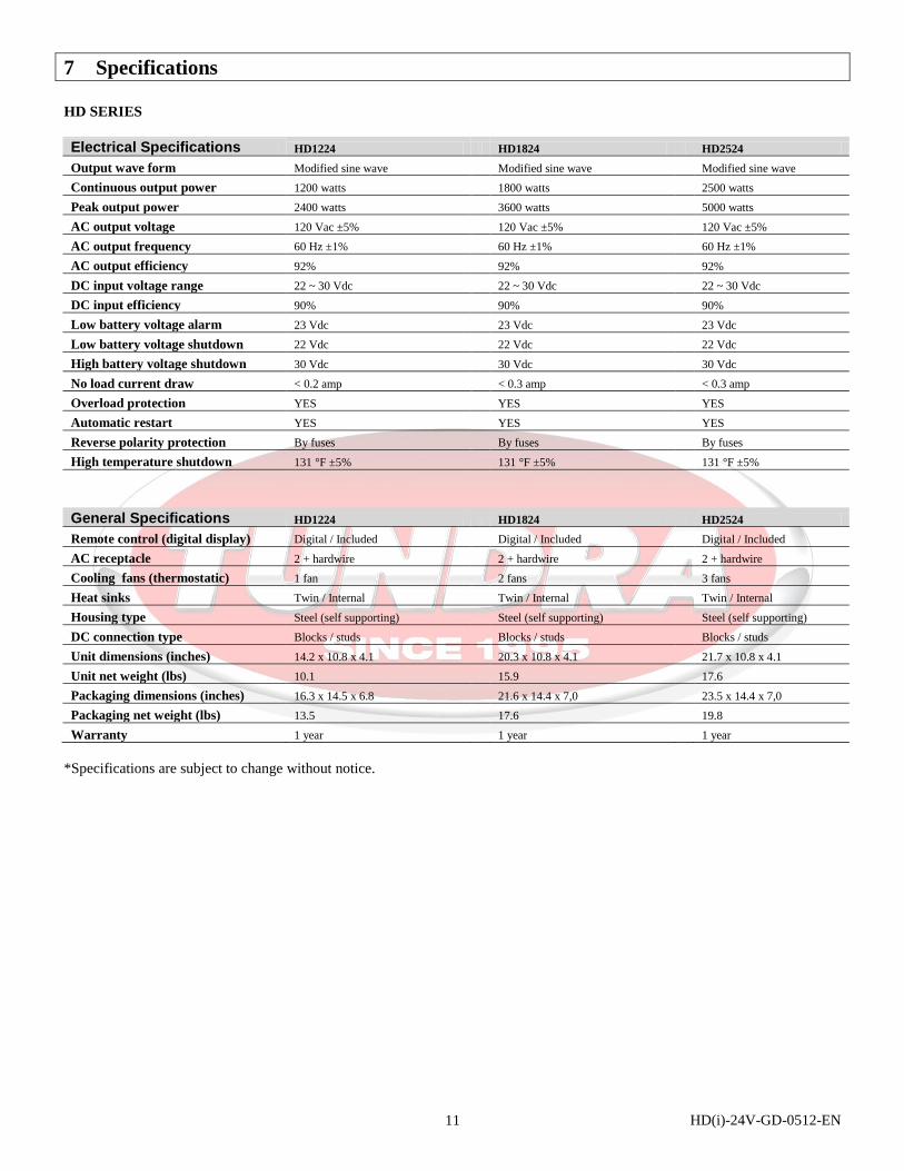
7 Specifications
HD SERIES
Electrical Specifications HD1224 HD1824 HD2524
Output wave form Modified sine wave Modified sine wave Modified sine wave
Continuous output power 1200 watts 1800 watts 2500 watts
Peak output power 2400 watts 3600 watts 5000 watts
AC output voltage 120 Vac ±5% 120 Vac ±5% 120 Vac ±5%
AC output frequency 60 Hz ±1% 60 Hz ±1% 60 Hz ±1%
AC output efficiency 92% 92% 92%
DC input voltage range 22 ~ 30 Vdc 22 ~ 30 Vdc 22 ~ 30 Vdc
DC input efficiency 90% 90% 90%
Low battery voltage alarm 23 Vdc 23 Vdc 23 Vdc
Low battery voltage shutdown 22 Vdc 22 Vdc 22 Vdc
High battery voltage shutdown 30 Vdc 30 Vdc 30 Vdc
No load current draw < 0.2 amp < 0.3 amp < 0.3 amp
Overload protection YES YES YES
Automatic restart YES YES YES
Reverse polarity protection By fuses By fuses By fuses
High temperature shutdown 131 °F ±5% 131 °F ±5% 131 °F ±5%
General Specifications HD1224 HD1824 HD2524
Remote control (digital display) Digital / Included Digital / Included Digital / Included
AC receptacle 2 + hardwire 2 + hardwire 2 + hardwire
Cooling fans (thermostatic) 1 fan 2 fans 3 fans
Heat sinks Twin / Internal Twin / Internal Twin / Internal
Housing type Steel (self supporting) Steel (self supporting) Steel (self supporting)
DC connection type Blocks / studs Blocks / studs Blocks / studs
Unit dimensions (inches) 14.2 x 10.8 x 4.1 20.3 x 10.8 x 4.1 21.7 x 10.8 x 4.1
Unit net weight (lbs) 10.1 15.9 17.6
Packaging dimensions (inches) 16.3 x 14.5 x 6.8 21.6 x 14.4 x 7,0 23.5 x 14.4 x 7,0
Packaging net weight (lbs) 13.5 17.6 19.8
Warranty 1 year 1 year 1 year
*Specifications are subject to change without notice.

HD(i)-24V-GD-0512-EN 12
HDi SERIES
Electrical Specifications HDi1824 HDi3024
Output wave form Modified sine wave Modified sine wave
Continuous output power 1800 watts 3000 watts
Peak output power 3600 watts 6000 watts
AC output voltage 120 Vac ±5% 120 Vac ±5%
AC output frequency 60 Hz ±1% 60 Hz ±1%
AC output efficiency 92% 92%
DC input voltage range 20 ~ 30 Vdc 20 ~ 30 Vdc
DC input efficiency 90% 90%
Low battery voltage alarm 21 Vdc 21 Vdc
Low battery voltage shutdown 20 Vdc 20 Vdc
High battery voltage shutdown 30 Vdc 30 Vdc
No load current draw < 0.3 amp < 0.3 amp
Overload protection YES YES
Automatic restart YES YES
Reverse polarity protection By fuses By fuses
High temperature shutdown 131 °F ±5% 131 °F ±5%
General Specifications HDi1824 HDi3024
Remote control (digital display) Digital / Included Digital / Included
AC receptacle 2 + hardwire 2 + hardwire
Cooling fans (thermostatic) 2 fans 3 fans
Heat sinks Twin / Internal Twin / Internal
Housing type Steel (self supporting) Steel (self supporting)
DC connection type Blocks / studs Blocks / studs
Unit dimensions (inches) 20.3 x 10.8 x 4.1 21.7 x 10.8 x 4.1
Unit net weight (lbs) 15.9 17.6
Packaging dimensions (inches) 21.6 x 14.4 x 7,0 23.5 x 14.4 x 7,0
Packaging net weight (lbs) 17.6 19.8
Warranty 1 year 1 year
*Specifications are subject to change without notice.

HD(i)-24V-GD-0512-EN 13
8 Limited one-year warranty
Tundra International Inc. warrants its power inverters against defects in workmanship and materials for a period of one (1) year
from the date of first consumer purchase. This warranty is given only to the first end-use purchaser of the product.
This limited warranty is void if the unit is abused, modified, installed improperly, if the housing has been removed, if the serial
number is missing, or if the original identification markings have been defaced, altered, or removed. Tundra International Inc. is
not liable for any incidental, consequential or other damages arising from the use, misuse, or operation of this product; including,
without limitation, damages resulting from loss of use, cost of removal, installation, or troubleshooting of the customer's electrical
systems.
Tundra International Inc. will, without charge, repair or replace, at its option, a defective inverter upon delivery, with all shipping
and handling costs, and full insurance, paid for by the purchaser, to the Tundra International Service Department: 2041-A
Léonard-De Vinci, Ste-Julie, Quebec, J3E 1Z2. The following information, clearly printed, must be included with the defective
unit: Your name and street address, a daytime telephone number and/or email address, a detailed description of the problem and
the proof of the date of first consumer purchase, such as duplicated sale receipt.
