install & service manual - pbs16a
TRANSCRIPT

tyco Fire & Integrated Solutions
SYSTEM PBS-16 A
FIRE CONTROL SYSTEM
INSTALLATION AND SERVICING MANUAL
Version 2.1 - 23 May 1990
The information in this manual is subject to change without notice and does not represent a commitment on the part of WORMALD SIGNALCO A/S. Distributors will be updated at regular intervals, but are responsible themselves for maintaining their own copies up- dated. WORMALD SIGNALCO A/S makes no warranty of any kind with regard to this document. Use, duplication, translation or disclosure is allowed at the responsibility of the user.

INSTALLATIONAM) SERVICING MANUAL PREFACE PBS16 SYSEh4 PAGE (ii)
PBS-l6 INTELLIGENT FIREALARM
... AND CONTROL. SYSTEM . ... :. .
. .. . .. INSTALLATION AND SERVICING MANUAL ..
CONTENTS
SAFETY
WARRANTIES AND CONSTRAINTS
INTRODUCTION
GENERAL DESCRIPTION
MODULE DESCRIPTIONS
CARD DESCRIPTIONS
INSTALLATION
COMMISSIONING
SERVICING
'APPEDICES
INDEX
INSTALLATION AND SERVICING UANUAL PREFACE P S 1 6 SYSTEM PAGE (iii)
APPENDICES
Default Programme
Service and Commisioning Tools
Dip-switch Settings
Testing Modules In Isolation
Setting Up The COM-16 ~ommuhication Card
Printer Connections
Keypad Service Functions
Microprocessor and EPROM markings
Loop and Line Numbers
IF-16 Connections
RU-16 and Connection Of RS-16, RS-32 and RS-56
Configuring and Operating The SRP-16
Technical Specifications
Conditions of Sale
INDEX
INSTALLATION AND SERVICING MANUAL SAFEIY AND WARRANTTES PS16 SYSIB.4 PAGE 1
PBS-16 INTELLIGENT FIRE ALARM
AND CONTROL SYSTEM
INSTALLATION
AND
SERVICING MANUAL
SAFETY
The PBS-16 system is powered by one or more charger units delivering 24V DC each with a secondary voltage supply consisting of a bank of 24V batteries. The charger units are con- nected to the mains and care must be taken when working with such a unit, disconnecting it from the mains if necessary.
. There is no other part. of the PBS-16 system-thatisxun directly from the mains.Note that . .
. . .equipment controlled by the PBS-16 system may be powered directly from the mains, and that this must be checked for the specific installation.
WARRANTIES AND CONSTRAINTS
Please note that repairs or modifications to the equipment without written consent from WORMALD SIGNALCO A/S invalidates the warranty.
See Appendix N for full details on Conditions of Sale.

INSTALLATION AND SERVICING MANUAL CHAPTER ONE INTRODUCTION PBS-16 SYSTEM PAGE 2
CHAPTER ONE
INTRODUCTION
WARNING!
NO WORK MAY BE DONE ON THIS SYSTEM OTHER THAN BY
APPROVED PERSONNEL.
The PBS-16 Fire Alarm System is of modular construction.. .The .basic module, PBS-16, with inputs from up to 1536 detectors or sensors, and outputs to-alarms and other equip- ment, forms a complete fire alarm system with a full range of features. Further modules, which may be in any combination, enable the system to be expanded to meet the most complex requirements and to be integrated with other systems.
The modular construction enables the system to be engineered to suit individual installa- tion requirements, while retaining its full range of facilities.
Because systems are individually engineered, the installation, commissioning and servicing information given here must be supported by the installation drawings for installation and commissioning, by the record drawings for servicing, and by other data for the particular installation.
. . This information is provided as a separate document package.
This manual gives, or gives reference to, all the information necessary for the installation, commissioning and servicing of the PBS-16 Fire Alarm System.
It begins by defining three distinct sets of input conditions, followed by an outline descrip- tion of the basic system, based on a block diagram, and introducing the PBS-16 module.
. . . . This is followed by an outline description of the remaining modules in the PBS-16 system, with a block diagram showing their use in an expanded system.
Further information is then given on each module.

INSTALLATION AND SERVICING MANUAL CHAPTER ONE: INTRODUCTION PBS-16 SYSTEM PAGE 3
All the above provides background information for the installation, commissioning and . . . . . servicing information,.which follows.
Appendices give data on recommended input devices, and other reference data.

INSTALLATION AND SERVICING MANUAL CHAPTER TWO: GENERAL DESCRIPTIONPBS-16 SYSTEM PAGE 4
CHAPTER TWO
GENERAL DESCRIPTION
CONTENTS
INPUT SYSTEMS Conventional Detectors Addressable Conventional (Digital) Detectors Addressable Analogue Sensors
THE BASIC SYSTEM: ADDRESSABLE SENSORS Inputs Data Collection Data Processing outputs Manual Control
THE BASIC SYSTEM: CONVENTIONAL DETECTORS
EXPANDED SYSTEM
ILLUSTRATIONS
Fig
2.1 Basic PBS-16 System 2.2 Inputs : Conventional Detectors 2.3 Inputs : Addressable Conventional Detectors (Nittan) 2.4 Inputs: Addressable Conventional Detectors (BRK) 2.5 Inputs: Addressable Analogue Sensors , 2.6 Extended PBS-16 System Showing PBS-16 Family of Modules
INSTALLATION AND SERVICING MANUAL CHAPTER TWO: GENERAL DESCRIPTION PBS-16 S Y m PAGE
CHAPTER TWO
GENERAL DESCRIPTION .
2.1 INPUT SYSTEMS
Three distinct systems of input devices are possible in the PBS-16 alarm system.
Connections to the Control Panel may be in Lines or Loops.
A Line or Loop may be one of three types:
(a) Conventional detectors. This is normally referred to asconventional lines or loops.
(b) Addressable conventional detectors. Usually referred to as digital lines or loops.
(c) Addressable analogue sensors. Referred to as analogue lines or loops.
Manual Call Points (MCPs) and other hard-contact devices may be used with any of these types.
It is not possible to mix lines and loops in the same system. Within the same system all modules must either have loops connected to them or they must all have lines connected.
Different types of lines or loops cannot be mixed on the same module. However, PBS-16 and US-16 modules in the same system may have lines or loops of different types. Some care must be taken when modules with different types of detection lines or loops are linked together. The PS-16 controlling the whole system must have core software made for an analogue system if any one of the modules in the system have loops or lines with analogue sensors. Otherwise the PS-16 core software may be of the digital addressed type.
. The markings on the EPROMS indicate what type of loops or lines they are intended to .
work with, and also if they are for a loop or a line configuration. Please refer to Appendix H for further detail on processor and EPROM markings.
2.1.1 Conventional Detectors (Fig 2.2)
. , . A Conventional Line is a pair of wires with detection devices connected across it. AnEnd Of Line (EOL) device enables a 4.5 mA current to flow through the line, thus confirming that it is not open circuit.
The operation of any device produces a short circuit, increasing the current flow through it

INSTALLATION AND SERVICING MANUAL CHAPTER TWO: GENERAL DESCRIPTION PBS-16 SYSTEM PAGE 6
to the alarm level of 20 mA.
. A Conventional Loop has both ends of the pair of wires connected to the Control Panel, enabling monitoring from either end. This provides a safeguard against a break in the wires. With each loop occupying two line inputs to. the Control Panel, only half as many loops may be connected, as lines.
The Control Panel is able to distinguish between 4.5mA (quiescent), 20mA (alarm) and . zero current (fault), but cannot identify the device within the line or loop.
Each line or loop represents one zone.
In this context, a detector is a two-stage device, either quiescent or in alarm. It changes 'state from open circuit to short circuit when the parameter being monitored crosses a preset threshold.
2.1.2 Addressable Conventional (Digital) Detectors (Figs 2.3 and 2.4)
Instead of detection devices being connected across the line or loop, address units are so connected, and the detectors are connected to these.
The Control Panel addresses each unit in turn. When addressed, the address unit reports its status.
In this system, the same three conditions are possible as in the Conventional system; that is, a 4.5mA current pulse represents the quiescent condition, a 20mA pulse the alarm condi- tion, and zero current, a fault condition. The significant difference is that the Control Panel is able to identify the particular address initiating an alarm or fault condition.
One type of address unit has one detector associated with it. Other address units enable one or more MCPs or other hard contact devices to be connected to one address unit, thus forming a sub-zone. Any sub-zone has an EOL device to enable open circuit fault monitor- ing. This EOL device is normally a resistor which is placed inside the furthermost unit on the line connected to the address unit. Alarm or fault identification is only as far as the address of the sub-zone. The Control Panel cannot detect which device within the sub- zone produced the alarm or fault.
, 2.1.3 Addressable Analogue Sensors (Fig 2.5)
Instead of detectors being connected across the line or loop, address units are so con- nected, and analogue sensors are connected to them.
An analogue sensor provides an output that is a function of the value of the parameter being monitored. It does not have a changeover between quiescent and alarm conditions. That threshold is provided by the Control Panel, where its value is preset, and compensa- tion is made for ageing effects of the sensor, thus reducing the number of false alarms from this cause. When compensation limits are reached, a fault condition, rather than an alarm condition, is produced by the Control Panel.

INSTALLATION AND SERVICING MANUAL CHAPTER TWO: GENERAL DESCRIPTION PBS-16SYSI'EM PAGE 7
The Control Panel addresses each unit in turn. When addressed, each unit reports its status.
One type of address unit has one analogue sensor associated with it.
The address unit has only two current levels: zero for a fault condition and 20mA for moni- toring. The 20 mA current pulse is of variable duration, the duration being a measure of the analogue value of the parameter-being measured by the sensor.
Interpretation of the analogue value into quiescent or alarm condition is a function of the Control Panel.
Other types of address unit enable MCPs and other hard contact devices to be connected to the line or loop. Several hard contact devices may be connected to the same address unit, thus forming a sub-zone. This zone is monitored for open circuit by including an EOL resistor in the device connected furthest away from the address unit.
2.2 THE BASIC SYSTEM: ADDRESSABLE SENSORS (Fig 2.1)
The basic system has a number of detectors or sensors connected to each of a number of inputs to the PBS-16 module. Equipment intended for operation if there is a fire alarm is connected to output relays fitted in the PBS-16 module.
The module consists of two separate units, linked together:
(a) A PS-16 Information and Control Panel, which carries displays and a keypad, enabling operator control of the system, and providing information to the operator.
(b) A US-16 Control and Monitor Unit, which contains the data collection, data processing and output equipment.
The PS-16 module is microprocessor-based, and operates under the control of a predeter- mined programme. It continuously checks the keypad for any input from an operator, and guides the operator by using the Message Display while a function is being entered. When the function is correctly entered it processes the request made by the operator. It displays
. , requested data in the Message Display and passes. on required data to the other modules. The PS-16 module also interrogates each US-16 module in the system at regular intervals to ensure that the communication between the various modules functions properly. The PS-16 module also displays all alarms and fault messages received from other modules.
The module continuously scans each line or loop in turn, and within each line or loop, monitors the output of each detector or sensor for a normal return, a fault condition or an alarm condition. It also monitors the Control Panel for any keypad input from an operator, and runs a self-test programme. Each cycle of operations is completed in approximately two seconds.
So long as normal conditions are maintained, there is no output from the Control Panel.
INSTALLATION AND SERVICING MANUAL CHAPTER TWO: GENERAL DESCRIPTION PBS-16 SYSTEM PAGE 8
2.2.1 Inputs
Inputs may be address units associated with addressable sensors or detectors, or from conventional detectors. In each case, each device is connected across a pair of wires. There may be up to 32 conventional detectors connected across one pair of wires, or 96 addressable sensors or detectors.
If one end of. the pair of wires is connected to the PBS-16 module, and the other end termi- nated, the pair of wires' is called a Line: There may be up to 16 lines connected to the module, allowing up to 96 X 16 = 1536 sensors.
If both ends of the pair of wires connect to the module, the pair of wires is called a Loop. Up to eight loops may be connected, allowing up to 768 sensors.
Each line or loop is identified by a two-digit address, using numbers consecutively from 01 upwards. .The loop or line number is derived from the address of the US-16 it is connected to. Each address unit in a line or loop is similarly identified, from 01 up to 96. Thus each address unit (and consequently, each sensor) has an unique four-digit address consisting of the Line/loop address followed by its own two-digit number.
2.2.2 Data Collection
The PBS-16 module scans each address in turn, monitoring the condition of the associated sensor. Analogue values are fed through an analogue to digital converter in the Control Panel before being processed further. The module also monitors the Control Panel keypad to determine if it is being used, and monitors the auxiliary inputs. Also the com bus is continuously monitored for fault or input from other modules connected in the system.
2.2.3 Data Processing
From its own stored reference data, the module is able to determine if each sensor is in its normal state, in a fault condition, or in an alarm condition.
For the normal condition of the sensors, the data processing produces no outputs, but if one sensor shows an abnormal condition on two successive scans, then outputs are pro- duced.
. . . . . For .a fault alarm condition; outputs operate a buzzer and provide data to the displays. Data is stored, and if a printer is connected to the system, the data is printed out.
For a fire alarm condition, an output provides data to the displays; data is stored, and if a printer is connected to then-system, the data is printed out; :Separately, according to the reference data for the particular sensor, other selected outputs are provided. The refer- ence data is contained in the customised Cause and Effect programme, or in its absence, in the default programme.
INSTALLATION AND SERVICING MANUAL CHAPTER TWO: GENERAL DESCRIPTION PBS-16 SYSTEM PAGE 9
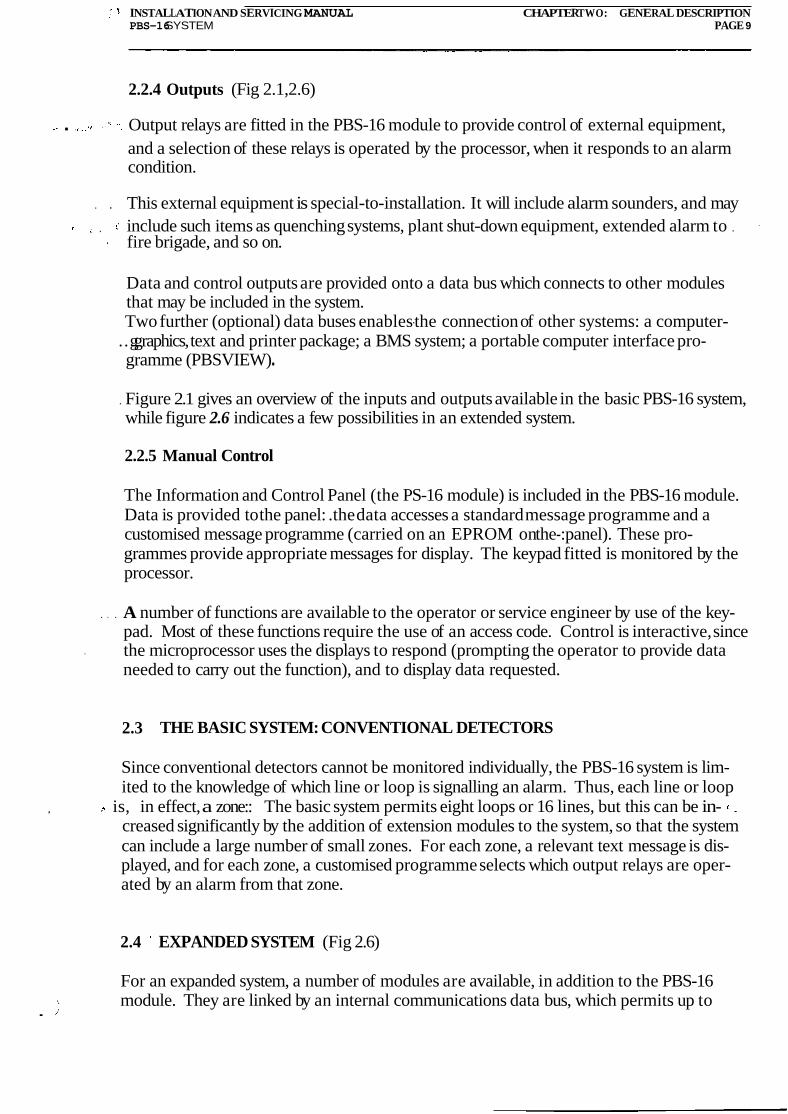
2.2.4 Outputs (Fig 2.1,2.6)
. Output relays are fitted in the PBS-16 module to provide control of external equipment, and a selection of these relays is operated by the processor, when it responds to an alarm condition.
. . This external equipment is special-to-installation. It will include alarm sounders, and may , include such items as quenching systems, plant shut-down equipment, extended alarm to . .
fire brigade, and so on.
Data and control outputs are provided onto a data bus which connects to other modules that may be included in the system. Two further (optional) data buses enables-the connection of other systems: a computer-
..g graphics, text and printer package; a BMS system; a portable computer interface pro- gramme (PBSVIEW) .
. Figure 2.1 gives an overview of the inputs and outputs available in the basic PBS-16 system, while figure 2.6 indicates a few possibilities in an extended system.
2.2.5 Manual Control
The Information and Control Panel (the PS-16 module) is included in the PBS-16 module. Data is provided to the panel: .the data accesses a standard message programme and a customised message programme (carried on an EPROM on the-:panel). These pro- grammes provide appropriate messages for display. The keypad fitted is monitored by the processor.
. . . A number of functions are available to the operator or service engineer by use of the key- pad. Most of these functions require the use of an access code. Control is interactive, since
. the microprocessor uses the displays to respond (prompting the operator to provide data needed to carry out the function), and to display data requested.
2.3 THE BASIC SYSTEM: CONVENTIONAL DETECTORS
Since conventional detectors cannot be monitored individually, the PBS-16 system is lim- ited to the knowledge of which line or loop is signalling an alarm. Thus, each line or loop
, is, in effect, a zone:: The basic system permits eight loops or 16 lines, but this can be in- .
creased significantly by the addition of extension modules to the system, so that the system can include a large number of small zones. For each zone, a relevant text message is dis- played, and for each zone, a customised programme selects which output relays are oper- ated by an alarm from that zone.
2.4 EXPANDED SYSTEM (Fig 2.6)
For an expanded system, a number of modules are available, in addition to the PBS-16 module. They are linked by an internal communications data bus, which permits up to
.
.
. INSTALLATION AND SERVICING MANUAL CHAPTER TWO: GENERAL DESCRIPTION PBS-16SYSTEM PAGE 10
fifteen modules to be connected to the bus (including the PBS-16). An example of an expanded system is given in Fig 2.6.
Each module operates Gom a 24V DC supply, which is fed via a PBS-16 or a US-16 module from either a centralised or a local supply.
I I I I
DISPLAY I
PS-16 INFORMATION AND
CONTROL PANEL
RS-232C (USUALLY PRINTER) COM. BUS FOR CONNEC- TION OF OTHER UNlTS OR MODULES.
RS-232C, 20 mA LOOP OR RS-485 NORMALLY RS-232C FOR COMPUTER CONNECTION.
COMMON FAULT RELAY (ON I
PS-16, BUT CONNECTION TER- M I N A L SON US-16). (AUX. REL)
4 ALARM SOUNDER OUTPUTS
INPUTS OF 16 LINES OR 8 LOOPS WITH UP TO 32 CONVENTIONAL DETEC-TORS OR 96 ADDRESS UNITSPER LINE OR LOOP. US-16 3 CONTROL RELAY OUTPUTS
CONTROL AND MONITORUNIT
SLAVE UNIT RS-16, RS-32 OR 3 AUXILIARY INPUTS
THREE 24V DC, 1A OUTPUTS
COMMON FAULT RELAY O/P
CHARGER 24V DC
BATTERY BACKUP 21V DC SUPPLY
MAINS MONITORING .
PBS-16 MODULE
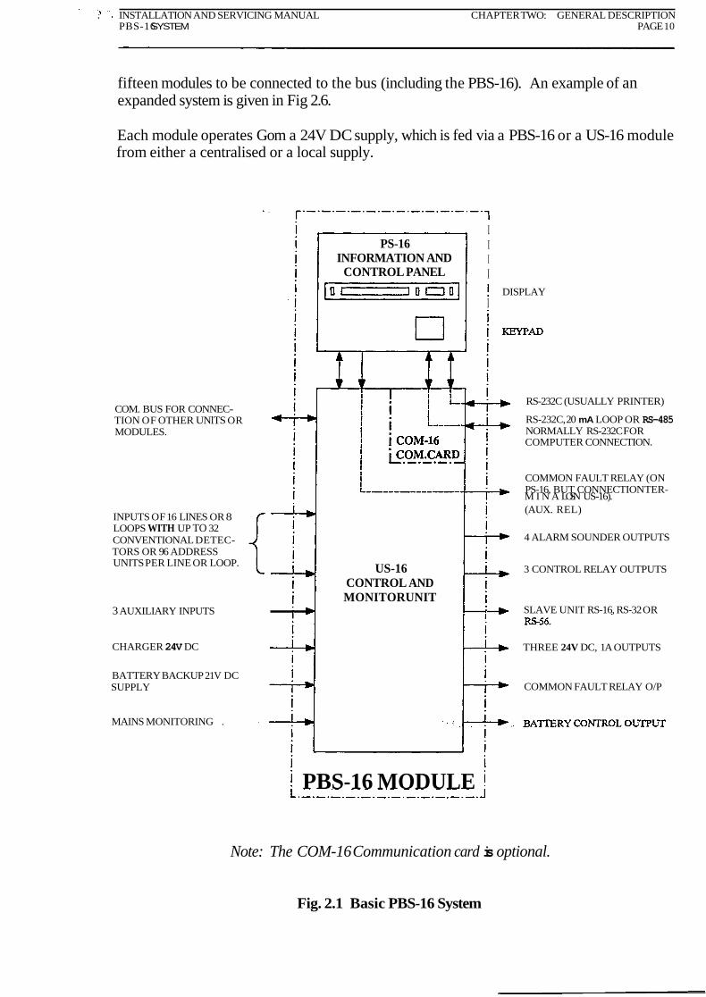
Note: The COM-16 Communication card is optional.
Fig. 2.1 Basic PBS-16 System

INSTALLATION AND SERVICING MANUAL CHAPTERTWO: GENERAL DESCRIPTIONPBS-16 SYSTEM PAGE 11
(a) LineWith Conventional Detectors
(b) h o p With Conventional Detectors
0 0 0' 0 0 0 LOOP TO CONTROL PANEL
0 0 +O LINE TO CONTROL PANEL.
MAXIMUM 32 DETECTORS.
MAXIMUM 32 DETECTORS. . I
0 0 0 0 0 0
0 0
The maximum number of devices in a line or loop is 32.
Hard-contact devices (MCP's, door switches, etc) may be any normally-open type.
Detectors may be only:
Nittan NID58 Series, BRK 1800EC, Cerberus F712.
Fig. 2.2 Inputs: Conventional Detectors
INSTALLATION AND SERVICING MANUAL CHAPTERTWO: GENERAL DESCRIPTION PSB-16 SYSTEM PAGE 12
detector. EOL
LINE TO CONTROL PANEL. + 0 MAXIMUM 96 ADDRESS UNITS
Sub-zone with EOL
resistor fitted in the last
device connected.
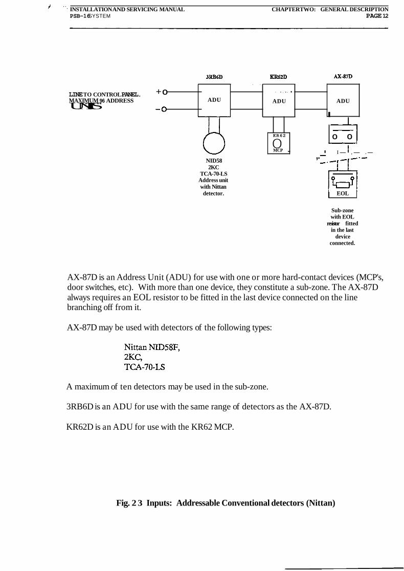
AX-87D is an Address Unit (ADU) for use with one or more hard-contact devices (MCP's, door switches, etc). With more than one device, they constitute a sub-zone. The AX-87D always requires an EOL resistor to be fitted in the last device connected on the line branching off from it.
AX-87D may be used with detectors of the following types:
ADU
I I
A maximum of ten detectors may be used in the sub-zone.
. . . . . . ADU ADU
KR62
0 MCP
3RB6D is an ADU for use with the same range of detectors as the AX-87D.
. .
0 0 I
KR62D is an ADU for use with the KR62 MCP.
- I- ,- .- ,.-' NID58 2KC
TCA-70-LS Address unit with Nittan
Fig. 2 3 Inputs: Addressable Conventional detectors (Nittan)

. . INSTALLATION AND SERVICING MANUAL CHAPTER TWO: GENERAL DESCRIPTION PBS-16 SYSTEM PAGE 13
BRK 2800EC BRK 5850EC
Sub-zone with EOL
resistor fitted in the last
device connected.
ADU
.
LINE TO CONTROL PANEL. + O MAXIMUM 96 ADDRESS ADU UNITS.
AX-87D is an Address Unit (ADU) for use with one or more .hard-contact devices (MCP's, door switches, etc). With more than one device, they constitute a sub-zone. The AX-87D always requires an EOL resistor to be fitted in the last device connected on the Line branching off from it.
. . . . ADU
AX-87D may be used with detectors of the following types:
t I I
Nittan NID58F, 2KC, TCA-70-LS
KR62
0 MCP
A maximum of ten detectors may be used in the sub-zone.
0 0
I I
B201D is an ADU for use with the BRK 1800EC, 2800EC and 5850EC detectors.
KR62D is an ADU for use with the KR62 MCP.
. BRK 1800C
Fig. 2.4 Inputs: Addressable Conventional detectors (BRK)

, INSTALLATION AND SERVICING MANUAL CHAPTER W O : GENERAL DESCRIPTION PBS-16 SYSTEM PAGE 14
Sub-zone. with EOL
resistor fined in the last
device connected.
LINE TO CONIROL PANEL + O MAXIMUM % ADDRESS UNITS
AX-87AD is an Address Unit (ADU) for use with 'one or more .hard-contact devices (MCP's, door switches, etc). With more than one device, they constitute a sub-zone. The AX-87AD always requires an EOL resistor to be fitted in the last device connected on the line branching off from it.
AX-87AD may be used with detectors of the following types:
A maximum of ten detectors may be used in the sub-zone.
ADU ADU
I I
3RB5AW is an ADU for use with the AW range of detectors.
KR62
0 MCP
KR62A is an ADU for use with the KR62 MCP.
. , . . . .
0 0
Fig. 2.5 Inputs: Addressable Analogue Sensors
.
ADU
AW Range of detectors

INSTALLATION AND SERVICING MANUAL CHAPTER TWO:GENERAL DESCRIPTION PBS-16SYSTEM PAGE 15
NOTE: PBS-16 MODULE
. . . . ESSENTIALS OF BASIC SYSTEM IS
SHOWN IN HEAVY OUTLINE (FIG 2.1) INFORMATION
COMMON FAULT RELAY
I CONTROL
PANEL ( A U XREL)
. . . . . .
8 DETECTIONLOOPS OR 16 DETECTIONLINES. (SEE FIGS 2.2TO 2.5)
CONTROLAND
MONITORUNIT
RS-232C, 20mA LOOP OR RS-485 FOR CONNECTION US-16 OF A PC OR OTHER PBS-16 SYSTEMS. (Only availablewhena COM-16 cardis fitted).
RS-232C PORT (USUALLY USED FOR PRINTER). (Onlyavailablewhen a COM-16 cardis fitted).
3 CONTROL RELAY OUTPUTS
3 x 24V DC, 1A OUTPUTS
COMMON FAULT RELAY
I- + 24V DC INPUT
MASTER MASTERR E L A Y RELAY
UNIT UNIT 16 SEPERATELY PROGRAMABLE R E L A YOUTPUTS
16 SEPERATELY PROGRAMABLE RELAY OUTPUTS RU-16 RU-16
16 ANALOGUE I N P U T SEACH TREATED AS A LOOP
I I
MAINS IN
RELAY SLAVE UP TO 224 OUTPUTSDEPENDING ON HOW MANY AND WHICH TYPE OF I RS-UNITSARE CONNECTED
RS-16,RS-32 OR RS-56 I RELAY SLAVE
UP TO W OUTPUTS DEPENDING OH UP TO FOUR HOW MANYAND WHICH TYPE OF
RS-16, RS-32OR RS-UNITS ARE CONNECTED
Fig. 2.6 Extended PBS-16 System Showing Family of Modules
EARTH CONNECTION L . . BATTERY
The internal communication bus is linked through modules connected. l h e links arebrokenin masterPBS-16 Up to 15modules (including PBS-16) may be connected. Each unitcontaininga l o o pcard countsasone module. SRP-16 is not included when calculatingnumber ofmodulesbut it mustbe included when the totalload on the communication bus is considered. Each module connected draws approximately 1.5mA (PBS-16 module draws 2.5mA). The totalloadshould not exeed27mA.
.
RELAYSLAVE Unit. UP TO 56OUTPUTS DEPENDING ON
ANY ONE OF WHICH RS-UNIT IS CONNECTEDRS-16, RS-32 OR
RS 56. . .
24VDC INPUT MIMIC PANEL
MADE OF LOOP CARD PLACED ON IF-16
24V DC INPUT UP TO 240 LEDS CAN BECONTROL Four RS-units may be CONTROLLED BY ONE LOOP
AND connectedto the loopcard. CARD. (Max.4 X RS-56 in addition MONITORING to the loop cardsown 16outputs). If
UNIT more outputs are required a second INPUTSAND OUTPUTSAS FOR Imp cardmust beadded. Each Imp U S - 1 6INCLUDED W PBS-16 US16
I RELAY SLAVE
UP TO 56 OUTPUTS DEPENDING ON UNIT. WHICH RS-UNITIS CONNECTED ANY ONE OF
RS-16, RS-32 OR RS-56.
card counts as one module.
L SRP-l6 REPEATER 24V DC WPUT
PANEL

INSTALLATION AND SERVICING MANUAL CHAPTER THREE: MODULE DESCRIPTIONS PBS-16 SYSTEM PAGE 16
. CHAPTER THREE
MODULE DESCRIPTIONS
CONTENTS
3.1 PBS-16
3.2 PS-16 INFORMATION AND CONTROL PANEL
3.3 US-16 CONTROL AND MONITOR UNIT
3.4 SRP-16 REPEATER PANEL
3.5 RU-16 MASTER RELAY UNIT
3.6 RU-16I MASTER RELAY AND INPUT UNIT
3.7 RS-16, RS-32, RS-56 RELAY SLAVE UNITS
3.8 MIMIC PANEL DRIVER (IF-16, Loop Card, RS-Units)
3.9 BRP-16 FIRE BRIGADE PANEL
ILLUSTRATIONS
Fig
3.1 Straps on the IF-16
INSTALLATION AND SERVICING MANUAL CHAPTER THREE: MODULE DESCRIPTIONS PBS-16SYSTEM PAGE 17
CHAPTER THREE
MODULE DESCRIPTIONS . . '
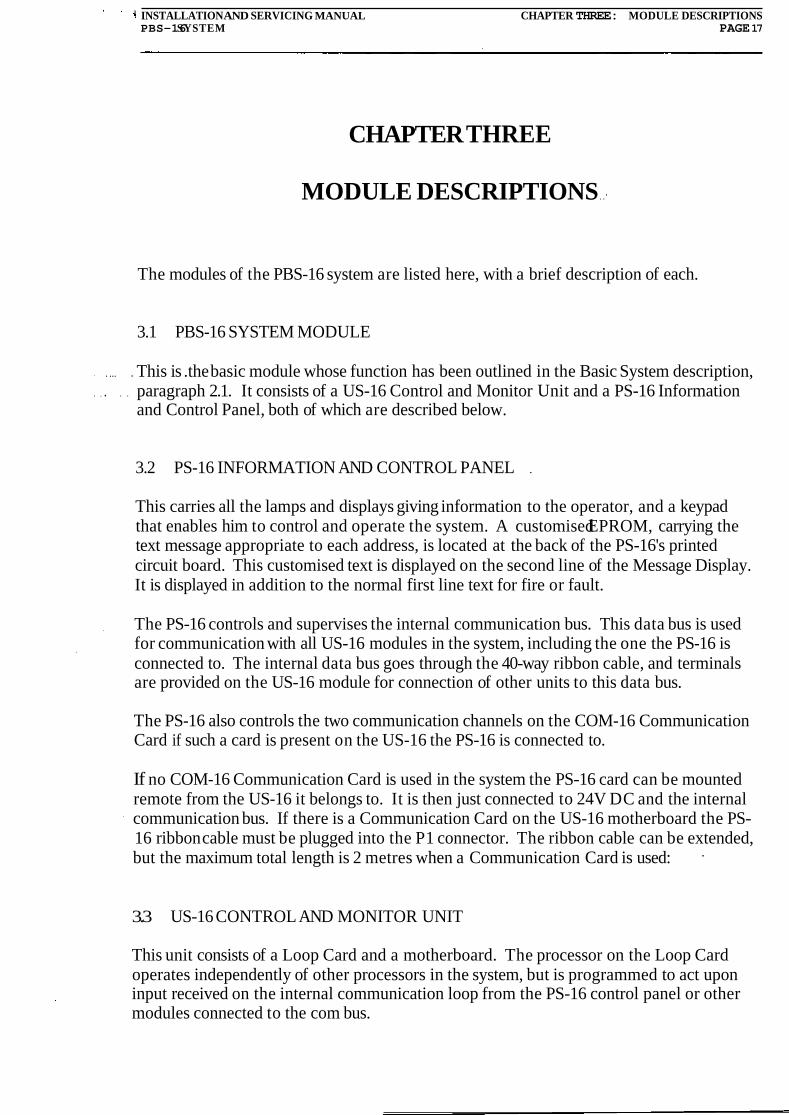
The modules of the PBS-16 system are listed here, with a brief description of each.
3.1 PBS-16 SYSTEM MODULE
. ... . This is .the basic module whose function has been outlined in the Basic System description, . , . . . paragraph 2.1. It consists of a US-16 Control and Monitor Unit and a PS-16 Information
and Control Panel, both of which are described below.
3.2 PS-16 INFORMATION AND CONTROL PANEL .
This carries all the lamps and displays giving information to the operator, and a keypad that enables him to control and operate the system. A customised EPROM, carrying the text message appropriate to each address, is located at the back of the PS-16's printed circuit board. This customised text is displayed on the second line of the Message Display. It is displayed in addition to the normal first line text for fire or fault.
. The PS-16 controls and supervises the internal communication bus. This data bus is used ,
for communication with all US-16 modules in the system, including the one the PS-16 is connected to. The internal data bus goes through the 40-way ribbon cable, and terminals are provided on the US-16 module for connection of other units to this data bus.
The PS-16 also controls the two communication channels on the COM-16 Communication Card if such a card is present on the US-16 the PS-16 is connected to.
If no COM-16 Communication Card is used in the system the PS-16 card can be mounted remote from the US-16 it belongs to. It is then just connected to 24V DC and the internal communication bus. If there is a Communication Card on the US-16 motherboard the PS- 16 ribbon cable must be plugged into the P1 connector. The ribbon cable can be extended, but the maximum total length is 2 metres when a Communication Card is used: .
3.3 US-16 CONTROL AND MONITOR UNIT
This unit consists of a Loop Card and a motherboard. The processor on the Loop Card operates independently of other processors in the system, but is programmed to act upon input received on the internal communication loop from the PS-16 control panel or other modules connected to the com bus.

. ' INSTALLATION AND SERVICING MANUAL CHAPTER THREE: MODULE DESCRIPTIONS PBS-16 SYSTEM PAGE 18
The motherboard provides connection terminals for the following:
- Eight Detection Loops or 16 Detection Lines - The Internal Communication Bus - Auxiliary Relay (can only be used when a PS-16 is connected) .
- Four Alarm Bell Circuits Three Control Relays
- Fault Relay . . Voltage Failure Circuit
- Three Auxiliary Inputs - Three 24VDC Supply Outputs - . External Buzzer - A Relay Slave Unit
I n addition it has a connector for connection of a PS-16 module and a slot for the COM-16 -Communication Card.
. The US-16 is a data collection, processing and output unit. It is used in conjunction with the PS-16 module, as part of the PBS-16 module. It receives inputs from the lines or loops of sensors and from three auxiliary inputs. In addition it receives input on the internal communication bus from the operator's keypad on the PS-16 module or other units con- nected to the combus. It provides outputs to the lamps and displays on the PS-16 module, to its own alarm buzzer, and to output relays. It connects to an internal data bus, enabling communication with up to 1 4other modules of the PBS-16 system.. By the addition of a Comms Card, it provides an external RS232C data bus connection to an optional computer text, graphics and printer package. A Communication Card may only be added to a US-16 module that has a PS-16 module directly connected to it. This is because the Communica- tion Card is controlled by the PS-16 module through the 40-way ribbon cable.
. A number (up to 14) of the US-16 modules may be used without the PS-16 module, as . . ... .extension units in the system, permitting the connection of further complete sets of inputs
and outputs to the system.
Each unit has its own unique address on the internal communication bus. This address should be between 1 and 15 and is set by a 4-pole dip-switch located on the US-16 mother- board. The addresses selected for US-16 modules must run consecutively from 1 up to the number of US-16 modules connected. All US-16 connected to the com bus must have a
.. lower address than other type of units connected. No holes are allowed in the address .
range on the com bus.
The loop or line number of the detection circuits connected t o an US-l6 is determined by considering the address of the module on the data bus, the type of detection circuits in the .
system (lines or loops), and finally the number of the detection input the line or loop is connected to. -Appendix I gives information on which loop or line numbers corresponds to the different addresses on the communication bus.
Each US-16 module may carry a customised Cause and Effect EPROM (on the Loop Card). This determines which outputs are operated by each alarm. In default of this

. . . INSTALLATION AND SERVICING MANUAL CHAPTER THREE MODULE DESCRIPTIONSPBS-16SYSTEM PAGE 19
EPROM being fitted, the permanent built-in Default programme is operative. Data on the . ... Default programme is given in Appendix A. Data on the customised programme is given
. in Part 2 of the Operator's Manual.
3.4 SRP-16 REPEATER PANEL
This provides a remote repeat of the displays on the PS-16 module. It is connected to the internal communication bus and acts on the messages transmitted on this data bus. The SW-16 has no specific address on the com bus, but the load on the communication bus by connecting it must be considered. It has a 2 X 40 character Message Display and two LEDs.
. In addition it has four buttons, a buzzer and contacts for fault and fire alarms. It also has a dip-switch which determines the function of the silence key, determines if a global reset from the SW-16 is allowed, and determines the function of relay 2 which is the fault con- tact.
How to operate the SRP-16 and how to configure it with the DIP-switch is explained in Appendix L.
Upon a fault or fire alarm being signalled on the internal communication loop the SRP-16 .
display the appropriate alarm message in the 2x40 character Message Display. It also starts flashing its yellow or red LEDs depending on the type of alarm received. When a fire alarm is accepted by pressing 'Silence' the red LEDs change from flashing to steady on.
A EPROM containing customised text similar to the one placed on the back of the PS-16 module may also be fitted at the back of the SRP-16 PCB. This EPROM may be identical to the one included on the PS-16. In this case the second line text on the SRP-16 is identi-
. cal to the one shown on the PS-16 panel. This is not a must and the EPROM may be programmed to give different messages on the second line from the ones displayed on the second line on the PS-16 Message Display.
Cause and Effect of the SRP-16 is possible, but is limited to turning on the two relays upon fire from specific addresses. The relays may only be turned off upon a system reset.
3.5 RU-16 MASTER RELAY UNIT
. . . .. . ... . .This carries 16 programmable relays and can support four Relay Slave Units. The RU-16 consists of a Loop Card and a motherboard. The Loop Card controls the relays on the motherboard as well as the outputs provided by relay slave units connected to the RU-16. The motherboard provides, in addition to the slot for the Loop Card, connection terminals for the internal communication-bus, 16 output relays,--and for four-relay slave units.
The Loop Card in the RU-16 can control up to 240 outputs with four RS-56 units con- nected. The processor on the Loop Card operates independently of the other processors in the system, but it acts upon messages received on the internal communication loop from the PS-16 control module or other modules connected to the com bus.

' ' INSTALLATION AND SERVICING MANUAL CHAPTER THREE MODULE DESCRIPTIONS P S 1 6 SYSTEA4 PAGE 20
Each RU-16 must have a unique address on the communication bus. The address is set in a special Cause and Effect program since the RU-16 does not have a dip-switch for this purpose. This is one of the reasons why the Loop Card fitted in the RU-16 always must have a Cause and Effect EPROM fitted. The address of the RU-16s in the system must always be higher than any US-16 modules connected to- the internal communication bus. The addresses should run consecutively from the first available address on the corn bus.
3.6 RU-161 MASTER RELAY AND INPUT UNIT
This is the same as the RU-16 except that the motherboard has terminals for connection of 16. analogue inputs and 24VDC output. The .l6 analogue inputs are protected and accepts input currents between 0 and 50 rnA, producing a voltage across the 100 ohm measuring resistor between OV and 5V. Each input is addressed as if it were a line or loop and has a 6 bit resolution. This means that current changes as small as 0.8 mA (80 mV) may be de- tected.
The RU-161 also has two switches which physically disconnects the two blocks of eight relays on the motherboard. Two red LEDs are also included, and they light up when the corresponding switch isolating a block of relays is operated.
Note-that the two LEDs is the only warning given that one or both switches have been operated. No fault warning will be displayed .on the Control Panelif these switches are operated leaving all or part of the output relays inoperable.
3.7 RS-16, RS-32, RS-56 RELAY SLAVE UNITS
These carry 16,32, and 56 individually addressable outputs and connect to the RU-16 Master Relay Unit, the RU-161 or the US-16 module. The RS-16 have 16 relay outputs while the two other RS-Units have current driver outputs. The RS-Units are operated and controlled by the Loop Cards included in the units they are connected to. The function of each output must be specified in the Cause and Effect EPROM included on the Loop Card controlling them.
The US-16 module can support any one of these units, while the RU-16.and RU-161 can each support four of these units. Different types of Relay Slave units may be connected to
. . the same RU-l6 or.RU-161, but this requires extra care and planning during programming and testing. See Appendix K.
3.8 MIMIC PANEL DRIVER (IF-16, Loop Card, RS-Units)
A Loop Card carrying the same core software as is used to control the RU-16 or RU-161 may be placed on a PCB called IF-16. This unit may be used as a mimic driver. Up to four RS-Units may be connected to it. The RS-Unit's outputs are controlled by the Loop Card. With four RS-56 cards connected the Loop Card is able to drive up to 240 LEDs. More
\ Loop Cards placed on IF-16s may be added if more outputs are required. Each Loop Card i
INSTALLATION AND SERVICING ~ w A L m R T H R E E MODULE DESCRIPTIONS P S 1 6 SY!XJ34 PAGE 21
may have four RS-Units connected.
Each module consisting of a Loop Card and an IF-16 must have its own unique address on the internal communication bus. The address is set in the Cause and Effect eprom as for the RU-16 and RU-161. .The address must be selected so.that no US-16 has a higher ad- dress number, and so that there are no gaps in thenaddress sequence on the com bus.
The IF-16 also provides connection terminals for three digital auxiliary inputs, (input On = : 5V; input Off = OV),.and 16 analogue inputs. These inputs are not noise or over-voltage protected and special care must be taken when they are used. (See Appendix J.) The digital or analogue inputs are, apart from lack of protection, identical to the digital inputs on the US-16 (Aux. Inputs) or the analogue inputs on the RU-161. These inputs are in Cause and Effect treated in exactly the same way as the corresponding US-16 and RU-16 inputs.
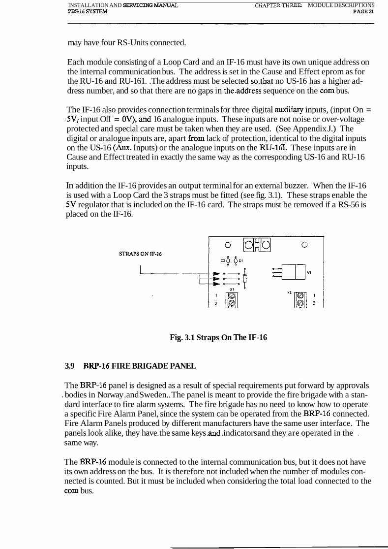
In addition the IF-16 provides an output terminal for an external buzzer. When the IF-16 is used with a Loop Card the 3 straps must be fitted (see fig. 3.1). These straps enable the 5V regulator that is included on the IF-16 card. The straps must be removed if a RS-56 is placed on the IF-16.
Fig. 3.1 Straps On The IF-16
3.9 BRP-16 FIRE BRIGADE PANEL
The BRP-16 panel is designed as a result of special requirements put forward by approvals . bodies in Norway .and Sweden.. The panel is meant to provide the fire brigade with a stan- dard interface to fire alarm systems. The fire brigade has no need to know how to operate a specific Fire Alarm Panel, since the system can be operated from the BRP-16 connected. Fire Alarm Panels produced by different manufacturers have the same user interface. The panels look alike, they have. the same keys .and .indicators. and they are operated in the .
same way.
The BRP-16 module is connected to the internal communication bus, but it does not have its own address on the bus. It is therefore not included when the number of modules con- nected is counted. But it must be included when considering the total load connected to the com bus.

, . . , . ,. . - . INSTALLATION AND SERVICING MANUAL CHAPTER THREE: MODULE DESCRIPTIONS
PS16 SYSI'Eh4 PAGE 22
Two versions of the panel exists. One version has a 2 X 40 character Message Display , .. . similar to the PS-16 Message Display. The other version has a four-digit seven-segment
Address Display fitted instead of the Message Display. The Address Display is similar to the one included on the PS-16.
The panel has a lock and three keys which are.used.to operatethe panel. The BRP-16 can only be operated after it has been unlocked by using a special Fire Brigade key. The panel also has a number of LEDs that indicate the system status.
1;. '-:. INSTALLATION AND SERVICING MANUAL . CHAPTER FOUR: CARD DESCRIPTIONS PS16 SYSTEM PAGE W
CHAPTER FOUR
CARD DESCRIPTIONS
CONTENTS
4.1 PBS16SA LOOP CARD
4.2 COM-16 COMMUNICATION CARD
4.3 IF-16 INTERFACE CARD
4.4 RS-56 OUTPUT DRIVER CARD
4.5 RS-32 ZONE INDICATION CARD

' .,' "RJSTALLA~ON AND SERVICING MANUAL CHAPTER FOUR CARD DESCRIPTIONS PS16 SYSl'EM PAGE 24
CHAPTER FOUR
CARD DESCRIPTIONS
This chapter describes some of the electronic cards used in the PBS-16 system.
4.1 PBS16SA LOOP CARD
The Loop Card is a plug-in card containing a microprocessor, memory and a number of input and output channels. The card is used to control US-16, RU-16 and RU-161 modules as well as Mimic Panels. .The US-16, RU-16 and RU-161 each have a slot reserved for the Loop Card. In Mimic Panels the Loop Card is normally used together with the IF-16 card which provides a plug-in slot and connection terminals.
The Loop Card's microprocessor have an internal EPROM which carries the main soft- ware programme. There is two main types of..core: software .(main.software programme):
(a) For Loop Card controlling a US-16 module.
(b) For Loop Card controlling a Relay Unit or Mimic Panel.
The markings on the processor indicates what type of software is included in it. Refer to Appendix H for information on Loop Card microprocessor markings.
The Loop Card has the following input and output capabilities:
16 Switchable 24VDC output lines 16 Analogue input lines 10 Switchable 5VDC input/output lines 1 Optically isolated communication channel
Which of these input and output lines are available and what they are used for depends on the type of core software fitted, and which type of module it is used with.
The Loop Card also has a socket marked V4 which is reserved fora special Cause and Effect programme. The Cause and Effect programme may modify the Loop Card's re- sponse to fire alarms, fault messages, local inputs or messages it receives via the internal communication bus. A Cause and Effect programme is usually included to meet special requests put forward by the customer. The function of the Cause and Effect fitted on Loop Cards in a specific system is specified in the Operator's Manual Part 2.

... ,.. .' INSTALLATION AND SERVICING MANUAL CHAFTER FOUR: CARD DESCRVITONS PS16 S Y m PAGE 25
A Loop Card used in a PBS-16 or US-16 module does not need to have a Cause and Effect programme fitted to operate. The general rule is that all Loop Cards controlling Relay Units or modules with RS-Units connected require a Cause and Effect EPROM.
4.2 COM-16 COMMUNICATION CARD
L The COM-16 card is a plug-in card. A slot is provided on the US-16 motherboard for the a insertion of a COM-16 card. This slot may only be used if a PS-16 module is directly con- nected to the motherboard. Hence, the COM-16 card may only be used with the PBS-16 module. The reason for this is that the Com-16 card is actually controlled by the micro-
processor included on the PS-16 card. The control signals are passed from the PS-16 mod- ule to the COM-16 card through the 40-way ribbon cable. The PS-16 module must be connected to the motherboard through the ribbon cable and the maximum total length of the ribbon cable allowed is 2 metres.
.-.. ..The most common reason for including a COM-16 card is that a printer is required in the - system.. Other reasons is that communication with other peripheral equipment or other
PBS-16 systems is necessary.
The COM-16 card provides two communication ports. Port one is always configured as RS-232C. Port two may be configured as:
RS-232C, RS-485,
or 20 rnA current loop.
The communication speed (Baud rate), and the configuration of port two is selected by using the three DIP-switches included on the card. Appendix E explains how to set up the Communication Card.
Since the Communication Card is controlled by the PS-16 module will the PS-16 core software determine which port configurations may be used for port two and what informa- tion is sent to the two ports. The Baud Rates selected for the ports are dependent.on the equipment connected.
L 4.3 IF-16 INTERFACE CARD
The IF-16 card is used as an interface card for the PBS16SA Loop Card and the RS-56 Output Driver Card. It consists of a slot for. plugging in a.Loop Card or a RS-56 and two wire terminal blocks. It -also-has a 5VDC regulator.:which.isrenabled when the straps di- rectly above connection terminal X1 is included.
The 5VDC regulator must be enabled when it is used with a Loop Card since the Loop Card does not have its own 5V regulator. The straps enabling the 5VDC regulator must be removed before it is used with a RS-56.

. . : ' "C I .INSTALLATION AND SERVICING MANUAL CHAPER FOUR: CARD DESCRIF'TIONS
PS16 SYSTEM PAGE 26
Appendix J shows which function each of the connection terminals have when the IF-16 is used with the Loop Card or the RS-56.
4.4 RS-56 OUTPUT DRIVER CARD
This is a Relay Slave Unit or .Relay Expansion Unit. - It has 56 switchable 24VDC outputs. The RS-56 card is similar in size and shape to the PBS16SA Loop Card, and it is usually .
:-..used together with the IF-16 Interface Card.
The IF-16's 5VDC regulator must be disabled when used together with the RS-56. The .:-.. -: regulator is disabled when the three strapslocated directly above terminal block X1 is cut
or not fitted at all.
. The RS-56 has no microprocessor itself, and is always used together with a Loop Card B -. which controls the 56 outputs. How many RS-56 can be controlled by a single Loop Card is
I dependent on the type of core software included in its microprocessor. A Loop Card in a US-16 may only control one RS-56 while a Loop Card fitted with RU-16 software may control up to four RS-56. The combination of one Loop Card and four RS-56 gives a maximum of 240 outputs that can be controlled by a single Loop Card.
Primary uses of the RS-56 is to drive lamps on Mimic Panels or relays.
4.5 RS-32 ZONE INDICATION CARD
. , ,, The RS-32 has 32 red LEDs. The outputs are controlled by the processor on a Loop Card. The RS-32 is normally used together with the PBS-16 module to give zone indication for
. . ..fire alarms in the system. It is then connected to the terminals provided on the US-16 motherboard for the connection of a RS-Unit.
In some countries it is mandatory that a RS-32 is included with the PBS-16 module to give zone indication.
The RS-32 may also be connected to Relay Units or Loop Cards placed on IF-16 Interface Cards.

. . . . .. . . . . .i . - . ;':' FKIXLLAT'ION AND SERVICING MANUAL CHAPTER FIVE: INSTALLATION
PBSl6 SYSTEM PAGE 27
CHAPTER FlVE
INSTALLATION
5.1 GENERAL 5.1.1 Mechanical Installation 5.1.2 . . Electrical Installation
5.2 POWER SUPPLIES 5.2.1 . . . . Disable Supply Monitoring
5.3 INPUTS 5.3.1 Short Circuit Isolators 5.3.2 Conventional Detectors 5.3.3 Addressable Sensors 5.3.3.1 AnalogueSystem 5.3.3.2 Digital System 5.3.4 Auxiliary Inputs
5.4 OUTPUTS 5.4.1 Sounders 5.4.2 Control Relay Outputs And The Fault Alarm Relay 5.4.3 24V DC Outputs 5.4.4 Fault Output (Total Power Failure) 5.4.5 RS Unit Connections
TABLES
Table
5.1 Recommended Cabling 5.2 Line Connections at X3 5.3 Loop Connections at X3 5.4 Auxiliary Inputs 5.5 Relay Output Connections

.t ,.- . ' LNSTALLATION AND SERVICING MANUAL CHAPTER- INSTALLATION PS16 SYSIEM PAGE 31
5.2 POWER SUPPLIES
Power supplies to a PBS-16 system may be centralised or distributed. That is, there may be one Charger Unit and battery supplying one PBS-16 module with 24V DC, from which all other modules are supplied (centralised), or each'PBS-16 aid .US-16 module may have its . .
. own Charger Unit and battery (distributed); and distribute.:its.supply to other local mod-. ules.
CAUTION!
FULL MAINS VOLTAGE MAY BE PRESENT WITHIN ' THE CHARGER UNIT. DISCONNECT THE MAINS
WHILE SERVICING THE CHARGER UNIT FOR MAXIMUM SECURITY.
At the Installation stage, although cables must be run to the mains supply and correctly terminated, they must remain isolated from the supply.. Wiring must be taken to the 24V . . DC batteries and terminated correctly for the batteries, but -the connections to the batteries must not be made. There must be no way in which mains or battery.co~ections could be made accidentally.
The 24V DC supply wiring from the Charger Unit goes to a PBS-16 or US-16 module and is distributed from there to other modules. Although the wiring is to be installed and correctly terminated, the connections into modules from the PBS-16 or US-16 are not to be made. Instead, they are to be temporarily insulated. .
Where the 24V DC supply cables are connected (that is, battery cable into Charger Unit, battery supply cable between Charger Unit and PBS-16 or US-16, mains-derived 24V DC supply cable between Charger Unit and PBS-16 or US-16), great care must be taken to ensure that the correct polarity is observed. There can be no reverse polarity protection, and damage can result from a reversed connection.
5.2.1 Disable Supply Monitoring
. - r . : :. A PBS-16 or US-16 that isconnected to a Charger Unit monitors the supply. Other PBS-16 . and US-16 modules are to have their monitoring disabled. .
The procedure is:
(a) On the motherboard of the PBS-16 or US-16, remove the test load PTC resis- . tors R52 and R71. These two resistors are located directly below relay W.
(b) Make a connection from terminal X1/4 to terminal X2/1.

.' -' L l . ~ ~ ~ ~ ~ ~ ~ ~ ~ ~ ~ AND SERVICING MANUAL C ~ R FIVE INSTALLATION PS16 SYSIEM PAGE 32
5.3 INPUTS
Any one PBS-16 or US-16 module may have lines or loops of conventional detectors con- nected to it, or it may have lines or loops of addressable sensors connected to it. It may not have both. However, within one system, one PBS-16 or.US-16 mayihave conventional . .
detectors connected while another has addressable. sensors connected.
NOTE: . All line and loop wiring is polarised and must be kept floating with respect to ,.. the power supply and system earth.
A line has one end of its pair of wires connected to terminal block X3 on the PBS-16 or ;: US-16. : The line length is limited to 1000 metres maximum. That -is, lOOOm for each of the
: wires in the pair.. Or .in other .words a maximum of 1000 metres from, say, the positive . . terminal on the US-16 module to the positive terminal on the device furthest away from
-... the module. Connections are as shown in Table 5.2.
A loop has both ends of the pair of wires connected to the terminal block X3. The loop a length is limited to 1000 metres. That is, 1000 metres for each wire in the pair of wires. Or in other words, a maximum of 1000 metres from, say, the positive terminal on one end of the loop to the positive terminal on the other end of the loop. Connections are as shown in . Table 5.3.
5.3.1 Short Circuit Isolators
Up to a maximum of three short circuit isolators may be installed in any loop. These divide the loop up into four sections, and have the effect of limiting the number of detectors or
. sensors put out of service by a short circuit on the loop.
This unit has connection terminals for connection of an LED which operates when the units reacts to a short circuit on the loop. I£ a LED is not fitted a short circuit connection must be made between those two terminals.
Recommended cabling data is given in Table 5.1.
5.3.2 Conventional Detectors
Up to 32 conventional, that is, non-addressable detectors, may be connected to one line or ... .: : .:loop. ...T he types used are restricted to:
(a) Nittan NID58 Series
' (b) BRK 1800EC
. . (c) Cerberus F712
For a line, the end of line device is normally a 3.9 kohm resistor.

... I I V J ~ A L L A ~ ~ U N AND SkKVICING MANUAL CHAPTER FIVE: INSTALLATION PS16 SYSEh4 PAGE 28
ILLUSTRATIONS
Figure
5.1 Auxiliary Inputs 5.2 Sounder Output Connections 5.3 RS-16 Connection Details 5.4 RS-32 Connection Details 5.5 - RS-56 Connection Details
-' ': INSTALLAT~~N AND SERVICING MANUAL CHAPTER FIVE MSTALLATION PS16 SYSIEM PAGE 29
CHAPTER Fn7E
INSTALLATION . . -
5.1 GENERAL
5.1.1 Mechanical Installation
Mechanical Installation is to be in accordance with the installation drawings included in the . special-to-installation document package. Any deviation from these must be by approved
concession and a record must be kept on or with the installation drawings.
5.1.2 Electrical Installation
Electrical installation, that is, installing and connecting up cables must be in accordance with the detailed wiring information given in the special-to- installation document package. Any deviation from-this must be by approved modification and a record must be kept on:or with the wiring information. The record must be in suffi- cient detail for drawings and wiring schedules to be amended.
All work must be to the quality required by Company Standards, or as required by the standards specified in the special-to-installation data package.
All units, racks, or other enclosures of system equipment, including junction boxes must be connected by suitable conductors to a proper electrical earth. This is to provide protection from electrical interference and static discharges.
For the same reason, particular attention should be paid to ensure that the connection of screens on cables is in accordance with the drawings.
Suitable cabling for each part of the installation is specified in the special-to-installation . . data package, but is summarised here. See Table 5.1 for recommended cabling.

-.* . v - - . . .INSTALLATION AND SERVICLNG MANUAL CHAF'TE,R FFE INSTALLATION
PS16 SYSTEM PAGE 30
Table 5.1 Recommended Cabling
1 RS-485 bus I * * System specific design * * I
CONNECTION
Detection lines or loops
Charger and battery
Power supply monitor- ing
Sounders
Relays
Auxiliary inputs
24VDC aux. outputs
System com. bus
COM-16 card
Note 1: Dependent on the load characterisitcs of the devices used. The sections shown in these cases are indicative only.
. Note 2: : Maximum impedance refers to the total length of wire, i.e. the pair multiplied . - by two, but.maximum capacitance refers to the total length of the pair. . . .
Note that the wire section for the power supply input terminals on the US-16 motherboard is maximum 4mm2. All other.terminals are for maximurn.2.5 mm2::::.:.
CAPACITANCE uF max
1
LENGTH m. max
1000
SECTION mm2 min.
.8 (rigid) l (stranded)
* * For maximum 0.5V drop at full load * *
IMPEDANCE ohms m m
80
20 (Note 2)
n/a
Note 1
Note 1
n/a
Note 1
4000
15
1
1.5
1.5
1
1.5
1.7 (screened)
.6 (Score screened)

I .
: ' .. ;"~'INSTAUATlONAND SERVICING MANUAL CHAPTER FIVE INSTALLATION PBSM SYSEM PAGE 33
Table 5.2 Line Connections Table 5.3 Loop Connections
I -Loop Connections at X3 I
I 1 I 1 + (low end) I 2 - 3 2 + (low end) 4 - 5 3 + (low end) 6 - 7 4 + (low end) 8 9 5 + (low end) 10 - 11 6 + (low end) 12 - 13 7 + (low end) 14 - 15 8 + (low end)
1 + (high end)
2 + (high end) 20 2 1 3 + (high end) 22 - 23 4 + (high end) 24 - 25 5 + (high end) 26 - 27 6 + (high end) 28 - 29 7 + (high end) 30 - 3 1 8 + (high end)
NOTE: With more than one US-16 module in the system, the line or loop numbers for . . modules other than the master PBS-16 start at higher numbers. See Appendix I.
. ..+I ..: - INSTALLATION AND SERVICING MANUAL CHAFTER FIVE: INSTALLATION
PBS16 SYSEM PAGE 34
5.33 Addressable Sensors
Address units are connected across each line or loop. Each address unit represents one address. Each address unit has connected to it one or more sensors; all of which are repre- sented by that address. .An address unit may be.in the.base of;a sensor, or it may be in a . .
separate junction box.
5.33.1 . Analogue System
Analogue sensors provide data to an analogue address unit. The analogue address unit, when scanned, produces an output pulse of 20 mA, whose duration indicates the analogue value read by the sensor.
A 12.8111s pulse is the response which is equal to 100% when using function 20. 100% is normally the limit above which the US-16 or PBS-16 interprets the response as a fire alarm.
. - S .- The normal response of an analogue sensor varies a little depending on type and the envi- , ronrnent, but is normally between 30% and 50% when using function 20.
5.3.3.2 Digital System
Conventional sensors provide data to a digital address unit. The digital address unit, when scanned, produces an output pulse whose amplitude indicates the status of the device. A 4.5 mA pulse is the normal response, while a 20 rnA:pulse.xepresents an alarm condition.
5.3.4 Auxiliary Inputs
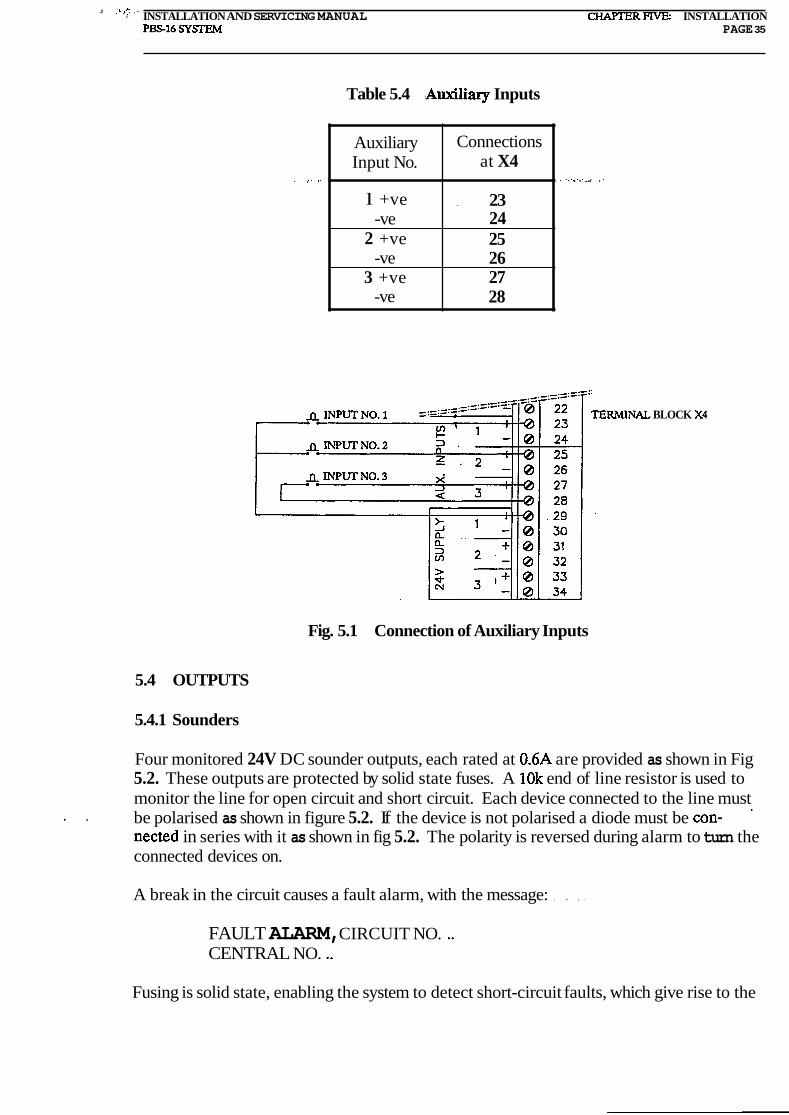
. . _ Three pairs of auxiliaq input terminals are provided as shown in Table 5.4.
- . Inputs number 1 and 2 require an external voltage source. The source may be one of the 24V DC outputs available. Input no. 3 does not require an external voltage source since it is already supplied with 24V DC on terminal 27 from 24V DC output no. 1. Fig. 5.1 shows how the inputs could be connected. The input is activated when the corresponding switch is pressed.
The default programme uses only input number 3. The panel enters the Evacuate mode when this input is activated. The input is activated by putting a short circuit between the input terminals. Inputs number 1 and 2 are disabled in the default programme. Refer to
, . -, :. . Part 2 of the Operator's Manual to find.out how these inputs are used for the particular. - : : -
installation.
Note, however, that terminal 27 gets its voltage through fuse.F3,-(that is the one protecting 24V DC output no. l), and that this input will not.work if fuse F3 is removed or is blown.
.. . .. ... - . Ensure that the correct polarity is observed during wiring.
J :,.. .- S INSTALLATION AND SERVICING MANUAL C H A m R F N E . INSTALLATION
PBS16 SYSTEh4 PAGE 35
Table 5.4 !Auxiliary Inputs
BLOCK
Auxiliary Input No.
l +ve -ve
2 +ve -ve
3 +ve -ve
Fig. 5.1 Connection of Auxiliary Inputs
Connections at X4
. 23 24 25 26 27 28
5.4 OUTPUTS
5.4.1 Sounders
Four monitored 24V DC sounder outputs, each rated at 0.6A are provided as shown in Fig 5.2. These outputs are protected by solid state fuses. A 10k end of line resistor is used to monitor the line for open circuit and short circuit. Each device connected to the line must
. . be polarised as shown in figure 5.2. If the device is not polarised a diode must be con- - nected in series with it as shown in fig 5.2. The polarity is reversed during alarm to turn the connected devices on.
A break in the circuit causes a fault alarm, with the message: . . . .
FAULT ALARM, CIRCUIT NO. .. CENTRAL NO. ..
Fusing is solid state, enabling the system to detect short-circuit faults, which give rise to the

. . ' '; ' : INSTALLATION AND SERVICING MANUAL CHAPTER FIVE: INSTALLATION
PS16 SY- PAGE 36
fault alarm message:
SHORT CIRCUIT ALARM BELL CIRCUIT NO. .. CENTRAL NO. ..
Ensure that the correct polarity is observed for,wiringand for 'diodes.
. . TERMINAL BLOCK X4
X 4
EOL RESISTOR (10 kohm)
4 SOUNDERS - ) ) @ l 8 -. .- .-.-. _._._._
WITH -.-.-.-.-.-._._._. d:9 .L . . . ~ L . - . A .-.- -.-.-._._
POLARISING DIODE
Fig. 5.2 Sounder Output Connections
5.4.2 Control Relay Outputs And The ~ a u l t ~ a h Relay
.. - ..Four sets of voltage free contacts are provided at terminal block 4,- as shown in Table.5.5. Each contact is rated for 2A at 24V DC. - ' . .
The Control Relays (1 to 3) are all normally operated when a fire is detected in the system. The operation of these relays may be modified in cause and Effect programming. Consult the special-to-installation documentation, (Operator's Manual part 2), to find out if the operation of any of these relays have been modified.
The Fault Alarm relay is in the default programme operated when a fault is detected in the system. This relay is normally not energised.
Note that Fault.Alarm Relay is not operated whenever the front panel is indicating a fault . condition by flashing its amber LEDs. A few typical examples of when this relay is not op- erated, (even though the front panels amber LEDs are flashing), are when the system is not initialised, or when something is disconnected.. -.The Fault Alarm relay's operation may be modified in Cause and Effect programming. Consult the special-to-installation documenta- tion to find out if the Fault Alarm relay's operation has been modified.
Note that the three Control Relays may be isolated (in software) by using function 10 from the front panel. The Fault Alarm Relay may not be isolated in the same way, even if it has
j been redefined in Cause and Effect programming. 1

. . .,. L .. .. - .. . . :' INSTALLATION AND SERVICING MANUAL CHAPTER FIVE INSTALLATION PBS-16 SYSIEM PAGE 37
Table 5.5 Relay Output Connections
5.4.3 24V DC Outputs
Three DC outputs, each fused at lA, are provided at terminal block X4, terminals B(+) , 30; 31(+), 32 and 33(+), 34. (See fig. 5.1.)
Note that fuse F3, which is the one protecting DC output no. 1, may blow due to an over- load on terminal 27 (input no. 3) since this output is used to provide power to that input.
A fault warning is given if any one of the fuses is removed or blown. The fault message looks like this:
FAULT POWER FUSE NO. .. CENTRAL NO. ..
5.4.4 Fault Output (Total Power Failure)
Each PBS-16 and US-16 motherboard has an open collector output brought out to terminal block X4, terminals 21 and 22. The transistor opens when the internal panel voltage drops below 15V. The change from short circuit to open circuit signals total power failure.

. . ,. . ... = INSTALLATION AND SERVICING MANUAL CHAFTER FIVE INSTALLATION P S 1 6 SYSTEM PAGE 38
5.4.5 RS-Unit Connections
Each PBS-16 and US-16 motherboard has a pair of connections for an RS Unit. Any one of the RS-16, RS-32 or RS-56 units may be connected. Connection details are shown in Fig 5.3,5.4 and 5.5.
Fig. 5.3 Connection of a RS-16
L----------------------,,---------------------J
Fig. 5.4 Connection of a RS-32
I IF-1 6 WITH .,. I
Fig. 5.5 Connection of a RS-56. (Rs-56 is placed on IF-16 card.)

. . 1
' .'-.INSTALLAnON AND SERVICING MANUAL CHAPTER SIX: COMMISSIONING PS16 SY!XEM PAGE 39
CHAPTER SIX
COMMISSIONING
CONTENTS
INTRODUCTION Inputs Cause and Effect (C&E) and Default Programmes Outputs
RECORD KEEPING
POWER SUPPLIES CONNECTIONS Monitoring
POWER UP
PANEL FUNCTIONS TEST: MANUAL
LxNE/LOOP COMMISSIONING Wiring Checks Electrical Checks Auxiliary Inputs
INITIALISATION Description Initialisation Procedure Testing After Initialisation Completed Input Initialisation
OUTPUTS Sounder Outputs Control Relay Outputs The Fault Alarm Relay Total Power Failure 24V DC Outputs Overall Output Check
BASIC SYSTEM
F . 1':. -! INSTALLATION AND SERVICING MANUAL CHA'PTER SIX: COMMISSIOMNG Pm16 SYSTEM PAGE 40
6.9.1 Message Checking 6.9.2 Cause and Effect Checking
EXTENDED SYSTEM DIP Switches Connections to Internal Bus ,. ..
US-16 Control and Monitor Unit Other Modules Bus Continuity Message Checking Cause and Effect Checking
TABLES Table
6.1 Fault Messages 6.2 Sounder Output Connections 6.3 24V DC Output Connections
ILLUSTRATIONS
Fig
6.1 Charger Unit, Battery, Motherboard Connections 6.2 Corn. Loop Connection Terminals and Bridging Links
. INSTALLATION AND SERVICING MANUAL CHAPTER SEC COMMISSIONING Pm16 SYSEM PAGE 41
CHAPTER SIX
COMMISSIONING' ' '.
6.1 INTRODUCTION
The commissioning process is a gradual build-up, .bringing subsections of the system into working order one by one until a section is complete and functional, and repeating this process for each section. The sections are then brought together into working order, one by one, until the system is complete. An overall functional check of the system is then carried out.
6.1.1 Inputs
Inputs may be lines or loops; devices on these lines or loops may be addressable analogue or digital, or they may be conventional (non-addressable). Separate commissioning proce- dures are given for addressable and conventional inputs. Differences between analogue and digital devices are dealt with as they occur.
6.1.2 Cause and Effect (C&E) and Default Programmes
Each system has a built-in Default programme. That is, in default of (in the absence of) a customised Cause and Effect programme, the system is programmed to give a standard set of responses to inputs.
. - This commissioning procedure is written for the Default Cause and Effect programme, and may be carried out as written. Alternatively, the commissioning procedure may be used with the customised Cause and Effect programme operating. Notes are included in the text to cover differences arising when the customised programme is used.
Where a customised programme has been produced, it is normally installed in the equip- ment at the factory, and commissioning is normally with it in operation.
The Default programme is defined in Appendix A.
6.1.3 Outputs
It may not be desirable for some output devices to be switched repeatedly as system testing . progresses. Thus, for example, once a line of sounders has been proved, it is disconnected
(function 07) until all other output devices have been proved. When all the devices are known to be working correctly, they are all reconnected (functions 08,11), and overall tests are carried out.

'. ' ji INSTALLATION AND SERVICING MANUAL CHAFIER SIX: COMMISSIONING Pm16 SYSTEM PAGE 42
6.2 RECORD KEEPING
Ensure that you keep a full written record of the entire commissioning procedure, including a specification of any problems encountered, and the final system initialisation parameters (i.e. a "map" of the system configuration).
Since a printer is an essential part of the commissioning equipment,-most of this informa- tion is automatically available as hard copy. Information on the connection of a printer to the system is given in Appendix F.
These records should be filed for future reference.
Keep a record describing the system including at least:
(a) Hardware:
: ..:.. .; Types of modules in the system and their addresses on-the internal communication bus.
Address ranges on the detection lines or loops.
Type of sensors and other input devices.
Number.of sounders connected and their types.
Relays and other output devices.
(b) Software:
: . : Core software versions for eachof the modules in the system, including the PS-16 module.
Listing of custom text. If possible a diskette containing a copy of the text file should be kept with the record. The record should also show how the text EPROM is marked, so it is possible to identify which version of the text the EPROM holds.
Listings of the Cause and Effect programme for each sub-unit and how the various EPROMs are marked. Again it would be useful to keep a diskette with copies of the Cause and Effect programmes with the record.
All modifications, extensions, updates etc must be carefully added to the record described above.
NOTE: Software remains the property of Wormald International. The system user is a licensee of this software.

' INSTALLATION AND SERVICING MANUAL CHAPlTR SIX: COMMISSIONING P S 1 6 SYSTEM PAGE 43
6.3 POWER SUPPLY CONNECTIONS (Fig 6.1)
Power supplies to a PBS-16 system may be centralised or distributed. That is, there may be one Charger Unit and battery supplying one PBS-16 module with 24V DC, from which all other modules are supplied (centralised), or each PBS-16 and,US-16 module may have its . own Charger Unit and battery (distributed).
Discover which arrangement applies for the system you are commissioning.
Ensure that the mains input to each Charger Unit is disconnected.
At each PBS-16/US-16 motherboard not associated with a Charger Unit, disable the re- dundant supply monitoring, as follows:
Remove the two PTC resistors R52 and R71 (the test load resistors). They are located just below the relays on the right hand side of the US-16 motherboard.
- . .. Connect .tenninal.X1/4 to terminal.X./l (to disable the mains monitoring).
At each PBS-16/US-16 motherboard associated with a Charger Unit:
Remove the battery fuses F1 and F2.
Disconnect, by unclipping the external part ofthe .terminals;-.all connections to the motherboard terminal blocks X3, X4, X5.
Fit a 10 kohm resistor across each of the four sounders X411 (+,-); X412 (+,-); X413 (+,-); X414 (+,-) to close the sounder monitor circuits during testing.
: .Ensure that the connections are made correctly, as shown in Fig 6.1, between the Charger. Unit, battery, and PBS-16/US-16 motherboard.
Note that the power supply you are using may have terminals marked differently to the markings shown in figure 6.1. Please refer to the installation instructions that accompanied your power supply for further detail.
CAUTION!
BECAUSE THE BATTERY MAY BE ON CHARGE OR DISCHARGE, NO REVERSE POLARITY
PROTECTION IS FITTED.
TO AVOID DAMAGE TO EQUIPMENT, IT IS ESSENTIAL THAT THE CORRECT
POLARITIES ARE OBSERVED.

. . . . . : ' INSTALLATION AND SERVICING MANUAL CHAF'TER SIX: COMMISSIONING
P S 1 6 SYSTEM PAGE 44
Fig. 6.1 Power Supply Unit (Charger Unit) Connections
6.3.1 Monitoring
l 0 I------
Internal I - , connection for ! F- battery
! ! 5 I L . -d
! 6 L.-.-.
POWER SUPPLY (CHARGER UNIT)
8
9
A battery supervision signal is sent from the motherboard via terminal X113 to the Charger Unit, requesting a reduction in voltage to approximately 18V, to check the presence of the battery. This occurs every ten seconds. In addition, every hour a load of approximately 1.5A is applied to the battery to check its charge level. This is via R52 and R71 on the motherboard.. A Battery Fault alarm is given if, during this test, the battery voltage at terminal block X2 falls below 23.6V + /-0.3V.
(+) = ( ) 24VDCBATI'ERY SUPPLY
= m
(-1
(+) <
X
BA'ITERY
(+l 1
(-1 24V DC MAIN SUPPyl P * BATI'ERY CHECK
d
MAINS CHECK
- W 1 (BATI'ERY +)
x2/2' (BATI'ERY -)
PBS-l6
or
US-16
X111 (CHARGER +)
X112 (CHARGER -)
X113 (BA'IT. CON.)
X114 (MAINS CON.) ,
The rectified, smoothed main DC supply (before regulation) is brought to terminal X114 for supervision. A Mains Fault alarm is given if this signal disappears. The presence of a smoothing capacitor in the supply may delay this alarm by up to 30 seconds.
*$
The following procedures should be completed for equipment supplied from one Charger . . . . , .: : Unit before starting on equipment supplied from other charger Units.
6.4 POWERUP
Connect and switch on the supply to the Charger Uqit. Replace the battery fuses F1 and F2. Ensure that the green Mains On lamp is lit at the Control Panel. Silence any alarms and ignore any fault indications on the displays. Use function 18 to set the date and time.
2 .. . .<-INSTALLATION AND SERVICING MANUAL CHAPTER SIX: COMMISSIONING PS16 SY- PAGE 45
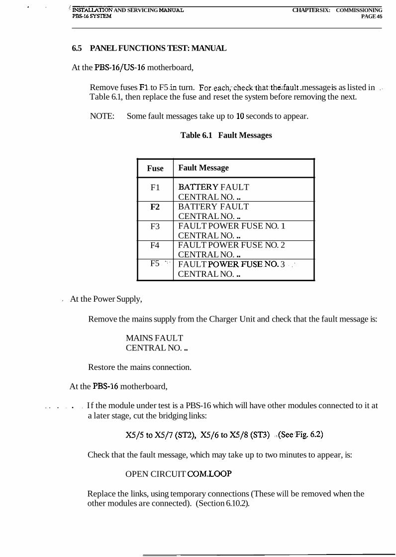
6.5 PANEL FUNCTIONS TEST: MANUAL
At the PBS-16/US-16 motherboard,
Remove fuses F1. to F5 .in turn. For.each;~checkthat:the;;fault .message is as listed in . -
Table 6.1, then replace the fuse and reset the system before removing the next.
NOTE: Some fault messages take up to 10 seconds to appear.
Table 6.1 Fault Messages
.. At the Power Supply,
Remove the mains supply from the Charger Unit and check that the fault message is:
Fuse
F1
F2
F3
F4
F5 - '.'
MAINS FAULT CENTRAL NO. ..
Fault Message
BATTERY FAULT CENTRAL NO. .. BATI'ERY FAULT CENTRAL NO. .. FAULT POWER FUSE NO. 1 CENTRAL NO. .. FAULT POWER FUSE NO. 2 CENTRAL NO. .. FAULT P0WER:FUSE;NO. 3 .. . - :
CENTRAL NO. ..
Restore the mains connection.
At the PBS-16 motherboard,
. . . . . . If the module under test is a PBS-16 which will have other modules connected to it at a later stage, cut the bridging links:
Check that the fault message, which may take up to two minutes to appear, is:
OPEN CIRCUIT COM.LOOP
Replace the links, using temporary connections (These will be removed when the other modules are connected). (Section 6.10.2).
IIIOI-I~UN ANU bCKVIClNCi hl.ANUAL Pm16 SYSTEhf
WAFTER SIX: COMMISSIONING PAGE 46
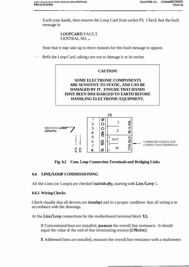
Earth your hands, then remove the Loop Card from socket P3. Check that the fault message is:
LOOPCARD FAULT CENTRAL NO. ..
Note that it may take up to three minutes for this fault message to appear.
. - Refit the Loop Card, taking care not to damage it or its socket.
CAUTION!
SOME ELECTRONIC COMPONENTS , ARE SENSITIVE TO STATIC, AND CAN BE
DAMAGED BY IT. ENSURE THAT HANDS HAVE BEEN DISCHARGED TO EARTH BEFORE
HANDLING ELECTRONIC EQUIPMENT.
BRIDGING LINKS ( W S ) 7
COMMUNICATION LOOP CONNECTION TERMINALS
Fig. 6.2 Com. Loop Connection Terminals and Bridging Links
rq-
6.6 LINE/LOOP COMMISSIONING
1 0 2 3 4
6
8
All the Lines (or Loops) are checked individually, starting with Line/Loop 1. I
6.6.1 Wiring Checks
0 - @ +
0 0 @ @
0 -
Check visually that all devices are installqd and in a proper condition: that all wiring is in accordance with the drawings.
1 i W K X
2 3 a
+ OUT cn 3
IN r 0 o
At the Line/Loop connections for the motherboard terminal block X3,
If Conventional lines are installed, pleasure the overall line resistance. It should equal the value of the end-of-line terminating resistor (3.9kohm).
If Addressed lines are installed, measure the overall line resistance with a multimeter.
INSTALLATION AND SERVICING MANUAL CHAF'TER SIX: COMMISSIONING P S 1 6 S Y m M PAGE 47
Make sure the positive lead from the meter is applied to the positive line terminal. The resistance measured should be relatively high (megohms). A small resistance may indicate a short circuit or address units connected the wrong way around.
Continuity is checked by short-circuiting the positive and negative lead at the far end of the line and then measuring the overall resistance on the line. It should now be close to zero. The maximum impedance allowed is 80 ohms. Remove the short circuit and check that the line resistance has changed to a very high value.
Also with the loop/line disconnected measure the resistance from the positive wire to the 24VDC supply. Check the resistance both to the +24V and OV. (Use either the auxiliary 24V Supply terminals, Battery terminals, or the Charger connection terminals.) The resistance measured should be very high in both cases since the detection loops/lines should be floating with respect to the 24VDC supply.
Also the resistance between the negative wire of the loop/line and the 24VDC terminals should be checked in the same way. Again the resistance should be high.
CAUTION!
MEGGARS MUST NOT BE USED TO CHECK CONTINUITY OR INSULATION
BREAKDOWN WITHOUT FIRST DISCONNECTING ALL ELECTRONIC DEVICES
(DETECTOR BASES, ADDRESS UNITS).
6.6.2 Electrical Checks
If any Fire or Fault alarms appear, take careful written note of the exact wording of the alarm message(s). Investigate and correct the cause of each, dealing with them one by one.
NOTE: One fault may cause several messages, and one fault may cover up others.
For any problems, see Trouble Shooting (Section 6) .
Once any alarms have been corrected, simulate the following fault conditions on the Line or Loop.
(a) Open circuit. This should be made at each end of the Line or Loop, in turn.
(b) Short circuit. Short-circuit each line. On a Loop, where Short Circuit Isolators (SCIs) are fitted, a short circuit should be applied in each section in turn.
In each case, check that the fault is reported on the display and that the correct fault messages are displayed.
INSTALLATION AND SERVICING MANUAL CHAPTER SIX: COMMISSIONING P S 1 6 SYSTEM PAGE 48
Use function 20 (List Detector Values) to check that each address installed is giving a reading in its quiescent state greater than the fault level.
NOTE: Any reading less than 2% on a digital line or loop, or less than 21% on an analogue line or loop causes the address to be ignored during initialisation. Detector responses are detailed in Appendix A of the Operating Manual.
Obtain a printout of a full list of address readings by using function 22 or function 23 (See Operating Manual).
NOTE: It is essential that there is an unbroken sequence of addresses from number 01 to the highest in the line or loop, although they do not need to be in sequential order. Keeping the addresses in sequence on the line or loop has certain advan- tages and should be done as far as possible.
6.6.3 Auxiliary Inputs l
Three pairs of auxiliary input terminals are provided at terminal block X3. In the Default programme, only the third pair, Auxiliary Input 3, at X3127 (+ve) and X3/28(-ve) are functional.
Short-circuit these terminals and listen to hear if the alarm bell relay operates. If sounders are connected to alarm bell circuits 1,2,3, or 4 then these will be turned on.
Remove the short circuit.
The above test may not have the desired effect if a cause and effect program has modified either the relay logic or the auxiliary input logic.
If the customised Cause and Effects programme is in use, discover from its documentation which of the auxiliary inputs are functional, and check them as above.
Figure 5.1 shows how the inputs could be connected.
6.7 INITIALISATION
6.7.1 Description
Before initialisation, the PBS-16 or US-16 module has no information about the devices connected to it. This applies to the input circuits and to modules on the communications 'bus. The system makes the assumption that anything up to the maximum number of input devices and modules may be connected. All alarm signals received are correctly reported, but there is no indication if any devices are missing.
When initialisation takes place, the system creates and stores a map of the installation at that time. This provides a reference so that the absence of a response from a device indi- cated on the map creates an alarm.

INSTALLATION AND SERVICING MANUAL CHAPTER SIX: COMMISSIONING P S 1 6 SYSXEM PAGE 49
If further lines/loops or devices are added after initialisation, the system does not recog- nise them, and re-initialisation is necessary for them to be included on the map. There is one exception to this:
An alarm device with an address one higher than the highest initialised address is moni- tored for fire alarm (but not for fault alarm). This exception is to facilitate the testing of small modifications to the system before re-initialising.
NOTE: Initialisation only includes in the system map those devices giving a response greater than or equal to 2% (digital systems), or greater than 20% (analogue systems).
6.7.2 Initialisation Procedure
As each line or loop is connected and found correct, the system is initialised. The system is re-initialised when the next line or loop is added, and so on until all the lines or loops have been connected and initialised. Between each time the panel is initialised, its previous initialisation parameters must be cleared either by using Function 34 or by disconnecting the power supply.
Before initialisation begins, the system must be in the quiescent state.
At the Printer,
Ensure that the printer is connected and ready to print.
At the Control Panel,
Use function 30 (Initialise All Uninitialised Parts of the System). The system responds with a request for a special access code. When this is entered,'initialisation starts. The printer prints out the message:
Date Time INITIATION STARTED
Initialisation takes up to five minutes, and during this time the system must not be touched. If the PBSVIEW servicing and commissioning tool is connected it must not be in the Auto Update mode. Preferably it should be in the Message mode, or disconnected altogether. Any fire alarm occurring during this period overrides the initialisation sequence, which must then be restarted when the system is again quiescent.
Upon completion of initialisation, the module performs an automatic system reset (only the green Mains On lamp is lit). The printer prints out the message: . .
Date Time RESET ALARM Date Time * *INITIATION FINISHED* *
.Function 31 produces a printout of the list of initialised devices and units, and constitutes a \
INSTALLATION AND SERVICING MANUAL CHAPTER SIX: COMMISSIONING PBS-16 S Y m M PAGE 50
complete specification of the configuration of the system. This may be compared at any time with the printout obtained from function 16 (Search Faults), as a check for deviations.
6.7.3 Testing After Initialisation
When a line or loop has been initialised, carry out the following tests:
(a) Check the response of the highest address. If this is present, all the others must be.
(b) Make a random check for a fire alarm or fault alarm by (for example) unplugging an input device.
When the next line or loop is connected and the system is quiescent, carry out the initialisa- tion procedure again. Make sure all previous initialisation parameters have been cleared either by using function 34 or by disconnecting the power supply.
Repeat this until all lines or loops are initialised.
6.7.4 Completed Input Initialisation
When all lines or loops are initialised, carry out tests using Disconnect Loop (function 4) and Reconnect Loop (function 5).
Use function 4 to disconnect each line or loop in turn. The line or loop voltage is still present. Only alarm messages related to detector alarms are blocked off, so a fire alarm created on the loop is ignored by the panel. The scanning of the loop or line and updating of the detector value registers continues as normal. This means that the servicing and commissioning tool PBSVIEW is able to check detectors even on disconnected loops or lines.
Use function 6 to get a list of disconnected loops.
Messages relating to overload and short circuit are not blocked when a loop or line is disconnected.
Use function 5 to reconnect each line or loop in turn. Check that fault or fire alarms come through from the reconnected line or loop.
Carry out tests using Disconnect Detector (function 1) and Reconnect Detector (func- tion 2).
Use function 1 to disconnect randomly selected devices on the various lines or loops. Cre- ate a fault or fire alarm at each of the devices disconnected. There should be no response from the system. You may not use PBSVIEW to simulate a fire or fault on the discon- nected devices. The test may be performed by removing the detector head or by injecting test gas into the detector head.
\
Use function 3 to get a list of disconnected devices.
INSTALLATION AND SERVICING MANUAL CHAPTER SIX: COMMISSIONING PS16 SYSEM PAGE 51
Use function 2 to reconnect the devices. Check that alarms from the reconnected devices come through.
6.8 OUTPUTS
6.8.1 Sounder Outputs
There are four separate sounder outputs from the PBS-16 module. In turn, for the circuit to be connected to each, carry out the following procedure.
Check visually that all devices are installed and in a proper condition.
Check that all wiring is in accordance with the drawings.
CAUTION!
MEGGARS MUST NOT BE USED TO CHECK CONTINUITY OR INSULATION BREAKDOWN.
WITHOUT FIRST DISCONNECTING ALL ELECTRONIC DEVICES (ALARM SOUNDERS).
Check that all devices are correctly polarised and fitted with a correctly polarised external diode if necessary. Also check that all four alarm bell circuits are fitted with a 10kohm EOL resistor.
For any problems, see Trouble Shooting (Chapter 7).
When the wiring is correct, connect the cable to its terminals on Terminal Block X4, ensur- ing that the correct polarity is observed. See Table 6.2 for connections.
The four alarm bell circuits (sounder outputs) are monitored for open and short circuit, and the messages described in section 6.4.1 are displayed in the PS-16 Message Display upon the detection of a fault on the alarm bell outputs.
The outputs are protected by a solid state fuse and each output is rated at 0.6A resistive. ... load.
Inject a fire alarm at Auxiliary Input 3 by connecting a short circuit between terminals X4127 and X4/28.
NOTE: This is valid for the Default programme. For the customised programme, find a suitable fire alarm input from its documentation. The alarm may be injected by the PBSVIEW servicing and commissioning tool if it is connected.
Check that all sounders on the circuit operate.

INSTAUATION AND SERVICING MANUAL CHAF'TER SIX: COMMISSIONING PS16 SYSl734 PAGE 52
Remove the short circuit.
Use function 07 to disconnect the sounder circuit. Use function 09 to check which sounder circuits are disconnected.
Check that the disconnected sounder circuits do not operate when a fire alarm is injected as described earlier.
Repeat the above procedure for each sounder circuit.
Reconnect the sounder circuits by using function 08.
Table 6.2 Sounder Output Connections
6.8.2 Control Relay Outputs
Sounder Output No.
l +ve -ve
2 +ve -ve
3 +ve -ve
4 +ve -ve
Under the Default programme:
Terminal Block X4 Connector No.
1 2 3 4 5 6 7 8
(a) Simulate a fire alarm either by using PBSVIEW or by operating a manual call point connected to one if the detector loop inputs.
(b) All three control relay outputs are operated by this input.
For the customised programme, find suitable fire alarm inputs from its documentation to operate the control relay outputs. The alarm may be injected by the PBSVIEW servicing and commissioning tool if it is connected.
Record the alarm inputs used.
Check visually that all devices are installed and in a proper condition.
\ Check that all wiring is in accordance with the drawings and with the specification.
.. / .
INSTALLATION AND SERVICING MAKUAL CHAPTER SIX: COMMISSIONkiG P S 1 6 SYSIBA PAGE 53
Carry out the following procedure for each of the three output circuits in turn.
When the wiring is correct, connect the cable to its terminals on Terminal Block X4. See Table 5.5 for connections.
Inject an alarm and check that the circuit operates correctly.
Disconnect the alarm.
Use function 10 to disconnect the circuit.
Repeat the above procedure for each of the relay circuits.
Use function 12 to check which control relay outputs are disconnected, and use function 11 to reconnect these after the test is completed.
6.8.3 The Fault Alarm Relay
Under the default programme:
(a) Make a fault by removing one of the 24V supply fuses (F3, F4 or F5).
(b) Check that the Fault Alarm relay operates.
For the customised programme:
(a) Find a suitable input from the cutomised programmme's documentation, and simu- late this input.
(b) Check that the relay operates.
Record the alarm inputs used.
Check visually that all devices are installed and in a proper condition.
Check that all wiring is in accordance with the drawings and with the specification. When the wiring is correct, connect the cable to its terminals on Terminal Block X4. See Table 5.5 for connections.
Cause the relay to operate by simulating a suitable input, and check that the circuit oper- ates correctly.
6.8.4 Total Power Failure
Check visually that all devices are installed and in a proper condition.
Check that all wiring is in accordance with the drawings and with the specification.
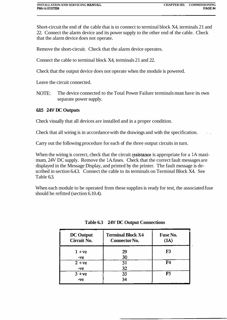
INSTALLATION AND SERVICING MANUAL CHAPTER SIX: COMMISSIONING Pm16 SYSTEM PAGE 53
Short-circuit the end of the cable that is to connect to terminal block X4, terminals 21 and 22. Connect the alarm device and its power supply to the other end of the cable. Check that the alarm device does not operate.
Remove the short-circuit. Check that the alarm device operates.
Connect the cable to terminal block X4, terminals 21 and 22.
Check that the output device does not operate when the module is powered.
Leave the circuit connected.
NOTE: The device connected to the Total Power Failure terminals must have its own separate power supply.
6.8.5 24V DC Outputs
Check visually that all devices are installed and in a proper condition.
Check that all wiring is in accordance with the drawings and with the specification. .. .
Carry out the following procedure for each of the three output circuits in turn.
When the wiring is correct, check that the circuit r,esistance is appropriate for a 1A maxi- mum, 24V DC supply. Remove the 1A fuses. Check that the correct fault messages are displayed in the Message Display, and printed by the printer. The fault message is de- scribed in section 6.4.3. Connect the cable to its terminals on Terminal Block X4. See Table 6.3.
When each module to be operated from these supplies is ready for test, the associated fuse should be refitted (section 6.10.4).
Table 6.3 24V DC Output Connections
I DC Output Terminal Block X4 Fuse No. Circuit No. Connector No. I
INSTALLATION AND SERVICING MAhUAL CHAPTER SIX. COMMISSIONING P S 1 6 SYSEM PAGE 55
6.8.6 Overall Output Check
When all the output circuits have been checked individually and found to be correct, recon- nect the 24V DC Output terminals on terminal block X4, ensuring that each circuit is connected to its correct terminals, and that the correct polarity is observed.
Use function 14 to reconnect all currently disconnected lines or loops, detectors, sounder circuits and the control relay outputs.
The panel should now be reset. Wait a little while to make sure that no fault messages relating to the outputs comes through.
Inject an alarm and check that all circuits operate correctly.
Where a customised Cause and Effect programme is in use, select and inject alarms to check that all output circuits operate correctly.
6.9 BASIC SYSTEM
All parts of the system operating from the single PBS-16 or US-16 module have been tested at this stage. It remains to reinitialise the system, and to carry out a detailed check of the system messages and of the cause and effect responses.
Detailed records must be kept. See section 6.2.
Most of the records required may be obtained as printouts from the system.
When all connected circuits have been found correct, initialise the system as described in section 6.7.2.
6.9.1 Message Checking
It is mandatory that an alarm is simulated at every input address. For each alarm, check that the Message Display shows the correct message, as listed in the customised system data.
6.9.2 Cause and Effect Checking
Use function 14 to reconnect all currently disconnected lines or loops, detectors, sounder circuits and control relays.
It is mandatory that all the relevant causes in the system are simulated. For each, check that the correct effects are being produced in all the output circuits and devices.
For a system which has the PBS-16 module, but no extension modules, commissioning is now complete. Records should also be completed (section 6.2).
For systems that have additional modules, refer to section 6.10.
INSTALLATION AND SERVICING ,MANUAL CHAFTER SIX: COMMISSIONING PS16 SYSIEM PAGE 56
6.10 EXTENDED SYSTEM
For extended systems, the next stages are to test the remaining modules in isolation, then connect them, one by one, through the internal system communications bus to the Master PBS-16, initialise the complete system and run an overall test. The system is then ready for a thorough check and recording of its performance.
6.10.1 ' DIP Switches
Each module including a Loop Card must have its own unique address on the internal communication bus. The address is either set on a DIP switch included on the US-16 motherboard or in the Cause and Effect EPROM. The addresses allocated form a continu- ous sequence from 01 upwards, and are to be found in the customised documentation package. Coding for setting the DIP switches is given in Appendix C.
6.10.2 Connections to Internal Bus
For connection to the bus, each module has a pair of wires entering and a pair of wires leaving the module. The wires are linked inside the module, providing continuity for the bus, only if the module is connected. Because connected addresses must be in an unbroken sequence, the first module to be added to the bus must have the address 02.
During commissioning of the master PBS-16, the internal bus has been disconnected at terminal block X515 to 8. Before starting to commission any other modules, disconnect them all from the bus.
At the master PBS-16,
Set the DIP switch to its correct address (normally 01). Connect the bus to terminal block W / 5 to 8.
If all modules are connected to the communication bus and a complete loop have been formed, disconnect the temporary links 5 to 7,6 to 8, on terminal block W that were fitted at para 6.5. This enables two-way monitoring of the bus. A break will not be detected if the links are not removed. The links must therefore not be removed until the communication bus forms a complete loop.
When each module has been tested in isolation, it is ready for connection to the bus. Be-. fore it is connected, set its DIP switch to the correct address for the module.
When one module has been connected to the bus, it should be fully commissioned and initialised before the next module is connected.

MSTALLATION AND SERVICING MANUAL CHAFER SIX: COMMISSIONING PS16 SYSTE3M PAGE 57
6.10.3 US-16 Control and Monitor Unit
Carry out the procedures given in para 6.3 and 6.4, that is, Power Supplies Connections, and Power Up.
Use one of the following two methods to continue testing:
(a) Test the US-16 as a completely autonomous alarm system with a PS-16 Information and Control Panel connected. PBSVIEW (Appendix B) may also be connected in addition to the PS-16 panel.
(b) Connect the internal system communications bus (para 6.10.2) to use the facilities of the PBS-16 already commissioned.
In either case, the continued checking and commissioning of the US-16 is as already de- scribed.
Repeat this procedure for each PBS-16 and US-16 when its turn for commissioning is reached.
6.10.4 Other Modules
All modules except for the PBS-16 and US-16, receive their power supplies from either a PBS-16 or a US-16. The only exceptions are RS-Units which may get their power via a RU-161. For each module to be commissioned, connect the 24V DC power supply from its parent module, ensuring first that there are no other connections to the module, and ensur- ing that the supply polarity is correct.
Cany out tests on the module in isolation. These tests are specified for the modules in Appendix D.
Connect each module, in its address sequence, to the bus and check that it produces the correct responses. Relay Slave Units (RS-16, RS-32, RS-56) should be added to the parent Relay Unit or US-16 module and checked as soon as it has been commissioned. Each time commissioning has been completed on one module, the system should be re- initialised.
6.10.5 Bus continuity
Because the internal bus can continue to function with a break in it, it is necessary to check that the bus is complete. When all modules have been connected, short circuit one end of the bus at the master PBS-16 and measure the resistance of the bus from the other end. Its value should be close to 0 ohm. The maximum impedance allowed is 20 ohms.

INSTALLATION AND SERVICING MANUAL CHAPTER SIX: COMMISSIONING PS16 SYSJEM PAGE 58
CAUTION!
MEGGARS OR OTHER HIGH-VOLTAGE INSTRUMENTS MUST NOT BE USED.
6.10.6 Message Checking
It is mandatory that an alarm is simulated at every input address. For each alarm, check that the Message Display shows the correct message, as listed in the customised system data.
6.10.7 Cause and Effect Checking
Use function 14 to reconnect all currently disconnected lines or loops, detectors, sounder circuits and the control relays.
It is mandatory that all the relevant causes in the system are simulated. For each, check that the correct effects are being produced in all the output circuits and devices.
Commissioning is now complete. Records should also be completed (section 6.2).
USI"LLATI0N AND SERVICIKG MANUAL CHAPTER SEVEN: SERVICING PS16 SYSTEM PAGE 59
CHAPTER SEVEN
SERVICING
CONTENTS
AUTOMATIC MONITORING False Alarm Reduction Fault Alarms System Data
ROUTINE SERVICING
TROUBLE SHOOTING The PS-16 Card Is 'Dead' No Power At The US-16 Motherboard Loop Card Fault The COM-16 Communication Card Does Not Work RS-Units (RS-16, RS-32, RS-56) Do Not Work Open Circuit On The Communication Loop Is Not Detected Open Circuit On Alarm Bell Circuits Short Circuit On Alarm Bell Circuit Open Circuit On Detection Loops Or Lines Earth Fault No Response From Address Units Or Detectors
TROUBLE SHOOTING - QUICK REFERENCE
TABLES
Table
7.1 Quick Reference Table

INSTALLATION AND SERVICING MPuiAL CHAPTER SEVEN: SERVICLhJG PS16 SY!3Eh4 PAGE M)
CHAPTER SEVEN
SERVICING
7.1 AUTOMATIC MONITORING
The PBS-16 system is self monitoring. Power supplies are monitored: a no-volt alarm is provided if they fall below acceptable levels, and separate alarms are provided if output supplies fail. The microprocessor control and display circuits are self-tested every two seconds, and provide a system fault alarm if they fail.
When the system has been set up and is initialised, it creates and stores a map of the instal- lation at that time. This provides a reference so that absence of response from a device indicated on the map creates an alarm. It also provides a reference level for each alarm device, so that it may define fault alarm and fire alarm thresholds for each input, and re- spond accordingly.
7.1.1 False Alarm Reduction
A comparison of actual signal level with the reference level is made automatically every 24 hours for each device, and if a drift in value is noted, a partial correction is made to the stored reference value. Too much correction could result in an alarm condition being missed: too little correction, and a drift in sensor response with time could result in a false alarm. A balance is achieved to minimise the false alarm rate without jeopardising the genuine alarm signal.
Note that this feature only applies to systems using analogue sensors.
7.1.2 Fault Alarms
When a fault alarm is produced, a message is displayed on the PBS-16 Message Display, indicating the nature of the fault. If a Printer is connected, the message is also printed out. By use of the functions available from the keypad more information can be obtained. Most of these functions are described in the PBS-16 Operators Manual. Others, which are serv-- .. icing functions only, are described in Appendix G of this manual.
7.1.3 System Data
Information necessary for servicing the system is largely contained in this manual.
Customised and special-to-installation data is contained in the separate documentation package for the system.
INSTALLATION AND SERVICING MANUAL CHAFI'ER SEVEN: SERVICING PBS-16 SYSTEhl PAGE 61
7.2 ROUTINE SERVICING
On a large installation, the number of sensors can run into many thousands, so it is an enormous advantage that routine monitoring of all devices is performed approximately every two seconds. Printouts of the results of the monitoring should be made, checked and . - . filed by the s e ~ c e engineer on a regular basis. This provides records against which the system can be checked if or when a fault condition does occur.
7.3 TROUBLE SHOOTING
This section is not meant as a complete guide to all problems that may arise with a PBS-16 system during installation, commissioning, servicing or normal operation. The purpose of this section is to give a few ideas of what to do when certain things happen, and hopefully to help you search for the cause of the problem in a structured and efficient way.
Very often the PBS-16 system itself will give the engineer or technician working with the installation a good indication of what the problem is. The engineer or technician should, however, remember that the accuracy of the fault messages displayed in the PS-16 Message Display is dependent on how 'Standard' the installation-is. For example, the panel will .. - . .
always assume that the address units on the detector loops or lines are physically placed in sequence. If this is not the case for your installation, fault messages regarding faults on the lines or loops may not be accurate.
It is very important that the cause of the fault is found and cured. Sometimes it is easier to remove the symptom of the problem, than it is to actually put the fault right. But when this is done, the fault is still there, even though the fault message never appears because the symptom has been cured. This puts the proper and safe operation of the system at risk.
A typical example of this problem is to disconnect the earth lead on the US-16 mother- board from the cabinet. This disables monitoring of earth fault, and the panel is not able to detect such a fault. This action does not cure the problem, but merely removes the panel's ability to see the fault. The earth fault is still there and may cause more problems in the future.
Below you will find a number of problems listed and suggestions of what can be wrong, and what to do to rectify the problem.
7.3.1 The PS-16 Card Is 'Deady
Symptom:
Message Display shows nothing and all LEDs are off. No sound is heard when push- ing a key on the keypad. No lights come on when the lamp test button is pressed. It is not possible to receive or send any messages on the communication bus when PBSVIEW is used.
LUSTALLATION AND SERVICISG .%JUAL CHAPTER SEVEN: SERVICING PBS-16 SYSEM PAGE 62
Possible cause:
The ribbon cable is not plugged in on the motherboard. Faulty component on the card short circuiting the power supply. PS-16 card itself faulty or fault on other cards connected to .the same power supply. Faults on power supply and discharged batter- ies. Incorrect connection of the power supply.
What to do:
Check that the ribbon cable is properly connected to the connector on the mother- board. Check the voltage level at the motherboard's Charger and Battery connection terminals. The voltage should be above 24V DC on both terminals. If this is not the case check the charger and battery connections and all fuses as described in section 7.3.2. If the power supply and the batteries are OK and no fuses are blown you should try changing the PS-16 card.
7.3.2 No Power At The US-16 Motherboard
Symptom:
No voltage measured on the Charger 24V DC terminals or the 24V DC Battery con- nection terminals. Loop Card and other cards connected to the motherboard does not work. Loop Card fault message displayed in the PS-16's Message Display. De- tectors on the detection loops or lines does not respond. The auxiliary inputs do not work. Alarm bells and control relays do not operate.
Possible cause:
Blown fuses and incorrect connection of the power supply. Flat batteries and discon- nected or faulty Charger Unit. Faulty motherboard or other equipment connected to the motherboard.
What to do:
Check that the charger and battery connection is correct. A typical charger and battery connection is shown in figure 7.1. Check fuses F1 and F2 on the mother- board. Check all fuses on the Charger Unit. If possible determine the cause of blown fuses and put it right before replacing them. If the fuses blow again the battery and the Charger Unit should be disconnected from the motherboard.
If there are no blown fuses, the battery and Charger Unit should be disconnected. Make sure there is no risk of short circuiting the loose wire ends. Check the mains connection to the Charger Unit. Check that the mains voltage is present at the Charger Unit with a volt meter. Measure the voltage output from the Charger Unit. If the mains voltage is present at the charger, and all fuses are intact, and there is still no voltage at the charger 24VDC output, the Charger Unit should be replaced. If the voltage is present at the output, the connection between the charger and the mother- board should be checked by measuring the voltage between the 24V DC wire and the

INSTALLATION AND SERVICING MANUAL CHAPTER SEVEN: SERVICING PS16 SY!TEh4 PAGE 63
OV wire at the PBS-16 end. (They should be disconnected from the motherboard while the voltage is measured).
If 24VDC is present at the charger output when it is disconnected from the mother- board it is likely that the motherboard itself (or other cards connected to it) has an - l - - . .
internal short circuit. This is checked by disconnecting the battery and the charger and measuring the resistance between the +24V terminal and the OV terminal. The resistance should be at least a few kohms. A short circuit is indicated by a very low resistance. Try to locate the short circuit by removing the connected cards one by one (Loop Card, Communication Card, PS-16 front card). The resistance should go up to a few kohms when the card with the short circuit is removed. If the short circuit is on the motherboard all the connected equipment should be disconnected and the resis- tance rechecked. If it is still very low the motherboard should be replaced.
Check the voltage across the batteries (at the batteries themselves). The batteries may be completely discharged and must be allowed to be recharged before it is pos- sible to reset the panel without the battery fault message coming up in the Message Display. This might happen if the charger has not been working for a long period.
Check the battery connection by measuring the voltage at each pair of terminals the :- battery voltage passes through, ending up at the Battery connection terminals on the US-16 motherboard.
Reconnect the charger and batteries when you are satisfied that they are not dam- aged in any way and that the connections are correct. The procedure for powering up the system described in chapter 5 should be followed.
7.3.3 Loop Card Fault
Symptom:
The PS-16 Message Display shows Loop Card Fault. The buzzer on the unit the Loop Card is connected to sounds. Not able to read any loop or detector values either from the PS-16 or from PBSVIEW.
Possible cause:
The Loop Card is not powered. Cause and Effect contains an 'eternal loop' causing . . . .
the microprocessor to do nothing. Missing components on card. Microprocessor on Loop Card is faulty, or other major component failure. Cause and Effect EPROM faulty or incorrectly fitted. Wrong address set in Cause and Effect for Loop Cards used in RU-16, RU-161 or together with IF-16. Wrong address set on DIP switch on the US-16 motherboard.
What to do:
Check that the 24V DC supply to the unit the Loop Card is used with is intact. Check that the Loop Card is put into the correct slot on the PBS-16 or US-16 motherboard.
INSTALLATION AND SERVICING iMAiiUAL CHAPTER SEVEN: SERVICING PS16 SYSTEM PAGE 61
The slot reserved for the Loop Card is marked P3 on the motherboard. Check that the Loop Card is pressed all the way down onto the connector.
An 'eternal loop' in the Cause and Effect software will cause the Loop Cards watch dog to restart the card after a short time. The card may therefore seem to be working fine for some of the time, and then seem to freeze for a short period. The Cause and Effect must be thoroughly checked for the possibility of such loops.
Check that all main components necessary are fitted properly on the card. The card should have a processor fitted in the socket labeled V1, and it should have a RAM chip located in the socket labeled V3. These two components are absolutely essential for correct operation. If the Loop Card is not fitted in a PBS-16 or a US-16 a Cause and Effect EPROM must also be included in the socket marked V4.
If the microprocessor is faulty or the card has some other major component failure the card probably will not work at all, or will perhaps give very strange responses to the inputs. Touch the main components to find out if any of them are overheating. An overheated component may be faulty and should be replaced if possible.
Check that the Cause and Effect EPROM, if included, is fitted the right way around and that all the pins are properly inserted into the socket. A little notch on the socket and on the EPROM indicates which way around the chip should be inserted.
Check that the correct address is set in Cause and Effect for Loop Cards used with the RU-16, RU-161 and the IF-16. Check that the correct address is set on the DIP switch (Sl) on the motherboard for Loop Cards fitted in PBS-16s or US-16s.
If no fault is found the Loop Card should be replaced.
7.3.4 The COM-16 Communication Card Does Not Work
Symptom:
The printer does not print. No telegrams are being sent through the other port.
Possible cause:
The card is not powered. The card is not pressed all the way down onto the connec- tor. The PS-16 card is not connected to the PBS-16 motherboard. PS-16 is pro- grammed to support a different port configuration than the one you have selected. The communication ports are incorrectly set up. The equipment is connected to the wrong port. The equipment connected is incorrectly configured. The card is dam- aged.
What to do:
Make sure the power is completely removed before you remove or insert the COM-16 card. It is extremely sensitive to rough treatment, and will almost certainly
INSTALLATION AND SERVICING MA\UAL CHAPTER SEVEN: SERVICING P S 1 6 S Y S E M PAGE 65
be damaged if it is inserted while the motherboard is powered.
Check that the unit the Communication Card is connected to is powered. Check that the card is pressed all the way down onto the connector. Check that the ribbon cable from the PS-16 front card is properly connected.
If the PS-16 front card is not working the Communication Card will not work either. The reason for this is that it is the PS-16 card that controls the Communication Card. Make sure that the front card program is meant to work with the port configuration you have selected. See Appendix E.
Check that the external equipment is connected to the correct port. Check that the COM-16 is set up for the correct baud rate on the two ports, and that port 2 (P2) is correctly configured. Check that only one switch on each DIP switch is set to on.
Check that the equipment connected to the communication port is powered and turned on and that it indicates no faults. (E.g. Printer alarm due to lack of paper.)
Check that the equipment connected is correctly set up and matches the set up of the COM-16 port it is connected to. . .
If all else fails try to change the card.
7.3.5 RS-Units (RS-16, RS-32, RS-56) Do Not Work
Symptom:
Cause and Effect controls do not work. Lamp test for Mimic Panels does not work.
Possible cause:
The RS-Unit is incorrectly connected. The RS-Unit is not powered. There is no Cause and Effect EPROM fitted on the Loop Card that controls the RS-Unit. The Loop Card controlling the RS-Unit has no contact with the rest of the system through the Internal Communication Bus. The equipment the RS-Unit controls is faulty, or the connection is faulty.
What to do:
Check that the RS-Unit is correctly connected. This must be done very carefully. .
This is particular true for a RS-56 used with a IF-16 card. It is very easy to put a wire into the terminal neighbouring the one it should have been put into. Make sure you . . do not look at the card at an angle while checking the connections, but are looking straight down onto the IF-16 card. OtheMise it is difficult to see exactly which termi- nal the wire is connected to.
Check the voltage at the 24V DC terminals with a volt meter. If no voltage is present re-check the wiring and the fuses of the power supply it is connected to. For a RS-56

INSTALLATION AND SERVICING MANUAL CHAPTER SEVEN: SERVICING PBS16 S Y m M PAGE 66
used with a IF-16 card make sure that the straps on the IF-16 card are not fitted. Cut the straps if they are included. Make sure that the card is pressed all the way down onto the connector and that no pins are bent.
The RS-Unit ought to be powered from the same supply as the Loop Card that con- .. .
trols it is powered from. The power supplies must at least have a common OV. For a RS-56 the equipment that it controls must also be powered frorn the same supply, or at least have a common OV connection.
Check that the Cause and Effect EPROM is correctly fitted on the Loop Card con- trolling the RS-Unit. Check that:
(a) The correct EPROM is fitted. See Operator's Manual Part 2. (b) The chip is plugged into the correct socket. (c) The chip is plugged in the right way around. The notches on the chip and
on the socket should match. (d) That the chip is firmly plugged in and that no pins are bent.
Thoroughly check the Cause and Effect for setting of correct address and parameters. Check that the programme contains no 'bugs' that causes the programme to do ,
'funny' things.
Check that the Loop Card controlling the RS-Unit has contact with the rest of the system by for example using function 26 (Send Software Version Number) on the PS-16 or by using PBSVIEW. If there is no communication with the Loop Card the fault must be found and rectified.
Make sure that the equipment the RS-Unit controls is not faulty, and that it is cor- rectly connected to the RS-Unit.
7.3.6 Open Circuit On The Communication Loop Is Not Detected
Symptom:
No fault message when there is one open circuit on the communication bus.
Possible cause:
The bridging links ST2 and ST3 on the motherboard in the main PBS-16 module have not been removed.
What to do:
Remove the bridging links ST2 and ST3 on the motherboard that the PS-16 front card controlling the Communication Loop is connected to.
INSTALLATION AND SERVICWG MANUAL- CHAF'TER SEVEN: SERVICING PBS16 SYSTE,M PACE 67
7.3.7 Open Circuit On Alarm Bell Circuits
Symptom:
Fault message indicating open circuit on Alarm Bell Circuit no. X on Central no. Y. . Sounder devices connected do not sound.
Possible cause:
Missing EOL resistor. EOL resistor of too large value. Terminal block not pressed all the way in. Loose connection. Broken wire.
What to do:
Physically disconnect the faulty alarm bell circuit. Measure the resistance between the two wires. This resistance should be very close to the End Of Line Resistance which should be 10 kohm. If the resistance measured is larger than 10 kohm but not several hundred kohms it is probably either a poor connection or a wrong EOL resis- tor value. Check the EOL resistor, and replace with a new one if missing or found to be faulty.
If it is not the EOL resistor that is broken or missing the following procedure could be used: With the alarm bell circuit physically disconnected, move along from the end of the line towards the motherboard it is connected to one device at a time. At each device measure the resistance on the line. The resistance should always be very close to the EOL resistance. When this is not true the stretch of wire causing the problem is located.
73.8 Short Circuit On Alarm Bell Circuit
Symptom:
Short circuit message for Alarm Bell Circuit no. X, Central no. Y is displayed in the PS-16 Message Display. The Alarm Bell Circuit does not operate.
Possible cause:
A diode is fitted as a EOL device rather than a 10 kohm resistor. An EOL resistor of. the wrong value is fitted. Sounder devices not polarised or connected the wrong way .
around. A regular short circuit connection.
What to do:
Check that the Alarm Bell Circuit is correctly connected to the motherboard. .
Physically disconnect the faulty Alarm Bell Circuit. Measure the resistance between the two wires. If the resistance is not close to zero it is not a straight short circuit
l connection. Check the EOL device is not faulty and is of the correct value. It should ,J
INSTALLATION SERVICIXG lMANUAL CHAPTT)R SEVEN: SERVICING PS16 SYSlEM PAGE 68
be a 10 kohm resistor.
Check each sounder device in turn making sure that it is connected the right way around and that external diodes have been fitted (the right way around) if required. Also check that the devices do not have an internal short circuit.
A short circuit connection may be found by using the following method: With the line disconnected from the motherboard start with the device with the EOL resistor fitted. Disconnect this sounder device from the rest of the line and make sure that the resistance between the positive and the negative terminal on the device is equal the EOL resistance (10 kohm).
Reconnect the unit to the rest of the line, and move to the sounder device before the one you just checked. Disconnect the end of the line closer to the motherboard and measure the resistance between the positive and negative terminal on the sounder device. It should again be equal to 10 kohm. Continue this procedure until the resis- tance measured is much smaller than the EOL resistance. The stretch of wire or sounder device with a short circuit has now been found.
7.3.9 Open Circuit On Detection Loops Or Lines
Symptom:
Fault message displayed on the PS-16 Message Display. Panel does not see all devices on the line during initialisation. Panel gives an incorrect address range when using function 24 on the PS-16 or when using PBSVIEW.
Possible cause:
One end of a loop is not connected. A loose connection. A broken wire. A detector head has been removed. Terminal block not fitted properly. Unstable address unit answering at a wrong address or at an address higher than the highest address on the loop or line. A short circuit isolator on the loop does not have the LED or short circuit link fitted.
Note that if a detection loop has a short circuit isolator, one gets an open circuit message in addition to the short circuit message when the short circuit isolator oper- ates. This is quite normal, and there is no need to look for an open circuit on the Line after the short circuit has been cleared.
What to do:
Carefully note the open circuit message reported in the PS-16 Message Display. Remember that if the address units are not placed in the correct physical sequence on the loop or line the fault message given may not be accurate.
The fault message given always indicates the last address the panel sees on the line or loop before the open circuit. (From the low end of the loop.) If the fault message

INSTALLATION AND SERVICING I U N U A L CHAPTER SEVEN: SERVICING P S 1 6 SYSIEM PAGE 69
given specifies no address, (in an addressed system), but only the loop or line number, an open circuit is detected before the first address on the line or loop. If the fault message indicates the last address on the loop the break is detected between that address unit and the panel.
For a loop:
Disconnect both ends of the problem loop. At one end of the loop tie the plus and the minus wire together. Measure the resistance between the two wire ends from the other end of the loop. This value should be very high if there is still an open circuit on the loop. If it is high, check the connections to the address unit indicated in the fault message and the connections to the address unit following it on the loop.
For a Line:
Disconnect the affected line and tie the positive and negative wire ends at the far end of the line together. Measure the overall resistance of the wiring. The resistance must no be more than 80 ohms. If the measurement indicates an open circuit, the connections to the address unit indicated in the fault message and the one following it should be checked.
An open circuit may be caused by an AX87IS short circuit isolator that either has the LED fitted the wrong way around or that has not had a short circuit link installed instead of the LED. The AX87IS must always have either a LED or a short circuit link installed.
If the open circuit message given indicates the last detector on the loop it is possible that the fault is caused by an unstable address unit that answers at several addresses during the scan. This is very difficult to detect without using PBSVIEW.
When PBSVIEW is not available there is really only one way to tackle the problem provided the address units are placed physically in sequence on the loops or lines: For a loop system disconnect one end of all loops, then use function 33 to put the system into Line mode. Break the problem line, let's say, in the middle. Leave the system for a while and see if the open circuit message comes up again. Depending on what happens you will need to either move further away from the panel or closer to it and do the same there.
If the system operates just fine with the break in the middle you must reconnect the broken line, and find a new place further along the line where it can be broken again. If the fault does not go away you will have to move closer to the panel and break the line there. This procedure is repeated until the faulty address unit has been located.
Another problem is an address unit that does not answer. Check the address unit following the one indicated in the fault message. Some address units require EOL re- sistors. Check that it is fitted, if required, and that it is the correct value. If all else fails try to change the detector head, detector base or the address unit.

INSTALLATION AND SERVICING MANUAL CHAPTER SEVEM SERVICLVG Pm16 SYSTEM PAGE 70
7.3.10 Earth Fault
Symptom:
The Earth Fault message is displayed in the PS-16 Message Display. Short circuits on Alarm Bell Circuits or Detection Lines or Loops. Problems with the communication loop.
Possible cause:
A connection between any part of the PBS-16 system or equipment connected to it causing current to flow out of the system through the Earth and into the Earth Fault Detection circuitry on the PBS-16 or US-16 motherboard.
What to do:
The part of the system with the earth fault must be found. This is done by step by step disconnecting part of the equipment, resetting the panel, and waiting for the Earth Fault message to come up again. When the earth fault message does not come up, the equipment with the earth fault has been localised. The Earth Fault is then .
found by checking the circuitry of the faulty equipment.
NOTE:
In a system with more than one motherboard the following situation may occur: Two US-16 have different power supplies connected, but the power supplies are refer- enced against each other by connecting the panels OV DC together. This is not nor- mally done, but may be necessary if RS-Units connected to the two panels control the same equipment. In this case an earth fault is indicated on one of the panels if the power is removed on the other one. The way to check that this really is the cause of the earth fault is to disconnect the earth fault lead (yellow and green lead) from the chassis on the panel that is not powered. The lead should be reconnected when the power is put back on. The earth fault indication is avoided all together if the lead is disconnected before removing the power.
7.3.11 No Response From Address Units Or Detectors
Symptom:
The addressing on the loop or line seems to be working. If for example test gas is inserted into a detector, the detector indicates an alarm, but nothing happens in the rest of the system. -When looking at the detector values in PBSVIEW some addresses .,
give no response.
Possible cause:
The detection loop or line is disconnected in software. There is a short circuit be- tween OV in the panel and the negative wire of the detection loop. Missing EOL

INSTALLATION AND SERVICING MANUAL CHAETER SEVEN: SERVICING PS16 SYSTEM PACE 71
resistors in address units such as AX83D, AX87D and AX87AD. Missing detector .
heads. Address coding is wrong.
What to do:
Use function 17 to get an indication of what is disconnected. If it indicates a loop disconnected, use function 6 to find out if the loop you are working on is discon- nected. Also check which detectors are disconnected by using function 3. The panel will not react to an alarm given by a disconnected detector or a detector on a discon- nected line or loop.
A short circuit between OV in the panel and the negative wire of the detection loop will disable all measuring of detector answers. To find out if such a short circuit exists disconnect the detection loop or line completely and measure the resistance between the negative loop wire and the motherboard OV terminal (For example the Battery negative terminal). The negative terminal of the detection loops is not the same as the negative terminal of the battery, charger or 24V DC outputs.
Check the address units that do not answer. Check that the detector head is properly inserted. Check that the EOL resistor, if required, is inserted and of the .. correct , . . . . . ..
value. Check that the address coding is correct.
7.4 TROUBLE SHOOTING - QUICK REFERENCE
Table 7.1 gives a quick reference to what might be wrong when certain fault messages are displayed in the PS-16's Message Display. The table also specifies which buzzers operate, if the PS-16's amber LEDs should flash, and if the fault relay will operate. Finally a short list of suggested actions are included. The table is by no means complete, but gives a brief and useful reference for the most common fault messages.
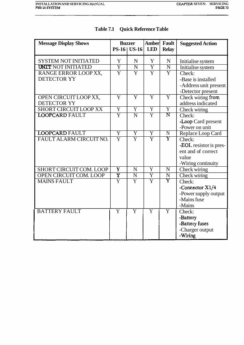
INSTALLATION AND SERVICING MANUAL CHAYIER SEVEN: SERVICING PBS16 SYSEM PAGE 72
Table 7.1 Quick Reference Table
Suggested Action
Initialise system Initialise system Check: -Base is installed -Address unit present -Detector present Check wiring from address indicated Check wiring Check: -Loop Card present -Power on unit Replace Loop Card Check: -EOL resistor is pres- ent and of correct value -Wiring continuity Check wiring Check wiring Check: -Connector X114 -Power supply output -Mains fuse -Mains Check:
Message Display Shows
SYSTEM NOT INITIATED UNIT NOT INITIATED RANGE ERROR LOOP XX, DETECTOR YY
OPEN CIRCUIT LOOP XX, DETECTOR YY SHORT CIRCUIT LOOP XX LOOPCARD FAULT
LOOPCARD FAULT FAULT ALARM CIRCUIT NO.
SHORT CIRCUIT COM. LOOP OPEN CIRCUIT COM. LOOP MAINS FAULT
BATTERY FAULT
-Charger output
PS-16
Y Y Y
Y
Y Y
Y Y
Y Y Y
Y
Amber LED
Y Y Y
Y
Y Y
Y Y
Y Y Y
Y
Buzzer US-16
N N Y
Y
Y N
Y Y
N N Y
Y
Fault Relay
N N Y
Y
Y N
N Y
N N Y
Y
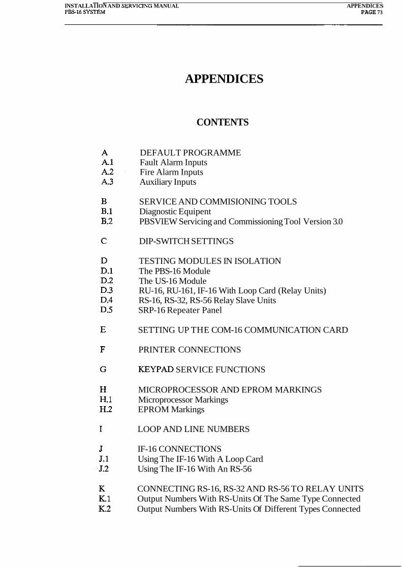
INSTALLATION AND SERVICISG MANUAL APPENDICES PBS-16 S Y m M PAGE 73
APPENDICES
CONTENTS
DEFAULT PROGRAMME Fault Alarm Inputs Fire Alarm Inputs Auxiliary Inputs
SERVICE AND COMMISIONING TOOLS Diagnostic Equipent PBSVIEW Servicing and Commissioning Tool Version 3.0
DIP-SWITCH SETTINGS
TESTING MODULES IN ISOLATION The PBS-16 Module The US-16 Module RU-16, RU-161, IF-16 With Loop Card (Relay Units) RS-16, RS-32, RS-56 Relay Slave Units SRP-16 Repeater Panel
SETTING UP THE COM-16 COMMUNICATION CARD
PRINTER CONNECTIONS
KEYPAD SERVICE FUNCTIONS
MICROPROCESSOR AND EPROM MARKINGS Microprocessor Markings EPROM Markings
LOOP AND LINE NUMBERS
IF-16 CONNECTIONS Using The IF-16 With A Loop Card Using The IF-16 With An RS-56
CONNECTING RS-16, RS-32 AND RS-56 TO RELAY UNITS Output Numbers With RS-Units Of The Same Type Connected Output Numbers With RS-Units Of Different Types Connected

INSTALLATION AND SERVICING MANUAL APPEhDICES P S 1 6 S Y m M PAGE 74
L CONFIGURING AND OPERATING THE SRP-16
TECHNICAL SPECIFICATIONS
CONDITIONS OF SALE
INDEX

INSTALLATION AND SERVICING MANUAL APPEKDIX A: THE DEFAULT PROGRAMME PS16 SYSTEM PAGE 75
APPENDIX A
THE DEFAULT PROGRAMME
The Default programme defines the effect of inputs on the outputs from the PBS-16 or US- 16 module. The programme is in permanent store on the Loop Card, and takes effect when no customised Cause and Effect EPROM is fitted to the card.
A1 Fault Alarm Inputs
The effects produced by fault alarm inputs at the PS-16 Information and Control Panel are unchanged by the presence or absence of the customised Cause and Effect programme.
There is a separate customised Text Message programme in an EPROM in the PS-16 Information and Control Panel. This determines the customised messages displayed. In its absence, the response to fault alarm inputs remains unchanged except for the absence of customised messages.
A.2 Fire Alarm Inputs
In the Default programme, apart from the displayed addresses, all alarm inputs produce the same effects.
These effects are:
(a) All four sounder outputs are operated.
(b) All three control relays are operated.
(c) Output signals on the internal communications bus operate all fire alarm outputs on all modules on the bus.
A3 Auxiliary Inputs
Auxiliary inputs 1 and 2 are disabled. Auxiliary input 3 (terminal block X4, terminals 27 ,
and 28) is enabled, and has the effect of putting the system into the Evacuate Mode when it is operated. During Evacuate Mode all the alarm bell circuits are activated.

INSTALLATION AND SERVICING MANUAL APPENDIX B: SERVICE AND COMMISSIONING TOOLS PBS-16 S Y S l E i PAGE 76
APPENDIX B
SERVICE AND COMMISSIONING TOOLS ' '
B.l Diagnostic equipment
Personal computer: With specially developed software (PBSVIEW) it is possible to interrogate, analyse and simulate alarms on a PBS-16 system.
Required: Portable PC (IBM compatible) 640k RAM 1 floppy disk drive 1 centronics interface 1 RS-232C serial port
For hard copies: 80 column printer with RS-232C serial port Centronics interface
For colour graphics: IBM PC or compatible 640k RAM 1 floppy disk drive 1 serial port RS-232C 1 Centronics interface 1 CGA graphics adaptor 1 colour monitor
B.2 PBSVIEW Servicing And Commissioning Tool Version 3.0
(The following is a copy of the README file on the PBSVIEW distribution disk).
SYSTEM SETUP
This diskette contains all necessary software for testing and commissioning PBS-16 systems. The software can be used on IBM PCs, ATs or compatibles with MS-DOS 2.1 or later version.
Files on this disk:
PBSVIEW. BAT --- Startup batch file VIEW.EXE --- Main program core LCOM.EXE --- Communication handler
This software is hardware-lock protected, that is, the enclosed hardware lock marked
i SIGNALCO SOFTWARE LOCK TYPE W03 must be installed on the computer serial port ,- COMl for this software to run.
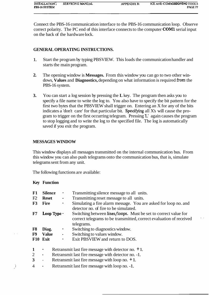
LUSTALLATION AND SERVICIKG MkVUAL APPELDIX B: SERVICE kW COMM1SSIOhIXG TOOLS PS16 SYSTEM PAGE 77
Connect the PBS-16 communication interface to the PBS-16 communication loop. Observe correct polarity. The PC end of this interface connects to the computer COMl serial input on the back of the hardware lock.
GENERAL OPERATING INSTRUCTIONS.
1. Start the program by typing PBSVIEW. This loads the communication handler and starts the main program.
2. The opening window is Messages. From this window you can go to two other win- dows, Values and Diagnostics, depending on what information is required from the PBS-16 system.
3. You can start a log session by pressing the L key. The program then asks you to specify a file name to write the log to. You also have to specify the bit pattern for the first two bytes that the PBSVIEW shall trigger on. Entering an X for any of the bits indicates a 'don't care' for that particular bit. Specifying all X's will cause the pro- gram to trigger on the first occurring telegram. Pressing 'L' again causes the program to stop logging and to write the log to the specified file. The log is automatically saved if you exit the program.
MESSAGES WINDOW
This window displays all messages transmitted on the internal communication bus. From this window you can also push telegrams onto the communication bus, that is, simulate telegrams sent from any unit.
The following functions are available:
Key Function
F1 Silence - Transmitting silence message to all units. F2 Reset - Transmitting reset message to all units. F3 Fire - Simulating a fire alarm message. You are asked for loop no. and
detector no. of fire to be simulated. F7 Loop Q p e - Switching between lines/loops. Must be set to correct value for
correct telegrams to be transmitted, correct evaluation of received . .
telegrams. F8 Diag. - Switching to diagnostics window.
.. . F9 Value - Switching to values window. F10 Exit - Exit PBSVIEW and return to DOS.
1 - Retransmit last fire message with detector no. + 1. 2 - Retransmit last fire message with detector no. -1. 3 - Retransmit last fire message with loop no. + 1.
,) 4 - Retransmit last fire message with loop no. -1.

INSTALLATION AND SERVICING ih4AihXAL p APPENDIX B: SERVICE AND COIMIMISSIONIXG TOOLS P m 1 6 SYSTEIM PAGE 78
B,b - C,c - D,d - L,l - M,m - N,n - 0 ,o - P,P -
- S,s - + - Space-
Set communication baud rate (5 = 2400 baud, 7 = 9600 baud). Change colour display. For use on some B/W screens. .
Dial phone number (Modem function). Start/stop log. Send message to modem (Modem function). Set communication port no. (1 = COM1,2 = COM2). Turns checksum-checking on incoming telegrams on/off. Dump-print screen to printer connected to LPT1. Retransmit last message. Create and transmit your own message. Hang up phone (Modem function). Alternative menu.
Keys that can be used while logging:
A,a - Autolog on/off. When autolog is on the log-window is automatically updated when a telegram is sent or received. The log-window will automatically be activated if not already active.
V,v - View on/off. Displays the contents of the current log buffer in the log-window. Switches the log window on/off. If autolog is on when pressing V then autolog is terminated and the log-window is turned off.
9 9 - (Full stop). Filter on/off. The filter is on, all Loop Card check telegrams, Loop Card reply telegrams and front card acknowledge telegrams are not logged. These will be logged if filter is turned off by pressing full stop.
Keys that can only be used while log is being displayed:
Home - Causes the Log-window to display the first log entries in the current log buffer.
End - Causes the Log-window to display the last log entries in the current log buffer.
Page Up - Displays the preceding page of the log buffer. Page Down - Displays the following page of the log buffer. Left Arrow - Places the first entry in the current log buffer, that occurred after the
log triggered, in the middle of the log-window. Up Arrow - Scrolls the log-window one line up. Down Arrow - Scrolls the log-window one line down.
VALUES WINDOW
From this window information internal to the Loop Card microprocessor can be acquired. The values presented on this screen are the same values as used by the microprocessor for checking fire and fault levels from any detector.
The following functions are available:
,) F1 Det Vals - Requesting loop no. and presenting the values read from each detec-

INSTALLATION AND SERVICING ,MANUAL APPENDIX B: SERVICE AND COMMISSIONING TOOLS P S 1 6 PAGE 79
tor connected to this loop. The top line of the screen will indicate loop number. The second line indicates static current supplied to . this loop. (Will indicate abnormal power consumption due to short circuit or power consuming units connected to the loop).
F2 Type Vals - Presenting values read when type checking during initiation. F3 Adj. values- Current adjustment values for analogue detectors. F7 Update Mode- Switching between manual and automatic updating of values on
screen. When in automatic updating mode, any detector with un- stable reading or faulty addressing unit is easily recognized.
F8 Diag. - Switching to diagnostics window. F9 Messages - Switching to messages window. F10 Exit - Exiting PBSVIEW and return to DOS.
H,h - Read values on same loop but from high end of loop. Loop type must be set to Loops.
L - Start/stop log. P,p - Dump-print screen to printer connected to LPT1. r - Request update. For updating values while in manual mode. Space- Alternative menu.
Keys that can only be used while logging:
. - (Full stop). Filter on/off. The filter equals the specified trigger pattern. While filter is on, all Loop Card check telegrams, Loop Card reply telegrams and front card acknowledge telegrams are not logged. These will be logged if filter is turned off by pressing full stop.
DIAGNOSTICS WINDOW
This window has been implemented to enable an automatic scan of all units and detector values. The routines used are the same as from the VALUES window. The computer collects all data and compares these with a set of recommended values and gives a rough estimate of the findings. This is of value as a quick indication of the state of a system, while for more elaborate analysis the VALUES window is recommended.
The following functions are available:
F1 Check All - Start checking of all units and unit addresses in order to give a :
total system overview. F2 Check Unit - Start checking of a specific unit address. F3 Loop Currents - Shows the loop currents for all units connected on com. loop. -.. . F7 Detail - Set detail of checking. F9 Values - Switching to values window. F10 Exit - Exit PBSVIEW and return to DOS
L,1 - Start/stop log. \
,) P,p - Dump-print screen to printer connected to LPT1.

INSTALLATION AND SERVICING MANUAL APPENDIX B: SERVICE AND COMMISSIONING TOOLS P m 1 6 SYSIEU PAGE 80
Keys that can only be used while logging:
. - (Full Stop). Filter on/off. The filter equals the specified trigger pattern. While filter is on, all Loop Card check telegrams, Loop Card reply telegrams and front card acknowledge telegrams are not logged. These will be logged if filter is . .
turned off by pressing full stop.
The different diagnostics levels are:
Brief - Giving a one-line information on all connected units in a system. Standard - A screen of short form information on each unit is presented. The infor-
mation is more detailed than a Brief mode, and an analysis of possible problems are given. The program pauses between each unit checked. To continue enter F1.
Extended - Same as standard with information on low/high detector addresses on each loop/line included.
When contacting A/S Signalco for help during commissioning and servicing, a printout of the PBSVIEW-screen is very helpful to us when recommending actions to be taken.
THE LOG FUNCTION AND THE LOGFILE
Logging the messages that are sent on the PBS-16 system's internal communication loop .
can be a valuable tool when trying to find spurious messages and their cause. The logfile will record when the message was sent, and it will also show the bytes transmitted. A short description of the telegram is also included.
The standard telegram is a five byte telegram built up as follows:
Byte 1 : Address of the receiving and transmitting units. Byte 2 : Function code. Byte 3, Byte 4 : Data. Byte 5 : Checksum.
Another type of telegram is the string telegram. The string telegram does not have a fixed length and takes the following form:
Byte 1 : Address of the receiving and transmitting units. Byte 2 : Function code. Byte 3, Byte 4 : Data. Byte 5 : Number of bytes to follow. Bytes 6 to last byte but one : Data.
Last byte : Checksum.
When the log function is activated, a filename must be specified for the logfile. The file- 1 name may include drive specification and a path as well as the actual filename. The 2'

INSTALLATIONAND SERVICING MANUAL APPE~BIX B: SERVICE AND COMMISSIONING TOOLS P S 1 6 SYSIEM PAGE 81
logfile's extension is always LOG. The drive specification, path and filename must not exceed 24 characters.
Using a filter when logging:
The filter specified gives the program the condition for starting the log. The two bytes specified by the filter must match the first two bytes of the transmitted telegram for the program to trigger. If, for example, we wanted to start logging only after having received a fire message from address number two then the two bytes must be specified as follows:
Byte 1 : 0000 0010 - The first four bits specify the to address, and the last four bits the from address.
Byte 2 : 00001010 - This is the function code for fire expressed in binary. The code for fire is 10 decimal.
Any bit in the two bytes may be specified as don't care by entering an x instead of 0 or 1. If byte 1 above had been specified as 'XXXXXXXX' then the program would have triggered on any telegram where byte 2 was 10.
If no filter is specified, (byte 1 and byte 2 specified as XXXXXXXX), then the program will trigger on the first telegram it sees.
After the program has triggered it will log every telegram that occurs. But it will not log Loop Card check telegrams, Loop Card reply telegrams and front card acknowledge tele- grams if the filter is left on. It is recommended that a filter is used since the logfile would get extremely large if the log was left on for a long time. - Often we don't know what trigger to specify, but at the same time we don't want to log all the Loop Card check related telegrams. In this case the following procedure may be fol- lowed:
1. Specify a dummy filter. This could be anything.
2. As soon as the message Waiting for trigger is displayed, the filter is turned off by pressing '.' (full stop). Now wait for the program to trigger. It will trigger on the first telegram it sees. Normally this would be a Loop Card check telegram.
3. Turn the filter back on to prevent the program from logging any subsequent Loop Card check related telegrams. The program will continue to log even though a telegram matching the specified trigger never was found.
Things to remember:
All parts of the PBSVIEW program may be used while logging, however, one must remem- ber that all messages sent from PBSVIEW are logged. This means that one for example would get a huge file filled with PBSVIEW requests and Loop Card answers if the auto mode is on while detector values are being checked.
\ . /'

INSTALLATION AND SERVICING MANUAL APPENDIX B: SERVICE AND COMMISSlONING TOOLS PS16 SYSEM PAGE 82
Known bug in PBSVIEW version 3.0:
If telegrams are constantly being sent on the communication loop the PBSVIEW program may 'crash' if one attempts to select the log function. The reason for this seems to be that the input communication buffer overflows while the program halts to read log parameters .-
such as logfile name and trigger bytes. This situation should not arise under normal circumstances, but only happens if a new telegram is constantly being sent only millisec- onds after the previous sending has ended.
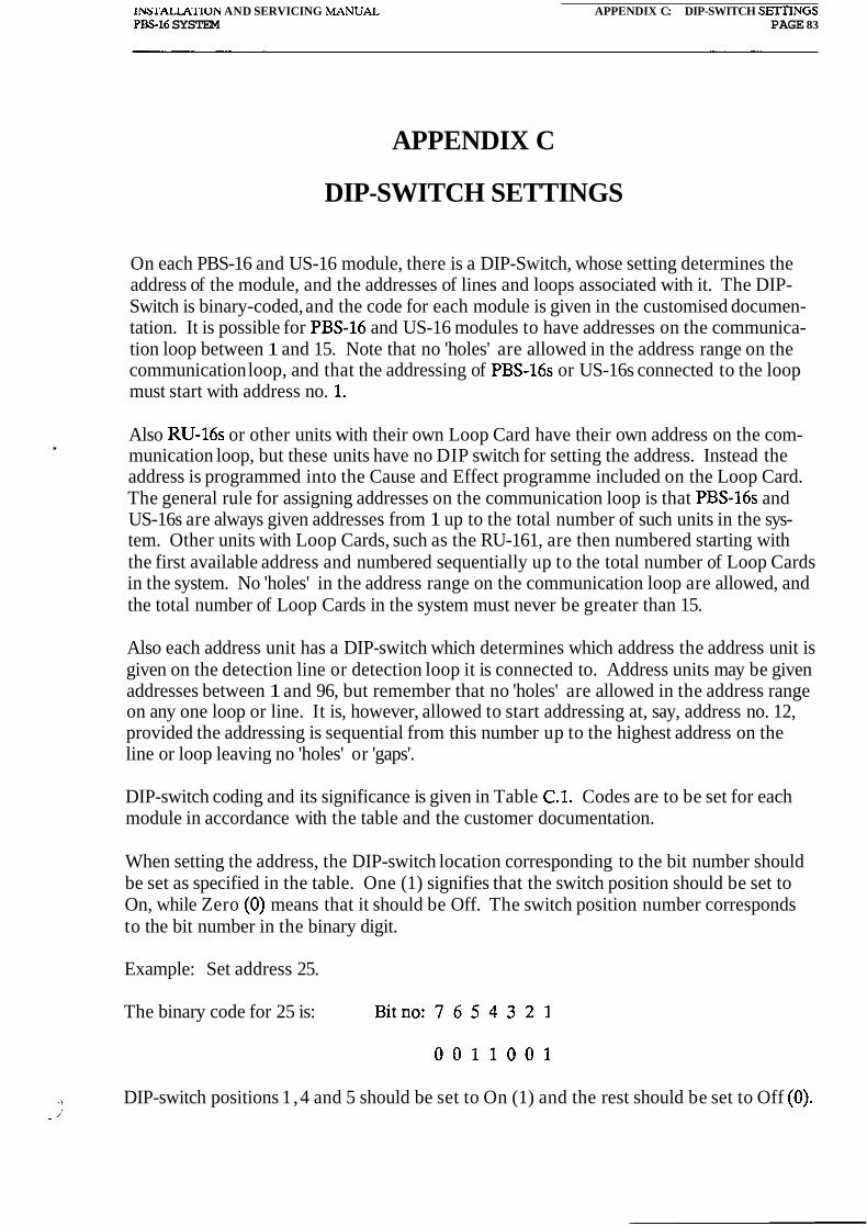
INSl.ALMIION AND SERVICING MANUAL APPENDIX C: DIP-SWITCH SElTINGS P S 1 6 SYSTEM PAGE 83
APPENDIX C
DIP-SWITCH SETTINGS
On each PBS-16 and US-16 module, there is a DIP-Switch, whose setting determines the address of the module, and the addresses of lines and loops associated with it. The DIP- Switch is binary-coded, and the code for each module is given in the customised documen- tation. It is possible for PBS-16 and US-16 modules to have addresses on the communica- tion loop between 1 and 15. Note that no 'holes' are allowed in the address range on the communication loop, and that the addressing of PBS-16s or US-16s connected to the loop must start with address no. 1.
. , Also RU-16s or other units with their own Loop Card have their own address on the com- munication loop, but these units have no DIP switch for setting the address. Instead the address is programmed into the Cause and Effect programme included on the Loop Card. The general rule for assigning addresses on the communication loop is that PBS-16s and US-16s are always given addresses from 1 up to the total number of such units in the sys- tem. Other units with Loop Cards, such as the RU-161, are then numbered starting with the first available address and numbered sequentially up to the total number of Loop Cards in the system. No 'holes' in the address range on the communication loop are allowed, and the total number of Loop Cards in the system must never be greater than 15.
Also each address unit has a DIP-switch which determines which address the address unit is given on the detection line or detection loop it is connected to. Address units may be given addresses between 1 and 96, but remember that no 'holes' are allowed in the address range on any one loop or line. It is, however, allowed to start addressing at, say, address no. 12, provided the addressing is sequential from this number up to the highest address on the line or loop leaving no 'holes' or 'gaps'.
DIP-switch coding and its significance is given in Table C.1. Codes are to be set for each module in accordance with the table and the customer documentation.
When setting the address, the DIP-switch location corresponding to the bit number should be set as specified in the table. One (1) signifies that the switch position should be set to On, while Zero (0) means that it should be Off. The switch position number corresponds to the bit number in the binary digit.
Example: Set address 25.
The binary code for 25 is:
> DIP-switch positions 1 ,4 and 5 should be set to On (1) and the rest should be set to Off (0). -l'

INSTALLATION AND SERVICING MANUAL APPENDIX C: DIPSWITCH SEITINGS P m 1 6 SYSTEiM PAGE 84
Table C.l
DIP Switch Coding
A = Address
A Bits 7 6 5 4 3 2 1
A Bits 7 6 5 4 3 2 1
A Bits 7 6 5 4 3 2 1
NOTE: A zero (0) specifies a DIP-switch position set to OFF, and a one (1) specifies that the corresponding DIP-switch position should be set to ON.
\ .A

INSTALLATION AND SERVICIXG ILWIYUAL Pm16 SY-
APPENDIX D: TESIIXG MODULES IN ISOLATION PAGE 85
APPENDIX D
TESTING MODULES IN ISOLATION
The only module that can be fully checked in isolation is the PBS-16 module. The reason for this is that it is only this module that have a man/machine interface (PS-16 Control and Information Panel). The PBSVIEW test and commissioning tool may only be used if the internal Communication Bus is operational. This Comms Bus is a current loop, and the current originates from the PS-16 panel. It is therefore not possible to connect PBSVIEW to a module that is not in some way linked to a PS-16 Control and Information panel.
Testing in isolation of other modules is therefore mostly a series of visual checks.
D.1 The PBS-16 Module
The PBS-16 module can be fully tested in isolation. The US-16 motherboard the PS-16 is connected to will normally have its DIP-switch set to address 1. This may not be the case if there is more than one PBS-16 module in the system, or if a different numbering conven- tion have been used. To proceed with the test the US-16 motherboard DIP-switch marked S1 must be set to address 1. How to do this is explained in Appendix C.
The module is now tested as explained in chapter 6, sections 6.1 up to 6.9.2 inclusive. A complete test of the module have now been carried out. If the modules address on the Comms Bus is different to 1 must the S1 DIP-switch be correctly set before the module is connected to the rest of the system.
Note that the ST2 and ST3 bridging links, (see fig. 6.2), on the US-16 motherboard should only be cut if the module is the main PBS-16 module in the system. If there is only one PBS-16 module should the links be cut on that unit.
D.2 The US-16 Module
Also the US-16 module may be fully tested in isolation if a PS-16 Control and Information panel is temporarily connected to it. The module then,effectively becomes a PBS-16 mod- , .. ule and testing is as explained for that module. Note that the bridging links ST2 and ST3 never should be cut on a US-16 module.
If a PS-16 panel is not available is only a series of visual inspections possible before con- nection to the Internal Communication Bus.
a. Check that all wiring for the charger and battery connection is correct. If the module is not used to monitor the battery or charger should this monitoring have been dis- abled. This is done by removing two PTC resistors and connecting a short circuit between X1/4 (Mains Con.) and X2/1 (Battery +). The two PTC resistors are

WALLATION AYD ~ERVICIXG MANUAL APPEXDIX D: TESTING ,MODULES IN ISOLATION P S 1 6 SY!XEIM PAGE 86
marked R52 and R71 and are located directly below the relays on the US-16 mother- board.
Check that the Loop Card is present and is correctly plugged into the P3 edge con- nector. The card must be pushed all the way down unto the connector. Also check that the Loop Card has the correct type of software plugged in. See Appendix H for microprocessor markings and Operator's Manual Part 2 for Cause and Effect EPROM markings.
Check that the S1 switch is set to the correct address. See Appendix C.
Check all detector lines or loops for short circuits and open circuits. Make sure all wires are correctly terminated.
Check the alarm bell circuits for short circuits and open circuits. Check that the EOL resistor (10 kohm) is correctly connected and of the correct value. Check that the sounder devices are polarised and connected the correct way around.
Check all circuits connected to the Control Relays and the Fault Relay.
Check that the circuitry connected to the Voltage Failure terminals operate.
Check that the Auxiliary Inputs are correctly connected.
Check that the equipment powered from the three 24V DC outputs are not short circuit.
If an RS-unit is connected check that it is correctly connected. See figures 5.3'5.4 and 5.5. Also check that all circuits connected to this unit is correctly wired and have no short circuits.
Check all fuses.
1. All faults revealed during the checks specified in points (a) to (k) must be put right. The module should now be connected to the Communication Bus. The module is powered up as explained in sections 6.3 and 6.4 and commissioning continues as explained in section 6.10.3.
D.3 RU-16, RU-161, IF-16 With Loop Card (Relay Units)
These modules may only be visually inspected before they are connected to the Communi- cation Bus and powered up.
a. Check that the 24V DC connections are correct.
b. Check all fuses.
1 c. Check the wiring of all connected circuits. This is particular important for the IF-16 1'

lNSTALLATION AND SERVICING M W A L APPENDIX D: TESTING MODULES IN ISOLATIOK PS16 SYSIEM PACE 87
with loop card since no protection is provided for its inputs or outputs.
d. Check that all wires are terminated correctly at the correct terminal. e. Check that RS-units are correctly connected and that all circuits connected to them
have no short circuits or other wiring faults.
f. Check that the Loop Card is pushed all the way onto the edge connector. Check that the Loop Card is fitted with the correct microprocessor and Cause and Effect EPROM. An EPROM must always be included on the Loop Card controlling Relay Units. Microprocessor markings are explained in Appendix H, while C&E EPROM markings are explained in Operator's Manual Part 2.
g. Correct all faults found during points (a) to (f). Connect the module to the Commu- nication Bus and carry on the commissioning procedure as explained in section 6.10.4.
D.4 RS-16, RS-32, RS-56 Relay Slave Units
These units are inspected during the inspection of the modules they are connected to. See D.2 and D.3.
D.5 SRP-16 Repeater Panel
A visual check should include the following points:
a. Check that it is correctly configured. Appendix L explains how to do this. Operator's Manual Part 2 should give details of how the SRP-16 should be configured.
b. Check Operator's Manual Part 2 to find out if a Text EPROM should be fitted at the back of the SRP-16's PCB. Check that EPROM is fitted correctly and that the mark- ing matches the marking specified in Operator's Manual Part 2.
c. Check that the 24V DC supply is correctly connected.
d. Connect the Communication Bus and check that the correct messages are displayed when faults or fires are simulated.
e. Check that- the module operates as configured. Check Silence and Reset. Check Operator's Manual Part 2 to find out if any Cause and Effect for the SRP-16's relays is included, and test this for correct response if it is.

INSTAUTION AND SERVICING MANUAL APPENDIX E: SEITING UP THE COM-16 COMMUNICATION CARD P S 1 6 SYSIEU PAGE 88
APPENDIX E
SETTING UP THE COM-16 COMMUNICATION CARD
The COM-16 Communication Card may only be used in a US-16 that has a PS-16 front connected. The combination of a PS-16 and a US-16 is usually referred to as a PBS-16.
The Communication Card is controlled by the PS-16 card through the 40-way ribbon cable used to connect the PS-16 to the US-16 motherboard. The COM-16 card is placed in the slot provided on the motherboard.
CAUTION!
IT IS ESSENTIAL THAT POWER IS COMPLETELY REMOVED BEFORE INSERTING THE COMMUNICATION CARD OR
BEFORE REMOVING IT. FAILURE TO DO THIS USUALLY LEADS TO DAMAGE OF THE COiM-16 CARD.
The Communication Card has two communication ports. Port 1 is a RS-232C port and is usually used for printer connection. Port 1 is the connector marked P3, and it is the left- most connector. The DIP switch marked S1 is used to select the communication speed (ie. the Baud rate) for this port. This switch is located to the far right on the card. Baud rates available are 300,600,1200,2400,4800 and 9600. Normally the 9600 baud rate is used when a printer is connected. Note that only one of the switches in S1 may be set to ON at the same time. A good way to remember which switch belongs to which port is to remem- ber that the rightmost switch belongs to the leftmost port.
Port 2 is normally used for communication with other PBS-16 systems or a computer. Port 2 is the connector marked P2. Three different configurations may be selected for this port. This is done with DIP switch S3. Only one of the switches in S3 may be set to On at any one time. The marking on the card indicates how to select between the following configu- rations:
RS-232C 20mA current loop RS485
NOTE that RS-232C is also the normal configuration for Port 2, and that the PS-16 soft- ware determines which configurations may be used in your system See Operator's Manual Part 2.
i The Baud rate for Port 2 is selected by using DIP switch S2. The normal speed for commu-
.J nication with a computer using the PBSVIEW diagnostic software is 2400. Note that only one of the switches in S2 may be set to ON at any one time.

INSTALLATION AND SERVICING MANUAL APPENDIX F: PRJNlER CONNECTIONS PS16 SYSIEM PACE 89
APPENDIX F
PRINTER CONNECTIONS
For a printer to be used with the system, there must be a COM-16 Card fitted in socket P2 on the Loop Card on the master PBS-16 module.
CAUTION!
POWER SUPPLIES (INCLUDING THE BATTERY SUPPLY) MUST BE DISCONNECTED BEFORE A COM-16 CARD IS EITHER
PLUGGED IN OR REMOVED.
Standard printers, such as the Epson LX800 may be used.
The following parameters must be set at the printer:
Speed 9600 baud Parity none Databits 8 Stopbits 1 Language local
The printer connecting cable should be as follows:
(a) For a 25 pin plug at the printer:
PBS-16 (25 pin)
Printer (25 pin)
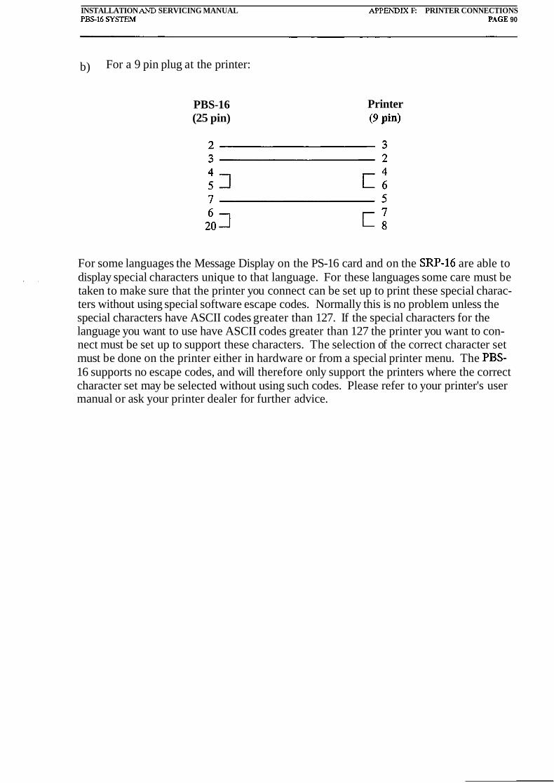
INSTALLATION AiiD SERVICING MANUAL APPESDIX F: PRINTER CONNECTIONS P m 1 6 SYSIEM P.4GE 90
b) For a 9 pin plug at the printer:
PBS-16 (25 pin)
Printer (9 pin)
For some languages the Message Display on the PS-16 card and on the SRP-16 are able to . . display special characters unique to that language. For these languages some care must be
taken to make sure that the printer you connect can be set up to print these special charac- ters without using special software escape codes. Normally this is no problem unless the special characters have ASCII codes greater than 127. If the special characters for the language you want to use have ASCII codes greater than 127 the printer you want to con- nect must be set up to support these characters. The selection of the correct character set must be done on the printer either in hardware or from a special printer menu. The PBS- 16 supports no escape codes, and will therefore only support the printers where the correct character set may be selected without using such codes. Please refer to your printer's user manual or ask your printer dealer for further advice.

INSTALLATION AND SERVICING MANUAL APPENDIX G: KEYPAD SERVICE FUNCTIONS PBS16 S Y S E M PAGE 91
APPENDIX G
KEYPAD SERVICE FUNCTIONS
The Operating Manual lists and describes the use of many of the functions available by use of the keypad. These include functions 1 to 15, 17 and 18.
The remaining functions are listed and described here.
MAINTENANCE AND ANALYSIS FUNCTIONS
These functions are primarily for the use of service personnel, and some of them may not be available on all panels.
The functions written in bold are only available when a printer or computer is connected to the system.
Function 16 Search Faults
List Loop Value (%) List Sensor Value (%) Print Sensor Types Print Sensor Values (%) Print Sensor Values Between Limits List Address Range Per Loop Connect modem Version number. Gives core software version number. Central 0 = PS-16
30 Initiate all uninitiated parts of the system. 3 1 List Initialise Parameters 32 Initialise Specified Unit 33 Set Lines/Loops 34 De-initialisation
INSTALLATIO~VAND SERVICING WVUAL APPENDIX H: MICROPROCESSOR AND EPROM MARKINGS PBS-16 SYSIEM PACE 92
APPENDIX H
MICROPROCESSOR AND EPROM MARKINGS
H.l Microprocessor Markings
A typical marking of a microprocessor for the Loop Card is:
PBS16SA AD Ver. 3.0
The first line refers to what type of card the processor belongs to. PBS16SA is the official name of the Loop Card. This line does not specify where this Loop Card is used.
The second line specifies exactly what type of software has been burnt into the processor's internal EPROM. This line consists of a few letters indicating the program type and a . . . version identifier.
The letters starting the second line may be:
AD Analogue sensors in a loop configuration. AE Analogue sensors in a line configuration.
DD Digital (or conventional addressed) detectors in a loop configuration. DE Digital (or conventional addressed) detectors in a line configuration.
KD Conventional detectors in a loop configuration. KE Conventional detectors in a line configuration.
RU16 Processor intended to be used on a Loop Card placed in a RU-16. Later ver- sions of this software (Version 3.0 or later) are also compatible with the RU-161. This chip may also be used on a Loop Card on the IF-16 interface card to make a mimic driver.
RU16I Identical to same version of the RU16 software. Very few chips with this mark- ing have been made, and in the future, probably only the RU16 marking will be used, since they are identical.
The version number indicated on the marking label is the same as the version number one gets by using function 26 from the PS-16 Control Panel.

INSTALLATION AND SERVICING MANUAL APPENDIX H: MICROPROCESSOR AND EPROM MARKINGS P S 1 6 SY- PAGE 93
H 2 EPROM Markings
This section only applies to EPROMs contained in the core software for the PS-16 Control Panel (that is, the PBS-16 front card).
A typical marking is:
PBS16FA ADEN Ver. 3.11
As for the Loop Card processors, the first line only indicates what type of card the EPROM is made to work with. PBS16FA is equivalent to the PS-16 card, or the PBS-16 front card as it is sometimes known.
The second line consists of four letter indicating loop or line type, line or loop configura- tion, and language used for the text display. The rest of the line is for version number identification.
The two first letters have the same meaning as the letters on the second line of the marking of the Loop Card processors. (Only those intended to be used with a Loop Card placed in a US-16 module). The last two letters indicate the language.
For the first letter:
A Means analogue type of sensors in the system D Means digital (or conventional addressed) type of detectors in the system.
The second letter:
E Means line configuration. D Means loop configuration.
The last two letters:
Dutch text (for Belgium) Danish text English text French text Italian text Icelandic text Norwegian text Spanish text Swedish text
The version number indicated on the marking label is the same as the version number one gets by using function 26 from the PS-16 Control Panel. A PS-16 panel always has address 0 (zero), even if there is more than one control panel in the system.
1
INSTALIATION AND SERVICIXG LMANUAL APPENDIX I: LOOP AND LINE NUMBERS P S 1 6 SY!nEM PAGE 9.1
APPENDIX I
LOOP AND LINE NUMBERS
The quiescent current on a loop may be read by using function 19 on the front panel. When there is more than one module in the system, the loops or lines are numbered ac- cording to the address on the communication bus given to the unit they are connected to. Table L1 shows which loop or line numbers corresponds to the different addresses on the communication bus.
Function 19 may also be used to read the value on one of the RU-161 analogue inputs. But when this is done the following points must be remembered:
1. In a line system the RU-161 analogue input gets the same number as the correspond- ing line would have had if the RU-161 had been a US-16. So if the RU-161 has ad- dress 5 on the communication bus inputs 1 to 16 are referred to as lines 65 to 80 when using function 19.
2. In a loop system function 19 cannot be used in the same way. The reason for this is that function 19 only returns the value read on the low end of a loop. This means that only the first eight of the RU-16I's inputs can be checked from the keyboard. The other eight inputs (analogue inputs 9-16) can be checked by using PBSVIEW. The easiest way to do this is to press F3 while in Diagnostic Mode. This automatically puts up all loop currents read from both ends of the loop for every module connected.
The loop or line number may also be calculated by considering the module address, system configuration, and the detection input number the line or loop is connected to. The equa- tions below show how this is done:
For a loop configuration:
Loop Number = ((US-16 address - l ) X 8) + Detection input number
Note that it is the lower detection input number that is used for each loop. For example the low end of loop one is connected to detection input no 1, while the high end of the same loop is connected to detection input no 9. The detection input number 1 is used to calculate the loop number.
For a line configuration:
Line number = ((US-16 address - l ) X 16) + Detection input number
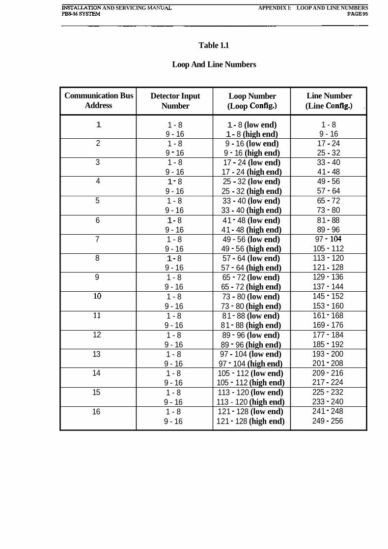
INSTALIATION AND SERVICING MANUAL APPENDIX I: LOOP AND LINE NUMBERS PS16 SY- PAGE 95
Table 1.1
Loop And Line Numbers
Line Number (Line Config.) .
1 - 8 9 - 16 17 - 24 25 - 32 33 - 40 41 - 48 49 - 56 57 - 64 65 - 72 73 - 80 81 - 88 89 - 96 97 - 104 105 - 112 113 - 120 121 - 128 129 - 136 137 - 144 145 - 152 153 - 160 161 - 168 169 - 176 177 - 184 185 - 192 193 - 200 201 - 208 209 - 216 217 - 224 225 - 232 233 - 240 241 - 248 249 - 256
Communication Bus Address
1
2
3
4
5
6
7
8
9
10
11
12
13
14
15
16
Detector Input Number
1 - 8 9 - 16 1 - 8 9 - 16 1 - 8
9 - 16 1 - 8 9 - 16 1 - 8 9 - 16 1 - 8 9 - 16 1 - 8 9 - 16 1 - 8 9 - 16 1 - 8 9 - 16 1 - 8 9 - 16 1 - 8 9 - 16 1 - 8 9 - 16 1 - 8 9 - 16 1 - 8 9 - 16 1 - 8 9 - 16 1 - 8 9 - 16
Loop Number (Loop Config.)
1 - 8 (low end) 1 - 8 (high end) 9 - 16 (low end) 9 - 16 (high end) 17 - 24 (low end) 17 - 24 (high end) 25 - 32 (low end) 25 - 32 (high end) 33 - 40 (low end) 33 - 40 (high end) 41 - 48 (low end) 41 - 48 (high end) 49 - 56 (low end) 49 - 56 (high end) 57 - 64 (low end) 57 - 64 (high end) 65 - 72 (low end) 65 - 72 (high end) 73 - 80 (low end) 73 - 80 (high end) 81 - 88 (low end) 81 - 88 (high end) 89 - 96 (low end) 89 - 96 (high end) 97 - 104 (low end) 97 - 104 (high end) 105 - 112 (low end) 105 - 112 (high end) 113 - 120 (low end) 113 - 120 (high end) 121 - 128 (low end) 121 - 128 (high end)

IXSTALLATION AXD SERVICISG ,MXSL:AL APPEXDIX J: IF-16 COXNECIIONS PBS-16 S Y m N PACE 96
APPENDIX J
IF-l6 CONNECTIONS
The IF-16 Interface Card has a edge connector which is used for either plugging in a Loop Card or a RS-56 Output Driver Card. Two rows of connection terminal blocks enable wires to be connected to the plugged-in card's various input and output lines. The card has a 5V regulator which is enabled when the straps located directly above connection terminal block X1 is fitted.
It is absolutely essential that one look directly down on the card when a wire is connected to the card. It is very easy to connect a wire to the neighbouring terminal if one is at an angle to the card while the wire is being inserted into the terminal block.
J.l Using The IF-16 With A Loop Card
The IF-16 on-board 5V regulator must be enabled. This is done by fitting the straps lo- cated directly above connection terminal block XI.
When the Loop Card is used together with the IF-16 a wide range of the Loop Cards input and output possibilities are available.
The following outputs are available:
16 Switchable 24VDC outputs. 4 Sets of connection terminals for RS-Units. 1 External buzzer output.
The following inputs are available:
16 Analogue inputs. 3 Digital inputs.
The Loop Card must carry the same Core Software as the Loop Cards used in a RU-16 or a RU-161. The 16 analogue inputs, the 16 24VDC outputs and the connection terminals for RS-Units are, apart from lack of protection and missing relays, identical to the correspond- ing inputs and outputs on the RU-161. The three digital inputs are, apart from missing protection, the same as the auxiliary inputs on the US-16. In Cause and Effect the inputs and outputs provided are used in exactly the same way as the corresponding inputs and outputs on the RU-161 and the US-16.

INSTALLATION A h D SERVICING MANUAL APPEVDIX J: IF-16 CONNECTIONS P S 1 6 SYSTEM PAGE 97
WARNING!
NO PROTECTION IS PROVIDED ON THE 5V INPUTS OR OUTPUTS. BURNOUT WILL
OCCUR IF MAXIMUM RATINGS ARE EXCEEDED.
The inputs and outputs have no protection against overloading, over-voltage or noise. If this is required must this be fitted externally or other modules must be used. It is abso- lutely essential that input and output currents are kept within the specified limits.
Note that the 24VDC input may be connected to terminals X112 and X113 or X212 and X2/3. The 24VDC connection terminals not used for 24VDC feed becomes a spare set of connection terminals for 24VDC output. So if the 24VDC feed is connected to the termi- nals in block X1 can the 24VDC feed to other equipment be taken from the terminals in block X . .
Figure J.l shows the function of each of the connections terminals on the IF-16 when used with a Loop Card.
Outputs 1 to 16 can drive relays or LEDs, but the maximum current drive per output is 100 mA.
Inputs 1 to 16 can take voltage between OV and 5V. The input impedance is 100 ohms. A series resistor should be fitted to limit the possible input current to maximum 50 mA.
The clock and data outputs are common for all RS-Units connected, but a separate enable line is provided for each RS-Unit. The RS-Enable line used determines the output num- bers associated with the various RS-Units.
5.2 Using The IF-16 With An RS-56
The IF-16 on-board 5V regulator must be disabled. It is disabled if the straps located directly above terminal connection block X1 are cut or not fitted at all.
The RS-56 used together with the IF-16 provides 56 24VDC switchable outputs. These outputs are suitable for driving LEDs or relays. The RS-56 is controlled by the Loop Card it is connected to, and the Cause and Effect fitted on that card determines which outputs are operated upon certain events in the system.
Note that the maximum current.allowed drawn from a single output is 100 mA. The maxi- mum total load (all 56 outputs) allowed is 2A.
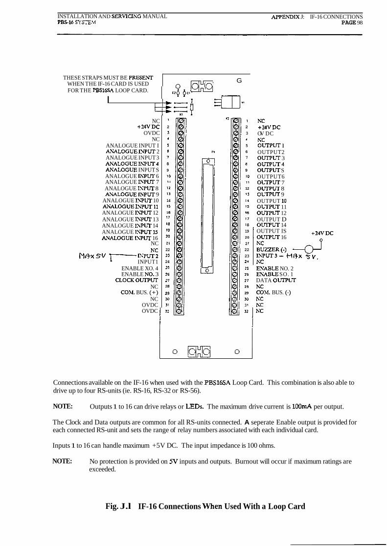
INSTALLATION AND SERVICIXG MANUAL APPEhDIX J: IF-16 CONNECTIONS P S 1 6 SYSIEN PAGE 98
THESE STRAPS MUST BE PRESEiLT WHEN THE IF-16 CARD IS USED
+ U V D C OV DC KC OLTPUT l OUTPUT2 OUTPLT 3 OUTPUT4 OLTPUT S OUTPUT6 O ~ r n U T 7 OUTPbT 8 ObTPUT 9 OUTPUT l0 ObTPbT 11 OIA-F'UT 12 OUTPUT D ObiTPUT 14
0 m G
FOR THE PBSldSA LOOP CARD.
I
NC +24VDC
OVDC NC
ANALOGUE INPUT I AYALOGUE I W U T 2 ANALOGUE INPUT 3 A i L O G U E II\;PUT4 AYALOGUE INPUT S ANALOGUE IXPUT 6 ANALOGUE ISPUT 7 ANALOGUE ISPUT 8 AXALOGUE IXPUT 9
ANALOGUE IXPUT 10 A U L O G U E IhTUT 11 ANALOGUE ISPUT 12 ANALOGUE ISPUT 13 ANALOGUE IXPUT 14 ANALOGUE ISPUT 15 AWALOGUE ISPUT 16
NC h'c
M f h s v I PUT2 INPUT1
ENABLE XO. 4 ENABLE NO. 3
CLOCKOliTPbT NC
COhl. BUS. (+) NC
OVDC OVDC
OUTPUT IS OLTPUT 16
c>+ 8.1
- ts=l X1
1 1
2 2
3 3
4 4
s 5
6 PI 6
7 7
8 8
9 9
10 10
i i 1 1
12 12
1 3 13
14 14
15 15
16 16
l7 17
'8 18
'9 19
20 20
21 2 1
22 22
23 23 24 24
25 25
26 26
27 27
28 23
29 29
M 30
31 3 1
32 32
ESABLE NO. 2 EXABLE SO. 1 DATA OUTPLT NC COh1. BUS. (-) KC NC
Connections available on the IF-16 when used with the PBS16SA Loop Card. This combination is also able to drive up to four RS-units (ie. RS-16, RS-32 or RS-56).
NOTE: Outputs 1 to 16 can drive relays or LEDs. The maximum drive current is lOOm.4 per output.
The Clock and Data outputs are common for all RS-units connected. A seperate Enable output is provided for each connected RS-unit and sets the range of relay numbers associated with each individual card.
Inputs 1 to 16 can handle maximum +5V DC. The input impedance is 100 ohms.
NOTE: No protection is provided on 5V inputs and outputs. Burnout will occur if maximum ratings are exceeded.
Fig. J.l IF-16 Connections When Used With a Loop Card

INSTALLATION AND SERVICISG MANUAL APPENDIX J: IF-16 CONNECTIONS P S 1 6 SYSE.34 PAGE 99
NO SITUPS MAY BE PRESEhT IN THESE POSITIONS WHEN THE IF-16
0
CARD IS USED WlTH THE RS56 CARD ,,Q Q c, a +BVDC 1
2
O L V U T I 3 3
OUTPUT3 4
OUTPUTS 5 5 o L w U T 7 6 PI 6
OUTPUT9 7 7
OUTPLT 11 a
OUTPUT13 9
O b V U T 15 '0 l0
OLTPUT 17 '1 1 1
OLTPUT 19 12 12
Ou'lTUT 21 l 3 13
Obm'UTU l 4 I4
OLTPW 25 l5 15
OLTPLT27 1" 16
O L T P U T ~ ~ 17 I:
OLTPUT31 18 18
OUTPUT33 l9 19
OLTPUT35 20 20
OLTPUT37 21 21
OUTPUT39 22 22
OUTPUT41 23 23
O L T P U T ~ ~ 24 24
OLTPUT45 25 2:
OUTPUT47 26 26
0 ~ ~ ~ 1 x 4 9 27 27
ObTPbTS1 28 28
OLTPUT53 29 29
OLTPUTSS 30 30 3 l
CLOCKINPUT 32 s2
OV DC OUTPUT 2 OUTPUT 4 OUTPUT 6 OLTPUT 8 OUTPUT l0 OUTPUT 12 OUTPUT 14 OUTPUT 16 OLTPUT l8 OUTPUT 20 OUTPUT22 OUTPUT 24 OUTPUT 26 OUTPUT 28 OUTPUT30 OUTPUT 32 OUTPLT 33 OUTPUT 36 OLTPUT 38 OUTPUT40 OUTPUT 42 OUTPUT 44 ObTPUT 46 OUTPUT48 OUTPLT 50 OUTPUT52 OLTPUT 54 OUTPUT56 ENABLE DATA IXPLT
Connections available on the IF-16 when used with the RS-56 output driver card.
NOTE: Outputs 1 to 56 can drive relays or LEDs. The maximum drive current is lOOrnA per output. The total current for all 56 outputs combined must not exceed 2A.
Fig. 5.2 IF-16 Connections When Used With The RS-56 Card
INSTALLATION AlVD SERVICING LMANUAL APPENDIX K: CONNECnlVG RS16, RS32 AND m 5 6 TO RELAY UNITS P m 1 6 SYSIEM PAGE 100
APPENDIX K
CONNECTING RS-16, RS-32 AND RS-56 TO RELAY UNITS
The following units may all have up to four RS-Units connected to them:
RU-16 RU- 161 Loop Card Placed On IF-16 Card. (See fig. J.1)
Through the rest of this appendix I will refer to all these units as Relay Units.
K.l Output Numbers With RS-Units Of The Same Type Connected
In Cause and Effect certain parameters are set to signal certain things to the microproces- sor. Parameter 11 (P[11]) is used to inform the microprocessor if the loop card is control- ling RS-16s or RS-56s. This parameter must always be set if the Relay Unit has a RS-32 or a RS-56 connected.
In the tables below the output numbers listed is the relay number used in Cause and Effect programming.
Table K.1 lists the outputs available when only RS-16s are connected to the Relay Unit.
Table K.2 lists the outputs available when only RS-32s are connected to the Relay Unit.
- Note that gaps are left in the output number range when RS-32s are connected. The rea- ' . son for this is that the Relay Unit does not know what type of relay units it has connected.
All it knows is that it is,not RS-16s that it has connected. It therefore assumes that each RS-Unit connected is a RS-56. This means that it will shift out 56 bits of data for every RS- Unit. The RS-32 only needs 32 bits of data and loses the 24 first bits shifted out. So output one on the RS-32 becomes what would have been output 25 if a RS-56 had been con- nected.
Table K.3 lists the outputs available when only RS-56s are connected to the Relay Unit.
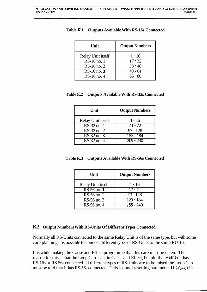
INSTALLATION AND SERVICING MANUAL APPENDIX K: CONNECTING RS-16, S 3 2 AhII S 5 6 TO RELAY UNITS PBS16 SY!iXEN PAGE 101
Table K.1 Outputs Available With RS-16s Connected
Table K.2 Outputs Available With RS-32s Connected
Unit
Relay Unit itself RS-16 no. 1 RS-16 no. 2 RS-16 no. 3 RS-16 no. 4
Output Numbers
1 - 16 17 - 32 33 - 48 49 - 64 65 - 80
Table K.3 Outputs Available Wit h RS-56s Connected
Unit
Relay Unit itself RS-32 no. 1 RS-32 no. 2 RS-32 no. 3 RS-32 no. 4
Output Numbers
1 - 16 41 - 72 97 - 128
153 - 184 209 - 240
K 2 Output Numbers With RS-Units Of Different Types Connected
Unit
Relay Unit itself RS-56 no. 1 RS-56 no. 2 RS-56 no. 3 RS-56 no. 4-
Normally all RS-Units connected to the same Relay Unit is of the same type, but with some care planning it is possible to connect different types of RS-Units to the same RU-16.
Output Numbers
1 - 16 17 - 72 73 - 128 129 - 184 185 - 240
It is while making the Cause and Effect programme that this care must be taken. The reason for this is that the Loop Card can, in Cause and Effect, be told that wether it has RS-16s or RS-56s connected. If different types of RS-Units are to be mixed the Loop Card must be told that it has RS-56s connected. This is done by setting parameter 11 (P[11]) in

INSTALLATION AND SERVICISG 5L4NUAL APPESDIX K COSNECTISG RS-16, S 3 2 ASD S 5 6 TO RELAY USlTS PBS-16 SYSTE.? PAGE 102
Cause and Effect.
The effect of connecting different types of RS-Units to the same Relay Unit is similar to what happens when only RS-32s are connected to it. This is explained in section K.1. What happens is that the output numbers available will vary depending on what type of RS- Units are connected and on which RS-Enable line it is connected to.
The Relay Unit assumes it has up to four RS-56s connected to it. The RS-56s outputs would, in Cause and Effect, be numbered from 17 to 240. The output numbers for each connected RS-Unit is shown in Table K.3.
An RS-56 connected will always occupy the output numbers specified in table K.3 for that particular RS-Unit. The last available output on the RS-Unit connected will always have the same output number as an RS-56 connected to the same RS-Enable line would have had. If the RS-Unit is connected to RS-Enable line no. 3 will the last output on that RS- Unit have the output number 184. (See Table K.3).
The output number for the first output on the RS-Unit is found by simply taking the nurn- ber already found, add one, and then subtract the number of outputs on the RS-Unit con- nected. If the first number we found was 184 and we have connected an RS-16 to RS- Enable line no. 3 then the first output number is:
Table K.4 shows the output numbers we would have got if we had had the following RS- Units connected to a Relay Unit:
RS-Enable Line no. 1 - RS-32 RS-Enable Line no. 2 - RS-16 RS-Enable Line no. 3 - RS-16 RS-Enable Line no. 4 - RS-56
Table K.4 Output Numbers Available With Different Types Of RS-Units Connected.
Unit
Relay Unit itself RS-32 (Enable 1) RS-16 (Enable 2) RS-16 (Enable 3) RS-56 (Enable 4)
Output Numbers
1 - 16 42 - 72
113 - 128 169 - 184 185 - 240

INSTALLATION AhD SERVICING LMAXUAL APPENDIX L- COiNFIGURIXG AND OPERATING THE SRP-l6 P S 1 6 S Y S E M PAGE 103
APPENDIX L
CONFIGURING AND OPERATING THE SRP-l6
The SRP-16 has a four pole DIP-switch located at the back of the PCB. Only three of the four switches are used and table L.l describes their function.
Table L.l Setting Of SRP-16 DIP-switch
The SRP-16 has one row containing four keys. Numbering the keys from left to right they have the following functions:
Key 1 LIGHT.
Switch Set To OFF
Local Silence only
Line configuration in system
Relay no. 2 operates on fault Not used
DIP-switch Position
1
2
3
4
:
The Message Display's backlight is turned on while this key is pressed. The light is turned off when the key is released.
Switch Set To ON
Global Silence and Reset
Loop configuration in system
Relay no. 2 program- mable in C&E
Not used
Key 2 LAMP TEST.
The lamps bracketing the Message Display is turned on when this key is pressed.
Key 3 SILENCE ALARM.
The SRP-16's internal buzzer is turned off when this key is pressed. If DIP-switch position 1 is set to On will this key, when pressed, give a system Silence, silencing all audible alarms in the system.
Key 4 NEXT ALARM
.) , -1
If more than one alarm have been received is each message in turn displayed in the

INSTALLAnON AND SERVICING MANUAL APPENDIX L: CONFIGURISG AhD OPERATING THE SRP-16 PBS-16 S Y S E M PAGE 104
Message Display when this key is pressed.
Keys 3 + 4 RESET
If DIP-switch position 1 is set to On a Global Reset is issued when keys 3 and 4 are pressed at the same time. Pressing this combination has no effect if DIP-switch posi- tion 1 is set to Off.

STALLAT AT ION A S D SERVICIXG ,MA.YUAL APPESDIX LW TECHNCAL SPECIFICATIOI\;S PS16 SYSEIM PAGE 105
APPENDIX M
TECHNICAL SPECIFICATIONS
Mains:
Nominal: Tolerance: Frequency:
Standby supply:
Nominal: Tolerance:
For PS-16 Front Card:
Quiescent current: Current drawn during fault (max): Current drawn during fire (ma,,): Add for buzzer operating:
230 VAC + 10% / -15% 48-62 HZ
24 VDC +20% / -10%
For US-16 module:
Including PBS16TE2 motherboard and PBS16SA Loop Card. No detectors connected.
Quiescent current: 70 mA Add for each relay operated: 30 mA Current drawn during fault: 90 mA Current drawn during fire (silence not pressed): 290 mA (peak) Current drawn during fire (silence not pressed): 230 mA (average) Current drawn during fire (silence pressed): 160 mA
For the detection circuits the current drawn is the same both in the quiescent state and in the fire state. The current to be added is determined by using the following formulae:
I = Ib+ current drawn by devices connected on line/loop
l where Ib is: For Analogue system: For Digital system:

INSTALLATION AND SERVICIXG .MAXUAL APPESDIX M: TECHSICAL SPECIFICAnOl\:S PS16 SYSIEIM PAGE 106
Alarm Bell outputs:
Output voltage nominal: Tolerance: Max. load allowed (resistive load only):
26.3 VDC +20% / -10% 600 mA
Control Relays and Fault Alarm Relay:
All relays single throw with C, NO and NC connection terminals provided. Relays rated at 24 VDC/ 2A.
For PBS-16 module:
Including PS-16 front card, PBS16TE2 motherboard, PBS16SA Loop Card. No detectors connected.
Quiescent current: 145 mA Current drawn during fault (max): 460 mA Current drawn during fire (silence not pressed): 660 mA (peak) Current drawn during fire (silence not pressed): 600 mA (average) Current drawn during fire (silence pressed): 530 mA
For the detection circuits the current is the same both in the quiescent state and in the fire state. The current to be added is determined by using the following formulae:
I = Ib + current drawn by devices connected on line/loop
where Ib is: For Analogue system: For Digital system:
Alarm Bell outputs:
Output voltage nominal: Tolerance: Max. load allowed (resistive load only):
Control Relays and Fault Alarm Relay:
26.3 VDC +20% / -10% 600 mA
All relays single throw with C, NO and NC connection terminals provided. Relays rated at 24 VDC/ 2A.

ISSTALLATION AND SERVlClSG &lASL:AL APPESDIX W. TECHSICAL SPECIFICATIONS P m 1 6 SYSEM PAGE 107
For RU-16 relay unit:
Including RU-16 motherboard and PBS16SA Loop Card.
Quiescent current: Add for buzzer operating: Add for each energised relay: Total current with all relays energised:
Relays:
16 relays all of which are single throw with C, NO and NC connection terminals provided. Relays rated at 24 VDC/ 2A.
For RU-161 relay unit:
Quiescent current: Add for buzzer operating: Add for each energised relay: Total current with all relays energised:
Relays:
16 relays all of which are single throw with C, NO and NC connection terminals provided. Relays rated at 24 VDC/ 2A.
Inputs:
16 analogue inputs. Inputs are protected against short circuit and overvoltage.
Input impedance: 150 ohms Measuring resistor: 100 ohms Maximum voltaze allowed across measuring resistor: 5V Maximum input current: 50 mA
For RS-16 relay slave unit:
Quiescent current: Add for each energised relay: Total current with all relays energised:
Relays:
16 relays all of which are single throw with C, NO and NC connection terminals provided. Relays rated at 24 VDC/ 2A.

lSSTALLATlON AND SERVICISG MASUAL APPESDIX M: TECHSICAL SPECIFICATIOXS P S 1 6 S Y m M PACE 108
For SRP-16 repeater panel:
Quiescent current: Current drawn during fault in system:
Average: Peak:
During fire in the system:
For BRP-16 Fire Brigade Panel (Swedish version):
Quiescent current. 20 mA Current drawn during fire in the system:
With only one detector indicating fire: 170 mA With more than one detector ind. fire: 195 mA
Add for each special indicator LED lit: 10 mA
Address units:
For the following address units:
The quiescent current is calculated by using the formula below:
Iq = 15 uA + 15 uA * (No of switches set to on DIP-switch)
Example:
For address 14, which is 000011 10 in binary, the quiescent current would be:
For address units that have devices connected to it (e.g. detectors and sensors), the current drawn by this device must be added to find the total current consumed by each address on the line or loop.
For the COM-16 Communication Card:
Current consumption:

INSTALLATION ASD SERVICISG ~IASUAL APPESDIX W TECHSICAL SPECIFICATIONS P S 1 6 SYSTEM PAGE 109
For RS-32 Zonal Indicator Card:
Quiescent current: Add for each diode that is lit up: Total current with all diodes on:
For RS-56 Output Driver Card placed on IF-16 Interface Card:
Quiescent current: 30 mA With no load connected each activated output will draw: 2 mA Maximum output current (single output): 100 mA Maximum total current drawn from the outputs: 2A
The current consumed by the whole module is found by adding the current drawn . . from each activated output to the quiescent current. The 2 mA current must be
added for each activated output.
Example:
Only five outputs are used, and each output drives a 50 mA load. The total current consumed by the modules will be:
For PBS16SA Loop Card used with IF-16:
Quiescent current: 20 mA Add for each unloaded output that is operated: 2 m A
Current driver outputs:
16 current driver outputs, each capable of delivering maximum 100 mA at 24 VDC.
Analogue inputs:
16 analogue inputs. Inputs are not protected and damage will occur if maximum ratings are exceeded.
Input impedance: 100 ohms Measuring resistor: 100 ohms Maximum voltage allowed across measuring resistor: 5V Maximum input current: 50 mA

INSTALLATION AND SERVICISG .MASUAL APPENDIX .M: TECHNICAL SPECIRCATIOSS PBS-16 S Y m M PAGE 110
Digital inputs:
Three digital inputs. Maximum input voltage is 5 VDC. No protection is provided, and inputs will be damaged if maximum rating is exceeded.
This combination also offers one external buzzer connection, and four sets of connec- tion terminals for RS-units. Used together with four RS-56 cards the Loop Card can control up to 240 outputs.

INSTALLATION AND SERVlClSG m X L A L APPENDIX N: COlVDITlONS OF SALE PBS-16 SYSTEM PAGE 111
APPENDIX N
CONDITIONS OF SALE
(As of 14.03.1990)
1. GENERAL
All quotations are made and all orders are accepted subject to the following terms and conditions, and no addition hereto or variation therein shall be made unless agreed in writing by both parties.
2. PRICE
Prices are per unit in NOK, ex-works in Oslo, exclusive of packaging, VAT and/or taxes.
3. TERMS OF PAYMENT
Terms of payment are net twenty days.
4. MINIMUM ORDER VALUE
The minimum order value is NOK 500,-.
5. DELIVERY
Special forms of packaging, standard or express transportation services from our works in Oslo to destination and/or transit insurance can be provided upon request and will be charged to the customer at cost.
6. DESPATCH & STORAGE
Products will be delivered ex-works our stock in Oslo unless stated otherwise. Any times quoted for despatch shall be treated as estimates only. In all cases, the time for despatch shall be extended by a period of time equivalent to that incurred as a result of the instructions or lack of instructions from the client, industrial dispute, or any cause whatsoever beyond our control.
If, due to instructions or lack of instructions from the customer, despatch in accor- dance with the order is delayed for 14 days after the customer has been notified that the goods are ready for despatch, the goods become the property of the customer who shall arrange delivery or storage. It should be noted that in accordance with clause 2 (Price) the goods will be invoiced and if at all possible, stored in our warehouse at

IXXALLATION AND SERVICISG MASUAI, APPENDIX N: CONDITIONS OF SALE PBS-16 SY5fEM PAGE 112
that time (current rate is fixed at NOK 25,- per square meter/per month). Should storage, however, not be feasible, the best possible alternative will be found and all resulting charges invoiced to the customer.
7. CLAIMS
Unless otherwise agreed, defective goods or goods not in compliance with the order must be reported as being so within one week after receipt by the customer. If an in- surance policy has been requested by the client in accordance with clause 5, it should be noted that the client will be responsible to introduce the claim to the insurer.
8. WARRANTY AND LIABILITY
A twelve calendar month warranty from the date of delivery will cover all goods which have defects in material or workmanship, and which have been used for the ap- propriate purpose in the manner recommended, on the condition that these parts should be returned if we so require.
Repaired or new parts will be delivered by us free of charge.This warranty is rendered void in case repairs or modifications have been attempted by the client without our written consent.
To qualify for repair under guarantee, the products must be returned to our works properly packed, freight prepaid, together with an order listing the number and type of products being returned, the serial numbers of the products, and details of defects or fault symptoms.
Our liability under this clause shall be in lieu of any warranty or condition implied by law as to the quality or fitness for any particular purpose of the goods. Also, unless otherwise stipulated in this clause this warranty specifically excludes incidental and consequential damages of every type and description resulting from any claimed defect in material or workmanship, including but not limited to, personal injuries and property damages.
9. LEGAL JURISDICTION
Unless otherwise agreed in writing the contract shall be subject to and governed by Norwegian Law, and treated by the Norwegian courts.
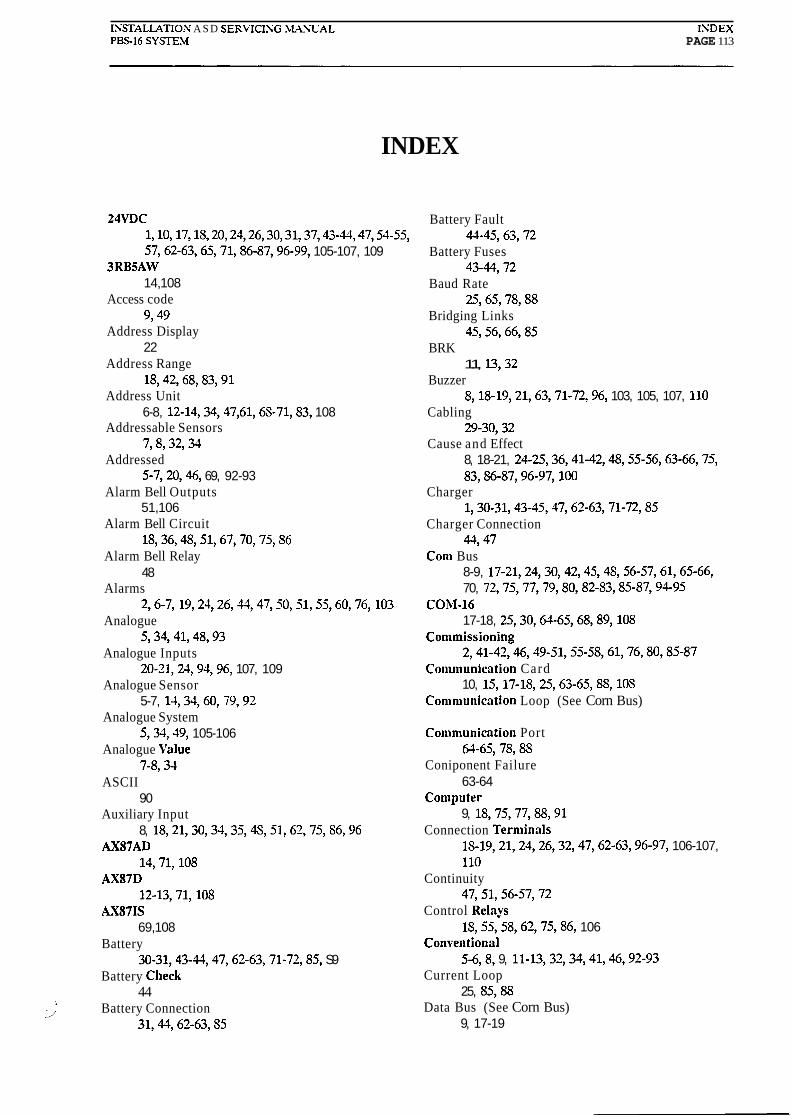
ISSTALLATIOS A S D SERVlClSG .MANUAL INDEX Pm16 SYSE.M PAGE 113
INDEX
24VDC 1,10,17,1S, 20,21,26,30,31,37,43-U, 47,5455, 57,62-63,65,71,86-87,96-99, 105-107, 109
3RBSAW 14,108
Access code 9,49
Address Display 22
Address Range 18,42,68,83,91
Address Unit 6-8, 12-14,34,47,61,6S-71,83, 108
Addressable Sensors 7,8,32,34
Addressed 5-7,20,%, 69, 92-93
Alarm Bell Outputs 51,106
Alarm Bell Circuit 18,36,4S, 51,67,70,75,SG
Alarm Bell Relay 48
Alarms 2,6-7, 19,24,26,31,47,50,51,55,60,76, 103
Analogue 5,34,41,48,93
Analogue Inputs 20-21,21,94,96. 107, 109
Analogue Sensor 5-7, 14,33,60, 79,92
Analogue System 5,33,49, 105-106
Analogue \'alue 7-8,33
ASCII 90
Auxiliary Input 8, 18,21,30,33,35,4S,51.62,75, S6,96
AXS7AD 14,71,108
AXS7D 12-13,71,1OS
LKS7IS 69,108
Battery 30-31,43-W, 47,62-63,71-72,85, S9
Battery Clieck 44
1
li Battery Connection
31,44,62-63, S5
Battery Fault 44-45,63,72
Battery Fuses 434472
Baud Rate 25,65,78,88
Bridging Links 4556, 66,85
BRK 11, 13,32
Buzzer 8,18-19,21,63,71-72,96, 103, 105, 107, 110
Cabling 29-30,32
Cause and Effect 8, 18-21, 24-25,36,41-42,48,55-56,63-66,75, 83,86-87,96-97, 100
Charger 1,30-31,43-45,47,62-63,71-72,85
Charger Connection 44,47
Con1 Bus 8-9, 17-21,24,30,42,45,4S, 56-57,61,65-66, 70, 72,75,77,79,80,82-83,8587,9495
CORI-16 17-18, 25,30,64-65,68,89, 108
Conlmissioning 2,41-42,46,49-51,55-58,61,76,80,85-87
Conl~nunication Card 10, 15, 17-18, 25,63-65, S8, 10s
Comniunication Loop (See Corn Bus)
Conlmunication Port 61-65,78,8S
Coniponent Failure 63-64
Conlputer 9, 18,75,77,88,91
Connection Terniinals 1s-19,21,24,26,32,47,62-63,96-97, 106-107, 110
Continuity 47,51,56-57,72
Control Re lay IS, 55,58,62, 7586, 106
Co~iventional 5-6,8, 9, 11-13,32,34,41,46,92-93
Current Loop 25, S5,88
Data Bus (See Corn Bus) 9, 17-19
Default 8, 18-19,31, 31,48, 51-52, 75
Detection Lines 5, 18,70, S3
Detection loops 18,47,62,68, 70,71, S3
Detector Value 48,50,63,70,79, S1
Detectors 2,5-9,ll-13,32,47-48,50,55,5S, 61-63, 68-72, 77-81,86,92-93,96,105,108
Digital 5-6,8,21,33,41,48-49,92-93,96,105-106,110
Digital System 33,105-106
DIP Switch 18-20,25,56,63-65,83-S5,8S, 103-104,lOS
Disconnect Alarm Bell Circuit 52
Disconnect Detector 50
Disconnect Loop 50
Disconnect Relays 20,53
Earth Fault 61,70
EOL Device 5-6,67
EOL Resistance 67-68
EOL Resistor 7, 11,36,51,67-72
-EPROhI 5,9, 17-21,23-25,32,56,63-66, 75, S6-SS, 92-93
Evacuate 34,75
External Buzzer 18,21,96, 110
Fault Alarm 8,35-37,49-50,60, 72,75
Fault Alarm Relay (See Fault Relay) 36-37,106
Fault Message 7,19-20,24,37,41-17,51-55,61,63,66-72
Fault Power Fuse 45
Fault Relay (See Fault Alarm Relay) 18-19,71-72, S6
Fault 6-8, 17,39,35-37,U-51,53-55,60-72, 7S,S6-87, 91,103,105-106, lOS, 112
Fire Alarms 7-5, 19,24,26,31,47,50, 52,60,75,77,81
Fire Brigade 9,21,22,49, 10s
Function 7,9, 19,34,41,41,4S-53,55, _SS, 60,66,6S-69, 71,77-81,91-91, 103
Fuse 34-35, 37,43-45,51,53,54,62-63,72,86
Gaps 21,83,100
Holes IS, 83
IF-16 20-21,23-26,63-66,86,92,96-100,109
Impedance 30,47,57,97,107, 109
!nitialisation 42,4S-49,50,68,91
Initialisation Parameters 42,49-50
Inputs 2,6-15,18,20-21,21,30,34-35,41,48,52-53, 62,61, 75,86-87,94,96-97, 107,109-110
Installation 1-3,9,29,31,3,36,43,48,60,61
Ke~board 91
Keypad 7-9,17-18,60-61,91
IiR62D 12-13,108
Lamp Test 61,65,103
Language S9,90,93
Length 17,25,30,32,80
Limits 6,31,91,97
Line 5-11,15,18,20,24,30,32-34,41-42,46-50,55, 5S,61-62, 68-71,77,80,83,86,91-95,103, 105-106
Links (See Bridging Links)
List Address Range Per Loop 91
List Detector Values 91
List Initialise Parameters 49,91
Load Resistors 43
Log 77-S2
Loop 5-11,15, lS,20,30,32-33,41-42,46-50,55, CS, 61,63,68-72,77-SO, 83,86,91-95, 103,105-106, 10s
Loop Card 17-21, 23-26,46,56,62-66,72,75,78-81,S3, S6-S7,S9,92-93,96-98,100,105-107,109-110
Loop Value 9 1

lNSTALLATION ASD SERVICISG %LASL'AL PBS-16 SYSTEM
Mains 1,31,43-45, 62,72,85,105
Mains Check 44
Mains Fault 44-45,72
Maintenance 91
Major Component Failure 63
Manual Call Points (See MCP)
Manual Control 9
Marking 5,24, 43,86-SS, 92-93
hlCP 5-7, 11-14
Rleggars 47, 51, 58
Message 7,9, 17, 19,24,35-37,4547, 49-51, 55,5S, 60-63,66-72,75,77-80,87, 103
Message Display 7, 17, 19,22,51,55, 58, 60-63,67-68,70-72,90, 103-103
Mimic Driver 20,92
Mimic Panel 24, 26, 65
Modem 78,91
hlonitoring 6-8,30-31,43-44,56, 60-61,85
blotherboard 17-20,25-26,30-31,37-38, 33-46,56, 61-68, 70-71,85436, SS, 105-107
Next Alarm 103
Nittan 11-14,32
Open Circuit 5-7,35,37,45,47,66-69,72,8h
Operator Control 7
Outputs 2,6-10, 15,lS-21,21-26,30,33-37,41-12,51-55, 58,60,62-63,71-72,75,86-87,96-102, 106, 109-110
Parameters 42,49-50,66,82,89,91, 100
Parity 89
PBS-16 1-2,5,7-10, 15, 17-IS, 24-26,31-34,37-33, 43-45,48,51,55-57,60-61,63.61,66,70,75-77,
i 80,83,85,8~-~,93,106 PRS16SA
24-26,92,105-107, 109
PBSVEW 9,49-52,57, 61, 63, 66,68-70,76-77,79-S2,S5, 8S,94
Polarity 31,3436, 43, 51,55,57,77
Port 25,61-65,76,78,88
Power Fuse 37,45
Power Supply 30-32, 43-45, 49-50, 51,57, 60, 62, 65-66, 70,72, 89
Printer 8-9, 18,25, 42, 49,54, 60, 64-65,76,78-79,88-91
Processor 5, 7,9, 17, 19,24-26,60, 63-64,78, 86-87,92-93, 100
PS-16 5,7,9, 17-19,22,25, 42, 51,57,61-68,70-72, 75, 85,8S, 90-93,105-106
Quiescent Current 94,105-109
Re-initialised 49,57
Reconnect Detector 50
Reconnect Loop 50
Relay Slave Unit 10,15, 18, 19,20, 26, 57,87, 107
Relay Unit 15, 19-20, 24-26, 57,8647, 100-102,107
Relays 7,9, 10, 15, 18-20, 26,30,42-13,55,5S, 62,75, 86-S7,96-99, 106-107
Reset 19,45,49,55,63,70,77,87,103-103
Reset Alarm 49
Resistor 6-7,20,31-32,35-36,43,46,51,67-69,71-72, 85-S6,97,107,109
Ribbon Cable 17-1S,25,62,65,B
RS-16 10, 15,20,3S, 57, 65,87,9S, 100-102,107
RS-U2C 10,15,25,76,8S
RS-31 10, 15,20,26,38,57,65,87,9S, 100-102, 109
RS-483 10,15,25,30,88
RS-S6 10, 15, 20-21, 25-26, 57,65-66,70,86-87,96-95, 100-10',110
RS-Units 10,15,20-21, 25-26,57,65-66,70,86-87,96, 97-93,100-102,110

ISSTALLATIOS ASD SERVICIXG .CL\SUAL ISDEX PBSlB SY5XE.M PAGE 116
RU-16 15, 19-21, 24, 26,63-61,83, 86,92, 96, 100-101, 107
RU-161 15,20-21,24,57,63-61,83,86,92, 94, 96, 100, 107
Safety 1
Scan 7-8,34,50,69,79
Scanning 50
Search Faults 50,91
Sensors 5-8, 13,18,32,34,42,60-61,91-93,108
Sensor Types 91
Short Circuit Isolator 32,47,68-69
Silence 19,44,77,87,103,105-106
SRP-16 15,19,87,90, 103,108
Status 6,22,33
Terminal Block 25-16,32,35-37,43-@,a, 4S, 51-56,67-68,75, 96
Test 7,20,31,41,43-45,48-50,53-57,60-61,70,76, 85,87,103
Total Power Failure 37,53-54
Uninitialised 49
US-16 5,7-8, 10, 15, 17-18,20-21,24-26,30-34,37-38, 43-35,48,55-57,61-64,70,72,75,83,85-86, S8, 93-94,96,105
\jrarranty (i), l , 112
kIratch-Dog 64
Wiring 29-32,34,36,46,51-54,65,69,72,85,87
\\'orrnald (i), 42
Zone 6-7,9,12-14,26