install manual wall mounting bracket · 4 english installation-the actual product may differ from...
TRANSCRIPT
Install Manual
Wall mounting bracket
Please read this manual carefully before operatingyour set and retain it for future reference.
OTW420B
*MFL68484541* www.lg.comP/No : MFL68484541 (1601-REV01)
2
ENG
LISH
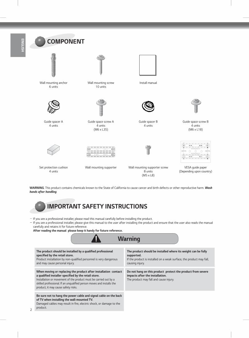
COMPONENT
Wall mounting anchor6 units
Wall mounting screw10 units
Install manual
Guide spacer A 4 units
Guide space screw A 4 units
(M6 x L35)
Guide spacer B 4 units
Guide space screw B 4 units
(M6 x L18)
Set protection cushion 4 units
Wall mounting supporter Wall mounting supporter screw 8 units
(M5 x L8)
VESA guide paper (Depending upon country)
WARNING: This product contains chemicals known to the State of California to cause cancer and birth defects or other reproductive harm. Wash hands after handling.
IMPORTANT SAFETY INSTRUCTIONS
- If you are a professional installer, please read this manual carefully before installing the product. - If you are a professional installer, please give this manual to the user after installing the product and ensure that the user also reads the manual carefully and retains it for future reference.After reading the manual, please keep it handy for future reference.
Warning
The product should be installed by a qualified professional specified by the retail store.Product installation by non-qualified personnel is very dangerous and may cause personal injury.
The product should be installed where its weight can be fully supported.If the product is installed on a weak surface, the product may fall, causing injury.
When moving or replacing the product after installation, contact a qualified installer specified by the retail store.Installation or movement of the product must be carried out by a skilled professional. If an unqualified person moves and installs the product, it may cause safety risks.
Do not hang on this product, protect the product from severe impacts after the installation. The product may fall and cause injury.
Be sure not to hang the power cable and signal cable on the back of TV when installing the wall-mounted TV. Damaged cables may result in fire, electric shock, or damage to the product.

3
ENG
LISH
Caution
Follow the instructions in this manual to protect properly. If you do not follow these instructions, the product may be installed incorrectly and cause serious injury or the product may become damaged.
To install or adjust the height of the product, two or more people are needed.If you try to install or move the product alone, it may fall and cause injury or the product may become damaged.
When installing the product, first check that the wall is strong enough. Use the anchors and screws provided. If you use anchors and screws that are not specified by the manufacturer, they may not hold the weight of the product, causing safety issues.
When drilling holes into the wall, make sure you use a drill and drill bit with the specified diameter. Ensure that you also follow the instructions regarding the depth of the holes. Otherwise, the product may be installed incorrectly and cause safety issues.
Do not clean the product with a wet towel, and do not place a heater, or humidifier beneath it. Moisture, steam or heat permeating into this product may result in fire, electric shock or product damage.
Keep this product away from sprinklers, sensors, high-tension wires and power sources. Do not install it in a location where vibrations or impacts are likely to occur.
Make sure that the power cord is removed from the outlet before installing the product.Otherwise, it may cause an electric shock or fire.
Wear safety gloves when installing the product. Do not use your bare hands.Otherwise, it may cause personal injury.
Be sure to use the accessory cable provided. Otherwise, friction between the product and the wall may cause damage to the connector. (Depending upon model.)
BEFORE INSTALLATION
* Do not use the product for purposes other than mounting a display on the wall.* When installing/using the wall mount, be cautious of product damage and avoid accidents.* If you have not fully read and understood the installation manual, do not install the product and contact the dealer to have a specialized installer
install the product for you.* Even if you are not a specialized installer, it is advantageous to have experience in mechanical or construction field in completely understanding this
manual and installing the product.* This product is designed to be mounted to walls that use standard intervals between the studs.* Install the screw to attach the wall mount so that it can be assembled at the center from both ends of the studs. Use of a stud finder, a separate
device, is recommended.* When installing the wall mount on a concrete wall or on any other wall capable of holding the strength specified in the manual, you can detach the
standard gap bracket for stud wall mounting and then follow the instructions for attaching the wall mount to make the installation easier.* Install the product only on a vertical wall.
The manufacturer is not responsible for issue from installing the product on an angled wall or on the ceiling.* Check that the accessories provided with the product are all included before installing. LG Electronics is not liable for any damage or loss of
accessories after the package has been opened.* Keep the included accessories out of reach of babies or children as it can cause safety issues including suffocation from swallowing the parts.* Make sure screws are tight against the wall, but do not overtighten.
Applying excessive force to screws may damage to the wall, affect the product performance, or cause the product to become damaged.* Be careful not to install a TV that exceeds the weight restrictions of the wall mount.* Be careful with the tools used during installation to prevent accidents or damage.
<Tools you will need> - Phillips head + driver (manual or motorized) / 8 mm socket wrench / Level / Stud finder / Drill / You may also need an Ø 4 mm drill bit for wood (or steel) or an Ø 8 mm drill bit for concrete.

4
ENG
LISH
INSTALLATION - The actual product may differ from the picture. -Consult a professional installer prior to mounting the TV using a wall bracket.
1 How to Attach the Brackets for the Product to the TV - If the screws are not fully tightened when you fix the guide spacers, check the length of the screws again.
(Only OLED55/65C6*, OLED55/65E6*, 55/65UH95**) (Only OLED55/65B6*)
Guide spacer A
Guide spacer screw A
Guide spacer B
Guide spacer screw B
(Only OLED65G6*) * Note: tighten the guide spacers after fixing the stand using the provided stand fixing screws.
1
Stand fixing screw
2Guide spacer screw B
Guide spacer B
- Work procedure1. Check to see if the display has screws installed into the mounting holes. If so, remove those.2. Assemble the guide spacer and the guide spacer screw in order as shown in the picture.
- Place the TV on a table with the screen facing down. Make sure that you place it on a flat surface covered with a soft cloth or cushion to protect it from scratches.
- Secure the guide spacers to the TV with the screws.Assemble the guide spacer to the set by tightening the screw.Tighten the screw until the set, guide spacer and the screw are fully pressing against one another.
- Use the + driver (manual or motorized) when tightening the screw.

5
ENG
LISH
2 How to attach to masonry walls
Please follow the below direction. - Check the material of the wall and the thickness of the finishing. - Use the anchors for wall material of concrete, light concrete, strong natural stone, soft natural stone masonry brick and hallow block that do not crack.
- Do not mount the device on the walls made from plasterboard or medium density fiberboard (MDF). In this case, the anchor and screws must be inserted into the concrete behind the finish surface. If there is no concrete on the other side, then you must first install a separate hanger to securely install the anchors and screws.
- When installing the product on wall material not designated, install the product so that each location can withstand the pull out load of 70 kgf (686 N) and shear load of 100 kgf (980 N) or above.
a b
d e
Wall mounting screw
c
Wall mounting anchor
- Use the Ø 8 mm drill bit for concrete and hammer (Impact) drill.a. Use a drill bit Ø 8 mm to drill a hole for the anchor location within a depth of 80 mm to 100 mm.b. Clean the drilled hole.c. Insert the sealed wall mounting anchor to the hole. (When inserting the anchor, use a hammer.)d. Set the wall mount on the wall by aligning to the location of the hole. and, set the angle adjusting part to face upward.e. Align the wall mounting screw to the hole and tighten it. Then, fasten the screws at torque of 45 kgf/cm to 60 kgf/cm.
3 How to install the wall mounting bracket
When mounting to wooden stud - Marking the Screw Fixing Spots on the Wall Using the VESA Guide Paper (Depending upon country)
1. Check the wall type before mounting. - When mounting on a wooden wall, check the screw fixing spots on the wall according to the Wall Mounting Supporter Point.
2. Mark the wall mounting location using the VESA guide paper provided.

6
ENG
LISH
a
406 mm
Drywall
Wood stud b c Drywall
Wood stud
76 mm
d
Wall mounting supporter screwWall mounting screw
a. Locate and mark the centers of the wall studs using a stud finder.b. After aligning the wall mounting bracket on the wall where the center of the wood stud is marked, mark the location of the screws and then remove
the wall mounting bracket. (Use a level to make sure your screw marks are level.)c. Use the Ø 4 mm drill bit for wood to drill holes with the depth of 76 mm or above where the wall mounting screw location is marked on the wall. (Clean the
drilled hole.)d. Tighten the wall mounting screws for the wall bracket on the drilled hole.
ʑ At this time, tighten the screw so that the wall, wall mounting bracket and the wall mounting screw are pressed against one another. (Drywall can be damaged when tightened with excessive force, please be careful.)
ʑ When tightening the screw use the + driver (manual or motorized) or 8 mm wrench.
When installing on a masonry wallKHGFEDCBA
1
2
3
4
5
6
7
8
Wall mounting screw
ʑ After aligning the wall mounting bracket to the location to install, mark the part to screw on the wall and then remove the wall mounting bracket .
ʑ Refer to next picture to attach the wall mounting bracket .
ʑ Use a level to check whether the wall mounting bracket is level.
ʑ If the screw cannot be assembled in the designated location, it can be assembled by rearranging to the closest location. But, do not change 2 or more locations from the designated spot.
ʑ Assemble the wall mounting screw on 2 left and 2 right location on the top part and 1 left and 1 right location on the bottom part.
ʑ At this time, use a + driver (manual or motorized) or 8 mm wrench to tighten the screw so that the wall, wall mounting bracket and screw are completely pressed against one another.

7
ENG
LISH
4 How to assemble the wall mounting bracket and display -Always install the display with 2 or more people.
A(2/1)
* Caution: Prevent the power cord from being pinched between the wall mounting bracket and the set when installing the set. (A pinched power cord may cause damage to the product.)
When inserting the guide spacer, align its center with the arrow shown in the figure for easy installation.
ʑ After attaching the guide spacers to the set, hang it on the wall mounting bracket in the direction of the arrows. Attach the lower part first, then attach the upper part by slightly lifting up the set.
- If the wall mounting bracket is not attached securely, the set may fall off, resulting in damage or injury. - When mounting the product that has a speaker, hold and lift up the product, not the speaker.

8
ENG
LISH
5 Setting the Lock Springs - After securing the set to the bracket, pull down the lock springs at the bottom of the wall mounting bracket.
* Caution : If the wall mounting bracket is not attached securely, the set may fall off, resulting in damage or injury.
A
1
2
3
4
5
1
2
3
4
A
1
2
3
4
5
1
2
3
4
Lock Spring
6 How to level the Display - After installing the display, check to make sure it is level. (The product goes up or down according to the rotation direction of the screw.)
± 10 mm (Leveling)
<400 x 200>
± 10 mm (Leveling)
<300 x 200>

9
ENG
LISH
7 How to Organize Cables and Attach Protective Cushions - Organize the cables as shown in the illustration. Please purchase a band for cable organization, or use the band that comes with the TV. - Attach the protective cushions to minimize the impact between the wall and the TV in case they bump against each other when adjusting the angle. Attach them in the desired positions, as illustrated.
* Caution : Prevent the power cord and the cables from being pinched between the wall mounting bracket and the wall.
Set protection cushion
10
ENG
LISH
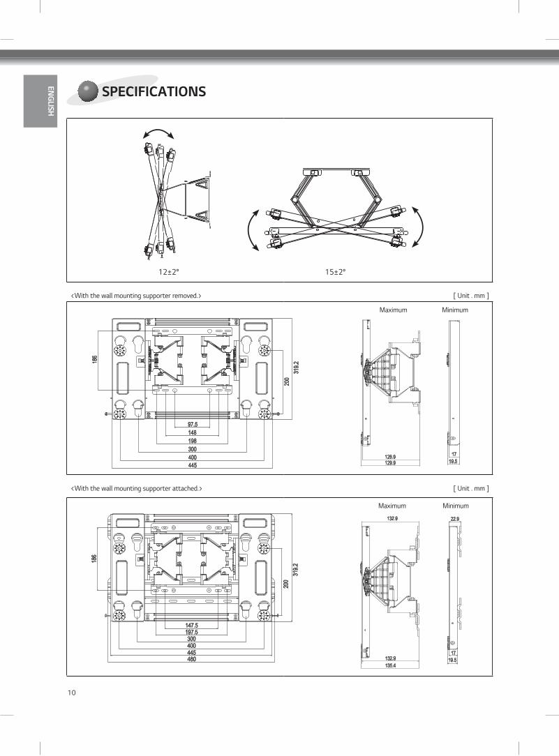
SPECIFICATIONS
107.3 24
35118.3
240
162.582.5
177.6
200
200166 234
107.3 24
35118.3
240
162.582.5
177.6
200
200166 234
12±2° 15±2°
<With the wall mounting supporter removed.> [ Unit : mm ]
97.5
186
319.2
200
148198300400445
1719.5
126.9129.9
MinimumMaximum
<With the wall mounting supporter attached.> [ Unit : mm ]
319.2
200
147.5197.5300400445460
186
1719.5132.9
135.4
132.9 22.9
MinimumMaximum
11
ENG
LISH
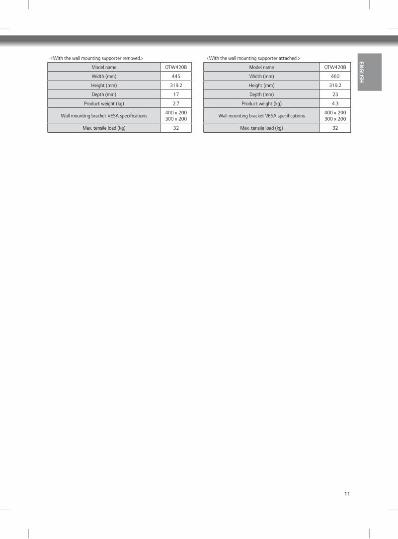
<With the wall mounting supporter removed.> <With the wall mounting supporter attached.>
Model name OTW420B Model name OTW420B
Width (mm) 445 Width (mm) 460
Height (mm) 319.2 Height (mm) 319.2
Depth (mm) 17 Depth (mm) 23
Product weight (kg) 2.7 Product weight (kg) 4.3
Wall mounting bracket VESA specifications 400 x 200300 x 200 Wall mounting bracket VESA specifications 400 x 200
300 x 200
Max. tensile load (kg) 32 Max. tensile load (kg) 32
The model and serial number of the product is located on the back or one side of the product. Record it below should you ever need service.
Supported Displays (Please contract the retailers or refer to the TV owner’s manual for applicable models.)
MODEL
SERIAL