instabus knx/eib technical manual - berker
TRANSCRIPT

INSTABUS KNX/EIB TECHNICAl mANUAlINFORM, PLAN, execute

This manual is designed to be a technical aid to electrical planning and installation. It supplements the latest issue of the master catalogue.
The manual provides advice and information based on our best current knowledge. No legal liability can be accepted for errors or omissions. Any illustrations given, including circuit and connection diagrams, are presented without guarantee, in particular in terms of product colour, size, equipment specification and features. Some of the products are protected by industrial property rights.
We reserve the right to make technical and formal changes to our products for the sake of technical development.
All products cited in this Manual subject to CE regulations carry the CE mark on their packaging label. Almost all product listed are KNX/EIB certified.
Notes on the manual Product overviews 4–11 usiNg the maNual 12–13
general information corPorate PhilosoPhy 16–17 desigN liNes 18–19 iNtro iNstabus KNX/eib 20–21
systems information techNology iNstabus KNX/eib 24–31 ets soFtware aNd bibliograPhy 32–33
Product overviews system comPoNeNts 35–67
seNsors 69–273
actuators 275–361
logic modules 363–371
visual rePreseNtatioNs 373–381
other comPoNeNts 383–399
appendix dimeNsioNal drawiNgs 401–410 glossary 411–415
traiNiNg aNd service 417 soFtware aNd data 419
Dim
. dra
win
gs
Glo
ssar
yTr
aini
ng
Ser
vice
Oth
erco
mp
one
nts
Lo
gic
mo
dul
esV
isu
al r
epre
-se
ntat
ion
sN
ote
s o
n
the
man
ual
Sys
tem
sin
form
atio
nS
yste
mco
mp
one
nts
Sen
sors
Act
uat
ors

4
PRODUCT OVERVIEWSThe two following product overviews (see also the one starting page 8) contain all of the Berker instabus KNX/EIB products currently available.
This overview is subdivided by category:
System components
Sensors
Actuators
Logic modules
Visual representations
Other components
The sequence within the individual categories is in turn subdivided into technical subgroups. The “Sensors” section, for example, includes the subgroups: Push-buttons, binary inputs, time switches, analogue inputs and other sensors.
Within the subgroups, the DIN rail mounted devices are generally listed first. Then come the built-in devices, followed by the flush and surface mounted devices.

5
Category Device RMD BI FM SM Other
System componentsPower supply Power supply 320 mA ...................................................................................... Page 36
Power supply 640 mA ...................................................................................... Page 38
Power supply 640 mA uninterruptible ............................................................. Page 40
Choke .............................................................................................................. Page 44
Coupler Coupler ............................................................................................................ Page 46
IP-Router ......................................................................................................... Page 50
Bus coupling unit Bus coupling unit ............................................................................................. Page 52
Bus coupling unit/Protective cover .................................................................. Page 54
Bus coupling unit plus/Protective cover .......................................................... Page 56
Data interface Data interface .................................................................................................. Page 58
Data interface .................................................................................................. Page 60
USB Data interface .......................................................................................... Page 62
USB Data interface .......................................................................................... Page 64
Other Data rail with connector ................................................................................... Page 66
Data rail cover .................................................................................................. Page 66
Connection terminal ......................................................................................... Page 66
SensorsPush-buttons Push-button BCU 1gang ................................................................................. Page 70
Push-button BCU 2gang ................................................................................. Page 72
Group push-button BCU 1gang ....................................................................... Page 74
Group push-button BCU 2gang ....................................................................... Page 76
Push-button 1gang .......................................................................................... Page 78
Push-button 1gang with labelling field ............................................................ Page 80
B.IQ Push-button 1gang standard ................................................................... Page 82
Push-button 1gang with labelling field and bus coupling unit (new) ................ Page 84
Glass sensor 1gang (new) ................................................................................ Page 86
Adapter for KNX/EIB and relay (new) ............................................................... Page 88
Push-button 1gang comfort............................................................................. Page 90
Push-button 1gang with labelling field ............................................................ Page 92
B.IQ Push-button 1gang comfort .................................................................... Page 94
Push-button 1gang comfort with labelling field and bus coupling unit (new) .. Page 96
Push-button 2gang .......................................................................................... Page 98
Push-button 2gang with labelling field ............................................................ Page 102
B.IQ Push-button 2gang standard ................................................................... Page 104
Push-button 2gang with labelling field and bus coupling unit (new) ................ Page 108
Glass sensor 2gang (new) ................................................................................ Page 110
KNX/EIB adapter 2 x 8gang (new) ................................................................... Page 112
Push-button 2gang comfort............................................................................. Page 114
Push-button 2gang with labelling field ............................................................ Page 116
B.IQ Push-button 2gang comfort .................................................................... Page 118
Push-button 2gang comfort with labelling field and bus coupling unit (new) .. Page 120
Push-button 3gang with labelling field ........................................................... Page 122
B.IQ Tastsensor 3gang standard ..................................................................... Page 124
Push-button 3gang with labelling field (new) ................................................... Page 126
Glass sensor 3gang (new) ................................................................................ Page 128
Push-button 3gang comfort with labelling field ............................................... Page 130
B.IQ Push-button 3gang comfort .................................................................... Page 132
Push-button 3gang with labelling field and bus coupling unit (new) ................ Page 134
Push-button 4gang .......................................................................................... Page 136
Push-button 4gang with labelling field ............................................................ Page 138
B.IQ Push-button 4gang standard ................................................................... Page 140
Push-button 4gang with labelling field and bus coupling unit (new) ................ Page 142
Glass sensor 4gang (new) ................................................................................ Page 144
Push-button 4gang comfort............................................................................. Page 146
Push-button 4gang comfort with labelling field ............................................... Page 148
B.IQ Push-button 4gang comfort .................................................................... Page 150
Push-button 4gang comfort with labelling field and bus coupling unit (new) .. Page 152
Push-button 2gang with room thermostat and display.................................... Page 154
Push-button 2gang with labelling fields, with room thermostat, display and bus coupling unit (new) ............................................................................. Page 156
Glass sensor 2gang with room thermostat (new) ............................................. Page 158
Push-button 3gang with room thermostat and display.................................... Page 160
PRODUCT OVERVIEW BY CATEGORYP
rod
ucts
continued on next pages

6
Category Device RMD BI FM SM Other
Sensors (Continued) B.IQ push-button 3gang with room thermostat and display ............................ Page 162
B.IQ IR push-button 3gang with room thermostat and display ...................... Page 164
Push-button 3gang with labelling fields, with room thermostat, display and bus coupling unit (new) ............................................................................. Page 166
Glass sensor 3gang with room thermostat (new)............................................. Page 168
B.IQ push-button 4gang with room thermostat and display ............................ Page 170
B.IQ IR push-button 4gang with room thermostat and display ...................... Page 172
Push-button 5gang with room thermostat and display.................................... Page 174
B.IQ push-button 5gang with room thermostat and display ............................ Page 176
B.IQ IR push-button 5gang with room thermostat and display ...................... Page 178
Push-button 5gang with labelling fields, with room thermostat, display and bus coupling unit (new) ............................................................................. Page 180
Light scene push-button comfort ................................................................... Page 182
Light scene push-button 8gang comfort ........................................................ Page 184
B.IQ Light scene push-button comfort ........................................................... Page 186
Push-button BCU 1gang AQUATEC ............................................................... Page 188
Group push-button BCU 1gang AQUATEC .................................................... Page 190
Push-button BCU 2gang AQUATEC ............................................................... Page 192
Group push-button BCU 2gang AQUATEC .................................................... Page 194
Physical sensors Controller sensor 180 .................................................................................... Page 196
Controller sensor 180 comfort with slide switch .............................................. Page 198
Presence detector standard ............................................................................ Page 202
Presence detector comfort ............................................................................. Page 206
Room thermostat with button interface .......................................................... Page 210
Object room thermostat with button interface ................................................. Page 214
Brightness sensor 3gang ................................................................................ Page 216
Brightness sensor 1gang ................................................................................ Page 218
Brightness and temperature sensor (new) ...................................................... Page 220
Binary inputs Binary input 4gang 230 V AC .......................................................................... Page 222
Binary input 6gang 24 V AC/DC ...................................................................... Page 224
Binary input 8gang 230 V AC .......................................................................... Page 226
Universal interface 2gang comfort .................................................................. Page 228
Universal interface 4gang comfort .................................................................. Page 232
Universal interface 8gang comfort .................................................................. Page 236
Time switches Week timer 2gang ............................................................................................ Page 238
Year timer switch 4gang .................................................................................. Page 240
Year timer switch 4gang DCF .......................................................................... Page 242
DCF receiver .................................................................................................... Page 242
Programming set for OBELISK ....................................................................... Page 242
OBELISK memory card .................................................................................... Page 242
Time transmitter .............................................................................................. Page 246
Analogue inputs Analogue input 4gang ...................................................................................... Page 248
Analogue input module 4gang ......................................................................... Page 250
Weather station (new) ...................................................................................... Page 252
Weather station 4gang comfort ....................................................................... Page 254
Power supply 24 V ........................................................................................... Page 256
Combi weather sensor ..................................................................................... Page 258
Wind sensor .................................................................................................... Page 260
Mast adapter.................................................................................................... Page 260
Rain sensor ...................................................................................................... Page 262
Brightness sensor ............................................................................................ Page 264
Temperature sensor ......................................................................................... Page 266
Twilight sensor ................................................................................................. Page 268
Other Sensor insert ................................................................................................... Page 270
Radio receiver .................................................................................................. Page 272
Pro
duc
ts

7
PRODUCT OVERVIEW BY CATEGORYP
rod
ucts Category Device RMD BI FM SM Other
ActuatorsSwitch actuators Switch actuator 2gang 16 A (new) ................................................................... Page 276
Switch actuator 4gang 16 A ........................................................................... Page 278
Switch actuator 6gang 16 A ........................................................................... Page 280
Switch actuator 8gang 16 A ........................................................................... Page 282
Switch actuator 4gang 16 A C load, current detection .................................... Page 284
Switch actuator 8gang 16 A C load, current detection .................................... Page 286
Switch actuator/shutter actuator 8/4gang 16 A NO manual ............................ Page 288
Switch actuator/shutter actuator 16/48gang 16 A NO manual ........................ Page 292
Switch actuator 1gang 16 A .............................................................................. Page 296
Switch actuator 2gang 6 A ................................................................................ Page 300
Dim actuators Universal dim actuator 1gang 50 – 500 W/VA ................................................. Page 302
Universal dim actuator 2gang 300 W/VA ......................................................... Page 304
Universal dim actuator 4gang 20 – 210 W/VA ................................................. Page 306
Universal dim actuator 1gang 210 W/VA ........................................................ Page 308
Control units Control unit 3gang 1-10 V 16 A ....................................................................... Page 312
Shutter actuators Shutter actuator 4gang 6 A 24 V DC manual ................................................... Page 314
Shutter actuator 4gang 230 V AC/2gang 12 – 48 V DC manual ........................ Page 316
Blind actuator 4gang 6 A 230 V manual .......................................................... Page 320
Shutter actuator 8gang 230 V AC/4gang 12-48 V DC manual (new) ................ Page 322
Shutter actuator 1gang 3 A (new) .................................................................... Page 324
Other Room actuator 4/2gang 16 A NO manual (new) .............................................. Page 328
Fan coil actuator 2gang 10 A NO manual (new) .............................................. Page 332
Window interface 1/1gang (new) ..................................................................... Page 336
Analogue actuator 2gang ................................................................................. Page 340
Analogue actuator module 4gang .................................................................... Page 342
Valve drive ........................................................................................................ Page 344
Programming magnet .................................................................................... Page 344
Heating actuator 6gang Triac 230 V AC ........................................................... Page 346
Heating actuator 1gang 230 V AC (new) ......................................................... Page 350
Heating actuator 6gang Triac 24 V AC ............................................................ Page 354
Heating actuator 12gang Triac 24 V AC .......................................................... Page 356
Valve drive 24 .................................................................................................. Page 358
Valve adapter ................................................................................................... Page 358
Valve drive 230 V ............................................................................................. Page 360
Valve adapter ................................................................................................... Page 360
Logic modules Logic controller ................................................................................................ Page 364
Function module .............................................................................................. Page 368
Tool software for function module full version ................................................. Page 368
Tool software for function module demo version ............................................. Page 368
Mini function module ....................................................................................... Page 370
Visual representationsDisplays Info display ..................................................................................................... Page 374
Signalling and Mini tableau MT 701 Plus ................................................................................ Page 376
operating panels Berker Master Control (new) ............................................................................ Page 378
Other components IP control (new) ................................................................................................ Page 384
DALI gateway ................................................................................................... Page 388
Bluetooth gateway .......................................................................................... Page 390
IR gateway ...................................................................................................... Page 392 Alarm central unit ............................................................................................ Page 394
Tele-control/Handset (new) .............................................................................. Page 398
Training/Service Software and Data ........................................................................................... Page 419

8
This overview allows you to access our product range quickly and easily by
order numbers
For the sake of conciseness, the individual order numbers of every design variant are not listed. The differences in the article number are indicated by the placeholder “xx”, so for example the 1gang push-button is listed under order number 7516 10 xx.
The complete article numbers of the design variants, please see the corresponding product pages.

9
Pro
duc
ts Order number Device RMD BI FM SM Other 110x ...................... Intermediate ring ........................................................................................................ Page 270
1681 xx ................. Glass sensor 1gang (new) .......................................................................................... P
1682 xx ................. Glass sensor 2gang (new) .......................................................................................... Page 110
1683 xx ................. Glass sensor 3gang (new) .......................................................................................... Page 128
1684 xx ................. Glass sensor 4gang (new) .......................................................................................... Page 144 1870 ...................... Wall box 2gang for Glass sensor (new) ...................................................................... Page 86
2766 ...................... Radio hand-held transmitter comfort ......................................................................... Page 272
2769 ...................... Radio hand-held transmitter minii .............................................................................. Page 272
7500 00 04 ............ Data rail cover ............................................................................................................ Page 66
7500 00 05 ............ Connection terminal ................................................................................................... Page 66
7500 00 07 ............ Protective cover ......................................................................................................... Page 54
7500 00 08 ............ Data rail with connector ............................................................................................. Page 66
7501 00 02 ............ Choke ........................................................................................................................ Page 44
7501 00 09 ............ Power supply 320 mA ................................................................................................ Page 36 7501 00 10 ............ Power supply 640 mA ................................................................................................ Page 38
7501 00 12 ............ USB data interface ..................................................................................................... Page 62
7501 00 13 ............ Data interface ............................................................................................................ Page 58
7501 00 15 ............ Power supply 640 mA uninterruptible (new) ............................................................. Page 40
7501 00 16 ............ IP router (new) ............................................................................................................ Page 50
7502 00 01 ............ Bus coupling unit ....................................................................................................... Page 52
7502 00 01 ............ Logic controller .......................................................................................................... Page 364
7504 00 01 ............ Bus coupling unit ....................................................................................................... Page 54
7504 00 03 ............ Bus coupling unit plus ............................................................................................... Page 56
7504 00 04 ............ USB data interface ..................................................................................................... Page 64
7506 00 xx............. Data interface ............................................................................................................ Page 60
7514 10 00 ............ Push-button BCU 1gang ........................................................................................... Page 70
7514 11 00 ............ Group push-button BCU 1gang ................................................................................. Page 74
7514 12 29 ............ Push-button 1gang with labelling field and bus coupling unit (new).......................... Page 84
7514 13 29 ............ Push-button 1gang comfort with labelling field and bus coupling unit (new) ............ Page 96
7514 20 00 ............ Push-button BCU 2gang ........................................................................................... Page 72
7514 21 00 ............ Group push-button BCU 2gang ................................................................................. Page 76
7514 22 29 ............ Push-button 2gang with labelling field and bus coupling unit (new).......................... Page 108
7514 23 29 ............ Push-button 2gang comfort with labelling field and bus coupling unit (new) ............ Page 120
7514 32 29 ............ Push-button 3gang with labelling field and bus coupling unit (new).......................... Page 126
7514 33 29 ............ Push-button 3gang comfort with labelling field and bus coupling unit (new) ............ Page134
7514 42 29 ............ Push-button 4gang with labelling field and bus coupling unit (new).......................... Page 142
7514 43 29 ............ Push-button 4gang comfort with labelling field and bus coupling unit (new) ............ Page 152
7516 10 xx............. Push-button 1gang with labelling field ...................................................................... Page 78
7516 10 9x ............ B.IQ Push-button 1gang standard ............................................................................. Page 82
7516 11 xx............. Push-button 1gang .................................................................................................... Page 78
7516 13 xx............. Push-button 1gang with labelling field ...................................................................... Page 80
7516 15 xx............. B.IQ Push-button 1gang comfort .............................................................................. Page 94
7516 16 xx............. Push-button 1gang comfort....................................................................................... Page 90
7516 17 xx............. Push-button 1gang comfort with labelling field ......................................................... Page 92
7516 20 xx............. Push-button 2gang with labelling field ...................................................................... Page 98
7516 20 9x ............ B.IQ Push-button 2gang standard ............................................................................. Page 104
7516 21 xx............. Push-button 2gang .................................................................................................... Page 98
7516 23 xx............. Push-button 2gang with labelling field ...................................................................... Page 102
7516 25 xx............. B.IQ Push-button 2gang comfort .............................................................................. Page 118
7516 26 xx............. Push-button 2gang comfort ...................................................................................... Page 114
7516 27 xx............. Push-button 2gang comfort with labelling field ......................................................... Page 116
7516 30 xx............. B.IQ Push-button 3gang standard ............................................................................. Page 124
7516 33 xx............. Push-button 3gang with labelling field ...................................................................... Page 122
7516 35 xx............. B.IQ Push-button 3gang comfort .............................................................................. Page 132
7516 37 xx............. Push-button 3gang comfort with labelling field ......................................................... Page 130
7516 40 xx............. Push-button 4gang with labelling field ...................................................................... Page 136
7516 40 9x ............ B.IQ Push-button 4gang standard ............................................................................. Page 140
7516 41 xx............. Push-button 4gang .................................................................................................... Page 136
7516 43 xx............. Push-button 4gang with labelling field ...................................................................... Page 138
7516 45 xx............. B.IQ Push-button 4gang comfort .............................................................................. Page 150
7516 46 xx............. Push-button 4gang comfort....................................................................................... Page 146
7516 47 xx............. Push-button 4gang comfort with labelling field ......................................................... Page 148
7516 86 xx............. B.IQ Light scene push-button comfort ...................................................................... Page 186
7516 87 xx............. Light scene push-button comfort .............................................................................. Page 182
PRODUCT OVERVIEW BY ORDER NUMBERS
continued on next pages

10
Pro
duc
ts Order number Device RMD BI FM SM Other7516 88 xx............. Light scene push-button 8gang comfort ................................................................... Page 184
7519 10 00 ............ Push-button BCU 1gang AQUATEC .......................................................................... Page 188
7519 11 00 ............ Group push-button BCU 1gang AQUATEC ............................................................... Page 190
7519 20 00 ............ Push-button BCU 2gang AQUATEC .......................................................................... Page 192
7519 21 00 ............ Group push-button BCU 2gang AQUATEC ............................................................... Page 194
7521 20 06 ............ Week timer 2gang ...................................................................................................... Page 238
7521 30 06 ............ Brightness sensor 3gang ........................................................................................... Page 216
7521 40 06 ............ Year timer switch 4gang DCF .................................................................................... Page 242
7521 40 07 ............ Year timer switch 4gang ............................................................................................ Page 240
7521 40 08 ............ Binary input 4gang 230 V AC ..................................................................................... Page 222
7521 60 01 ............ Binary input 6gang 24 V AC/DC ................................................................................ Page 224
7521 80 01 ............ Binary input 8gang 230 V AC ..................................................................................... Page 226
7526 11 xx ............ Controller sensor 180 (type 1.10 m) ........................................................................... Page 196
7526 12 xx ............ Controller sensor 180 (type 2.20 m) ........................................................................... Page 196
7526 15 12 ............ Controller sensor 180 comfort with slide switch (type 1.10 m) .................................. Page 198
7526 16 12 ............ Controller sensor 180 comfort with slide switch (type 2.20 m) .................................. Page 198
7526 20 01 ............ Presence detector standard ...................................................................................... Page 202
7526 40 01 ............ Presence detector comfort ........................................................................................ Page 206
7531 00 02 ............ Switch actuator/shutter actuator 16/8gang 16 A NO manual .................................... Page 292
7531 10 07 ............ Universal dim actuator 1gang 500 W/VA ................................................................... Page 302
7531 20 07 ............ Universal dim actuator 2gang 300 W/VA ................................................................... Page 304
7531 20 08 ............ Switch actuator 2gang 16 A (new) ............................................................................. Page 276
7531 20 12 ............ Fan coil actuator 2gang 10 A (new) ........................................................................... Page 332
7531 30 05 ............ Control unit 3gang 1-10 V 16 A ................................................................................. Page 312
7531 40 11 ............ Shutter actuator 4gang 6 A 24 V DC manual ............................................................. Page 314
7531 40 13 ............ Blind actuator 4gang 6 A 230 V manual .................................................................... Page 320
7531 40 15 ............ Switch actuator 4gang 16 A ...................................................................................... Page 278
7531 40 16 ............ Switch actuator 4gang 16 A C load, current detection .............................................. Page 284
7531 40 17 ............ Universal dim actuator 4gang 20-210 W/VA .............................................................. Page 306
7531 40 18 ............ Shutter actuator 4gang 230 V AC / 2gang 12-48 V DC manual .................................. Page 316
7531 40 19 ............ Room actuator 4/2gang 16 A (new) ........................................................................... Page 328
7531 60 02 ............ Switch actuator 6gang 6 A ........................................................................................ Page 280
7531 60 03 ............ Heating actuator 6gang Triac 230 V AC ..................................................................... Page 346
7531 80 03 ............ Switch actuator/shutter actuator 8/4gang 16 A NO manual ...................................... Page 288
7531 80 04 ............ Switch actuator 8gang 16 A ...................................................................................... Page 282
7531 80 05 ............ Switch actuator 8gang 16 A C load, current detection .............................................. Page 286
7531 80 08 ............ Shutter actuator 8gang 230 V AC / 4gang 12-48 V DC manual (new) ........................ Page 322
7533 00 01 ............ Heating actuator 12gang Triac 24 V AC ..................................................................... Page 356
7533 60 01 ............ Heating actuator 6gang Triac 24 V AC ....................................................................... Page 354
7534 10 01 ............ Switch actuator 1gang 16 A ...................................................................................... Page 296
7534 10 03 ............ Universal dim actuator 1gang 210 W/VA ................................................................... Page 308
7534 10 04 ............ Shutter actuator 1gang 3 A (new) .............................................................................. Page 324
7534 10 05 ............ Heating actuator 1gang 230 V AC (new) .................................................................... Page 350
7534 10 06 ............ Window interface 1/1gang (new) ............................................................................... Page 336
7534 20 01 ............ Switch actuator 2gang 6 A NO .................................................................................. Page 300
7541 40 03 ............ Weather station 4gang comfort ................................................................................. Page 254
7541 40 04 ............ Analogue input 4gang ................................................................................................ Page 248
7542 40 04 ............ Analogue input module 4gang ................................................................................... Page 248
7543 10 01 ............ Brightness sensor 1gang ........................................................................................... Page 218
7544 11 xx ............ Object room thermostat with button interface ........................................................... Page 210
7544 12 xx ............ Room thermostat with button interfacee ................................................................... Page 214 7549 00 01 ............ Weather station (new) ................................................................................................ Page 252
7549 20 02 ............ Brightness and temperature sensor (new) ................................................................. Page 220
7550 00 02 ............ Valve drive .................................................................................................................. Page 344
7551 40 01 ............ Analogue actuator 4gang ........................................................................................... Page 340
7552 40 01 ............ Analogue actuator module 4gang .............................................................................. Page 340
7563 00 04 ............ Radio receiver ............................................................................................................ Page 272
7564 20 01 ............ Universal interface 2gang comfort ............................................................................. Page 228
7564 20 3x ............ Glass sensor 2gang with room thermostat (new)....................................................... Page 158
7564 30 3x ............ Glass sensor 3gang with room thermostat (new)....................................................... Page 168
7564 40 01 .......... Universal interface 4gang comfort ............................................................................. Page 232
7564 80 01 .......... Universal interface 8gang comfort ............................................................................. Page 236
7566 01 xx ............ Bluetooth gateway ..................................................................................................... Page 390

11
PRODUCT OVERVIEW BY ORDER NUMBERSP
rod
ucts Order number Device RMD BI FM SM Other
7566 03 xx ............ IR gateway (new)........................................................................................................ Page 392
7566 27 xx ............ Push-button 2gang with room thermostat and display.............................................. Page 154
7566 27 29 ............ Push-button 2gang with labelling fields, with room thermostat, display and bus coupling unit (new) ....................................................................................... Page 156
7566 35 xx ............ B.IQ push-button 3gang with room thermostat and display ...................................... Page 162
7566 36 xx ............ B.IQ IR push-button 3gang with room thermostat and display ................................. Page 164
7566 37 xx ............ Push-button 3gang with room thermostat and display.............................................. Page 160
7566 37 29 ............ Push-button 3gang with labelling fields, with room thermostat, display and bus coupling unit (new) .............................................................................................. Page 166
7566 45 xx............. B.IQ push-button 4gang with room thermostat and display ...................................... Page 170
7566 46 xx............. B.IQ IR push-button 4gang with room thermostat and display ................................. Page 172
7566 55 xx............. B.IQ push-button 5gang with room thermostat and display ...................................... Page 176
7566 56 xx............. B.IQ IR push-button 5gang with room thermostat and display ................................. Page 178
7566 57 xx............. Push-button 5gang with room thermostat and display.............................................. Page 174
7566 57 29 ............ Push-button 5gang with labelling fields, with room thermostat, display and bus coupling unit (new) .............................................................................................. Page 180
7570 00 11 ............ Tool software for function module full version ........................................................... Page 368
7571 00 03 ............ DALI gateway ............................................................................................................. Page 388
7571 00 04 ............ IP control (new) .......................................................................................................... Page 384
7572 00 10 ............ Function module ........................................................................................................ Page 368
7572 00 11 ............ Mini function module ................................................................................................. Page 370
7573 00 10 ............ Alarm central unit ....................................................................................................... Page 394
7573 00 11 ............ Tele-control (new) ....................................................................................................... Page 398
7574 00 09 ............ Mini tableau MT 701 Plus .......................................................................................... Page 376
7574 00 1x ............ Berker Master Control (new) ...................................................................................... Page 378
7586 00 xx............. Info display ................................................................................................................ Page 374
7590 00 09 ............ Handset black ............................................................................................................ Page 398
7590 00 17 ............ Tool software for function module demo version ....................................................... Page 368
7590 00 19 ............ Programming magnet ................................................................................................ Page 344
7590 00 21 ............ Flush-mounted housing ............................................................................................. Page 376
7590 00 31 ............ KNX/EIB adapter 2 x 8gang ....................................................................................... Page 112
7590 00 32 ............ Adapter for KNX/EIB and relay .................................................................................. Page 88
7590 00 46 ............ Mast adapter .............................................................................................................. Page 260
7590 00 47 ............ DCF receiver .............................................................................................................. Page 242
7590 00 48 ............ Programming set for OBELISK .................................................................................. Page 240
7590 00 49 ............ OBELISK memory card .............................................................................................. Page 240
7590 00 50 ............ Wind sensor ............................................................................................................... Page 260
7590 00 52 ............ Rain sensor ................................................................................................................ Page 262
7590 00 53 ............ Brightness sensor ...................................................................................................... Page 264
7590 00 54 ............ Temperature sensor ................................................................................................... Page 266
7590 00 55 ............ Twilight sensor ........................................................................................................... Page 268
7590 00 57 ............ Combi weather sensor ............................................................................................... Page 254
7590 00 66 ............ Basic cable set .......................................................................................................... Page 40
7590 00 67 ............ Extension cable set .................................................................................................... Page 40
7590 00 68 ............ Lead battery 12 V....................................................................................................... Page 40
7590 00 7x ............ Valve adapter ............................................................................................................. Page 358
7590 00 80 ............ Labelling field clear transparent ................................................................................. Page 82
7590 00 81 ............ Labelling field clear transparent ................................................................................. Page 140
7590 00 82 ............ Labelling field clear transparent ................................................................................. Page 176
7591 00 01 ............ Power supply 24 V AC ............................................................................................... Page 256
7591 00 02 ............ Time transmitter ......................................................................................................... Page 246
7591 00 76 ............ Valve drive 230 V ....................................................................................................... Page 360
7591 00 77 ............ Valve drive 24 V ......................................................................................................... Page 354
7594 00 0x ............ Frame ......................................................................................................................... Page 376
7594 01 0x ............ Frame (new) ............................................................................................................... Page 378
7594 04 xx............. Central plate .............................................................................................................. Page 270
7594 10 01 ............ Sensor insert .............................................................................................................. Page 270 7596 00 xx............. Labelling field with cover plate .................................................................................. Page 79
7599 10 00 ............ Rocker grey AQUATEC .............................................................................................. Page 188
7599 11 00 ............ Rocker with lens AQUATEC ....................................................................................... Page 188
7599 12 00 ............ Rocker with imprinted symbol AQUATEC .................................................................. Page 190
7599 13 00 ............ Rocker with labelling field AQUATEC ......................................................................... Page 188
7599 20 00 ............ Rockers grey AQUATEC ............................................................................................ Page 192
7599 21 00 ............ Rockers with imprinted symbol arrow AQUATEC ...................................................... Page 192
7599 22 00 ............ Rockers with imprinted symbol arrows AQUATEC .................................................... Page 194
9200 01 ................. Emergency power storage battery ............................................................................. Page 394
12
70 71
Info
rmat
ion
Ord
er d
ata
Tec
hnic
al d
ata
The push-button BCU 1gang is executed as a flush-mounted device. It consists of a bus coupling unit, a micro push-button with associated evaluation electronics and a status LED, as well as a mechanical mounting unit for rockers.
The rockers are not included. They can be ordered separately in differing designs according to the application (1gang, with lens, with labelling).
Status LED to indicate operating states or as orientation light
Switching of a function group
Supply via bus line 21–32 V DC
Controls and displays Button with rocker mounting Programming button Programming LED Red Status LED Red
Connections KNX/EIB Terminal
Protection IP 20, EN 60529
Ambient temperature range Operation -5 to +45 °C Storage/transportation -25 to +70 °C
Mounting Fitting in wall boxes ∅ 60 mm, 40 mm deep ∅ 60 mm, 60 mm deep
Mounting orientation any
Dimensions (WxHxD) 71 x 71 x 32 mm
SENSORS
Ap
plic
atio
ns
Switching 105501 Switching functions: ON or OFF or TOGGLE LED as status indicator, continuous ON or continuous OFF
Objects 1
Group addresses/assignments maximum of 3 each
ETS search path: Berker >> Push-button >> Push-button 1gang >>
Push-button BCU 1gang
Design- with support ring ...
Rocker MODUL 2 White .......................- with lens ................- with labelling .........
Polar white ..............- with lens ................- with labelling .........
7514 10 00
1620 021621 121626 02
1620 091621 191626 09
Rocker Berker S.1/B.1/B.3/B.7 GLASWhite, glossy ...........- with lens ................- with labelling .........
Polar white, glossy- with lens ................- with labelling .........
Polar white, matt .....- with lens ................- with labelling .........
Rocker Berker S.1/B.1/B.3/B.7 GLASAnthracite, matt .......- with lens ................- with labelling .........
Aluminium, matt ......- with lens ................- with labelling .........
Rocker Berker K.1/K.5White .......................- with lens ................- with labelling .........
Polar white ..............- with lens ................- with labelling .........
Anthracite, matt .......- with lens ................- with labelling .........
Aluminium, matt ......- with lens ................- with labelling .........
1405 70 021415 70 021426 70 02
1405 70 091415 70 091426 70 09
1405 70 061415 70 061426 70 06
1405 70 241415 70 241426 70 24
1620 16 061621 16 061626 16 06
1620 14 041621 14 041626 14 04
1620 89 821621 89 821626 89 82
1620 89 891621 89 891626 89 89
1620 19 091621 19 091626 19 09
Rocker Berker K.1/K.5Stainless steel .........- with lens ................- with labelling .........
1405 70 041415 70 041426 70 04
Rocker Berker ARSYSWhite .......................- with lens ................- with labelling .........
Polar white ..............- with lens ................- with labelling .........
Light bronze, metal ...- with lens ................- with labelling .........
Stainless steel .........- with lens ................- with labelling .........
1405 00 021415 00 021426 00 02
1405 00 691415 00 691426 00 69
1404 00 011416 00 011436 00 01
1404 00 041416 00 041436 00 04
RockerShatter-proof IP 44White- with lens ................- with labelling .........
Polar white- with lens ................- with labelling .........
155015531629
1550 091553 091629 09
Ro
cker
s
Rocker Rocker with lens Rocker with labelling
1
248 249
Info
rmat
ion
4
Ord
er d
ata
Tec
hnic
al d
ata
The analogue input 4gang is designed as a top hat rail mounted device and is used to acquire and forward up to four analogue sensor signals. The analogue input can evaluate both voltage and current signals. The current inputs with the measurement range 4–20mA can be monitored for wire break.
Sensor signals are converted into 1-byte or 2-byte value telegrams. Two limit values can be set per sensor; these can trigger measured-value dependent events, such as control of shutters and blinds, switching exterior lighting, etc. By means of external objects it is possible to adapt all of the limit values while operation continues, e. g. via KNX/EIB devices such as information display or MT 701 plus or MT 701 ct. Operation of the analogue input requires a 24 V auxiliary voltage. External analogue sensors are supplied with voltage via the short-circuit and overload protected outputs.
The lateral interface can be used to connect an analogue input module for another 4 sensors, which are likewise adjusted via the software of the basic unit.
Four freely adjustable sensor inputs
Four additional sensor inputs possible using analogue input module
Conversion of analogue measurement data into 1-byte and 2-byte values (EIS 5/6)
System interface for connection of an analogue input module
24 V DC output for supplying connected sensors
Analogue input 4gang
Supply via bus line 21– 32 V DC
Auxiliary voltage 24 V AC ± 10 % SELV Current input max. 250 mA
Inputs Sensor inputs 4 Current 0–20 mA, 4–20 mA Voltage 0–1 V, 0–10 V Input resistance Voltage measurement approx. 18 kOhm Current measurement approx. 100 ohm
Outputs Supply outputs 2 Rated voltage 24 V AC ±10 % Maximum current 100 mA DC total
Behaviour in the event of power failure Bus voltage failure no communication with KNX/EIB Supply voltage failure no communication with KNX/EIB, no supply for the sensors
Behaviour in the event of power return Bus voltage no communication with KNX/EIB, no supply for the sensors Supply voltage no communication with KNX/EIB Bus and supply voltage Transmission of the measurement and limit values as per initialisation parameters of the application
Operation and display elements Programming key Programming LED Red Status LED Red/green
Connections KNX/EIB Connecting terminal Inputs 0.5–4 mm² single/finely stranded without conductor sleeve, 0.5–2.5 mm² finely stranded with conductor sleeve Module connection 6pole system plug for analogue input module
Protection IP 20, EN 60529
Ambient temperature range Operation -5 to +45 °C Storage/transport -25 to +70 °C
Dimensions (W x H x D) 72 x 90 x 58 mm 4 modules
SENSORS
Ap
plic
atio
ns
Analogue input 4gang V2 B00A01Analogue inputs Connectable sensor type can be adjusted for the integral analogue inputs: 0–1 V; 0–10 V; 0–20 mA; 4–20 mA Transmission behaviour for measured values adjustable 1 or 2-byte can be chosen as transmission format Two limit values with hysteresis can be set per input Two external limit values per input can be selected for adjustment via EIB devices in ongoing operation Wire break monitoring can be set for 4–20 mA sensors Transmission of an alarm bit can be set
Modules One analogue input module with four additional inputs can be selected: Programming options are the same as the basic unit
Objects 50
Group addresses/assignments max. 200 each
Device colourLight grey ................ 7541 40 04
No
tes
AccessoriesAnalogue input module ....................
Power supply 24 V AC ...................
7542 40 04
7591 00 01
Key1. Analogue input module
connection 2. Bus connection 3. Programming button 4. Programming LED 5. Status LED6. Active sensor
Terminals+US: Supply for external
sensorsGND: Reference potential for
+US and inputsE1…E4: Measured value inputsAC 24 V: External supply
voltage2
134
56
Product example without design variants
Product example with design variants
1
2
3
5
4
6
8
13
9
15
10
14
7
11
12

13
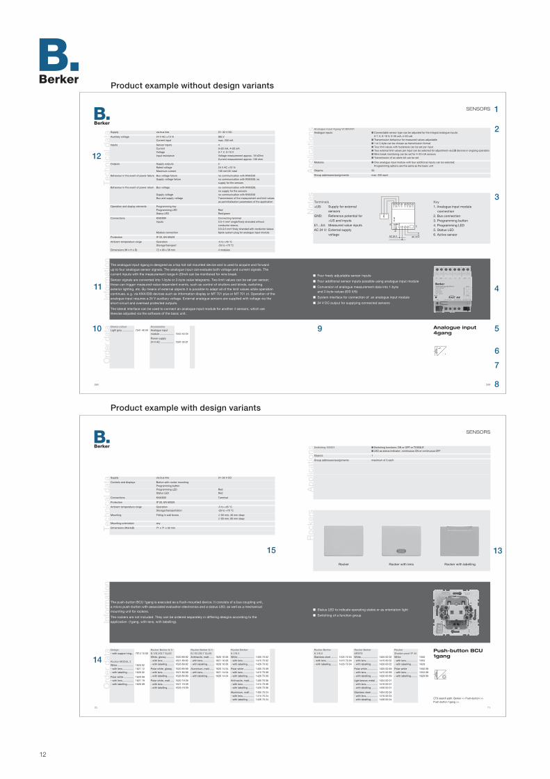
USING THE MANUALIn
form
atio
n Double-page layoutProduct descriptions are always laid out across a double page. On the left, two typical examples are illustrated. The blue item numbers are pointers which allow you to access key information such as technical data, applications, com-bination options, order numbers and suchlike quickly and easily.
1 Device categoryThe device category is indicated at the top right as a quick reference guide – in this case “Sensors”.
2 Applications Any applications linked to the device are presented here with their name, features, number of objects, group addresses and assignments. If you would like more detailed information, e.g. about the objects, it is available on the Internet under "www.berker.com".
3 NotesDepending on the device, this segment will give details of special features, such as for installation. There will also usually be a specimen schematic connection diagram, with a key to the connec-tions, controls and displays, electri-cal consumers, etc. shown.
4 Product illustration The core element of the page lay-out is the full-width blue “viewing window” (shown here in dark grey for the sake of clarity). It contains the product descriptions (see 9 and 11) and the product illustration, which is always presented on the right-hand side within the viewing window.
IMPORTANTProduct illustrations are generally shown in halftones. For more colour and shape details, refer to our master catalogue.
5 Product nameThe product name is important for communication between the various technical specialists. For ordering purposes, however, only the order number is unique.
6 ETS iconThe ETS icon provides quick classification of the device, and can be inserted into block diagrams, planning sketches, etc.
7 ETS search pathThe relevant “device path” is entered here for planning/installation using the ETS2 software package.
8 Number of pagesQuick access to the product descrip-tions by way of the table of contents on pages 4 –11.
9 Key featuresThis segment gives a bullet-pointed listing of the key features of the product concerned. It is supple-mented by the features information (also white-bulleted) listed in the “viewing window” (see 11).
10 Ordering dataIn this example there is only one version of the device. For planning purposes, this segment provides you with details of the order number as well as the product colour.
11 InformationThis segment provides supplemen-tary information on the key features listing, including details such as the device type, area of application, func-tionality and combination options.
12 Technical dataThis segment presents all the key technical specifications for power supply, inputs and outputs, controls and displays, protection and ambient temperature range.
13 AccessoriesIn many catalogues the accessories are listed on separate pages. For the sake of clarity, wherever possible the accessories are specified directly together with the product concerned. This example shows the rockers which can be combined with the push-button BCU 2gang.
14 Complex ordering dataThe information given is generally the same as under item 10. Our range of design lines is listed apart from BERKER S.1 up to MODUL 2. Where the product in question has different design versions (such as different-acting types of monitor sensors), the relevant ordering data for the variants is also listed directly here. Thus, in the example here the ordering data includes “shatter-proof IP 44 rockers”.
15 (where appropriate containing the following indication)“continued on next double page ”The double-page product description is laid out as follows:– technical data always at the top left– applications always at the top right
The descriptions of some devices are so lengthy that they require an additional double page. In such cases the continuation of the “Technical data” will not, as when reading normally, follow on at the right, but will resume on the next double page. The same applies to the application descriptions, though they are always to be found at the top right.

14

15
Corporate philosophy 16–17Design lines 18–19Intro instabus KNX/EIB 20–21
GENERAL INFORMATION
Berker sets standards in design and functionality. With design
concepts tailored to the needs of individual comfort. This means
that you can combine all of the colour and material variants
within these series with the flush-mounted inserts in the manner
of a modular system. This gives you maximum flexibility and
rigorously integrated design for all applications.
From simple socket outlets to innovative control sections – the
modular system from Berker offers complete options for modern,
flexible electrical installations. Thus it is possible to exchange the
surfaces later – even after many years.
Berker switch systems – safe, future-proof
and quality “Made in Germany”.
Dim
. dra
win
gs
Glo
ssar
yTr
aini
ng
Ser
vice
Oth
erco
mp
one
nts
Lo
gic
mo
dul
esV
isu
al r
epre
-se
ntat
ion
sS
yste
ms
info
rmat
ion
Sys
tem
com
po
nent
sS
enso
rsA
ctu
ato
rs

16
1919.The Berker brothers establish a specialist factory for electrical appliances in Schalks -mühle, Germany. Success is not long in coming. After only two years‘ production, the small operation reaches its capacity limits. Reason enough, as early as 1921, to open a second production facility in Ottfingen.Concentrated investments in building, assembly and production facilities help the company to become a leading vendor of switches and system within just a few years.
BERKER TODAY.Our headquarters is still in Schalksmühle, Germany, where the company was founded. At its Ottfingen plant, Berker has state-of-the-art manufacturing facilities for switches and systems, a central warehouse, and a KNX/EIB training and information centre.

17
CORPORATE PHILOSOPHY
Berker sets standards in design and functionality. This is attested by the innovative instabus KNX/EIB concepts, which
rely on a very high degree of technology and combination options.
In order to achieve our goals, we work closely with the Konnex (KNX) umbrella organisation and with the best designers and developers.
Our slogan for the 21st century: “Berker – the right way.” Our future-oriented corporate philosophy is matched
by our state-of-the-art production processes.
Concentrated investment has built the company rapidly into a leading supplier in its field. Advanced computer-aided methods are
applied to develop and design state-of-the-art products that correspond to the latest technical advances such
as instabus KNX/EIB technology.
The focus is on the quality and safety of the finished products. Berker was one of the first companies to install a quality
management system to DIN ISO 9001, meeting all the requirements for certification.
The quality of Berker‘s products very soon became known not only in Germany, but also in the rest of Europe and overseas.
Holdings in other electrical and electronics engineering companies also permit Berker to benefit from cross-product
technology transfer and open up new opportunities on the market.
Whether in residential buildings, congress centres, museums, or even in mobile homes – Berker products are in use all over the world.
We will be pleased to make our know-how available to you too.

18
BERKER SWITCH RANGESAll Berker flush-mounted standard and area programs are modular in design. This means they can combine all the colour and material variants within the various ranges according to individual needs. And of course you can also interchange surfaces within the Berker special ranges.
MODUL 2The standard program combines highly flexible design options with optimum value for money: A classic range matching any interior design style, specially suited to rented apartment blocks and public buildings as well as private living space.
Berker S.1The Berker S.1 standard range sets new standards in many respects. The modern design with its simple elegance is suitable for a wide variety of ambiences and intended uses. Using the same rockers and inserts in the ranges Berker S.1, B.1, B.3 and B.7 GLAS means that warehousing requirements are minimised. Its modular concept, ergonomic design and square shape guarantee efficient handling.
Berker B.1, B.3 and B.7 GLASThe pure brilliance of the B. switch series lends your room a timeless elegance. Thanks to the successful symbiosis of shape, material and colour, the switch ranges B.1, B.3 and B.7 are perfectly designed to meet your requirements. The gentle metallic gleam of the Berker B.3 in real aluminium is truly impressive, and the clear design of the Berker B.7 GLASS fits in perfectly with the most diverse interior styles.
Berker S.1 Berker B.1MODUL 2 Berker B.3 Berker B.7 GLAS

19
DESIGN LINES
Berker Q.1With its unmistakeable features, the new Berker Q.1 will inspire and excite all those who
are searching for switches with a wide range of applications. It features a unique velvety surface made of polar white plastic. Its pleasing shape and soft, rounded contours are like love at first sight.
Berker K.1 and K.5Sharp edges and square corners. Linear balance, while renouncing all other design attributes:
those are the salient design features of the Berker K.1 range. With its new interpretation of timeless design sensibilities, the Berker K.1 gives your interior spaces a clear, linear, timeless character.
Clear contours. Consistent design. A cultivated exterior–the Berker K.5 is recommended for anyone who values fine forms and the highest quality materials in stainless steel, all in equal measure.
ARSYSPerfect interior design originates in the detail. Carefully selected materials and colour shades create
the foundation for harmonious design of living and working spaces. The program ARSYS offers you a wide variety of materials, elegant forms and colours, from classic white to shimmering
matt stainless steel – a byword for timeless design.
B.IQB.IQ is a minimalist design through and through. A frameless switch with a large contact area and
a striking indicator light in the centre are perfectly enhanced by the high quality materials: glass, brushed stainless steel and plastic in polar white.
TS SENSORA smooth glass surface conceals the innovative technology - push-buttons that perform
functions at a gentle touch, and a display in “dark design” for the room temperature control. The Berker TS Sensor – the ideal solution for especially sophisticated requirements.
Berker K.1 Berker ARSYSBerker Q.1 B.IQ TS Sensor

20
CONVENTIONAL ELECTRICAL INSTALLATIONThe electrical installation field faces ever increasing demands. For example, information and data relating to the individual subsystems (heating/lighting/window blinds) within an overall facility increasingly needs to be exchanged and modified according to specific requirements. This is especially true of office blocks, warehousing and factory facilities of all kinds, and hotels and leisure facilities, in which conventional installation needs to be supplemented by the whole raft of modern-day state-of-the-art communications technology. And complex new demands are arising in the residential building sector too. As a result, conventional electrical installation is becoming more and more technically complicated, costly and complex.
The greater demands are increasingly difficult to meet on any commercially viable basis using conventional installation techniques. Consequently, it makes sense right from the planning phase to consider alternative techniques such as the instabus KNX/EIB system technology, which makes all the necessary connections, allows for unproblematic modifications as and when required, and is oriented to future needs.
HISTORY OF INSTABUS KNX/EIBAt the end of the 1980s Berker together with other leading electrical engineering companies formed an instabus development group. The outcome, in 1990, was the EIBA – the European Installation Bus Association.All newly developed KNX/EIB products are developed, tested and monitored by Konnex (KNX) in compliance with the applicable standards. If a product meets all the relevant standards, it is awarded Konnex (KNX) certification. This ensures that all KNX/EIB components are able to communicate with each other and have the same system design.
INNOVATIVE BUILDING SYSTEM TECHNOLOGYThe European Installation Bus – KNX/EIB – is a standardised installation system providing automated control of technical functions in commercial, public and residential buildings. KNX/EIB benefits personal safety and protects property, ensures efficient use of energy and enhances comfort. The system also considerably reduces the time and cost involved in instal-lation. All subsystems can be integrated over the bus, from the lighting to the alarm system, from the central heating to the window blind management system. KNX/EIB is even capable of operating specific appliances such as ovens, washing machines and irons. In terms of pro-ducts the consumer has a full spectrum of choice, because over a hundred leading manufac-turers offer KNX/EIB-compatible appliances. Thus the number of private and public clients deciding in favour of installing KNX/EIB is increasing by several thousand each year.
KNX/EIB is suitable for installation in detached homes and apartment blocks, offices and other business premises, as well as in light commercial and industrial buildings, hotels, banks, schools, hospitals and a range of other public and commercial buildings. It can be used to

21
INTRO INSTAbuS KNX/EIb
control the heating, air conditioning, ventilation, lighting, window blinds and shutters, as well as to monitor and report technical building services functions, for load management, alarm signalling,
remote control and remote monitoring purposes.
Whether in a bank tower in London, a hotel in Amsterdam or a private apartment block in Düsseldorf – KNX/EIB provides efficient management of private, public and commercial buildings
on a worldwide scale, substantially cutting the cost of use of any property based on timed and presence-sensitive operation of appliances and systems. Oriented towards people’s personal sense of well-being, the KNX/EIB system technology also increases productivity. It adapts the climate control of
interior spaces to the weather, and creates a constant, comfortable atmosphere within the building. And installing KNX/EIB is worthwhile not least for safety reasons too. At minimal material cost,
the risk of fire is significantly reduced relative to a conventional installation.
USER-FRIENDLY – COST-SAVINGThe KNX/EIB building system can be tailored precisely to the needs of the specific users, and responds
to users‘ requirements in terms of ease of use. All of the building services functions of a KNX/EIB system are coordinated with each other and with the ambient conditions. Thus the lighting, heating and air con-
ditioning are adapted to the actual current demands without the need for any reduction in comfort. Load management and efficient use of energy result in substantial savings in terms of operating cost.
Subsequent changes of use and conversions can be carried out more quickly and cost-effectively. Investments in KNX/EIB are amortized within just a few years.
TIME-SAVING – SAFE – FLEXIBLEThe time commitment and expense of planning and installation is reduced. This is made possible by
software support in the planning and commissioning of KNX/EIB systems. And there is much less wiring too. The power cables are routed only to the electrical loads, and not to the sensors (push-
buttons, switches, thermostats, etc.). The reduced wiring complexity also means less fire risk.Changes of use as commonly occur in modern office and business environments place
high demands on the electrical installation, but are no problem for KNX/EIB. With no additional installation work, functions can be modified by readdressing and parameter
resetting (with software support) of the KNX/EIB components.
MODULAR – UPGRADABLE – COMPATIBLEThe modular, decentralized design of the KNX/EIB building system prevents any malfunctions
which may occur from interfering with the functioning of the overall system. Additions, renovations and extensions can be connected to the existing KNX/EIB installations
at any time, even between buildings. KNX/EIB systems can be connected via interfaces to building control and automation systems and so perform additional functions.

22

23
Example: Office/Home 24–25instabus KNX/EIB technology 26–31ETS software 32Bibliography 33
SYSTEM INFORMATION
The idea of being able to control every conceivable electrical appliance and system in the building from virtually any centralized location, or
indeed from decentralized multiple locations, has long occupied the minds of electrical engineers.
This desire for a user-friendly building system was the trigger which led to the establishment of the European Installation Bus as the standard for
intelligent building control in modern installation engineering.
The instabus KNX/EIB meets all the requirements placed on such a system: Simple installation and commissioning, flexibility, cost-effectiveness,
high operational safety, comfort and user-friendliness
This section presents a brief introduction to the instabus KNX/EIB system.
Dim
. dra
win
gs
Glo
ssar
yTr
aini
ng
Ser
vice
Oth
erco
mp
one
nts
Lo
gic
mo
dul
esV
isu
al r
epre
-se
ntat
ion
sS
yste
mco
mp
one
nts
Sen
sors
Act
uat
ors
Sys
tem
sin
form
atio
n

24
Ap
plic
atio
n ex
amp
les
“Office”
1
2
3
4
5
“Home”
11
6
712
8
10
9
7
66
6
6
10

25
EXAMPLE: OFFICE/HOMEIn
form
atio
n “Office”In today‘s world, the commercial use of a building essentially depends on factors such as flexibility, transparency, function-ality and energy management. A state-of-the-art electrical installation using the Berker instabus KNX/EIB system provides the ideal basis for integration of the overall building systems.
1 Lighting Ambient light sensitive lighting control; constant light regulation at the workplace; needs-based light-ing (light scenes, monitors)
2 Sun shade/blinds/shuttersAutomatic light/sun shading; safe-ty functions to prevent destruction by wind, rain and frost
3 Heating/air conditioning/ ventilation Energy saving based on needs-oriented room-by-room control; comfort/standby/night modes; timed temperature profiling; heat-ing and cooling with a thermostat; controlled air supply and venting; incorporation of boiler control
4 Security Fault signalling; surveillance devices; fire alarms
5 General functions Presentation/visualisation of building functions on panel and PC; metre, consumption and operating hours data acquisition; centralised control of building functions; maximum building transparency; timer-controlled building functions;
communication; remote visualisation and surveillance; remote mainte-nance; transmission of operating states and alarms
“Home”Demands for security, comfort and well-being in the private residential environment are rising continuously. Of increasing importance in this re-gard is the cost-effective overall use of the building. All these demands can be met with a state-of-the-art electrical wiring installation. The Berk-er instabus KNX/EIB installation bus system provides the ideal basis.
6 Lighting Store and retrieve lighting moods/light scenes at the press of a button; operate/dim lights individually, in groups and centrally; needs-based lighting (monitors); reduction in number of control elements; switch-able sockets for portable devices
7 Sun shade/blinds/shuttersAutomatic sun shade function; timed window blind functions
8 Weather device Protection of awnings and blinds against destruction by wind, rain and frost; automatic closure of skylight windows in event of rain; display of weather data (wind speed, rain, temperature and brightness)
9 HeatingWell-being based on differing temperature zones around the house; energy saving based on needs- oriented room-by-room control; timed temperature profiling; incorporation of boiler control and circulation pump
10 Security Processing of fault signals (power failure/heating malfunction/freezer/washing machine etc.); presence simulation by automatic lighting and window blind control; motion- sensitive exterior lighting; monitoring of opening of windows, doors and gates; interior surveillance (monitors); fire alarm systems; telephone for-warding of fault and alarm signals; telephone status polling; panic button with custom functioning; integrated closure systems
11 Alarm central unitMonitoring of opening of windows, doors and gates; interior space moni-toring (controllers); fire alarm systems; raising the alarm; communicating faults and alarms by telephone; re-sponding to telephoned status enqui-ries; integrated closing systems; lin-king alarm and installation functions
12 General functions Timed operation (lighting/heating/window blinds); wireless remote control of in-house functions; group and centralised functions; centralised display and operator control units; absence mode (“sleeping house”)
CommunicationTelephone status polling/ fault signallingRemote maintenance

26
Info
rmat
ion
Continued on next double page
The diagram shows a schematic example segment of an instabus KNX/EIB system.
AC = Area couplerAL = Area lineML = Main lineL = LineLC = Line couplerPS = Power supplyDEV = Device (sensor/actuator)
INSTABUS KNX/EIB BASICS instabus KNX/EIB is a standardized, decentralized bus system. Devices can interchange in formation directly over the bus – that is, without going via a central control unit. All the devices on the bus have equal rights status (multi-master mode).
The key components of an instabus KNX/EIB installation are the two-wire bus cable and the bus-compatible devices, such as system devices (e. g. power supply units, couplers, inter-faces), sensors (e.g. push-buttons, binary inputs) and actuators (e. g. switch actuators, valve drives, etc.). Data is exchanged between sensors (transmitter) and actuators (receiver/converter) over the bus cable in the form of data telegrams.
Communication and power supply to the device electronics is carried over the bus cable, which is connected to each device. In contrast to the sensors, the actuators usually require an addi-tional supply voltage (230 V) to control the consumers. The bus cable and the mains power connection are reliably isolated from each other.
The bus coupling units of the respective sensors/actuators (devices) perform other core func-tions in the instabus KNX/EIB system in addition to receiving and sending data: they store the physical address, the group addresses and the applications “management”. The applications are grouped in the Berker product database.
This information is loaded to the bus coupling unit via a PC with a serial or USB interface and the bus. Configuration and commissioning is carried out using the EIB tool software ETS2 or ETS3.
AL: to more areas (max. 15 in total)
~
=
~
=
~
=
MLLC1 LC2
ACPS
PS PSDEV
DEV
DEV
LLDEV

27
INSTAbuS KNX/EIb TECHNOLOgYS
yste
mS
enso
rsA
ctua
tors
The diagram shows examples of various device types of an instabus KNX/EIB line.
Actuators Lighting Drives Shutters/blinds Heating/air conditioning/ ventilation
Sensors Wind, motion, light Push-button Controller
Couplers (sample illustration for system devices) Programming by means of programming button and LED Connection of lines and areas (connecting terminals) Reduction of telegram traffic on bus through filter functions when used as a line or area coupler Amplification of lines and assignment of independent line segments
Push-button 4gang comfort (sample illustration for sensors)
Bus coupling unit required Program-specific information processing Device-specific features such as light scene retrieval Reception and forwarding of information such as switching commands and measurement variables to the actuators User module with application (software) determines the device function, e.g. of a push-button
Switch actuator 4gang (sample illustration for actuators)
Bus coupling unit In some cases mains voltage (230 V) required Telegram-specific information processing Device-specific features such as local operation, potentiometer, etc. Reception of information sent by sensors Conversion of the commands into actions, e.g. switching, dimming, etc.
KNX/EIB
230 V ~

28
INSTABUS KNX/EIB TOPOLOGYThe instabus KNX/EIB is divided into hierarchical segments. The smallest unit is the line. A line comprises a maximum of 256 bus devices (DEV) and at least one power supply unit (PS) with choke. By means of line couplers (LC) interconnected via a main line, up to 15 lines can be coupled. The result of this is an area.
14 additional areas are available to upgrade an instabus KNX/EIB system. An area line inter-connects all 15 areas by means of area couplers (AC). The main and area lines also require a power supply unit with choke.
The line-and-area structuring means that the data transfer of a line or area does not influence the data flow of other lines or areas. A line coupler filters the data flow by ignoring telegrams from other lines/areas which do not address any devices within its own line. This also permits independent communication within multiple lines. The same also applies to the area couplers.
When all lines and areas are in use, over 61,000 devices can be connected to the instabus KNX/EIB system.
INSTABUS KNX/EIB ADDRESSINGWith such a multiplicity of devices, two conditions in particular need to be met:
Security of data transfer
Unique and complex addressability of the individual devices
The bus voltage is 21–32 V DC. The data transfer rate is 9.6 kBit/s, so terminators are not required. To avoid telegram collisions, the CSMA/CA procedure is applied.
In addressing, a distinction is made between the physical address and the group address. The physical address reflects the name of the bus device and has the following format: “area.line.device” (e. g. 2.5.11). The physical address is used in programming and diagnosis. The group address indicates the relationship between the devices on the bus. The group address is divided into a maximum of 15 main groups each with a maximum of 2048 sub-groups. It is maintained in the format: “main group/subgroup” (e. g. 1/955) or “main group/ secondary group/subgroup” (e. g. 1/3/125). Usually the group address is used to control the individual instabus KNX/EIB devices.

29
INSTAbuS KNX/EIb TECHNOLOgY W
iring
Cable selection/exteriorOnly bus cables of which the cores are encased in a common sheath may be used. The bus cables must be rated for at least the same test voltage between the conductor and the cable surface as applies to power lines.
The following cable types are usable (see also KNX/EIB technical data):– YCYM 2x2x0.8 or– J-Y(St)Y 2x2x0.8
Type YCYM may only be used in exterior applications if the cable is protected against the effects of heat (direct sunlight, etc.). Otherwise type J-Y(St)Y should be chosen.
If an instabus KNX/EIB connection between two buildings is required, the KNX/EIB bus cable can be used provided it is laid in a con-duit. Water build-up in the conduit must be avoided.
Cables/wiringThe instabus KNX/EIB devices are interconnected in parallel via one wire pair (black/red) of the four-core bus cable, by way of terminals.
Use of the free wire pair on the KNX/EIB cable for additional applications is subject to the following conditions:– Safety/protective extra low
voltage (SELV/PELV) only– Max. 2.5 mA continuous current
Overcurrent protection required– Voice transmission permitted;
not as public telephone line (FTZ 731 TR 1)
– Unique marking of instabus KNX/EIB cables
We recommend marking the selected application clearly on all cable ends.
Use of the free wire pair within a line must be uniform. If the two uncon-nected cables (normally yellow/white) are used as an additional KNX/EIB bus line, then the yellow cable should be used as bus voltage + and the white cable as bus voltage –.
Unused wire pairs and filler wire should be rolled up or tied back. Free wires and the filler must never be allowed to touch live parts or earth.
StructuresWithin a line, the wiring options can be chosen from the following struc-tures and combined at will. A loop structure is not permitted.
Line structure Star structure Tree structure

30
KN
X/E
IB t
echn
ical
dat
aK
NX
/EIB
sta
ndar
ds
Functions Display, dimming, management, signalling, measurement, closed-loop control, switching, open-loop control, monitoring
Transmission technique Serial telegram transfer Time multiplex 2-wire mode Symmetrical transfer
Transfer rate 9600 bit/s
Interference immunity to prEN 50082-2 Tested 2kV surge voltage DIN VDE 0845 part 1 DIN EN 50082 part 2
Protection Safety extra low voltage (SELV) to DIN VDE 0100 T410
Power supply 230 V AC / 24 DC Short-circuit-proof
Rated system voltage 24 V DC
Current consumption per device max. 6.25 mA (150 mW)
Number of devices with 640 mA power supply max. 100
Devices per line max. 255 (additional power supply units and couplers required as line amplifiers)
Lines per area max. 15 plus main line
Line interconnection via area/line coupler
Areas max. 15
Bus cable YCYM 2x2x0.8 to EIBA guideline, DIN VDE 0207 and 0815 J-Y(St)Y 2x2x0.8 to DIN VDE 0815
Wire cores Red (+KNX/EIB) and black (–KNX/EIB) Yellow and white (each free)
Wiring Surface/flush mounted In duct
In conduit together with NYM with no clearance to flat webbed building wire min. 10 mm clearance
Cable length max. 1000 m
Clearance from device to power supply max. 350 m between two devices max. 700 m between two power supply units with integ. choke min. 200 m
System configurations Line, star and tree configurations Combinable at will – no loops
Component designs RMD, built-in, flush-mounted, surface-mounted and duct
Bus management decentralized Devices equal status Access method CSMA/CA
Addressing Physical address Continuous Group address by collective function assignment
E DIN VDE 31000 part 10 General principles for safe design of technical products
VDE 1000 part 10 Requirements for electrical engineering personnel
DIN VDE 0100 Construction of power systems with rated voltages up to 1000 V– T200 General terms– T410 Protective measures Protection against electric shock– T420 Protective measures Protection against overheating– T430 Protective measures Protection of cables and wires– T510 Selection/construction of electrical equipment General points– T510 Selection/construction of electrical equipment Cables, wires, busbars– T610 Initial testing– T725 Auxiliary circuits
DIN VDE 0105 part 1 Operation of power systems General specifications
DIN VDE 0106 Protection against electric shock – T1 Classification of electrical and electronic equipment– T100 Arrangement of operating elements close to live parts– T101 Basic requirements for safe isolation in electrical equipment DIN VDE 0110 part 2 Insulation coordination for electrical equipment in low-voltage systemsDIN VDE 0160 Electronic equipment of power systemsDIN VDE 0185 part 1 VDE directive for lightning protection systems
DIN VDE 0470 part 1 Test devices and test methodsEN 60529 Classes of protection by chassis IP code
DIN VDE 0472 part 508 Dielectric strength of power cables and insulated power lines
DIN VDE 0604 part 1 Electrical wiring ducts for walls and ceilingsDIN VDE 0605 Electrical installation conduits and accessories

31
INSTAbuS KNX/EIb TECHNOLOgYD
evic
e d
esig
n Flush-mounted devicesA Berker instabus KNX/EIB device is usually structured as follows:a. Bus coupling unitb. 2-pin terminalc. User moduled. Frame in Berker designe. Application program
a. For switch socket mounting the bus coupling unit has a support ring with screw fitting. The bus coupling unit contains the micro- processor, other electronic mod-ules and the system software. The integral 10-pin physical external interface (female) is used to con- nect the user module. The pro-gramming button with LED is used to program the physical address.
b. The terminal has a unique marking for connection of the two-wire bus cable. It is not supplied with the respective device.
c. The function of a device is de-termined by the user module with
the associated application. A resistor is integrated into each user module, by which the bus coupler is able to identify the type of user module. The connection to the bus coupler is made via the 10-pin male connector.
d. The user module is usually cased in a Berker design frame.
e. The wide range of combination options of the user program and user module is specified in the Berker product database, and is adminis-tered and implemented using the ETS software package. Programming is carried out on a PC, including:
– Functions such as dimming, etc.– Functional linking via group addresses– Parameters such as LED functions
NOTEThe individual components cited above must originate from one manu-facturer, in order to ensure fault-free functioning of the device.
DIN rail mounted devicesBerker instabus KNX/EIB devices mounted on DIN rails are available in the following variants:f. Devices with pressure contactsg. Device with no dedicated bus couplerh. Devices with bus termination
f. These devices are snapped onto the DIN rail with an “integral” data rail. The pressure contacts on the back of the device contact on the data rail. The connection to the bus cable is made by a data rail connector.g. These devices are likewise snapped onto the DIN rail, but have no pressure contacts and no dedi-cated bus coupler. The connection to the bus cable is made indirectly, by way of the side mounted connector strip of a device of category f. or h.
h. These devices are likewise snapped onto the DIN rail and are connected to the bus cable by a clip-on terminal.

32
KNX/EIB TOOL SOFTWARE Project design of a KNX/EIB system requires KNX/EIB tool software (ETS). ETS is used to create data records. These must then be loaded into each bus device. Each data record consists of the application, the function parameters, the physical address and the assigned group addresses. An application can only be loaded into a bus device if the bus device and the application program are from the same manufacturer. The applications are held in the manufacturer-specific product database.
ETS 2ETS 2 is a non-proprietary software tool for practical project design, commissioning and main-tenance of KNX/EIB installations. A key feature of ETS 2 is its user-friendly physical external interface: using a simple drag-and-drop method, you can pick products from a database and place them in the desired location in the building, set their parameters, link bus devices functionally and check all the functions. When an KNX/EIB installation has been successfully commissioned, ETS 2 can also be used to create the project documentation. ETS 2 runs with Windows 3.1x, Windows 3.1x, Windows 95, Windows 98, Windows 2000, Windows NT and Windows XP.
ETS 3 From April 2004 onwards, ETS 3 is available with the following program versions:
ETS 3 TESTERThe learning software ETS 3 tester (demo) offers you a simple introduction to the instabus KNX/EIB system via the ETS starter. Using select products for the “Lighting” and “Shutter” applications, you can learn how to work with the KNX/EIB system and practice what you learn. However, it is not possible to commission the products.
ETS 3 STARTERA new software package which facilitates minor KNX/EIB/KNX installations with light control, shading technology and single room control applications with minimum effort on your part. This makes it considerably easier for newcomers and companies which only perform KNX/EIB installations occasionally to familiarise themselves with building automation, step by step. The ETS 3 Starter software package can be used for 30 days without a licence. It then switches to tester mode if the electronic key to be purchased from EIBA has not been activated. You can learn even more when using the software.
ETS 3 PROFESSIONALThis is a further development of the ETS 2 with a new core, a new physical external interface and a series of new, very welcome functions:
Optimised, individually adjustable user interface
Parameter view in the form of a clearly-arranged tree structure
Device programming via RS 232 interface and USB
Downloading several devices simultaneously and using a common interface for all of them
saves timeOptimised, practical telegram drawing and analysis possible
Convenient standard Windows functions such as “Undo” and “Recreate”
A project which was started with ETS 3 Starter can be continued at any time with ETS 3 Profes-sional. The software can run with Windows 98, Windows 2000, Windows NT, Windows XP and Windows Vista.

33
Bib
liog
rap
hy
ETS SOFTwARE ANd bIbLIOgRAPHY
The following listing represents only an extract from the extensive library of materials relating to instabus KNX/EIB. Further references are given in the works cited and on the Internet, at “www.knx.com” for example.
EIB / KNX Grundlagen Gebäude-systemtechnikKarlheinz Frank4th Edition, January 2009Verlag Technik/Huss MediBerlinISBN: 334101540X
EIB/KNX-Anlagen planen, instal-lieren und visualisierenRainer Scherg3rd Edition, April 2008Vogel-VerlagWürzburgISBN: 3834331252
EIB/KNX-Projekte bewerben, ausschreiben, kalkulieren und bewertenRainer SchergOctober 2007Vogel-VerlagWürzburgISBN: 3834330582
KNX/EIB für die Gebäudesystem-technik in Wohn- und ZweckbauKriesel, Helm, Sokollik5th Edition, May 2009Hüthig-VerlagHeidelbergISBN: 3810102806
Installationsbus KNX/EIB Twisted PairRobert Beiter2004Hüthig-VerlagHeidelbergISBN: 3810101850
Gebäudesystemtechnik mit dem Europäischen Installationsbus (EIB/KNX)Herbert Bernstein 2006Vde-VerlagFrankfurt/M.ISBN: 3800729156
Das Praxisbuch für ETS 3 Starter und ETS 3 Professional Will Meyer4th Edition, March 2009Huethig + PflaumHeidelbergISBN: 3810102806
Handbuch GebäudesystemtechnikGrundlagenZVEI (German electrical and electronics engineering industry association), ZVEH (German electricians‘ association)5th Edition, 2006WFE, Frankfurt/M.Order through WFEFax: +49-(0)69/247747-49
Handbuch GebäudesystemtechnikAnwendungenZVEI (German electrical and electronics engineering industry association), ZVEH (German electricians‘ association)2002WFE, Frankfurt/M.Order through WFEFax: +49-(0)69/247747-49

34

35
SYSTEM COMPONENTS
System components are devices on the instabus KNX/EIB bus which perform higher-level, non-application-specific functions. They provide
the necessary current flow, transport the bus telegrams, and generally make the instabus KNX/EIB functional.
High quality guarantees functional reliability and ensures
interference-free communication between the devices on the bus.
Power supply 36–45Coupler 46–51Bus coupling unit 52–57Data interface 58–65Other 66–67
Dim
. dra
win
gs
Glo
ssar
yTr
aini
ng
Ser
vice
Oth
erco
mp
one
nts
Lo
gic
mo
dul
esV
isu
al r
epre
-se
ntat
ion
sS
yste
mco
mp
one
nts
Sen
sors
Act
uat
ors

36
Info
rmat
ion
Ord
er d
ata
Tech
nica
l dat
a Supply Rated voltage 161 to 264 V AC, 50/60 Hz 176 to 270 V DC Operation on the two outer leads of a 110 V supply Power loss Typically < 5 W in normal operation Mains buffering min. 100 ms
Output “BUS” Rated SELV 28 to 31 V DC Cable length max. 350 m (to last bus device) max. 700 m (between two bus devices) max. 1000 m (overall length of bus line)
Output “30 V DC” Rated SELV 28 to 31 V DC
Rated current all outputs together max. 320 mA split any way sustained short circuit-proof
Bus devices max. 32 max. 10 mA per device
Controls and displays Slide switch Reset Green LED Normal operation Red LED Overload Yellow LED Overvoltage Red LED Reset
Connections Supply Screw terminals:
0.2 – 4 and 2 x 0.2 – 2.5 mm2 single core 0.75 – 4 mm2 fine wire without end cap sleeve 0.5 – 2.5 mm2 fine wire with end cap sleeve Outputs Terminals
Protection class IP 20, EN 60529
Ambient temperature range Operation - 5 to + 45 °C Storage/transport - 25 to + 70 °C
Mounting on top hat rail 35 mm, EN 50022
Mounting orientation in wall cabinet/control cabinet horizontal when mounted in a distributor box any general no minimum clearances
Dimensions (W x H x D) 72 x 90 x 64 mm 4 modules
The 320 mA power supply is executed as a top hat rail mounted device. It generates and monitors the instabus KNX/EIB system voltage and thereby provides power for up to max. 32 bus devices. The devices can be connected to the “BUS” output without additional chokes.
In addition the power supply provides a DC output without choke. This can be used to power a further line (e.g. a main line) using a separately installed choke. Alternatively this output can be used to power further functional devices.
The load can be split in any way between the outputs, but the overall rated current of 320 mA must not be exceeded! Outputs share a common overload/short circuit protection.
Pressing the reset switch integral to the device for at least 20 seconds briefly switches off the bus line and thus triggers a reset of all bus devices. The four LEDs on the front of the device give information about the operating status of the power supply.
Device colourLight grey ............... 7501 00 09

37
Power supply 320 mA
Generation and monitoring of the KNX/EIB system voltage
Connections by KNX/EIB terminals
KNX/EIB devices can be connected without additional chokes
Provision of an additional output (without choke)
Load can be split any way between the two outputs
Slide switch (bus line reset)
Separate LEDs for operation, overload, overvoltage, reset
ETS search path: Berker >> System components >> Power supply >>
No
tes Installation
The power supply should be in-stalled only in a distribution box or in a control cabinet on a 35 mm top hat rail. Sufficient ventilation must be provided to ensure that the permissible operating tempe-rature range is not exceeded.
For correct operation it is essential that the earth terminal is con-nected. The power supply can be fed by a back-up mains supply to VDE 108. Check that the mains supply is in accordance with the technical data sheet!
The power supply does not provi-de a rear contact to a data rail. If power for data rails is required, ad-ditional data rail connectors must be fitted.
Short circuitIn the event of a short circuit at any one output, all outputs will be switched off!
ResetThe reset switch briefly switches off the respective line only, and triggers a reset of all bus devices.
LED displaysIn the event of excessive bus voltage (> 31 V DC) the yellow LED will light.
In the event of overload, short circuit, too many devices on the bus line/excessive loading on an output without a choke, the red “overload” LED will light.
Connection example for 2 lines with additional connector and choke
SYSTEM COMPONENTS
~
=
+–+–
L1NPE
1
23
5
4
8
Key1. Reset LED 2. Slide switch for reset3. BUS terminal4. 30V DC output5. Overvoltage LED6. Overload LED7. Normal operation LED8. 230 V connection
76

38
Info
rmat
ion
Ord
er d
ata
Tech
nica
l dat
a Supply Rated voltage 161 to 264 V AC, 50/60 Hz 176 to 270 V DC Operation on the two outer leads of a 110 V supply Power loss Typically < 5 W in normal operation Mains buffering min. 100 ms
Output “BUS 1” and “BUS 2” Rated SELV 28 to 31 V DC Cable length max. 350 m (to last bus device) max. 700 m (between two bus devices) max. 1000 m (overall length of bus line)
Output “30 V DC” Rated SELV 28 to 31 V DC
Rated current all outputs together max. 640 mA split any way sustained short circuit-proof
Bus devices max. 64 max. 10 mA per device
Controls and displays 2 Slide switch Reset “Bus 1” and “Bus 2” Green LED Normal operation Red LED Overload Yellow LED Overvoltage Red LED Reset
Connections Supply Screw terminals:
0.2 – 4 and 2 x 0.2 – 2.5 mm2 single core 0.75 – 4 mm2 fine wire without end cap sleeve 0.5 – 2.5 mm2 fine wire with end cap sleeve Outputs Terminals
Protection class IP 20, EN 60529
Ambient temperature range Operation - 5 to + 45 °C Storage/transport - 25 to + 70 °C
Mounting on top hat rail 35 mm, EN 50022
Mounting orientation in wall cabinet/control cabinet horizontal when mounted in a distributor box any general no minimum clearances
Dimensions (W x H x D) 126 x 90 x 64 mm 7 modules
The power supply unit is executed as a top hat rail mounted device. It generates and monitors the instabus KNX/EIB system voltage and thereby provides power for up to max. 64 bus devices. The devices can be con-nected without additional chokes to the two “BUS” outputs.
In addition the power supply provides a DC power output without a choke. This can be used to power a further line (e.g. a main line) using a separately installed choke. Alternatively this output can be used to power further functional devices.
The load can be split in any way between the outputs, but the overall rated current of 640 mA must not be exceeded! The outputs share a common overload/short circuit protection.
Pressing either of the reset switches integral to the device for at least 20 seconds briefly switches off the respective bus line and triggers a reset of all bus devices. The five LEDs on the front of the device give information about the operating status of the power supply.
Device colourLight grey ............... 7501 00 10

39
Power supply 640 mA
Generation and monitoring of the KNX/EIB system voltage
Connection using KNX/EIB terminals
Support for two bus lines “BUS 1” and “BUS 2”
KNX/EIB devices can be connected without additional chokes
Provision of an additional output (without choke)
Load can be split any way between the three outputs
Independent slide switch for resetting each bus line
Separate LEDs for operation, overload, overvoltage, reset
ETS search path: Berker >> System components >> Power supply >>
No
tes Installation
The power supply should be in-stalled only in a distribution box or in a control cabinet on a 35 mm top hat rail. Sufficient ventilation must be provided to ensure that the permissible operating tempe-rature range is not exceeded.
For correct operation it is essential that the earth terminal is con-nected. The power supply can be fed by a back-up mains supply to VDE 108. Check that the mains power supply is in accordance with the technical data sheet!
The power supply does not provi-de a rear contact to a data rail. If power for data rails is required, ad-ditional data rail connectors must be fitted.
Short circuitIn the event of a short circuit at only one output, all outputs will be switched off!
ResetThe reset switch briefly switches off the connected lines and triggers a reset of all bus devices.
LED displaysIn the event of excessive bus voltage (> 31 V DC) the yellow LED will light.
In the event of overload, short circuit, too many participants on the bus line/excessive loading on the output without choke, the red “overload” LED will light.
Key1. Two reset LEDs 2. BUS 2 terminal 3. Slide switch for reset4. BUS 1 terminal5. 30V DC output6. Overvoltage LED7. Overload LED8. Normal operation LED9. 230 V connection
Connection example for 3 lines with additional connector and choke
SYSTEM COMPONENTS
~
=
+– +–+–
L1NPE
1
245
9
7 6
3
8

40
Info
rmat
ion
Ord
er d
ata
Tech
nica
l dat
a Supply Rated voltage 195 – 255 V AC, 45/65 Hz Power consumption max. 50 VA Energy dissipation max. 10 W
Bus output "30 V DC" Rated voltage SELV 28 – 31 V DC (integral choke) Rated current max. 640 mA, sustained short-circuit proof Sustained short-circuit current max. 1.4 A max. 350 m (to the last bus device) max. 700 m (between two bus devices) Cable length max. 1000 m (bus line as a whole)
Bus devices max. 64 max. 10 mA per device
Lead battery Rated voltage 12 V DC Number max. 2 of the same type, parallel Capacity preferably 12 Ah (1 Ah, 7 Ah, 17 Ah possible)
Rated charging current Total battery capacity > 5 Ah 650 mA Total battery capacity < 5 Ah 150 mA
Backup power With one battery connected 1 x battery 12 V / 12 Ah: approx. 5.5 hours 2 x batteries 12 V / 12 Ah: approx. 11 hours without battery 200 ms
Operation and display elements Reset button and reset LED LED lights up for the duration of the reset LED "230 V OK", green Mains voltage is present LED "Battery OK", green Battery connected and ready for operation LED "Operation", green Bus voltage switched on LED "Overload", red Illuminated: overload and short-circuit Flashing: overvoltage
Connections Mains voltage, change-over contact connection, Screw terminals:
battery and temperature sensor connection 0.2 – 4 mm2 single-stranded 0.2 – 2.5 mm2 finely stranded Output Connecting terminal
Protection class IP 20, EN 60529
Ambient temperature range Operation or storage/transport - 5 to + 45 °C / - 25 to + 70 °C
Mounting on DIN rail 35 mm, EN 50022
Dimensions (W x H xD) 144 x 90 x 66 mm 8 modules
The uninterruptible power supply is designed as a rail mounted device. It generates and monitors the KNX/EIB system voltage. Up to 64 bus devices are provided with a failsafe supply directly via the integral throttle, making this power supply especially suitable for KNX/EIB safety systems. The bus output is protected against overload, short-circuit and overvoltage.
In order to back up the KNX/EIB voltage in the event of a mains failure it is possible to connect a 12 V DC lead battery via a pre-assembled cable set. A second battery of the same type can be added to increase the backup power time. When mains voltage is available the batteries are charged with temperature control via the uninterruptible power supply.
A potential-free change-over contact can indicate mains failure, battery failure, overvoltage, overload and short-circuit via a connected signal generator. 5 different LEDs on the front of the device provide information on the operating state of a connected power supply.
Device colourLight grey ............... 7501 00 15
AccessoriesLead battery 12 V ....
Basic cable set ........
Extension cable set ..
7590 00 68
7590 00 66
7590 00 67

41
Power supply 640 mA uninter-ruptible
KNX/EIB devices can be connected without additional throttle
Bus connection via KNX/EIB connecting terminal
Backup power for a KNX/EIB bus line up to 11 hours
Up to 2 batteries can be connected
Pre-assembled cable sets for connecting the batteries
Potential-free change-over contact for fault messages
5 different LEDs for indicating the operating state
ETS search path: Berker >> System Units >> Power Supply >>
Info
rmat
ion Backup power time
The backup power time in the event of a mains failure depends on the total capacity of the con-nected batteries and the utilisation of the KNX/EIB line. In the case of full line utilisation, fully charged batteries 12 VDC / 12 Ah batteries in as new condition provide the fol-lowing backup power times:
- 1 x battery approx. 5.5 hours - 2 x batteries approx. 11 hours
MountingMount the power supply only in distribution boxes or in control cabinets on a 35 mm DIN rail. Do not exceed the permissible opera-ting temperature range. Ensure adequate ventilation.
ResetPressing the reset button discon-nects the bus line from voltage, thus resetting the connected bus devices to their initial state. The
SYSTEM COMPONENTS
Legend1. L1, 230 V connection2. Connection of potential-free
change-over contact3. Signal lamp Normal operation
(optional)4. Signal lamp Fault (optional)5. Connecting terminal 30 V DC (bus) 6. Reset button and reset LED7. LED Overload8. LED Operation9. LED Battery10. LED Mains voltage11. Connection of additional battery
with extension cable set (optional)12. Connection of lead battery with
basic cable set (including temperature sensor)
continued on next double page
~
=
L1NPE
red
red
red
blac
k
yello
w
whi
te
Linebattery backed
1 2
3
5
4
810
1112
79
6
Connecting the lead batteries with the corresponding cable sets
reset is always 20 seconds. The red reset LED is lit up for this time.

42
Info
rmat
ion
Tech
nica
l dat
a Lead battery 12 VRated voltage 12 V DC
Capacity 12 Ah
Weight 4.2 kg
Service life 5 years
Ambient temperature range Operation -20 to +50 °C Storage/transport -20 to +50 °C
Dimensions (W x H x D) 94 x 151 x 98 mm
Basic cable set Dimensions Wire cross-section 0.75 mm2
Cable length 2 m
Battery connection red/black Conductor sleeves on the power supply end Faston sockets and pole shoes on the battery end
Fuse connection yellow/white Conductor sleeves
Safety fuse Class Exchangeable fuse with in-line fuse holder with bayonet lock Type 5 x 20 mm, slow-acting, "T 6,3 H 250 V", Breaking capacity 1,500 A
Extension cable set Dimensions Wire cross-section 0.75 mm2
Cable length 2 mBattery connection red/black Conductor sleeves on the power supply end Faston sockets and pole shoes on the battery endSafety fuse Class Exchangeable fuse with in-line fuse holder with bayonet lock Type 5 x 20 mm, slow-acting, "T 6,3 H 250 V", Breaking capacity 1,500 A
Lead battery
The 12 V DC lead battery is optimised for connection to the 640 mA uninterruptible power supply in order to back up the KNX/EIB volt-age. When mains voltage is switched on the battery is charged with temperature control via the uninterruptible power supply.
A pre-assembled 4-core cable set is available for trouble-free connection.
To increase the backup power time in the event of a mains failure, a second lead battery can be connected via a 2-core pre-assembled cable set.

43
Info
rmat
ion
SYSTEM COMPONENTS(Continued)
Battery connectionThe lead batteries may only be connected to the uninterruptible power supply using the pre-as-sembled cable sets! The basic cable set is always required as soon as a battery is connected to the power supply. When a second battery is connected, the exten-sion cable set must be used. It is only permitted to connect a maximum of 2 batteries of the same type in parallel to the uninterrup tible power supply!
The maximum charging time of the battery when connected to the 640 mA uninterruptible power supply is:
- 1 x battery: approx. 28 hours
- 2 x batteries: approx. 56 hours
Because of their service life the batte-ries should be exchanged about every 4 years in order to ensure maximum backup power time in the event of a mains failure.
Temperature sensorIf a battery is connected to the uninterruptible power supply, then the temperature sensor must always be connected! Only the sensor integrated into the basic cable set may be used!
The temperature sensor should have the best possible thermal contact with the battery connected to the basic cable set. Ideally the sensor is fastened to the battery using adhesive tape.
Extension cable setBasic cable set
Power supply 640 mA uninter-ruptible

44
Info
rmat
ion
Ord
er d
ata Device colour
Light grey ................ 7501 00 02
Tech
nica
l dat
a
The choke is executed as a top hat rail mounted device, and isolates the instabus KNX/EIB line from the power supply.
The choke prevents the KNX/EIB data telegrams from shorting through the power supply. Operating the integral slide switch isolates and shorts the bus line. The associated LED is lit red during isolation/shorting.
Switching the choke back on triggers a re-initialization of the connected devices (the duration of the initialization process varies according to device).
Supply Rated SELV 28 V DC (+2 V/-0 V) Rated current 0.5 A
Controls and displays Slide switch Reset, isolate Reset LED Red
Inputs/outputs KNX/EIB Pressure contact on data rail
Protection IP 20, EN 60529
Ambient temperature range Operation -5 to +45°C Storage/transportation -25 to +70 °C
Mounting on top hat rail 35 mm, EN 50022
Mounting orientation any
Dimensions (WxHxD) 35 x 90 x 55 mm 2 modules

45
Choke
SYSTEM COMPONENTS
ETS search path: Berker >> System components >> Choke >>
Isolation of lines from power supply
Termination
Slide switch (reset/isolate)
LED for reset
No
tes
1
2
Key1. Reset LED2. Slide switch for reset

46
Info
rmat
ion
Ord
er d
ata Device colour
Light grey ................ 7501 00 14
Tech
nica
l dat
a
The area/line coupler establishes the data link between two instabus KNX/EIB lines and ensures electrical isolation between the lines.
The function of the device is specified by the physical address and the chosen application:
Line coupler: connection of a lower-ranking line (subline) to a higher-ranking line (main line), optionally with or without filter function. Area coupler: connection of a lower-ranking line (main line) to a higher-ranking line (area line), optionally with or without filter function. The coupler is physically assigned to the lower-ranking line.
Line amplifier: in this function, KNX/EIB telegrams are prepared and repeated on one line; there is no filter function. It is possible to divide a line into up to four independent segments (max. three parallel configured line amplifiers per line).
A separate power supply is required for each line (area line/main line/line) and line segment.
Supply via bus line 21–32 V DC (from the higher-ranking line)
Power consumption - higher-ranking line 120–200 mW - lower-ranking line 160–260 mW
Current consumption - higher-ranking line approx. 6 mA - lower-ranking line approx. 8 mA
Behaviour in the event of power higher-ranking line no function, all LEDs offfailure lower-ranking line full function on higher-ranking line
Behaviour in the event of power after an initialisation phase (approx. 1 s) andrestore LED test the coupler is ready for operation
Controls and displays Programming button Programming LED red Operation LED green Data transfer LED (higher-ranking line) yellow Data transfer LED (lower-ranking line) yellow
Connections Bus - higher-ranking line terminal - lower-ranking line terminal
Protection class IP 20, EN 60529
Ambient temperature range Operation - 5 to + 45 °C Storage/transport - 25 to + 70 °C
Assembly on top hat rail 35 mm, EN 50022
Mounting orientation any
Dimensions (WxHxD) 36 x 90 x 60 mm 2 modules
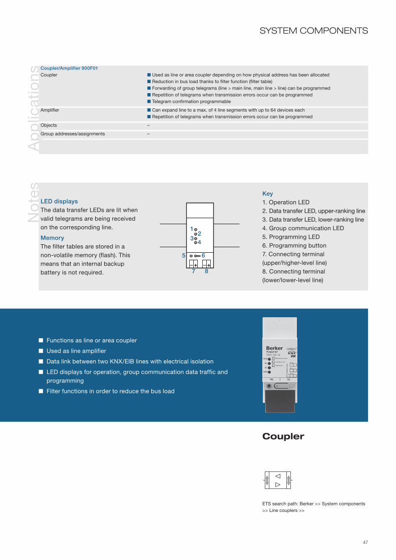
47
Functions as line or area coupler
Used as line amplifier
Data link between two KNX/EIB lines with electrical isolation
LED displays for operation, group communication data traffic and programming
Filter functions in order to reduce the bus load
Coupler
SYSTEM COMPONENTS
ETS search path: Berker >> System components >> Line couplers >>
Ap
plic
atio
ns
Coupler/Amplifier 900F01Coupler Used as line or area coupler depending on how physical address has been allocated Reduction in bus load thanks to filter function (filter table) Forwarding of group telegrams (line > main line, main line > line) can be programmed Repetition of telegrams when transmission errors occur can be programmed Telegram confirmation programmable
Amplifier Can expand line to a max. of 4 line segments with up to 64 devices each Repetition of telegrams when transmission errors occur can be programmed
Objects –
Group addresses/assignments –
No
tes
LED displaysThe data transfer LEDs are lit when valid telegrams are being received on the corresponding line.
MemoryThe filter tables are stored in a non-volatile memory (flash). This means that an internal backup battery is not required.
Key1. Operation LED2. Data transfer LED, upper-ranking line3. Data transfer LED, lower-ranking line4. Group communication LED5. Programming LED 6. Programming button7. Connecting terminal (upper/higher-level line) 8. Connecting terminal (lower/lower-level line)
+–+–6
21
5
34
87
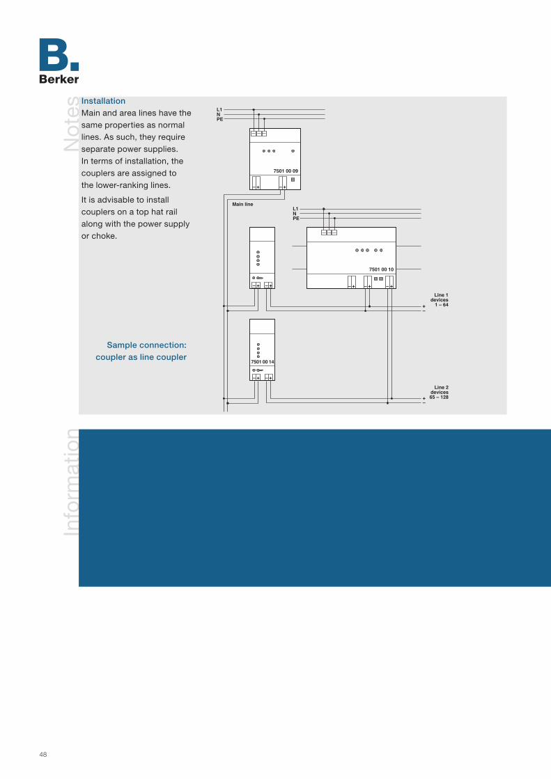
48
Info
rmat
ion
Not
esInstallationMain and area lines have the same properties as normal lines. As such, they require separate power supplies. In terms of installation, the couplers are assigned to the lower-ranking lines.
It is advisable to install couplers on a top hat rail along with the power supply or choke.
Sample connection: coupler as line coupler

49
SYSTEM COMPONENTS(Continued)
Coupler
No
tes Programming
The device can be programmed via the higher-ranking or lower-ranking line (physical address, parameters).
The device can also be commissi-oned from any line in the KNX/EIB installation. If this coupler is used, the physical address of the data interface used is no longer relevant.
Sample connection: coupler as line amplifier

50
Info
rmat
ion
Tech
nica
l dat
a
The IP router is designed as a rail mounted device. It connects KNX/EIB lines via data networks using the Internet Protocol (IP). This is done using the KNXnet/IP standard, which means that not only can KNX/EIB telegrams be forwarded between lines, but at the same time the bus can be accessed from a PC or other data processing devices (e.g. visualisations).
The use of the existing data network for communication spanning more than one line allows: - quick communication between KNX/EIB lines in the line/area coupler function- expansion of a KNX/EIB system to include more than one building through the use of LANs and WANs- direct forwarding of KNX/EIB data to each network user (not in bus monitor mode)- KNX/EIB remote configuration from each network access point.
The IP router is supplied via a separate 24 V AC/DC power supply, which means that a bus voltage failure can be reported via the network.
Supply Auxiliary voltage 24 V (12 – 30 V) AC/DC SELV Power consumption max. 800 mW at 30 V DC Current consumption max. 27 mA at 30 V DC Bus voltage 21 – 30 V DC SELV (via KNX/EIB bus line) Power consumption typ. 290 mW at 29 V DC Current consumption typ. 10 mA at 29 V DC
Network Ethernet connection 10BaseT (10 Mbit/s) Internet protocols ARP, ICMP, IGMP, UDP/IP, DHCP KNXnet/IP (KNX system specification) Core, Routing, Tunneling, Device Management
Behaviour in the event of voltage Bus voltage failure Internal saving and reporting failure/return via KNXnet/IP adjustable Bus voltage return Cancellation of the KNXnet/IP report
Operation and display element programming button Programming LED red Operation LED "Run" green Data reception LED bus "Line" yellow Connection LED IP network "LK" green IP reception LED "RX" yellow IP transmission LED "TX" red
Connections KNX/EIB Connecting terminal Auxiliary voltage supply Connecting terminal Ethernet network/LAN RJ45 jack
Protection class IP 20, EN 60 529 Safety class III
Ambient temperature range Operation -5 to +45 °C Storage/transport -25 to +70 °C
Mounting DIN rail 35 mm DIN EN 50 022
Dimensions (W x H x D) 36 x 90 x 60 mm 2 modules
Ord
er d
ata Device colour
Light grey ............... 7501 00 16 AccessoriesPower supply 24 V AC ................... 7591 00 01

51
Connection of KNX/EIB lines via fast data networks
Function as a line or area coupler
Bus access via data processing devices, e.g. for visualisation
LED status indication for operation, bus and IP reception, IP connection and IP transmission status
Connection of bus and auxiliary voltage via connecting terminals
IP router
SYSTEM COMPONENTS
ETS search path: Berker >> System Units >> IP Router >>
Ap
plic
atio
nsIP router 901001 Failure signal of the KNX/EIB system via KNXnet/IP to connected applications Freely selectable device name for easy recognition during configuration
Routing Filtering and forwarding of telegrams depending on the physical address and group address can be set for both communication directions (bus > IP, IP > bus)
IP configuration IP address assignment can be set to automatic (DHCP) or manual
Objects –
Group addresses /assignments –
Info
rmat
ion
IP
ATTENTION!The externally connected low vol-tage power supply is connected to the device with the potential of the LAN. Thus there is no more insula-tion to earth (no SELV!) if the LAN shield is earthed. Use external power supply only for the IP router, and do not connect any other additional devices. Do not use any ENX/EIN power supply as an external power supply if a bus line is connected to it!
Legend1. In example: power supply 24 V AC2. Output 24 V AC3. Connection 230 V AC4. Auxiliary voltage connection 24 V AC5. Bus connection6. IP transmission LED "TX"7. Data reception LED bus "Line"8. IP reception LED "RX"9. Connection LED IP network LED
"LK" 10. Operation LED "Run"11. Ethernet connection (RJ 45)12. Programming button13. Programming LED
L1NPE
EthernetTCP/IP Hub
Bus line 24 V AC
6
2
1
5 34
8910
12 1113
7

52
Info
rmat
ion
Ord
er d
ata Device colour
Light grey ................ 7502 00 01
Tech
nica
l dat
a
The bus coupling unit is executed as a top hat rail mounted device. It is the interface between the instabus KNX/EIB and the user modules in RMD module design.
Depending on the chosen application, output devices can be assigned to up to four channels.
This device can also be used as a logic controller with a wide variety of applications.
Supply via bus line 21–32 V DC
Controls and displays Programming button Programming LED Red
Connections Bus Pressure contact on data rail
Protection IP 20, EN 60529
Ambient temperature range Operation -5 to +45 °C Storage/transportation -25 to +70 °C
Mounting on top hat rail 35 mm, EN 50022
Dimensions (WxHxD) 17.5 x 90 x 58 mm 1 module

53
Interface between instabus KNX/EIB and user modules
Optionally four input or output channels
Use as logic controller possible
Bus coupling unit
SYSTEM COMPONENTS
ETS search path: Berker >> System components >> Bus coupling unit >>
Ap
plic
atio
ns
Switching LO, TF 201112 (only in conjunction with the switch actuator module) Operate relay depending on an ON or OFF telegram
Objects 4
Group addresses/assignments maximum of 8 each (common group address for multiple objects only at sending position)
No
tes
Key1. Programming LED2. Programming button
12
≥ 1&t

54
Info
rmat
ion
Ord
er d
ata
Tech
nica
l dat
a
The bus coupling unit is executed as a flush-mounted device, and makes the connection between the instabus KNX/EIB and the user module.
The user module may be a sensor or an actuator clipped onto the bus coupling unit. The KNX/EIB telegrams received from the line are evaluated and passed on as signals via the physical external interface (PEI) to the user module. In the opposite direction, signals from the user module are converted into KNX/EIB telegrams and sent onto the instabus.
By means of the programming button the physical address is transferred into the bus coupling unit.
Supply via bus line 21–32 V DC
Controls and displays Programming button Programming LED Red
Connections Bus Terminal User module 2 x 5-pin female connectors
Protection IP 20, EN 60529
Ambient temperature range Operation -5 to +45°C Storage/transportation -25 to +70 °C
Mounting Fitted in wall boxes dia. 58 mm Screw fixing Claw fixing not possible! Insertion depth 23 mm
Dimensions (WxHxD) 75 x 75 x 23 mm
Designwith support ring ..... 7504 00 01
AccessoriesProtective cover, grey .........................
7500 00 07

55
Bus coupling unit
SYSTEM COMPONENTS
ETS search path: Berker >> System components >> Bus coupling unit >>
Connection between instabus KNX/EIB and user modules
Integral physical external interface
LED to monitor programming
No
tes
Key1. Support ring2. Physical external interface (PEI)3. Programming button4. Programming LED
1
23
4

56
Info
rmat
ion
Ord
er d
ata
Tech
nica
l dat
a
The flush-mounted bus coupling unit plus is designed as a flush-mounted device, and makes the connection between the instabus KNX/EIB and the user module.
Examples of user modules are push-buttons or display devices on the bus coupling unit. The KNX/EIB telegrams received from the line are evaluated and passed on as signals via the physical external interface (PEI) to the user module. In the opposite direction, signals from the user module are converted into KNX/EIB telegrams and sent onto the instabus.
By means of the programming button, the physical address is transferred into the bus coupling unit.
Supply via bus line 21–32 V DC
Power consumption without user module max. 100 mW
Output power Physical external interface max. 150 mW
Controls and displays Programming button Programming LED red
Connections Bus Terminal User module 2 x 5-pin female connectors
Protection class IP 20, EN 60529
Ambient temperature range Operation - 5 to + 45 °C Storage/transport - 25 to + 70 °C
Assembly Installation in connector boxes Ø 58 mm Screw fastening Claw fixing not possible! Installation depth 23 mm
Dimensions (WxHxD) 71 x 71 x 23 mm
Designwith support ring ..... 7504 00 03
AccessoriesProtective cover, grey ..........................
7500 00 07

57
Bus coupling unit plus
SYSTEM COMPONENTS
Connection between instabus KNX/EIB and user modules
Supports user modules with higher power consumption
Integral physical external interface
LED to monitor programming
No
tes
Key1. Supporting ring2. Physical external interface3. Programming button4. Programming LED
1
23
4
IMPORTANT
Bus coupling unit for push-buttons with room thermostat and display 7566 x5 9x, Bluetooth gateway 7566 01 xx.
These devices have a higher current consumption and therefore require the flush-mounted bus coupling unit plus.

58
Info
rmat
ion
Ord
er d
ata
Tech
nica
l dat
a
The data interface is designed as a rail mounted device. It makes possible the coupling of a PC via the RS-232 serial interface for addressing, programming and diagnosis of KNX/EIB components.
The PC is connected to the data interface via a 9pole Sub-D connector.
Supply via bus line 21–32 V DC
Input PC interface serial, RS-232 - Transmission rate Typ. 9.6 kBaud - Voltage 5 –15 V SELV - Current input approx. 10 mA - Max. cable length, RS-232 15 m
Behaviour in the event of power Bus voltage failure Communication stopsfailure /restore Bus voltage restore Communication can be continued
Operation and display elements Programming button Programming LED red Operation LED (RUN) green Communication LED yellow
Connections Bus Terminal pins Inputs 9pole Sub-D socket
Protection class IP 20, EN 60529
Ambient temperature range Operation - 5 to +45°C Storage/transport - 25 to +70 °C
Mounting on top hat rail 35 mm, EN 50022
Mounting orientation as desired
Dimensions (WxHxD) 36 x 90 x 65 mm 2 modules
Device colourLight grey ................ 7501 00 13

59
Bus connection via connecting terminal
Display of the status via operation and communication LED
Push-on cover for reliable isolation of bus and mains voltage
Data interface
SYSTEM COMPONENTSN
ote
s
Key1. PC interface (RS-232 female) 2. Operation LED (RUN)3. Data communication LED (COM)
Beneath a cover:4. Programming button5. Programming LED6. Bus terminal pins7. Guide pins for cover
To connect a PC to the data inter-face, a 9pole RS-232 extension cable (wired up 1:1) must be used. If the PC has a 25pole RS-232 interface, then a suitable, fully wired-up adapter must be used.
The length of the connecting cable should not exceed 15 m !
EIB
RS 232
1
2
43
5 6
77

60
Info
rmat
ion
Tech
nica
l dat
a
The data interface is executed as a clip-on device in conjunction with a flush-mounted bus coupling unit. A 9-pin Sub-D connector permits connection of a PC to the instabus KNX/EIB.
This can be used for programming, parameter setting, addressing and diagnosis of the instabus devices.
To prevent interference, an automatic R-type switch is integrated into the data interface. The bus coupler‘s physical external interface type switches depending on whether a PC is connected or not. A green LED indicates that the device is ready for operation.
A frame, the bus coupling and a connection terminal are still needed to complete the device.
Supply via bus line 21–32 V DC
Inputs PC port serial, RS 232 – Transfer rate typ. 9.6 kBaud – Data level to DIN 66259, part 1 – Input level 6 V – Output level 3 V
Response to power Bus power failure only Communication abortsfailure/restore Only bus power restored Communication restored
Controls and displays Operation LED Green
Connections Bus coupling unit AST: 2 x 5-pin male connectors Inputs 9-pin Sub D female connector
Protection IP 20, to EN 60529
Ambient temperature range Operation -5 to +45°C Storage/transportation -25 to +70 °C
Mounting Clip onto bus coupling unit flush-mounted
Mounting orientation any
Dimensions (WxHxD) see dimensional drawings
Ord
er d
ata MODUL 2
White .......................
Polar white ..............
7506 00 12
7506 00 19
Berker S.1/B.1/B.3/ B.7 GLASWhite, glossy ...........
Polar white, glossy ..
Polar white, matt .....
Anthracite, matt .......
Aluminium, matt ......
7506 00 52
7506 00 59
7506 00 89
7506 00 85
7506 00 83
Berker K.1/K.5White .......................
Polar white ..............
Anthracite, matt .......
Aluminium, matt ......
Stainless steel, lacquered ................
7506 00 72
7506 00 79
7506 00 75
7506 00 74
7506 00 73
ARSYSWhite .......................
Polar white ..............
Light bronze, lacquered ................
Stainless steel, lacquered ................
7506 00 42
7506 00 49
7506 00 44
7506 00 43

61
Data interface
SYSTEM COMPONENTS
ETS search path: Berker >> Communication >> Serial >>
Operation LED
Connection of a PC for programming, parameter setting, etc.
Label strip
No
tes
Key1. Labelling field 2. Operation LED 3. PC port
1
23
EIB
RS 232

62
Info
rmat
ion
Ord
er d
ata
Tech
nica
l dat
a
The data interface is designed as a top hat rail mounted device. It allows a PC to be connected so that instabus KNX/EIB components can be addressed, programmed and diagnosed with the ETS 3 or ETS starter software.
The power is supplied completely by the USB interface from the connected PC. The device is programmed locally only by the connected PC with the physical address and therefore does not have a programming button or a programming LED.
The USB data interface firmware can be updated by PC and is therefore compatible with coming standards.
Supply via PC USB port
Transmission Transmission rate typ. 9.6 kBaud Protocol compatible with USB 1.1 and 2.0 Cable length max. 5 m
Connections Bus Terminal USB socket Type B
Protection class IP 20, EN 60529
Protection class II
Ambient temperature range Operation - 5 to + 45 °C Storage/transport - 25 to + 70 °C
Assembly on top hat rail 35 mm, EN 50022
Mounting orientation any
Dimensions (WxHxD) 36 x 90 x 63 mm 2 modules
Device colourLight grey ................ 7501 00 12
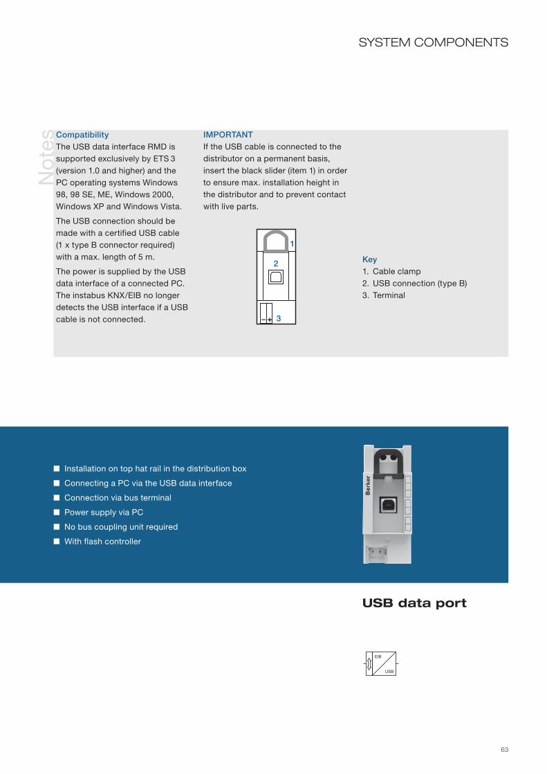
63
Installation on top hat rail in the distribution box
Connecting a PC via the USB data interface
Connection via bus terminal
Power supply via PC
No bus coupling unit required
With flash controller
USB data port
SYSTEM COMPONENTSN
ote
s
Key1. Cable clamp 2. USB connection (type B)3. Terminal
+–
1
2
3
EIB
USB
CompatibilityThe USB data interface RMD is supported exclusively by ETS 3 (version 1.0 and higher) and the PC operating systems Windows 98, 98 SE, ME, Windows 2000, Windows XP and Windows Vista.
The USB connection should be made with a certified USB cable (1 x type B connector required) with a max. length of 5 m.
The power is supplied by the USB data interface of a connected PC. The instabus KNX/EIB no longer detects the USB interface if a USB cable is not connected.
IMPORTANTIf the USB cable is connected to the distributor on a permanent basis, insert the black slider (item 1) in order to ensure max. installation height in the distributor and to prevent contact with live parts.

64
Info
rmat
ion
Tech
nica
l dat
a
The data interface allows a PC to be connected so that instabus KNX/EIB components can be addressed, programmed and diagnosed with the ETS 3 or ETS starter software.
The power is supplied completely by the flush-mounted USB interface from the connected PC. The device is programmed locally only by the connected PC with the physical address and therefore does not have a programming button or a programming LED.
The flush-mounted USB data interface firmware can be updated by PC and is therefore compatible with coming standards.
Supply via PC USB port
Transmission Transmission rate typ. 9.6 kBaud Protocol compatible with USB 1.1 and 2.0 Cable length max. 5 m
Connections Bus Terminal USB socket Type B
Protection class IP 20, EN 60529
Protection class II
Ambient temperature range Operation - 5 to + 45 °C Storage/transport - 25 to + 70 °C
Assembly Installation in connector boxes Ø 58 mm Screw fastening Claw fixing not possible! Installation depth 34 mm
Mounting orientation any
Dimensions (WxHxD) 71 x 71 x 34 mm
Ord
er d
ata Device colour
Light grey ................ 7504 00 04MODUL 2Centre plate- White .....................
- Polar white ............
For TDO boxes in Austria: * = (68)
(68)1033 02
(68)1033 09
Berker S.1/B.1/B.3/ B.7 GLASCentre plate- White, glossy .........
- Polar white, glossy
- Polar white, matt ...
- Anthracite, matt ....
- Aluminium, matt ....
*1033 89 12
*1033 89 19
*1033 19 09*1033 19 19
*1033 16 06
*1033 14 04
Berker K.1/K.5Centre plate- White .....................
- Polar white ............
- Stainless steel .......
*1035 70 02
*1035 70 09
*1035 70 04

65
Flush-mounted device for installation in a switch box
Connecting a PC via the USB data interface
Connection via bus terminal
Power supply via PC
No bus coupling unit required
With flash controller
USB data port
SYSTEM COMPONENTSN
ote
s
ARSYSCentre plate- White .....................
- Polar white ............- Light bronze, metal - Stainless steel .......
Centre plate with labelling field- White .....................
- Polar white ............
*1035 01 02
*1035 01 69*1034 00 01*1034 00 04
*1035 00 02
*1035 00 69
1
EIB
USB
CompatibilityThe USB data interface RMD is supported exclusively by the ETS 3 (version 1.0 and higher) and the PC operating systems Windows 98, 98 SE, ME, Windows 2000, Windows XP and Windows Vista.
The USB connection should be made with a certified USB cable (1 x type B connector required) with a max. length of 5 m.
The power is supplied by the USB data interface of a connected PC. The instabus KNX/EIB no longer detects the USB interface if a USB cable is not connected.
CoversCentre plates or central plates and intermediate ring for TAE/TDO phone systems are used as a cover (see order data below).
Key1. USB connection (type B)

66
Info
rmat
ion
Tech
nica
l dat
a
The data rail creates a connection between the devices via the pressure contacts of the KNX/EIB rail mounted devices. They are bonded into the top hat rail.
The inner pair of the four contact paths carries the bus voltage, and the outer pair the supply voltage. At the end of the data rail is a 4pole bus terminal that is used to establish the connection to the data rail.
The data rail cover protects the data rails against dirt and interference voltage. It is divisible into a 0.5 modules.
The terminal connects the components to the bus (with polarity reversal protection), and serves as a tapping block. There are connection facilities for a maximum of 2 x 4 conductors.
Data rail with connectorProtection class IP 20, EN 60529
Ambient temperature range Operation - 5 to +45 °C Storage/transport - 25 to +70 °C
Mounting on top hat rail 35 mm, EN 50022 bonded-in
Mounting orientation as desired
Dimensions (WxHxD) 214 x 24 x 1.8 mm (for top hat rail 35 x 7.5 mm) 12 modules
Data rail coverProtection IP 20, EN 60529
Ambient temperature range Operation -5 to +45 °C Storage/transportation -25 to +70 °C
Mounting on top hat rail 35 mm, EN 50022 Snap-on
Mounting orientation any
Dimensions (W) 240 mm 13.5 modules
TerminalConnections Bus 2 x 4 clip-on terminals 0.6–0.8 mm Coding Red/black = +/–
Protection IP 20, EN 60529
Ambient temperature range Operation -5 to 45 °C Storage/transportation -25 to 70 °C
Mounting Clip on to connector pins of bus devices
Mounting orientation any
Dimensions (WxHxD) 11.5 x 10 x 10.2 mm
Ord
er d
ata Data rail with
connectorfor top hat rail 35 x 7.5 mm12 modules ............ 7500 00 08
Data rail coverLight grey ................ 7500 00 04
TerminalRed/black ................ 7500 00 05

67
Data rail with connector
Data rail cover
Terminal
SYSTEM COMPONENTS
ETS search path: Berker >> System accessory >>
No
tes
Key1. Data rail2. 24 V DC (yellow)3. KNX/EIB + (red)4. KNX/EIB – (black)5. 0 V (white)
The configuration of the strip con-ductors is only correct if the con-nector is to the right during instal-lation. The data rail must not be shortened. Empty areas of the top hat rail with a data rail inserted must be provided with a cover.
Connection to another lineThe outer connector terminals (yellow and white) of the data rail are used to connect the non-choked 30 V DC voltage, e. g. to supply KNX/EIB lines via a sepa-rate choke.
Data rail with connector
21
34
5
Data rail cover Terminal

68

69
SENSORS
Sensors are a key element of the instabus KNX/EIB. They convert physical variables into electrical values, process them and
send a telegram onto the bus as appropriate.
Push-buttons 72–195Physical sensors 196–221Binary inputs 222–237Time switches 238–247Analogue inputs 248–271Other 270–273
Dim
. dra
win
gs
Glo
ssar
yTr
aini
ng
Ser
vice
Oth
erco
mp
one
nts
Lo
gic
mo
dul
esV
isu
al r
epre
-se
ntat
ion
sS
enso
rsA
ctu
ato
rs

70
Info
rmat
ion
Ord
er d
ata
Tech
nica
l dat
a
The push-button BCU 1gang is executed as a flush-mounted device. It consists of a bus coupling unit, a micro push-button with associated evaluation electronics and a status LED, as well as a mechanical mounting unit for rockers.
The rockers are not included. They can be ordered separately in differing designs according to the application (1gang, with lens, with labelling).
Supply via bus line 21–32 V DC
Controls and displays Button with rocker mounting Programming button Programming LED Red Status LED Red
Connections KNX/EIB Terminal
Protection IP 20, EN 60529
Ambient temperature range Operation -5 to +45 °C Storage/transportation -25 to +70 °C
Mounting Fitting in wall boxes ∅ 60 mm, 40 mm deep ∅ 60 mm, 60 mm deep
Mounting orientation any
Dimensions (WxHxD) 71 x 71 x 32 mm
Design- with support ring ...
Rocker MODUL 2 White .......................- with lens ................- with labelling .........
Polar white ..............- with lens ................- with labelling .........
7514 10 00
1620 021621 121626 02
1620 091621 191626 09
Rocker Berker S.1/B.1/B.3/B.7 GLASWhite, glossy ...........- with lens ................- with labelling .........
Polar white, glossy- with lens ................- with labelling .........
Polar white, matt .....- with lens ................- with labelling .........
Rocker Berker S.1/B.1/B.3/B.7 GLASAnthracite, matt .......- with lens ................- with labelling .........
Aluminium, matt ......- with lens ................- with labelling .........
Rocker Berker K.1/K.5White .......................- with lens ................- with labelling .........
Polar white ..............- with lens ................- with labelling .........
Anthracite, matt .......- with lens ................- with labelling .........
Aluminium, matt ......- with lens ................- with labelling .........
1405 70 021415 70 021426 70 02
1405 70 091415 70 091426 70 09
1405 70 061415 70 061426 70 06
1405 70 241415 70 241426 70 24
1620 16 061621 16 061626 16 06
1620 14 041621 14 041626 14 04
1620 89 821621 89 821626 89 82
1620 89 891621 89 891626 89 89
1620 19 091621 19 091626 19 09

71
Status LED to indicate operating states or as orientation light
Switching of a function group
SENSORSA
pp
licat
ions
Switching 105501 Switching functions: ON or OFF or TOGGLE LED as status indicator, continuous ON or continuous OFF
Objects 1
Group addresses/assignments maximum of 3 each
ETS search path: Berker >> Push-button >> Push-button 1gang >>
Push-button BCU 1gang
Rocker Berker K.1/K.5Stainless steel .........- with lens ................- with labelling .........
1405 70 041415 70 041426 70 04
Rocker Berker ARSYSWhite .......................- with lens ................- with labelling .........
Polar white ..............- with lens ................- with labelling .........
Light bronze, metal ...- with lens ................- with labelling .........
Stainless steel .........- with lens ................- with labelling .........
1405 00 021415 00 021426 00 02
1405 00 691415 00 691426 00 69
1404 00 011416 00 011436 00 01
1404 00 041416 00 041436 00 04
RockerShatter-proof IP 44White- with lens ................- with labelling .........
Polar white- with lens ................- with labelling .........
155015531629
1550 091553 091629 09
Ro
cker
s
Rocker Rocker with lens Rocker with labelling
1

72
Info
rmat
ion
Tech
nica
l dat
a
The push-button BCU 2gang is executed as a flush-mounted device. It consists of a bus coupling unit, two micro push-buttons with associated evaluation electronics and two status LEDs, as well as a mechanical mounting unit for rockers.
The rockers are not included. They can be ordered separately in differing designs according to the application (2gang, with lens, with arrow symbol).
Supply via bus line 21–32 V DC
Controls and displays Button left Button right Programming button Programming LED Red 2 status LEDs Red
Connections KNX/EIB Terminal
Protection IP 20, EN 60529
Ambient temperature range Operation -5 to +45 °C Storage/transportation -25 to +70 °C
Mounting Fitting in wall boxes ∅ 60 mm, 40 mm deep ∅ 60 mm, 60 mm deep
Mounting orientation any
Dimensions (WxHxD) 71 x 71 x 32 mm
Ord
er d
ata Design
- with support ring ...
Rockers MODUL 2 White .......................- with lens ................- with labelling .........
Polar white ..............- with lens ................- with labelling .........
Rockers Berker S.1/B.1/B.3/B.7 GLASWhite, glossy ...........- with lens ................- with labelling .........
Polar white, glossy- with lens ................- with labelling .........
Polar white, matt .....- with lens ................- with labelling .........
Rockers Berker S.1/B.1/B.3/B.7 GLASAnthracite, matt .......- with lens ................- with labelling .........
Aluminium, matt ......- with lens ................- with labelling .........
Rockers Berker K.1/K.5White .......................- with lens ................- with arrow symbol ..
Polar white ..............- with lens ................- with arrow symbol ..
Anthracite, matt .......- with lens ................- with labelling .........
7514 20 00
1623 021627 021625 02
1623 091627 091625 09
1435 70 021437 70 021435 71 02
1435 70 091437 70 091435 71 09
1435 70 061437 70 061435 71 06
1623 16 061627 16 061625 16 06
1623 14 041627 14 041625 14 04
1623 89 821627 89 821625 89 82
1623 89 891627 89 891625 89 89
1623 19 091627 19 091625 19 09

73
Two status LEDs to indicate operating states or as orientation light
Dimmer/shutter control for one function group
Switch up to two function groups
SENSORSA
pp
licat
ions
Switching, dimming, shutter 105701 Switching or dimming or shutter control Switching function with toggle operation Status LED with dedicated communication objects Area dimming
Objects 4
Group addresses/assignments maximum 4/maximum 5
ETS search path: Berker >> Push-button >> Push-button 2gang >>
Push-button BCU 2gang
Rockers Berker K.1/K.5Aluminium, matt ......- with lens ................- with labelling .........
Stainless steel .........- with arrow symbol ..
Rockers Berker ARSYSWhite .......................- with lens ................- with arrow symbol ..
Polar white ..............- with lens ................- with arrow symbol ..
Light bronze, metal ...- with arrow symbol ..
Stainless steel .........- with arrow symbol ..
RockersShatter-proof IP 44White .......................- with arrow symbol ..
Polar white ..............- with arrow symbol ..
1435 70 241437 70 241435 71 24
1435 70 041435 71 04
1435 00 021437 00 021435 01 02
1435 00 691437 00 691435 01 69
1434 00 011434 01 01
1434 00 041434 01 04
15521552 22
1552 091552 29
2
Ro
cker
s
Rockers Rockers with red lenses Rockers with arrow symbol

74
Info
rmat
ion
Ord
er d
ata
Tech
nica
l dat
a
The group push-button BCU 1gang is executed as a flush-mounted device. It consists of a bus coupling unit, two micro push-buttons with associated evaluation electronics and a status LED, as well as a mechanical mounting unit in the neutral mid position for rockers.
The rockers are not included. They can be ordered separately in differing designs according to the application (1gang, with lens, with symbol).
Supply via bus line 21–32 V DC
Controls and displays Upper button Lower button Programming button Programming LED Red Status LED Red
Connections KNX/EIB Terminal
Protection IP 20, EN 60529
Ambient temperature range Operation -5 to +45 °C Storage/transportation -25 to +70 °C
Mounting Fitting in wall boxes ∅ 60 mm, 40 mm deep ∅ 60 mm, 60 mm deep
Mounting orientation any
Dimensions (WxHxD) 71 x 71 x 32 mm
Design- with support ring ...
Rocker MODUL 2 White .......................- with lens ................- with symbol ...........
Polar white ..............- with lens ................- with symbol ...........
7514 11 00
1620 021621 121620 22
1620 091621 191620 29
Rocker Berker S.1/B.1/B.3/B.7 GLASWhite, glossy ...........- with lens ................- with symbol ...........
Polar white, glossy- with lens ................- with symbol ...........
Polar white, matt .....- with lens ................- with symbol ...........
Rocker Berker S.1/B.1/B.3/B.7 GLASAnthracite, matt .......- with lens ................- with symbol ...........
Aluminium, matt ......- with lens ................- with symbol ...........
Rocker Berker K.1/K.5White .......................- with lens ................- with symbol ...........
Polar white ..............- with lens ................- with symbol ...........
Anthracite, matt .......- with lens ................- with symbol ...........
1405 70 021415 70 021405 71 02
1405 70 091415 70 091405 71 09
1405 70 061415 70 061405 71 06
1620 16 061621 16 061620 16 16
1620 14 041621 14 041620 14 14
1620 89 821621 89 821620 89 12
1620 89 891621 89 891620 89 19
1620 19 091621 19 091620 19 19

75
Status LED to indicate operating states or as orientation light
Dimmer/shutter control for one function group
Switch up to two function groups
SENSORSA
pp
licat
ions
Switching, dimming, shutter 105601 Switching or dimming or shutter control Up to two switching options by toggle function
Objects 3
Group addresses/assignments maximum of 4 each
ETS search path: Berker >> Push-button >> Push-button 1gang >>
Group push-button BCU 1gang
Rocker Berker K.1/K.5Aluminium, matt ......- with lens ................- with symbol ...........
Stainless steel .........- with lens ................- with symbol ...........
1405 70 241415 70 241405 71 24
1405 70 041415 70 041405 71 04
Rocker Berker ARSYSWhite .......................- with lens ................- with symbol ...........
Polar white ..............- with lens ................- with symbol ...........
Light bronze, metal ...- with lens ................- with symbol ...........
Stainless steel .........- with lens ................
1405 00 021415 00 021405 03 02
1405 00 691415 00 691405 03 69
1404 00 011416 00 011404 03 01
1404 00 041416 00 041404 03 04
RockerShatter-proof IP 44White- with lens ................
Polar white- with lens ................
15501553
1550 091553 09
1
Ro
cker
s
Rocker Rocker with lens Rocker with symbol

76
Info
rmat
ion
Tech
nica
l dat
a
The group push-button BCU 2gang is executed as a flush-mounted device. It consists of a bus coupling unit, four micro push-buttons with associated evaluation electronics and two status LEDs, as well as a mechanical mounting unit in the neutral mid position for rockers.
The rockers are not included. They can be ordered separately in differing designs according to the application (2gang, with lens, with symbol, with arrow symbol).
Supply via bus line 21–32 V DC
Controls and displays 2 buttons left (upper and lower) 2 buttons right (upper and lower) 2 status LEDs Red
Connections KNX/EIB Terminal
Protection IP 20, to EN 60529
Ambient temperature range Operation -5 to +45 °C Storage/transportation -25 to +70 °C
Mounting Fitting in wall boxes ∅ 60 mm, 40 mm deep ∅ 60 mm, 60 mm deep
Mounting orientation any
Dimensions (WxHxD) 71 x 71 x 32 mm
Ord
er d
ata Design
- with support ring ...
Rockers MODUL 2 White .......................- with symbol ...........- with arrow symbol ..
Polar white ..............- with symbol ...........- with arrow symbol ..
7514 21 00
1623 021644 021625 02
1623 091644 091625 09
Rockers Berker S.1/B.1/B.3/B.7 GLASWhite, glossy ...........- with symbol ...........- with arrow symbol ..
Polar white, glossy ..- with symbol ...........- with arrow symbol ..
Polar white, matt .....- with symbol ...........- with arrow symbol ..
1623 89 821644 89 821625 89 82
1623 89 891644 89 891625 89 89
1623 19 091644 19 091625 19 09
Rockers Berker S.1/B.1/B.3/B.7 GLASAnthracite, matt .......- with symbol ...........- with arrow symbol ..
Aluminium, matt ......- with symbol ...........- with arrow symbol ..
1623 16 061644 16 061625 16 06
1623 14 041644 14 041625 14 04
Rockers Berker K.1/K.5White .......................- with symbol ...........- with arrow symbol ..
Polar white ..............- with symbol ...........- with arrow symbol ..
Anthracite, matt .......- with symbol ...........- with arrow symbol ..
1435 70 021435 72 021435 71 02
1435 70 091435 72 091435 71 09
1435 70 021435 72 021435 71 02

77
Two status LEDs to indicate operating states or as orientation light
Dimmer/shutter control for two function groups
Switch up to four function groups
SENSORSA
pp
licat
ions
Switching, dimming, shutter 105801 Switch and dimmer or Switch and shutter control or Dimmer and shutter control Maximum of 4 switching options by toggle function
Objects 8
Group addresses/assignments maximum of 8 each
ETS search path: Berker >> Push-button >> Push-button 2gang >>
Group push-button BCU 2gang
2
Ro
cker
s
Rockers Rockers with symbol Rockers with arrow symbol
Rockers Berker K.1/K.5Aluminium, matt ......- with symbol ...........- with arrow symbol ..
Stainless steel .........- with symbol ...........- with arrow symbol ..
1435 70 241435 72 241435 71 24
1435 70 041435 72 041435 71 04
Rockers Berker ARSYSWhite .......................- with symbol ...........- with arrow symbol ..
Polar white ..............- with symbol ...........- with arrow symbol ..
Light bronze, metal ...- with symbol ...........- with arrow symbol ..
Stainless steel .........- with symbol ...........- with arrow symbol ..
1435 00 021435 03 021435 01 02
1435 00 691435 03 691435 01 69
1434 00 011434 03 011434 01 01
1434 00 041434 03 041434 01 04
RockersShatter-proof IP 44White .......................- with arrow symbol ..
Polar white ..............- with arrow symbol ..
15521552 22
1552 091552 29

78
Info
rmat
ion
Tech
nica
l dat
a
The push-button 1gang is a user module for clipping onto the flush-mounted bus coupling unit. It is supplied with or without labelling field (separate order number).
In the variant without labelling field the LEDs are not visible.
The device is completed by a cover frame, the bus coupling unit and a terminal.
Supply via bus line 21–32 V DC
Operation and Upper buttondisplay elements Lower button Operation LED Green Status LED Red
Connections Bus coupling unit, flush-mounted PEI: 2 x 5-pin male connectors
Protection IP 20, EN 60529
Ambient temperature range Operation -5 to +45 °C Storage/transportation -25 to +70 °C
Mounting Clip onto bus coupling unit, flush-mounted
Mounting orientation any
Dimensions (WxHxD) see dimensional drawings
Ord
er d
ata MODUL 2
White ........................- with labelling ..........
Polar white ...............- with labelling ..........
7516 11 127516 10 12
7516 11 197516 10 19
Berker S.1/B.1/B.3/ B.7 GLASPolar white, matt .....- with labelling ..........
Anthracite, matt .......- with labelling ..........
Aluminium, matt ......- with labelling ..........
7516 11 897516 10 89
7516 11 857516 10 85
7516 11 837516 10 83
Berker ARSYSWhite .......................- with labelling ..........
Polar white...............- with labelling ..........
Light bronze, lacquered .................- with labelling ..........
Stainless steel, lacquered .................- with labelling ..........
7516 11 427516 10 42
7516 11 497516 10 49
7516 11 447516 10 44
7516 11 437516 10 43

79
Operation of switch, dim or shutter actuators
Value transmitter for brightness values
Operation LED
Status LED to indicate object states
Light scene extension
Integral mechanical anti-dismantling protection
SENSORSA
pp
licat
ions
Dimming 100C12 Status LED programmable Operation LED programmable Switch/dimmer function Area dimming programmable
Objects 2
Group addresses/assignments maximum of 10 each
Shutter 100D12 Step and move operation Operation LED programmable Number of step commands for variable jog mode
Objects 2
Group addresses/assignments maximum of 10 each
Switching 100912 LED for transmission monitoring in time function Operation LED programmable Switching commands customizable
Objects 1
Group addresses/assignments maximum of 10 each
Value transmitter 101B01 Two values to be sent to dim and/or analogue actuators and/or control units Passive or active extension of a light scene push-button
Objects 1
Group addresses/assignments maximum of 1 each
Switching/pushing 103301 Status LED with separate object Operation LED programmable Switching commands customizable Toggle function for up to two group commands
Objects 3
Group addresses/assignments maximum of 13 each
ETS search path: Berker >> Push-button >> Push-button 1gang >>
Push-button 1gangAccessoriesLabelling fieldwith cover plate
MODUL 2White .......................Polar white...............
Berker S.1/B.1/B.3/ B.7 GLASPolar white...............Aluminium ................Anthracite ................
7596 00 017596 00 02
7596 00 077596 00 097596 00 08
Berker ARSYSWhite .......................Polar white...............Light bronze, lacquered ................Stainless steel, lacquered .................
7596 00 037596 00 06
7596 00 05
7596 00 041
with labelling

80
Info
rmat
ion
Tech
nica
l dat
aO
rder
dat
a
The push-button 1gang is a user module for mounting on a flush-mounted bus coupling unit.
When pressed, the push-button sends telegrams to the instabus KNX/EIB; these trigger the functions corresponding to the application that is loaded. The new push-button generation is designed without a central web, which means that large rockers are available for convenient operation. The push-button distinguishes between actuation of the right-hand and left-hand sides of the rocker (2 buttons).
The cover is removable, the entire surface of the rocker is available for inserting a labelling plate. By arranging the operation LED at the lower edge and the status LEDs on the side edges of the rocker, the entire rocker surface is kept open for labelling.
The austere, minimalistic form is superbly suited to the series' form language.
Supply via bus line 21–32 V DC
Operation and display elements Left-hand button Part of the rocker Right-hand button Part of the rocker Operation LED White 2 status LEDs at side Red
Connections Bus coupling unit flush-mounted AST: 2 x 5pole pin contact strip
Protection IP 20, EN 60529
Ambient temperature range Operation -5 to +45 °C Storage/transport -25 to +70 °C
Installation Clip on bus coupling unit flush-mounted
Mounting orientation as desired
Dimensions (WxHxD) see dimensional drawings
Berker S.1/B.1/B.3/B.7 GLASfor White and Polar white.........................
for Anthracite and Aluminium ................
7516 13 80
7516 13 85
Berker K.1/K.5for White and Polar white.........................
Anthracite ................
Aluminium ................
Stainless steel ..........
7516 13 70
7516 13 75
7516 13 74
7516 13 73

81
SENSORS
1
Activation of switch, dimmer or shutter actuators
Value transmitter for transmitting brightness values
Operation LED
Status LED for indicating switching states, etc.
Light scene extension unit
Integrated anti-dismantling protection
Ap
plic
atio
ns
Dimming 100C03 Status LED adjustable Operation LED adjustable Switching/dimmer function Area dimming adjustable
Objects 2
Group addresses/assignments maximum 10 each
Shutter 100D03 Step and move command Operation LED adjustable Number of step commands for variable jog mode
Objects 2
Group addresses/assignments maximum 10 each
Switching 100903 Operation LED adjustable Switching commands freely adjustable Status LED with time function for transmission monitoring
Objects 1
Group addresses/assignments maximum 10 each
Value transmitter 101B03 Two values for sending to dim and/or analogue actuators and/or control units Passive or active extension unit of a light scene push-button
Objects 1
Group addresses/assignments maximum 1 each
Switching/pushing 103303 Status LED with separate object Operation LED adjustable Switching commands freely adjustable Toggle function for up to two group commands
Objects 3
Group addresses/assignments maximum 13 each
ETS search path: Berker >> Push-button >> Push-button, 1gang >>
Push-button 1gang with labelling field

82
Info
rmat
ion
Ord
er d
ata
Tech
nica
l dat
a
The push-button 1gang standard is a user module for bolting to a flush-mounted bus coupling unit.
When pressed, the push-button sends telegrams to the instabus KNX/EIB. This then triggers functions depending on the application which has been loaded.
The B.IQ has no frames. This means that large rockers are available to ensure ease of operation. The push-button distinguishes between activation of the right and left side of the rocker (button).
The operation LED is located in the centre while the status LEDs are located on the sides of the push-button. They can therefore light the optional labelling field, in addition to displaying switching statuses for example.
Supply via bus line 21–32 V DC
Operation and Button on left Part of the rockerdisplay elements Button on right Part of the rocker Operation LED Blue 2 lateral status LEDs White
Connections Bus coupling unit, flush-mounted PEI: 2 x 5-pin male connectors
Protection IP 20, EN 60529
Ambient temperature range Operation -5 to +45 °C Storage/transport -25 to +70 °C
Mounting Bolting to flush-mounted bus coupling unit
Mounting orientation any
Dimensions (WxHxD) see dimensions diagrams
BERKER B.IQ Polar white ..............
Stainless steel .........
Glass, polar white....
7516 10 99
7516 10 93
7516 10 91
AccessoriesLabelling fieldclear transparent ..... 7590 00 80

83
Operation of switch, dim or shutter actuators
Value transmitter for brightness values
Operation LED
Status LED for displaying switching statuses
Light scene extension
Integral mechanical anti-dismantling protection
SENSORSA
pp
licat
ions
Dimming 100C03 Status LED programmable Operation LED programmable Switch/dimmer function Area dimming programmable
Objects 2
Group addresses/assignments maximum 10 each
Shutter 100D03 Step and move operation Operation LED programmable Number of step commands for variable jog mode
Objects 2
Group addresses/assignments maximum 10 each
Switching 100903 Operation LED programmable Switching commands programmable Status LED with time function for transmission monitoring
Objects 1
Group addresses/assignments maximum 10 each
Value transmitter 101B03 Two values to be sent to dimming and/or analogue actuators and/or control units Passive or active extension of a light scene push-button
Objects 1
Group addresses/assignments maximum 1 each
Switching/pushing 103303 Status LED with separate object Operation LED programmable Switching commands programmable Toggle function for up to two group commands
Objects 3
Group addresses/assignments maximum 13 each
ETS search paths: Berker >> Push-button >> 1gang push-button >> Berker >> Push-button >> B.IQ >>
B.IQ push-button 1gang standard
1

84
Info
rmat
ion
Ord
er d
ata
Tech
nica
l dat
a
The push-button 1gang is designed as a monoblock, i.e. with integrated bus coupling unit. The device can be connected directly to the bus line for commissioning.
When pressed, the push-button sends telegrams to the instabus KNX/EIB. The application allows selection of the function. It is no longer necessary to load a separate application for the corresponding function.
The new push-button generation is designed without a central web, which means that large rockers are availa-ble for convenient operation. The push-button distinguishes between actuation of the right-hand and left-hand sides of the rocker (2 buttons). The cover is removable, the entire surface of the rocker is available for inserting a labelling plate.
Supply via bus line 21 – 32 V DC Power consumption KNX/EIB typ. 150 mW
Operation and display elements Left push-button Part of the rocker Right push-button Part of the rocker Operation LED white 2 status-LEDs orange
Connections KNX/EIB Connection terminal
Protection class IP 20, EN 60 529 Safety class III
Ambient temperature range Operation -5 to +45 °C Storage/transport -25 to +70 °C
Mounting Built into flush-mounted box Ø 60 mm
Dimensions Installation depth approx. 23 mm Assembling height from wall approx. 13 mm
BERKER Q.1Polar white, velvety ... 7514 12 29
AccessoriesLabelling fieldsheets ...................... 9498 29 01

85
Activation of switch, dimmer or shutter actuators
Value transmitter 1-byte, e.g. for transmitting brightness values
Light scene extension unit
Operation LED
Status LEDs for indicating switching states, etc.
Integrated anti-dismantling protection
SENSORSA
pp
licat
ions
Standard 1gang 10C901 Function of the operation LED and the status LEDs adjustableStandard 1gang 10C911 (for ETS 3 from version d) Function of the device adjustable: switching, dimming, shutter, value transmitter or scene extension unit
Switching Rockers or push-button function adjustable Command when buttons are pressed adjustable (ON, OFF, TOGGLE)
Dimming Command when pressing the left/right rocker adjustable (brighter, ON/darker, OFF) Time between switching and dimming adjustable
Shutter Command when pressing the left/right rocker adjustable (UP, DOWN) Time between short and long-time command adjustable
Value transmitter Value when the rocker is pressed adjustable per page (0 to 255 / 0 to 100 %)
Scene extension unit Scene number when rocker is pressed adjustable per page Mode of operation with/without memory function adjustable
Objects 2
Group addresses/assignments maximum 100 each
ETS search paths: Berker >> push-button >> push-button, 1gang >>
Push-button 1gang with labelling field and bus coupling unit
1

86
Info
rmat
ion
Ord
er d
ata
Tech
nica
l dat
a
The glass sensor is intended for flush-mounted installation in a 2gang wall box for glass sensor, and when connected to a universal interface performs the function of a push-button. The glass sensor does not have any mechanical operating elements. Actuation is detected via capacitive sensor surfaces, and the LEDs are applied directly to the back of the glass plate, making the surface completely flat. Yet the glass sensor still provides the usual convenient operation. Pairs of operating surfaces can be joined logically into rockers, the LEDs next to the sensor surfaces can be controlled individually to indicate the status.
The glass sensor can be labelled at the factory. To have this done, you can use the Web Configurator at www.berker.com/ts-sensor – this generates a unique order number. The imprint is made on the rear, and is thus protected against dirt, wear and damage.
Supply Operating voltage 8 – 30 V DC via separate power supply Power consumption 20 mA
Loading capacity Switching voltage max. 30 V DC Switching current (adapter 7590 00 32) max. 10 mA LED input voltage max. 5 V DC LED input current max. 1 mA
Operation and display elements 1 x 2 sensor surfaces left/right Operation LED blue 2 status LEDs white 2 jumpers on rear Setting functions of the LEDs
Connections Ribbon cable for adapter connection 26pole plug
Protection class IP 21, EN 60 529 Safe for moist cleaning
Ambient temperature range Operation -5 to +45 °C Storage/transport -25 to +70 °C
Installation Snap onto wall box (order no. 1870) Adapter ring for anti-dismantling protection optional
Dimensions Glass plate 160 x 86 x 4 mm Assembling height from wall 4.7 mm (seated on wall) 10.7 mm (with adapter ring) Surface compensation max. 20 mm
BERKER TS SensorGlass, polar white....
Glass, black.............
Glass, aluminium .....
with configured labelling ...................
1681 09
1681 05
1681 07
1691 0x ...
AccessoriesWall box 2gang for glass sensor ...........
Adapter for KNX/EIB and relay ..................
Universal interface 2gang comfort .........
Universal interface 4gang comfort .........
1870
7590 00 32
7564 20 01
7564 40 01

87
8 to 30 V DC
7590 00 32
7564 40 01
7564 20 01IN
LED
INLE
D
Flat surface with capacitive sensor surfaces
White status LED for indicating switching states, etc.
Blue operation LED
Operating mode of LED adjustable via jumper
Bus connection via universal interfaces
Optional anti-dismantling protection via adapter ring
Optional customer-specific labelling
Glass sensor, 1gang
Info
rmat
ion Connection
The glass sensor is connected to the adapter for KNX/EIB and relay or via the KNX/EIB adapter 2 x 8gang using a supplied ribbon cable. The adapter that is used is connected with the KNX/EIB via push-button interfaces.The glass sensor requires a sepa-rate supply voltage. This is likewise connected to the adapter being used.
MountingMounting is performed by snap-ping the glass sensor onto the wall box 2gang for glass sensor. Adap-ters and push-button interfaces can be housed conveniently in the wall box. The wall box must be taken into account in the planning!
LED functionIn the state at delivery the LEDs of the glass sensor have fixed func-tions assigned to them. If the LEDs are to be controlled via KNX/EIB,
jumpers on the rear of the glass sen-sor have to be adjusted. A separate universal interface 2gang comfort must be provided for activation of the blue operation LED.
Legend1. Glass sensor2. Status LEDs
3. Operation LED4. Supply voltage5. Universal interface for connec-
ting the operation LED6. Universal interface for connec-
ting the sensor surfaces with the status LEDs
7. Adapter for KNX/EIB and relay8. Ribbon cable connection
Connection overview for glass sensor 1gang with external activation of the operation and status LEDs
SENSORS
5
22
1
6
34
8
7

88
Info
rmat
ion
Tech
nica
l dat
a
The adapter for KNX/EIB and relay is intended for installation in a flush-mounted switch box, and establishes the connection between a glass sensor and interfaces of the building management systems.
8 channels are available for signal transmission and for activation of the status LEDs. Signal transmission is via optocouplers.
The adapter has separate screw terminals for connecting inputs, for activating the status LEDs of the glass sensor, for activating the operation LED, and for connecting the external power supply of the sensor.
Supply Operating voltage 8 – 30 V DC via separate power supply
Loading capacity Switching voltage max. 30 V DC Switching current max. 10 mA LED input voltage max. 5 V DC LED input current max. 1 mA
Connections Universal interfaces Screw terminals: 0.14 – 0.5 mm² Operation LED/voltage supply Screw terminals: max. 1 mm² Glass sensor (168x 0x) 26pole plug
Ambient temperature range Operation -5 to +45 °C Storage/transport -25 to +70 °C
Mounting in wall box (order no. 1870)
Dimensions (W x H ) 46 x 51 mm
Ord
er d
ata Device colour
Green ..................... 7590 00 32

89
8 to 30 V DC
7590 00 32
7564 40 01 7564 20 01
INLE
D
INLE
D
Connection of the interfaces via screw terminals
Screw terminals separated according to functions
SENSORS
Adapter for KNX/EIB and relay
Info
rmat
ion Connection
The adapter is connected to the glass sensor using the ribbon ca-ble supplied with the sensor. The interfaces to the KNX/EIB are con-nected via screw terminals. Signal transmission is via optocouplers. Therefore during connection atten-tion must be paid to the potentials. In each case the conductor with the higher potential must be con-nected to the + terminal of the numbered terminal space.
Legend1. Supply voltage connection2. Operation LED connection3. Inputs connections4. Status LEDs connection5. Glass sensor connection
Connection example, adapter and interfaces for the glass sensor 1gang
5
2 1
3
4

90
Info
rmat
ion
Tech
nica
l dat
a
The push-button 1gang comfort is a user module for clipping onto the flush-mounted bus coupling unit. The device is completed by a cover frame, the bus coupling unit and a terminal.
Operation of switch, dim or shutter actuators
Value transmitter for brightness and/or temperature values or as a light scene extension
Control of up to 2 dimmer groups via the “one push-button” dimming operation
Open value input, 1-byte and 2-byte floating point
Control of forced guidance (EIS 8)
Supply via bus line 21–32 V DC
Operation and display elements Upper button Lower button Operation LED Green 2 status LEDs Red
Connections Bus coupling unit, flush-mounted PEI: 2 x 5-pin male connectors
Protection IP 20, EN 60529
Ambient temperature range Operation -5 to +45 °C Storage/transportation -25 to +70 °C
Mounting Clip onto bus coupling unit, flush-mounted
Mounting orientation any
Dimensions (WxHxD) see dimensional drawings
Ord
er d
ata MODUL 2
White .......................
Polar white ..............
7516 16 12
7516 16 19
Berker S.1/B.1/B.3/B.7 GLASPolar white, matt .....
Anthracite, matt .......
Aluminium, matt ......
7516 16 89
7516 16 85
7516 16 83
Berker ARSYSWhite .......................
Polar white ..............
Light bronze,lacquered ................
Stainless steel,lacquered ................
7516 16 42
7516 16 49
7516 16 44
7516 16 43

91
Assignment of one status LED to each of the two push-buttons
LED setup options: permanently ON/OFF, status indication, inverted status indication, operating indication, flash mode
Free project design for each push-button
Operation on two switchable user levels
Cyclic telegram repetition
Push-button lockable
Alarm function in case of separation of push-button from bus coupling unit
Integral mechanical anti-dismantling protection
SENSORS
ETS search path: Berker >> Push-button >> Push-button 1gang >>
Push-button 1gang comfort
PB comfort 109302 Two push-buttons can be adjusted separately Operation LED adjustable Inverse Status LED, flashing Variable lighting duration of the status LED (length of actuation) Status LED for shutter function
Push-button function for moving shutters, one movement direction each Switching function: Cyclic transmission possible Shutter function via one push-button operation Dimmer via one push-button operation Area dimming adjustable Light scene extension unit Start/stop function: Cyclic transmission by extension unit Second operating level via object Control function
Value transmitter 1-byte Value transmitter 2-byte Positive operation function according to EIS 8 Brightness value transmitter (50 lux steps) Temperature value transmitter (1 °C steps)
Alarm message in the event of dismantling
Objects 6
Group addresses/assignments maximum 25 each
Ap
plic
atio
ns
AccessoriesLabelling fieldwith cover plate
MODUL 2White .......................Polar white...............
Berker S.1/B.1/B.3/ B.7 GLASPolar white...............Aluminium ................Anthracite ................
7596 00 017596 00 02
7596 00 077596 00 097596 00 08
Berker ARSYSWhite .......................Polar white...............Light bronze, lacquered ................Stainless steel, lacquered .................
7596 00 037596 00 06
7596 00 05
7596 00 041

92
Info
rmat
ion
Ord
er d
ata
Tech
nica
l dat
a
The push-button 1gang comfort is a user module for mounting on a flush-mounted bus coupling unit.
When pressed, the push-button sends telegrams to the instabus KNX/EIB; these can trigger a wide range of functions, depending on the programming.
The new push-button generation is designed without a central web, which means that large rockers are availa-ble for convenient operation. The push-button distinguishes between actuation of the right-hand and left-hand sides of the rocker (2 buttons). The cover is removable, the entire surface of the rocker is available for inserting a labelling plate.
By arranging the operation LED at the lower edge and the status LEDs on the side edges of the rocker, the entire rocker surface is kept open for labelling. The austere, minimalistic form is superbly suited to the series' form language.
Supply via bus line 21–32 V DC
Operation and display elements Left-hand button Part of the rocker Right-hand button Part of the rocker Operation LED White 2 status LEDs at side Red
Connections Bus coupling unit flush-mounted AST: 2 x 5pole pin contact strip
Protection IP 20, EN 60529
Ambient temperature range Operation -5 to +45 °C Storage/transport -25 to +70 °C
Installation Clip on bus coupling unit flush-mounted
Mounting orientation as desired
Dimensions (WxHxD) see dimensional drawings
Berker S.1/B.1/B.3/B.7 GLAS for White and Polar white ...............
for Anthracite and Aluminium ................
7516 17 80
7516 17 85
Berker K.1/K.5for White and Polar white ...............
Anthracite ................
Aluminium ................
Stainless steel ..........
7516 17 70
7516 17 73
7516 17 75
7516 17 74

93
SENSORS
ETS search path: Berker >> Push-button >> Push-button, 1gang >>
Push-button 1gang comfort with labelling field
Assignment of one status LED to each of the two push-buttons
LED setting options: Static ON/OFF, status, inverted status, indication of actuation, flashing operation
Free configuration of each push-button
Operation in two transposable operating levels
Cyclic telegram repetition
Push-button blockable
Alarm function if the push-button is separated from the bus coupling unit
Integrated anti-dismantling protection
PB 1gang comfort 109302 Two push-buttons can be adjusted separately Operation LED adjustable Inverse Status LED, flashing Variable lighting duration of the status LED (length of actuation) Status LED for shutter function
Shutter function via one push-button operation Switching function: Cyclic transmission possible Dimmer via one push-button operation Area dimming adjustable Light scene extension unit Start/stop function: Cyclic transmission by extension unit Second operating level via object Control function
Value transmitter 1-byte Value transmitter 2-byte Forced guidance function according to EIS 8 Brightness value transmitter (50 lux steps) Temperature value transmitter (1 °C steps)
Alarm message in the event of dismantling
Objects 6
Group addresses /assignments maximum 25 each
Ap
plic
atio
ns
1
94
Info
rmat
ion
Ord
er d
ata
Tech
nica
l dat
a
The push-button 1gang comfort is a user module for bolting to a flush-mounted bus coupling unit.
When pressed, the push-button sends telegrams to the instabus KNX/EIB. The instabus KNX/EIB can trigger various functions depending on the programming.
The B.IQ has no frames. This means that large rockers are available to ensure ease of operation. The push-button distinguishes between activation of the right and left side of the rocker (button).
The operation LED is located in the centre while the status LEDs are located on the sides of the push-button.
They can therefore light the optional labelling field, in addition to displaying switching statuses for example.
Supply via bus line 21–32 V DC
Operation and display elements Button on left Part of the rocker Button on right Part of the rocker Operation LED Blue 2 lateral status LEDs White
Connections Bus coupling unit, flush-mounted PEI: 2 x 5-pin male connectors
Protection IP 20, EN 60529
Ambient temperature range Operation -5 to +45 °C Storage/transport -25 to +70 °C
Mounting Bolting to flush-mounted bus coupling unit
Mounting orientation any
Dimensions (WxHxD) see dimensions diagrams
BERKER B.IQ Polar white ..............
Stainless steel .........
Glass, polar white....
7516 15 99
7516 15 93
7516 15 91
AccessoriesLabelling fieldClear transparent..... 7590 00 80

95
SENSORS
ETS search paths: Berker >> Push-button >> 1gang push-button >> Berker >> Push-button >> B.IQ >>
B.IQ push-button 1gang comfort
Ap
plic
atio
ns
B.IQ 1gang comfort 109301 Two push-buttons programmable separately Operation LED programmable Inverted status LED, flashing Variable lighting duration of status LED (operation period) Status LED for shutter function
Shutter function via single-surface operation Switching function: cyclical transmission possible Dimmer function via single-area operation Area dimming programmable Light scene extension Start/stop function: cyclic transmission by extension Second user level via object Control function
Value transmitter 1-byte Value transmitter 2-byte Forced guidance function to EIS 8 Brightness transmitter (50 lux steps) Temperature transmitter (1 °C steps)
Alarm in case of dismantling
Objects 6
Group addresses/assignments maximum of 25 each
Assignment of one status LED to each of the two push-buttons
LED setting options: permanently ON/OFF, status, inverted status, operating indication, flash mode
Free project design for each push-button
Operation on two switchable user levels
Cyclic telegram repetition
Push-button lockable
Alarm function in case push-button is disconnected from bus coupling unit
Integral mechanical anti-dismantling protection
1

96
Info
rmat
ion
Ord
er d
ata
Tech
nica
l dat
a
The push-button 1gang comfort is designed as a monoblock, i.e. with integrated bus coupling unit. The device can be connected directly to the bus line for commissioning.
When pressed, the push-button sends telegrams to the instabus KNX/EIB; these can trigger a wide variety of functions depending on the programming. A separate function can be selected for each rocker/button.
The new push-button generation is designed without a central web, which means that large rockers are availa-ble for convenient operation. The push-button distinguishes between actuation of the right-hand and left-hand sides of the rocker (2 buttons). The cover is removable, the entire surface of the rocker is available for inserting a labelling plate.
Supply via bus line 21 – 32 V DC Power consumption KNX/EIB typ. 150 mW
Operation and display elements Left push-button Part of the rocker Right push-button Part of the rocker Operation LED white 2 status-LEDs orange
Connections KNX/EIB Connection terminal
Protection class IP 20, EN 60 529 Safety class III
Ambient temperature range Operation -5 to +45 °C Storage/transport -25 to +70 °C
Mounting Built into flush-mounted box Ø 60 mm
Dimensions Installation depth approx. 23 mm Assembling height from wall approx. 13 mm
BERKER Q.1Polar white, velvety .. 7514 13 29
AccessoriesLabelling fieldsheets ...................... 9498 29 01

97
Free configuration of each push-button
Assignment of one status LED to each of the two push-buttons
Adjustable status LEDs with numerous signalling modes and a separate communication object for each LED
Saving, retrieval and setting of up to 8 light scenes
Push-button or individual rockers/buttons lockable
Integrated anti-dismantling protection
SENSORSA
pp
licat
ions
Comfort 1gang 10C101 Function of the operation LED and the status LEDs adjustableComfort 1gang 10C111 (for ETS 3 from version d) Operation and status LEDs with separate communication objects LEDs can be used for status indication independently of the push-button functions Rockers or push-button function adjustable Functions of the rocker adjustable: switching, dimming, shutter, value transmitter 1-byte, value transmitter 2-byte or scene extension unit Function adjustable for each button: switching, dimming, shutter, value transmitter 1-byte, value transmitter 2-byte, scene extension unit or room thermostat extension unit 2-channel operation adjustable for each rocker/button for switching, value transmitter 1-byte and value
transmitter 2-byte Evaluation and implementation of full-surface rockers actuation of dimming, shutter and 2-channel operation Switching commands ON, OFF, TOGGLE adjustable for each button for pressing and releasing Time between short and long actuation, size of steps and stop telegram for dimming adjustable Time between short and long actuation and operation concept for shutter control adjustable Value range, adjustment by pressing a button, incl. size of steps for 1- and 2-byte value transmitter
adjustable Saving of eight scenes with up to eight output channels with selection of the object type possible per channel Blocking of transmission and saving of the output values for each scene channel adjustable Retrieval and storing of up to 64 scenes as scene extension unit Selection and change-over of certain operating modes, setpoint shift and presence button function for controller extension unit adjustable Blocking of the rockers/push-buttons via object and behaviour in the event of a block and alternative function for blocked push-buttons adjustable Outputting of alarm messages through simultaneous flashing of all LEDs adjustable
Objects 29
Group addresses/ assignments maximum 120 each
ETS search paths: Berker >> push-button >> push-button, 1gang >>
Push-button 1gang comfort with labelling field and bus coupling unit
1
98
Info
rmat
ion
Ord
er d
ata
Tech
nica
l dat
a
The push-button 2gang is a user module for clipping onto the flush-mounted bus coupling unit.
In addition to a operation LED, the 2gang push-button has two status LEDs to indicate operating states.
It is offered with or without labelling field (separate order number). In the variant without labelling field the LEDs are not visible.
The device is completed by a cover frame, the bus coupling unit and a terminal.
Supply via bus line 21–32 V DC
Operation and display elements 2 upper buttons 2 lower buttons Operation LED Green 2 status LEDs Red
Connections Bus coupling unit, flush-mounted PEI: 2 x 5-pin male connectors
Protection IP 20, EN 60529
Ambient temperature range Operation -5 to +45 °C Storage/transportation -25 to +70 °C
Mounting Clip onto bus coupling unit, flush-mounted
Mounting orientation any
Dimensions (WxHxD) see dimensional drawings
MODUL 2White .......................- with labelling ..........
Polar white ..............- with labelling ..........
7516 21 127516 20 12
7516 21 197516 20 19
Berker S.1/B.1/B.3/B.7 GLASPolar white, matt .....- with labelling ..........
Anthracite, matt .......- with labelling ..........
Aluminium, matt ......- with labelling ..........
7516 21 897516 20 89
7516 21 857516 20 85
7516 21 837516 20 83
Berker ARSYSWhite .......................- with labelling...........
Polar white ..............- with labelling...........
Light bronze, lacquered ................- with labelling...........
Stainless steel, lacquered ................- with labelling...........
7516 21 427516 20 42
7516 21 497516 20 49
7516 21 447516 20 44
7516 21 437516 20 43

99
AccessoriesLabelling fieldwith cover plate
MODUL 2White .......................Polar white...............
Berker S.1/B.1/B.3/ B.7 GLASPolar white...............Aluminium ................Anthracite ................
7596 00 017596 00 02
7596 00 077596 00 097596 00 08
Berker ARSYSWhite .......................Polar white...............Light bronze, lacquered ................Stainless steel, lacquered .................
7596 00 037596 00 06
7596 00 05
7596 00 04
Operation LED
Two status LEDs to indicate operating states
Operation of switch, dim or shutter actuators
Value transmitter for brightness values
Light scene extension
Integral mechanical anti-dismantling protection
SENSORS
ETS search path: Berker >> Push-button >> Push-button 2gang >>
Push-button 2gang
Ap
plic
atio
ns
Dimming 102A01 Status LED programmable Operation LED programmable Switching and dimming for two function groups
Objects 4
Group addresses/assignments maximum of 6 each
Shutter 102B01 Control of two function groups of motorized drives Operation LED programmable
Objects 4
Group addresses/assignments maximum of 8 each
Switching, acknowledge 100A12 Control of two function groups Operation LED programmable Status LED programmable
Objects 2
Group addresses/assignments maximum of 10 each
Value transmitter 101C01 Control of up to four values Operation LED and status LED programmable Passive extension of light scenes Active extension of light scenes
Objects 1
Group addresses/assignments maximum of 1 each
Switching/pushing 103401 Switch up to four function groups by toggle function Status LED programmable separately
Objects 6
Group addresses/assignments maximum of 11 each
Continued on next double page
2
with labelling

100
Info
rmat
ion

101
Ap
plic
atio
nsSENSORS
(Continued)
Switching/dimming 103C01 Switches/dims one function group each Status or operation LED programmable Touch function (ON, OFF, TOGGLE) for function group switching
Objects 4
Group addresses/assignments maximum 7/maximum 8
Dimming/shutter 103A01 Switching/dimming and control of motorized drives Step and move operation of shutter control programmable Assignment of rockers customizable Touch dimmer principle or area dimmer Status or acknowledgement LED programmable in dimmer mode
Objects 4
Group addresses/assignments maximum of 5 each
Switching/shutter 103B01 Switching and control of motorized drives Step and move operation of shutter control programmable Assignment of rockers customizable Status or acknowledgement LED programmable in switch mode
Objects 4
Group addresses/assignments maximum 9/maximum 11
Push-button 2gang
with labelling

102
Info
rmat
ion
Ord
er d
ata
Tech
nica
l dat
a
The push-button 2gang is a user module for mounting on a flush-mounted bus coupling unit.
When pressed, the push-button sends telegrams to the instabus KNX/EIB; these trigger the functions corre-sponding to the application that is loaded. The new push-button generation is designed without a central web, which means that large rockers are available for convenient operation. The push-button distinguishes between actuation of the right-hand and left-hand sides of the rocker (2 buttons). The cover is removable, the entire surface of the rocker is available for inserting a labelling plate. By arranging the operation LED at the lower edge and the status LEDs on the side edges of the rocker, the entire rocker surface is kept open for labelling. The austere, minimalistic form is superbly suited to the series' form language.
Supply via bus line 21–32 V DC
Operation and display elements Upper rocker Left/right push-button Lower rocker Left/right push-button Operation LED White 2 x 2 status LEDs at side Red
Connections Bus coupling unit flush-mounted AST: 2 x 5pole pin contact strip
Protection IP 20, EN 60529
Ambient temperature range Operation -5 to +45 °C Storage/transport -25 to +70 °C
Installation Clip on bus coupling unit flush-mounted
Mounting orientation as desired
Dimensions (WxHxD) see dimensional drawings
Berker S.1/B.1/B.3/ B.7 GLASfor White and Polar white ..............
for Anthracite and Aluminium ...............
7516 23 80
7516 23 85
Berker K.1/K.5for White and Polar white ..............
Anthracite ................
Aluminium ...............
Stainless steel .........
7516 23 70
7516 23 75
7516 23 74
7516 23 73

103
Ap
plic
atio
ns
Dimming 102A03 Status LED adjustable Operation LED adjustable Switching and dimming of two function groups
Objects 4
Group addresses/assignments maximum 6 each
Shutter 102B03 Control of two function groups of motor drives Operation LED adjustable
Objects 4
Group addresses/assignments maximum 8 each
Switching, acknowledge 100A03 Control of two function groups Operation LED adjustable Status LED adjustable
Objects 2
Group addresses/assignments maximum 10 each
Value transmitter 101C03 Control of up to four values Operation LED and status LED adjustable Passive extension unit of a light scene Active extension unit of a light scene
Objects 1
Group addresses/assignments maximum 1 each
Switching /pushing 103403 Switching of up to four function groups using change-over function Status LED adjustable separately
Objects 6
Group addresses/assignments maximum 11 each
Switching /dimming 103C03 see page 107
Dimming /shutter 103A03 see page 107
Switching /shutter 103B03 see page 107
Activation of switch, dimmer or shutter actuators
Value transmitter for transmitting brightness values
Operation LED
Status LED for indicating switching states
Light scene extension unit
Integrated anti-dismantling protection
SENSORS
ETS search paths: Berker >> Push-button >> Push-button, 2gang >>
Push-button 2gang with labelling field
22
104
Info
rmat
ion
Ord
er d
ata
Tech
nica
l dat
a
The push-button 2gang standard is a user module for bolting to a flush-mounted bus coupling unit.
When pressed, the push-button sends telegrams to the instabus KNX/EIB. This then triggers functions depending on the application which has been loaded.
The B.IQ has no frames. This means that large rockers are available to ensure ease of operation. Depending on the rocker, the push-button distinguishes between activation of the right and the left side (button).
The operation LED is located in the centre while the status LEDs are located on the sides of the push-button. They can therefore light the optional labelling field, in addition to displaying switching statuses for example.
Supply via bus line 21–32 V DC
Operation and display elements Rocker at top Left/right push-button Rocker at bottom Left/right push-button Operation LED Blue 2 x 2 lateral status LEDs White
Connections Bus coupling unit, flush-mounted PEI: 2 x 5-pin male connectors
Protection IP 20, EN 60529
Ambient temperature range Operation -5 to +45 °C Storage/transport -25 to +70 °C
Mounting Bolting to flush-mounted bus coupling unit
Mounting orientation any
Dimensions (WxHxD) see dimensions diagrams
BERKER B.IQ Polar white ..............
Stainless steel .........
Glass, polar white....
7516 20 99
7516 20 93
7516 20 91
AccessoriesLabelling fieldClear transparent..... 7590 00 80

105
Operation of switch, dim or shutter actuators
Value transmitter for brightness values
Operation LED
Status LED to indicate object states
Light scene extension
Integral mechanical anti-dismantling protection
SENSORS
ETS search paths: Berker >> Push-button >> 2gang push-button >> Berker >> Push-button >> B.IQ >>
B.IQ push-button 2gang standard
Ap
plic
atio
ns
Dimming 102A03 Status LED programmable Operation LED programmable Switching and dimming for two function groups
Objects 4
Group addresses/assignments maximum of 6 each
Shutter 102B03 Controlling two function groups of motorised drives Operation LED programmable
Objects 4
Group addresses/assignments maximum of 8 each
Switching, acknowledge 100A03 Controls two function groups Operation LED programmable Status LED programmable
Objects 2
Group addresses/assignments maximum of 10 each
Value transmitter 101C03 Controls two to four values Operation LED and status LED programmable Passive extension set of a light scene Active extension set of a light scene
Objects 1
Group addresses/assignments maximum of 1 each
Switching/pushing 103403 Switch up to four function groups by toggle function Status LED programmable separately
Objects 6
Group addresses/assignments maximum of 11 each
Continued on next double page
2

106
Info
rmat
ion

107
Ap
plic
atio
ns
Switching/dimming 103C03 Switches/dims one function group each Status or operation LED programmable Touch function (ON, OFF, TOGGLE) for function group switching
Objects 4
Group addresses/assignments maximum 7/maximum 8
Dimming/shutter 103A03 Switches/dims and controls motorised drives Step and move operation of shutter control programmable Assignment of rockers programmable Touch dimmer principle or area dimmer Status or acknowledgement LED programmable in dimmer mode
Objects 4
Group addresses/assignments maximum of 5 each
Switching/shutter 103B03 Switches and controls motorised drives Step and move operation of shutter control programmable Assignment of rockers programmable Status or acknowledgement LED programmable in switch mode
Objects 4
Group addresses/assignments maximum 9 /maximum 11
SENSORS(Continued)
B.IQ push-button 2gang standard

108
Info
rmat
ion
Ord
er d
ata
Tech
nica
l dat
a
The push-button 2gang is designed as a monoblock, i.e. with integrated bus coupling unit. The device can be connected directly to the bus line for commissioning.
When pressed, the push-button sends telegrams to the instabus KNX/EIB. The application provides the option of selecting various functions for each rocker; it is no longer necessary to load a separate application for pos-sible function combinations.
The new push-button generation is designed without a central web, which means that large rockers are availa-ble for convenient operation. The push-button distinguishes between actuation of the right-hand and left-hand sides of the rocker (2 buttons). The cover is removable, the entire surface of the rocker is available for inserting a labelling plate.
Supply via bus line 21 – 32 V DC Power consumption KNX/EIB typ. 150 mW
Operation and display elements Upper rocker Left/right push-button Lower rocker Left/right push-button Operation LED white 2 x 2 status LEDs orange
Connections KNX/EIB Connection terminal
Protection class IP 20, EN 60 529 Safety class III
Ambient temperature range Operation -5 to +45 °C Storage/transport -25 to +70 °C
Mounting Built into flush-mounted box Ø 60 mm
Dimensions Installation depth approx. 23 mm Assembling height from wall approx. 13 mm
BERKER Q.1Polar white, velvety ... 7514 22 29
AccessoriesLabelling fieldsheets ...................... 9498 30 02
109
Activation of switch, dimmer or shutter actuators
Value transmitter 1-byte, e.g. for transmitting brightness values
Light scene extension unit
Combination of two functions
Operation LED
Status LEDs for indicating switching states, etc.
Integrated anti-dismantling protection
SENSORSA
pp
licat
ions
Standard 2gang 10CA01 Function of the operation LED and the status LEDs adjustableStandard 2gang 10CA11 (for ETS 3 from version d) Function adjustable per rocker: switching, dimming, shutter, value transmitter or scene extension unit
Switching Rockers or push-button function adjustable Command when buttons are pressed adjustable (ON, OFF, TOGGLE)
Dimming Command when pressing the left/right rocker adjustable (brighter, ON/darker, OFF) Time between switching and dimming adjustable
Shutter Command when pressing the left/right rocker adjustable (UP, DOWN) Time between short and long-time command adjustable
Value transmitter Value when the rocker is pressed adjustable per page (0 to 255 / 0 to 100 %)
Scene extension unit Scene number when rocker is pressed adjustable per page Mode of operation with/without memory function adjustable
Objects 4
Group addresses/assignments maximum 100 each
ETS search paths: Berker >> push-button >> push-button, 2gang >>
Push-button 2gang with labelling field and bus coupling unit
2

110
Info
rmat
ion
Ord
er d
ata
Tech
nica
l dat
a Supply Operating voltage 8 – 30 V DC via separate power supply Power consumption 26 mA
Loading capacity Switching voltage max. 30 V DC Switching current (adapter 7590 00 32) max. 10 mA LED input voltage max. 5 V DC LED input current max. 1 mA
Operation and display elements 2 x 2 sensor surfaces each left/right Operation LED blue 2 x 2 status LEDs white 2 jumpers on rear Setting functions of the LEDs
Connections Ribbon cable for adapter connection 26pole plug
Protection class IP 21, EN 60 529 Safe for moist cleaning
Ambient temperature range Operation -5 to +45 °C Storage/transport -25 to +70 °C
Installation Snap onto wall box (order no. 1870) Adapter ring for optional anti-dismantling protection
Dimensions Glass plate 160 x 86 x 4 mm Assembling height from wall 4.7 mm (seated on wall) 10.7 mm (with adapter ring) Surface compensation max. 20 mm
BERKER TS SensorGlass, polar white....
Glass, black.............
Glass, aluminium .....
with configured labelling ...................
1682 09
1682 05
1682 07
1692 0x ..
AccessoriesWall box 2gang for glass sensor ...........
EIB adapter 2 x 8gang ................
Universal interface 2gang comfort .........
Universal interface 8gang comfort .........
1870
7590 00 31
7564 20 01
7564 80 01
The glass sensor is intended for flush-mounted installation in a 2gang wall box for glass sensor, and when connected to a universal interface performs the function of a push-button. The glass sensor does not have any mechanical operating elements. Actuation is detected via capacitive sensor surfaces, and the LEDs are applied directly to the back of the glass plate, making the surface completely flat. Yet the glass sensor still provides the usual convenient operation. Pairs of operating surfaces can be joined logically into rockers, the LEDs next to the sensor surfaces can be controlled individually to indicate the status.
The glass sensor can be labelled at the factory. To have this done, you can use the Web Configurator at www.berker.com/ts-sensor – this generates a unique order number. The imprint is made on the rear, and is thus protected against dirt, wear and damage.

111
8 to 30 V DC
7564 20 01
7564 80 01
7590 00 31
Flat surface with capacitive sensor surfaces
White status LED for indicating switching states, etc.
Blue operation LED
Operating mode of LED adjustable via jumper
Bus connection via universal interfaces
Optional anti-dismantling protection via adapter ring
Optional customer-specific labelling
SENSORS
Glass sensor, 2gang
Info
rmat
ion Connection
The glass sensor is connected to the KNX/EIB adapter 2 x 8gang using a supplied ribbon cable. The adapter that is used is connected with the KNX/EIB via a universal interface 8gang comfort. Only one half of the KNX/EIB adapter 2 x 8gang is used to connect the glass sensor 2gang. This is done by separating the adapter at a prede-termined breaking point and ad-apting it for use with 2gang glass
sensors via dip switches on the adap-ter. The glass sensor requires a sepa-rate supply voltage. This is likewise connected to the adapter being used.
MountingMounting is performed by snapping the glass sensor onto the wall box 2gang for glass sensor. Adapters and universal interfaces can be housed conveniently in the wall box. It is es-sential to take the wall box into ac-count during planning.
LED functionsIn the state at delivery the LEDs of the glass sensor have fixed functions assigned to them. If the LEDs are to be controlled via KNX/EIB, jumpers on the rear of the glass sensor have to be adjusted. A separate universal interface 2gang comfort must be provided for control of the blue ope-ration LED.
Legend1. Glass sensor2. Status LEDs3. Operation LED4. Universal interface 8gang for
activating the sensor surfaces and status LEDs
5. Supply voltage6. Universal interface for acti-
vating the operation LED7. KNX/EIB adapter 2 x 8gang
(separated at predetermined breaking point)
Connection types –– via screw terminals–– via plug-in contacts.... via ribbon cableConnection overview with external activation of the operation and status LEDs
5
2
2
2
2
1
6
3
4
7

112
Info
rmat
ion
Tech
nica
l dat
a
The KNX/EIB adapter 2 x 8gang is intended for installation in the wall box 2gang for glass sensor, and establishes the connection between a glass sensor and the universal interface 8gang comfort.
8 channels are available for signal transmission and for activation of the status LEDs. Signal transmission is via optocouplers. The adapter has plug-in contacts that are optimised for the screw terminals of the universal interface 8gang comfort. In addition, screw terminals are provided for activating the operation LED and for connecting the external power supply of the sensor.
If only one universal interface is being connected, the adapter can be broken in half at a predetermined breaking point.
Supply Operating voltage 8 – 30 V DC via separate power supply
Loading capacity Switching voltage max. 30 V DC Switching current max. 1 mA LED input voltage max. 5 V DC LED input current max. 1 mA
Connections Universal interfaces Plug-in contacts Operation LED/voltage supply Screw terminals: max. 1 mm² Glass sensor (168x 0x) 26pole plug
Ambient temperature range Operation -5 to +45 °C Storage/transport -25 to +70 °C
Mounting in wall box (order no. 1870)
Dimensions (W x H) 40 x 95 mm approx. 40 x 48 mm separated at predetermined breaking point
Ord
er d
ata Device colour
Green ..................... 7590 00 31

113
Connecting the interfaces via plug-in contacts
Screw terminals for connecting the supply voltage and activating the operation LED
Dip switches for configuration when broken in half
SENSORS
KNX/EIB adapter 2 x 8gang
Connection The glass sensor is connected using a ribbon cable supplied with the glass sensor. The universal interfaces 8gang comfort are connected via plug-in contacts. When connecting a glass sensor 1gang or 2gang, it is possi-ble to save space by breaking off half of the adapter. This requires a different parameterisation of the interfaces. To adjust the adapter for this, switch over the dip swit-ches next to the predetermined breaking point.
Connection types –– via screw terminals–– via plug-in contacts
Legend1. Plug-in contacts for universal in-
terface 8gang comfort2. Dip switches for function selection
3. Supply voltage connection4. Operation LED connection5. Glass sensor connection
Info
rmat
ion
8 to 30 V DC
7564 20 01
7564 80 01
7590 00 31
7564 80 01
5
2
13
4
Connection example of interfaces for connecting a glass sensor

114
Info
rmat
ion
Ord
er d
ata
Tech
nica
l dat
a Supply via bus line 21–32 V DC
Operation and display elements 2 upper buttons 2 lower buttons Operation LED Green 4 status LEDs Red
Connections Bus coupling unit, flush-mounted PEI: 2 x 5-pin male connectors
Protection IP 20, EN 60529
Ambient temperature range Operation -5 to +45 °C Storage/transportation -25 to +70 °C
Mounting Clip onto bus coupling unit, flush-mounted
Mounting orientation any
Dimensions (WxHxD) see dimensional drawings
The push-button 2gang comfort is a user module for clipping onto the flush-mounted bus coupling unit. The device is completed by a cover frame, the bus coupling unit and a terminal.
Operation of switch, dim or shutter actuators
Value transmitter for brightness and/or temperature values or as a light scene extension
Control of up to four dimmer groups via the “one push-button” dimming operation
Open value input, 1-byte and 2-byte floating point
Control of forced guidance (EIS 8)
MODUL 2White .......................
Polar white ..............
7516 26 12
7516 26 19
Berker S.1/B.1/B.3/ B.7 GLASPolar white, matt .....
Anthracite, matt .......
Aluminium, matt ......
7516 26 89
7516 26 85
7516 26 83
Berker ARSYSWhite .......................
Polar white ..............
Light bronze, lacquered ................
Stainless steel, lacquered ................
7516 26 42
7516 26 49
7516 26 44
7516 26 43

115
AccessoriesLabelling fieldwith cover plate
MODUL 2White .......................Polar white...............
Berker S.1/B.1/B.3/ B.7 GLASPolar white...............Aluminium ................Anthracite ................
7596 00 017596 00 02
7596 00 077596 00 097596 00 08
Berker ARSYSWhite .......................Polar white...............Light bronze, lacquered ................Stainless steel, lacquered .................
7596 00 037596 00 06
7596 00 05
7596 00 04
SENSORS
ETS search path: Berker >> Push-button >> Push-button 2gang >>
Push-button 2gangcomfort
Assignment of one status LED to each of the four push-buttons
LED setup options: permanently ON/OFF, status indication, inverted status indication, operating indication, flash mode
Free project design for each push-button
Operation on two switchable user levels
Cyclic telegram repetition possible
Alarm function in case of separation of push-button from bus coupling unit
Integral mechanical anti-dismantling protection
Ap
plic
atio
ns
PB 2gang comfort 109202 Four push-buttons programmable separately Operation LED programmable Inverted status LED, flashing Variable lighting duration of status LED (operation period) Status LED for shutter control function
Touch function for shutter movement, one direction each Switching function: Cyclic transmission possible Shutter function via one push-button operation Dimmer function via single-area operation Area dimming programmable Light scene extension Start /stop function: Cyclic transmission by extension Second user level via object and/or code input Control function
Value transmitter 1-byte Value transmitter 2-byte Forced guidance function to EIS 8 Brightness value transmitter (50 lux steps) Temperature value transmitter (1 °C steps) Alarm in case of dismantling
Objects 10
Group addresses /assignments maximum of 25 each
2

116
Info
rmat
ion
Ord
er d
ata
Tech
nica
l dat
a
The push-button 2gang comfort is a user module for mounting on a flush-mounted bus coupling unit.
When pressed, the push-button sends telegrams to the instabus KNX/EIB; these can trigger a wide variety of functions depending on the programming.
The new push-button generation is designed without a central web, which means that large rockers are availa-ble for convenient operation. The push-button distinguishes between actuation of the right-hand and left-hand sides of the rocker (2 buttons). The cover is removable, the entire surface of the rocker is available for inserting a labelling plate.
By arranging the operation LED at the lower edge and the status LEDs on the side edges of the rocker, the entire rocker surface is kept open for labelling. The austere, minimalistic form is superbly suited to the series' form language.
Supply via bus line 21–32 V DC
Operation and display elements Upper rocker Left/right push-button Lower rocker Left/right push-button Operation LED White 2 x 2 status LEDs at side Red
Connections Bus coupling unit flush-mounted AST: 2 x 5pole pin contact strip
Protection IP 20, EN 60529
Ambient temperature range Operation -5 to +45 °C Storage/transport -25 to +70 °C
Installation Mount on bus coupling unit flush-mounted
Mounting orientation as desired
Dimensions (WxHxD) see dimensional drawings
Berker S.1/B.1/B.3/B.7 GLASfor White and Polar white ...............
for Anthracite and Aluminium ................
7516 27 80
7516 27 85
Berker K.1/K.5for White and Polar white ..............
Anthracite ................
Aluminium ................
Stainless steel .........
7516 27 70
7516 27 75
7516 27 74
7516 27 73

117
Ap
plic
atio
ns
Assignment of one status LED to each of the four push-buttons
LED setting options: Static ON/OFF, status, inverted status, indication of actuation, flashing operation
Free configuration of each push-button
Operation in two transposable operating levels
Cyclic telegram repetition possible
Alarm function if the push-button is separated from the bus coupling unit
Integrated anti-dismantling protection
SENSORS
ETS search paths: Berker >> Push-button >> Push-button, 2gang >>
Push-button 2gang comfort with labelling field
PB 2gang comfort 109202 Four push-buttons can be adjusted separately Operation LED adjustable Inverse Status LED, flashing Variable lighting duration of the status LED (length of actuation) Status LED for shutter function
Shutter function via one push-button operation Switching function: Cyclic transmission possible Dimmer via one push-button operation Area dimming adjustable Light scene extension unit Start/stop function: Cyclic transmission by extension unit Second operating level via object Control function
Value transmitter 1-byte Value transmitter 2-byte Forced guidance function according to EIS 8 Brightness value transmitter (50 lux steps) Temperature value transmitter (1 °C steps)
Alarm message in the event of dismantling
Objects 10
Group addresses/assignments maximum 25 each
2

118
Info
rmat
ion
Ord
er d
ata
Tech
nica
l dat
a Supply via bus line 21–32 V DC
Operation and display elements Rocker at top Left/right push-button Rocker at bottom Left/right push-button Operation LED Blue 2 lateral status LEDs White
Connections Bus coupling unit, flush-mounted PEI: 2 x 5-pin male connectors
Protection IP 20, EN 60529
Ambient temperature range Operation -5 to +45 °C Storage/transport -25 to +70 °C
Mounting Bolting to flush-mounted bus coupling unit
Mounting orientation any
Dimensions (WxHxD) see dimensions diagrams
BERKER B.IQ Polar white ..............
Stainless steel .........
Glass, polar white....
7516 25 99
7516 25 93
7516 25 91
AccessoriesLabelling fieldClear transparent..... 7590 00 80
The push-button 2gang comfort is a user module for bolting to a flush-mounted bus coupling unit.
When pressed, the push-button sends telegrams to the instabus KNX/EIB. The instabus KNX/EIB can trigger various functions depending on the programming. The application allows different functions to be programmed to each button.
The B.IQ has no frames. This means that large rockers are available to ensure ease of operation. The push-button distinguishes between activation of the right and left side of the rocker (button).
The operation LED is located in the centre while the status LEDs are located on the sides of the push-button. They can therefore light the optional labelling field, in addition to displaying switching statuses for example.

119
SENSORS
ETS search paths: Berker >> Push-button >> 2gang push-button >> Berker >> Push-button >> B.IQ >>
B.IQ push-button 2gang comfort
Ap
plic
atio
ns
B.IQ 2gang comfort 109201 Four buttons, programmable separately Operation LED programmable Inverted status LED, flashing Variable lighting duration of status LED (operation period) Status LED for shutter function
Shutter function via single-surface operation Switching function: cyclical transmission possible Dimmer function via single-area operation Area dimming programmable Light scene extension Start/stop function: cyclic transmission by extension Second user level via object Control function
Value transmitter 1-byte Value transmitter 2-byte Forced guidance function to EIS 8 Brightness transmitter (50 lux steps) Temperature transmitter (1 °C steps)
Alarm in case of dismantling
Objects 10
Group addresses /assignments maximum of 25 each
Assignment of one status LED to each of the four push-buttons
LED setting options: permanently ON/OFF, status, inverted status, operating indication, flash mode
Free project design for each push-button
Operation on two switchable user levels
Cyclic telegram repetition possible
Alarm function in case push-button is disconnected from bus coupling unit
Integral mechanical anti-dismantling protection
2

120
Info
rmat
ion
Ord
er d
ata
Tech
nica
l dat
a
The push-button 2gang comfort is designed as a monoblock, i.e. with integrated bus coupling unit. The device can be connected directly to the bus line for commissioning.
When pressed, the push-button sends telegrams to the instabus KNX/EIB; these can trigger a wide variety of functions depending on the programming. A separate function can be selected for each rocker/button.
The new push-button generation is designed without a central web, which means that large rockers are availa-ble for convenient operation. The push-button distinguishes between actuation of the right-hand and left-hand sides of the rocker (2 buttons). The cover is removable, the entire surface of the rocker is available for inserting a labelling plate.
Supply via bus line 21 – 32 V DC Power consumption KNX/EIB typ. 150 mW
Operation and display elements Upper rocker Left/right push-button Lower rocker Left/right push-button Operation LED white 2 x 2 status LEDs orange
Connections KNX/EIB Connection terminal
Protection class IP 20, EN 60 529 Safety class III
Ambient temperature range Operation -5 to +45 °C Storage/transport -25 to +70 °C
Mounting Built into flush-mounted box Ø 60 mm
Dimensions Installation depth approx. 23 mm Assembling height from wall approx. 13 mm
BERKER Q.1Polar white, velvety ... 7514 23 29
AccessoriesLabelling fieldsheets ...................... 9498 30 02

121
Free configuration of each push-button
Assignment of one status LED to each of the two push-buttons
Adjustable status LEDs with numerous signalling modes and a separate communication object for each LED
Saving, retrieval and setting of up to 8 light scenes
Push-button or individual rockers/buttons lockable
Integrated anti-dismantling protection
SENSORSA
pp
licat
ions
Comfort 2gang 10C201 Function of the operation LED and the status LEDs adjustableComfort 2gang 10C211 (for ETS 3 from version d) Operation and status LEDs with separate communication objects LEDs can be used for status indication independently of the push-button functions Rockers or push-button function adjustable Functions of the rocker adjustable: switching, dimming, shutter, value transmitter 1-byte, value transmitter 2-byte or scene extension unit Function adjustable for each button: switching, dimming, shutter, value transmitter 1-byte, value transmitter 2-byte, scene extension unit or room thermostat extension unit 2-channel operation adjustable for each rocker/button for switching, value transmitter 1-byte and value
transmitter 2-byte Evaluation and implementation of full-surface rockers actuation of dimming, shutter and 2-channel operation Switching commands ON, OFF, TOGGLE adjustable for each button for pressing and releasing Time between short and long actuation, size of steps and stop telegram for dimming adjustable Time between short and long actuation and operation concept for shutter control adjustable Value range, adjustment by pressing a button, incl. size of steps for 1- and 2-byte value transmitter
adjustable Saving of eight scenes with up to eight output channels with selection of the object type possible per channel Blocking of transmission and saving of the output values for each scene channel adjustable Retrieval and storing of up to 64 scenes as scene extension unit Selection and change-over of certain operating modes, setpoint shift and presence button function for controller extension unit adjustable Blocking of the rockers /push-buttons via object and behaviour in the event of a block and alternative function for blocked push-buttons adjustable Outputting of alarm messages through simultaneous flashing of all LEDs adjustable
Objects 35
Group addresses /assignments maximum 120 each
ETS search paths: Berker >> push-button >> push-button, 2gang >>
Push-button 2gang comfort with labelling field and bus coupling unit
2

122
Info
rmat
ion
Ord
er d
ata
Tech
nica
l dat
a
The push-button 3gang is a user module for mounting on a flush-mounted bus coupling unit.
When pressed, the push-button sends telegrams to the instabus KNX/EIB; these trigger the functions corresponding to the application that is loaded.
The new push-button generation is designed without a central web, which means that large rockers are available for convenient operation. The push-button distinguishes between each actuation of the right- hand and left-hand sides of the rocker (2 buttons). The cover is removable, the entire surface of the rocker is available for inserting a labelling plate.
By arranging the operation LED at the lower edge and the status LEDs on the side edges of the rocker, the entire rocker surface is kept open for labelling. The austere, minimalistic form is superbly suited to the series' form language.
Supply via bus line 21–32 V DC
Operation and display elements Upper rocker Left/right push-button Middle rocker Left/right push-button Lower rocker Left/right push-button Operation LED White 3 x 2 status LEDs at side Red
Connections Bus coupling unit flush-mounted AST: 2 x 5pole pin contact strip
Protection IP 20, EN 60529
Ambient temperature range Operation -5 to +45 °C Storage/transport -25 to +70 °C
Installation Mount on bus coupling unit flush-mounted
Mounting orientation as desired
Dimensions (WxHxD) see dimensional drawings
Berker S.1/B.1/B.3/B.7 GLASfor White and Polar white ...............
for Anthracite and Aluminium ................
7516 33 80
7516 33 85
Berker K.1/K.5for White and Polar white ..............
Anthracite ................
Aluminium ................
Stainless steel .........
7516 33 70
7516 33 75
7516 33 74
7516 33 73

123
Ap
plic
atio
nsSENSORS
ETS search paths: Berker >> Push-button >> Push-button, 3gang >>
Push-button 3gang with labelling field
Activation of switch, dimmer or shutter actuators
Value transmitter for transmitting brightness values
Operation LED
Status LED for indicating operating states
Light scene extension unit
Integrated anti-dismantling protection
Dimming 107C01 Switching and dimming of four function groups Operating and status LEDs adjustable
Objects 6
Group addresses/assignments maximum 12 each
Shutter 107B01 Control of four function groups of motor drives Switching time between long operating time (shutter control) and short operating time (lamella adjustment) adjustable Operation LED adjustable
Objects 6
Group addresses/assignments maximum 12 each
Switching, acknowledge 107A01 Control of four function groups Operating and status LEDs adjustable Lighting duration of the status LEDs adjustable
Objects 3
Group addresses/assignments maximum 10 each
Switching status 107901 Control of four function groups
Operating and status LEDs adjustable
Objects 3
Group addresses/assignments maximum 13 each
Value transmitter 107D01 Sending of 8-bit values (0–255), e. g. as brightness values Use as 8gang light scene extension unit with memory function Operating and status LEDs adjustable
Objects 1
Group addresses/assignments maximum 1 each
3

124
Info
rmat
ion
Ord
er d
ata
Tech
nica
l dat
a
The push-button 3gang standard is a user module for bolting to a flush-mounted bus coupling unit.
When pressed, the push-button sends telegrams to the instabus KNX/EIB. This then triggers functions depending on the application which has been loaded.
The B.IQ has no frames. This means that large rockers are available to ensure ease of operation. Depending on the rocker, the push-button distinguishes between activation of the right and the left side (button).
The operation LED is located in the centre while the status LEDs are located on the sides of the push-button. They can therefore light the optional labelling field, in addition to displaying switching statuses for example.
Supply via bus line 21–32 V DC
Operation and display elements Upper rocker Left/right push-button Middle rocker Left/right push-button Lower at bottom Left/right push-button Operation LED Blue 3 x 2 lateral status LEDs White
Connections Bus coupling unit, flush-mounted PEI: 2 x 5-pin male connectors
Protection IP 20, EN 60529
Ambient temperature range Operation -5 to +45 °C Storage/transport -25 to +70 °C
Mounting Bolting to flush-mounted bus coupling unit
Mounting orientation any
Dimensions (WxHxD) see dimensions diagrams
BERKER B.IQ Polar white ..............
Stainless steel .........
Glass, polar white....
7516 30 99
7516 30 93
7516 30 91
AccessoriesLabelling fieldClear transparent..... 7590 00 80

125
Operation of switch, dim or shutter actuators
Value transmitter for brightness values
Operation LED
Status LED to indicate object states
Light scene extension
Integral mechanical anti-dismantling protection
SENSORSA
pp
licat
ions
Dimming 107C01 Switching and dimming of four function groups Operating and status LED programmable
Objects 6
Group addresses/assignments maximum of 12 each
Shutter 107B01 Controlling four function groups of motorised drives Switching time programmable between move (shutter control) and step (lamella shutter adjustment) operation Operation LED programmable
Objects 6
Group addresses/assignments maximum of 12 each
Switching, acknowledge 107A01 Controls four function groups Operating and status LED programmable Variable lighting duration of status LED (operation period)
Objects 3
Group addresses/assignments maximum of 10 each
Switching status 107901 Controls four function groups
Operating and status LED programmable
Objects 3
Group addresses/assignments maximum of 13 each
Value transmitter 107D01 Sending of 8-bit values (0–255), as brightness values for example Usage as 8gang light scene extension with memory function Operating and status LED programmable
Objects 1
Group addresses/assignments maximum of 1 each
ETS search paths: Berker >> Push-button >> Push-button, 3gang >> Berker >> Push-button >> B.IQ >>
B.IQ push-button 3gang standard
3

126
Info
rmat
ion
Ord
er d
ata
Tech
nica
l dat
a
The push-button 3gang is designed as a monoblock, i.e. with integrated bus coupling unit. The device can be connected directly to the bus line for commissioning.
When pressed, the push-button sends telegrams to the instabus KNX/EIB. The application provides the option of selecting the function of the device; it is no longer necessary to load a separate application for the corresponding function.
The new push-button generation is designed without a central web, which means that large rockers are available for convenient operation. The push-button distinguishes between actuation of the right-hand and left-hand sides of the rocker (2 buttons). The cover is removable, the entire surface of the rocker is available for inserting a labelling plate.
Supply via bus line 21 – 32 V DC Power consumption KNX/EIB typ. 150 mW
Operation and display elements Upper rocker Left/right push-button Middle rocker Left/right push-button Lower rocker Left/right push-button Operation LED white 3 x 2 status LEDs orange
Connections KNX/EIB Connection terminal
Protection class IP 20, EN 60 529 Safety class III
Ambient temperature range Operation -5 to +45 °C Storage/transport -25 to +70 °C
Mounting Built into flush-mounted box Ø 60 mm
Dimensions Installation depth approx. 23 mm Assembling height from wall approx. 13 mm
BERKER Q.1Polar white, velvety ... 7514 32 29
AccessoriesLabelling fieldsheets ...................... 9498 31 03

127
Activation of switch, dimmer or shutter actuators
Value transmitter 1-byte, e.g. for transmitting brightness values
Light scene extension unit
Operation LED
Status LEDs for indicating switching states, etc.
Integrated anti-dismantling protection
SENSORSA
pp
licat
ions
Standard 3gang 10CB01 Function of the operation LED and the status LEDs adjustableStandard 3gang 10CB11 (for ETS 3 from version d) Function of the device adjustable: switching, dimming, shutter, value transmitter or scene extension unitSwitching Rockers or push-button function adjustable Command when buttons are pressed adjustable (ON, OFF, TOGGLE)
Dimming Command when pressing the left/right rocker adjustable (brighter, ON/darker, OFF) Time between switching and dimming adjustable
Shutter Command when pressing the left/right rocker adjustable (UP, DOWN) Time between short and long-time command adjustable
Value transmitter Value when the rocker is pressed adjustable per page (0 to 255 / 0 to 100 %)
Scene extension unit Scene number when rocker is pressed adjustable per page Mode of operation with/without memory function adjustable
Objects 6
Group addresses/ assignments maximum 100 each
ETS search paths: Berker >> push-button >> push-button, 3gang >>
Push-button 3gang with labelling field and bus coupling unit
3

128
Info
rmat
ion
Ord
er d
ata
Tech
nica
l dat
a
The glass sensor is intended for flush-mounted installation in a 2gang wall box for glass sensor, and when connected to universal interfaces performs the function of a push-button. The glass sensor does not have any mechanical operating elements. Actuation is detected via capacitive sensor surfaces, and the LEDs are applied directly to the back of the glass plate, making the surface completely flat. Yet the glass sensor still provides the usual convenient operation. Pairs of operating surfaces can be joined logically into rockers. The LEDs next to the sensor surfaces can be controlled individually to indicate the status.
The glass sensor can be labelled at the factory. To have this done, you can use the Web Configurator at www.berker.com/ts-sensor – this generates a unique order number. The imprint is made on the rear, and is thus protected against dirt, wear and damage.
Supply Operating voltage 8 – 30 V DC via separate power supply Power consumption 32 mA
Loading capacity Switching voltage max. 30 V DC Switching current (adapter 7590 00 32) max. 10 mA LED input voltage max. 5 V DC LED input current max. 1 mA
Operation and display elements 3 x 2 sensor surfaces each left/right Operation LED blue 3 x 2 status LEDs white 2 jumpers on rear Setting functions of the LEDs
Connections Ribbon cable for adapter connection 26pole plug
Protection class IP 21, EN 60 529 Safe for moist cleaning
Ambient temperature range Operation -5 to +45 °C Storage/transport -25 to +70 °C
Installation Snap onto wall box (order no. 1870) Adapter ring for anti-dismantling protection optional
Dimensions Glass plate 160 x 86 x 4 mm Assembling height from wall 4.7 mm (seated on wall) 10.7 mm (with adapter ring) Surface compensation max. 20 mm
BERKER TS SensorGlass, polar white....
Glass, black.............
Glass, aluminium .....
with configured labelling ...................
1683 09
1683 05
1683 07
1693 0x ...
AccessoriesWall box 2gang for glass sensor ...........
EIB adapter 2 x 8gang ......................
Universal interface 2gang comfort .........
Universal interface 8gang comfort .........
1870
7590 00 31
7564 20 01
7564 80 01

129
Flat surface with capacitive sensor surfaces
White status LED for indicating switching states, etc.
Blue operation LED
Operating mode of LED adjustable via jumper
Bus connection via universal interfaces
Optional anti-dismantling protection via adapter ring
Optional customer-specific labelling
SENSORS
Glass sensor, 3gang
Info
rmat
ion Connection
The glass sensor is connected to the KNX/EIB adapter 2 x 8gang using a supplied ribbon cable. The adapter that is used is con-nected with the KNX/EIB via 2 universal interfaces 8gang com-fort. The glass sensor requires a separate supply voltage. This is likewise connected to the adapter being used.The corresponding connection diagram for 3gang and 4gang
glass sensors can be found on page 145. The description for the KNX/EIB adapter 2 x 8gang can be found on pages 112/113.
MountingMounting is performed by snapping the glass sensor onto the wall box 2gang for glass sensor. Adapters and universal interfaces can be housed conveniently in the wall box. It is essential to take the wall box into account during planning.
LED functionIn the state at delivery the LEDs of the glass sensor have fixed func-tions assigned to them. If the LEDs are to be controlled via KNX/EIB, jumpers on the rear of the glass sensor have to be adjusted. A sep-arate universal interface 2gang comfort must be provided for acti-vation of the blue operation LED.

130
Info
rmat
ion
Ord
er d
ata Berker S.1/B.1/B.3/
B.7 GLASfor White and Polar white ..............
for Anthracite and Aluminium ...............
7516 37 80
7516 37 85
Berker K.1/K.5for White and Polar white ..............
Anthracite ................
Aluminium ...............
Stainless steel .........
7516 37 70
7516 37 75
7516 37 74
7516 37 73
Tech
nica
l dat
a
The push-button 3gang comfort is a user module for mounting on a flush-mounted bus coupling unit.
When pressed, the push-button sends telegrams to the instabus KNX/EIB; these can trigger a wide variety of functions depending on the programming.
The new push-button generation is designed without a central web, which means that large rockers are available for convenient operation. The push-button distinguishes between each actuation of the right-hand and left-hand sides of the rocker (2 buttons). The cover is removable, the entire surface of the rocker is available for inserting a labelling plate.
By arranging the operation LED at the lower edge and the status LEDs on the side edges of the rocker, the entire rocker surface is kept open for labelling. The austere, minimalistic form is superbly suited to the series' form language.
Supply via bus line 21–32 V DC
Operation and display elements Upper rocker Left/right push-button Middle rocker Left/right push-button Lower rocker Left/right push-button Operation LED White 3 x 2 status LEDs at side Red
Connections Bus coupling unit flush-mounted AST: 2 x 5pole pin contact strip
Protection IP 20, EN 60529
Ambient temperature range Operation -5 to +45 °C Storage/transport -25 to +70 °C
Installation Mount on bus coupling unit flush-mounted
Mounting orientation as desired
Dimensions (WxHxD) see dimensional drawings

131
ETS search paths: Berker >> Push-button >> Push-button, 3gang >>
Push-button 3gang comfort with labelling field
Ap
plic
atio
ns
PB 3gang comfort 109102 Variable lighting duration of the status LED (length of actuation) Six push-buttons separately adjustable Operation LED adjustable Inverse Status LED, flashing Status LED for shutter function
Start/stop function: Cyclic transmission by extension unit Shutter function via one push-button operation Switching function: Cyclic transmission Dimmer via one push-button operation Area dimming adjustable Light scene extension unit Second operating level via object Control function prepared
Value transmitter 1-byte Value transmitter 2-byte Brightness value transmitter (50 lux steps) Forced guidance function according to EIS 8 Temperature value transmitter (1 °C steps) Alarm message in the event of dismantling
Objects 14
Group addresses/assignments maximum 25 each
Control of forced guidance (EIS 8)
Assignment of one status LED to each of the six push-buttons
LED setting options: Static ON/OFF, status, inverted status, indication of actuation, flashing operation
Free configuration of each push-button
Operation in two transposable operating levels
Cyclic telegram repetition
Push-button manually blockable
Alarm function if the push-button is separated from the bus coupling unit
Integrated anti-dismantling protection
SENSORS
3

132
Info
rmat
ion
Ord
er d
ata
Tech
nica
l dat
a Supply via bus line 21–32 V DC
Operation and display elements Upper rocker Left/right push-button Middle rocker Left/right push-button Lower rocker Left/right push-button Operation LED Blue 6 lateral status LEDs White
Connections Bus coupling unit, flush-mounted PEI: 2 x 5-pin male connectors
Protection IP 20, EN 60529
Ambient temperature range Operation -5 to +45 °C Storage/transport -25 to +70 °C
Mounting Bolting to flush-mounted bus coupling unit
Mounting orientation any
Dimensions (WxHxD) see dimensions diagrams
BERKER B.IQ Polar white ..............
Stainless steel .........
Glass, polar white....
7516 35 99
7516 35 93
7516 35 91
AccessoriesLabelling fieldclear transparent ..... 7590 00 80
The push-button 3gang comfort is a user module for bolting to a flush-mounted bus coupling unit.
When pressed, the push-button sends telegrams to the instabus KNX/EIB. The instabus KNX/EIB can trigger various functions depending on the programming. The application allows different functions to be program-med to each button.
The B.IQ has no frames. This means that large rockers are available to ensure ease of operation. The push-button distinguishes between activation of the right and left side of the rocker (button).
The operation LED is located in the centre while the status LEDs are located on the sides of the push-button. They can therefore light the optional labelling field, in addition to displaying switching statuses for example.

133
SENSORS
ETS search paths: Berker >> Push-button >> Push-button, 3gang >>Berker >> Push-button >> B.IQ >>
B.IQ push-button 3gang comfort
Ap
plic
atio
ns
B.IQ 3gang comfort 109101 Variable lighting duration of status LED (operation period) Six buttons, programmable separately Operation LED programmable Inverted status LED, flashing Status LED for shutter function
Start/stop function: cyclic transmission by extension Shutter function via single-surface operation Switching function: cyclical transmission Dimmer function via single-area operation Area dimming programmable Light scene extension Second user level via object Control function prepared
Value transmitter 1-byte Value transmitter 2-byte Brightness transmitter (50 lux steps) Forced guidance function to EIS 8 Temperature transmitter (1 °C steps) Alarm in case of dismantling
Objects 14
Group addresses/assignments maximum of 25 each
Control of forced guidance (EIS 8)
Assignment of one status LED to each of the six push-buttons
LED setting options: permanently ON/OFF, status, inverted status, operating indication, flash mode
Free project design for each push-button
Operation on two switchable user levels
Cyclic telegram repetition
Push-button manually lockable
Alarm function in case push-button is disconnected from bus coupling unit
Integral mechanical anti-dismantling protection
3

134
Info
rmat
ion
Ord
er d
ata
Tech
nica
l dat
a
The push-button 3gang comfort is designed as a monoblock, i.e. with integrated bus coupling unit. The device can be connected directly to the bus line for commissioning.
When pressed, the push-button sends telegrams to the instabus KNX/EIB; these can trigger a wide variety of functions depending on the programming. A separate function can be selected for each rocker/button.
The new push-button generation is designed without a central web, which means that large rockers are available for convenient operation. The push-button distinguishes between actuation of the right-hand and left-hand sides of the rocker (2 buttons). The cover is removable, the entire surface of the rocker is available for inserting a labelling plate.
Supply via bus line 21 – 32 V DC Power consumption KNX/EIB typ. 150 mW
Operation and display elements Upper rocker Left/right push-button Middle rocker Left/right push-button Lower rocker Left/right push-button Operation LED white 3 x 2 status LEDs orange
Connections KNX/EIB Connection terminal
Protection class IP 20, EN 60 529 Safety class III
Ambient temperature range Operation -5 to +45 °C Storage/transport -25 to +70 °C
Mounting Built into flush-mounted box Ø 60 mm
Dimensions Installation depth approx. 23 mm Assembling height from wall approx. 13 mm
BERKER Q.1Polar white, velvety ... 7514 33 29
AccessoriesLabelling fieldsheets ...................... 9498 31 03
135
Free configuration of each push-button
Assignment of one status LED to each of the two push-buttons
Adjustable status LEDs with numerous signalling modes and a separate communication object for each LED
Saving, retrieval and setting of up to 8 light scenes
Push-button or individual rockers/buttons lockable
Integrated anti-dismantling protection
SENSORSA
pp
licat
ions
Comfort 3gang 10C301 Function of the operation LED and the status LEDs adjustableComfort 3gang 10C311 (for ETS 3 from version d) Operation and status LEDs with separate communication objects LEDs can be used for status indication independently of the push-button functions Rockers or push-button function adjustable Functions of the rocker adjustable: switching, dimming, shutter, value transmitter 1-byte, value transmitter 2-byte or scene extension unit Function adjustable for each button: switching, dimming, shutter, value transmitter 1-byte, value transmitter 2-byte, scene extension unit or room thermostat extension unit 2-channel operation adjustable for each rocker/button for switching, value transmitter 1-byte and value
transmitter 2-byte Evaluation and implementation of full-surface rockers actuation of dimming, shutter and 2-channel operation Switching commands ON, OFF, TOGGLE adjustable for each button for pressing and releasing Time between short and long actuation, size of steps and stop telegram for dimming adjustable Time between short and long actuation and operation concept for shutter control adjustable Value range, adjustment by pressing a button, incl. size of steps for 1- and 2-byte value transmitter
adjustable Saving of eight scenes with up to eight output channels with selection of the object type possible per channel Blocking of transmission and saving of the output values for each scene channel adjustable Retrieval and storing of up to 64 scenes as scene extension unit Selection and change-over of certain operating modes, setpoint shift and presence button function for controller extension unit adjustable Blocking of the rockers/push-buttons via object and behaviour in the event of a block and alternative function for blocked push-buttons adjustable Outputting of alarm messages through simultaneous flashing of all LEDs adjustable
Objects 41
Group addresses/assignments maximum 120 each
ETS search paths: Berker >> push-button >> push-button, 3gang >>
Push-button 3gang comfort with labelling field and bus coupling unit
3

136
Info
rmat
ion
Ord
er d
ata
Tech
nica
l dat
a
The push-button 4gang is a user module for clipping onto the flush-mounted bus coupling unit.
It is offered with or without labelling field (separate order number).
In the variant without labelling field the LEDs are not visible.
The device is completed by a cover frame, the bus coupling unit and a terminal.
Supply via bus line 21–32 V DC
Operation and display elements 4 upper buttons 4 lower buttons Operation LED Green 4 status LEDs Red
Connections Bus coupling unit, flush-mounted PEI: 2 x 5-pin male connectors
Protection IP 20, EN 60529
Ambient temperature range Operation -5 to +45 °C Storage/transportation -25 to +70 °C
Mounting Clip onto bus coupling unit, flush-mounted
Mounting orientation any
Dimensions (WxHxD) see dimensional drawings
MODUL 2White .......................- with labelling ..........
Polar white...............- with labelling ..........
7516 41 127516 40 12
7516 41 197516 40 19
Berker S.1/B.1/B.3/B.7 GLASPolar white, matt .....- with labelling ..........
Anthracite, matt .......- with labelling ..........
Aluminium, matt ......- with labelling ..........
7516 41 897516 40 89
7516 41 857516 40 85
7516 41 837516 40 83
Berker ARSYSWhite ........................- with labelling ..........
Polar white ...............- with labelling ..........
Light bronze, lacquered .................- with labelling ..........
Stainless steel, lacquered .................- with labelling ..........
7516 41 427516 40 42
7516 41 497516 40 49
7516 41 447516 40 44
7516 41 437516 40 43

137
Operation of switch, dim or shutter actuators
Four status LEDs to indicate operating states
Value transmitter for brightness values
Value transmitter as light scene extension
Integral mechanical anti- dismantling protection
SENSORS
ETS search path: Berker >> Push-button >> Push-button 4gang >>
Push-button 4gang
Ap
plic
atio
ns
Dimming 201D01 Switching and dimming for four function groups Operating and status LEDs programmable
Objects 8
Group addresses/assignments maximum of 12 each
Shutter 102C01 Operation LED programmable Control of four function groups of motorized drives Switching time programmable between move (shutter control) and step (louvered shutter adjustment) operation
Objects 8
Group addresses/assignments maximum of 12 each
Switching 102F01 Control of four function groups Operating and status LEDs programmable Variable lighting duration of status LED (operation period)
Objects 4
Group addresses/assignments maximum of 10 each
Switching 102F01 Control of four function groups Operating and status LEDs programmable
Objects 4
Group addresses/assignments maximum of 13 each
Value transmitter 101D01 Sending of 8-bit values (0–255) e. g. as brightness values Usage as 8gang light scene extension with memory function Operating and status LEDs programmable
Objects 1
Group addresses/assignments maximum of 1 each
AccessoriesLabelling fieldwith cover plate
MODUL 2White .......................Polar white...............
Berker S.1/B.1/B.3/ B.7 GLASPolar white...............Aluminium ................Anthracite ................
7596 00 017596 00 02
7596 00 077596 00 097596 00 08
Berker ARSYSWhite .......................Polar white...............Light bronze, lacquered ................Stainless steel, lacquered .................
7596 00 037596 00 06
7596 00 05
7596 00 04 4
with labelling

138
Info
rmat
ion
Ord
er d
ata
Tech
nica
l dat
a
The push-button 4gang is a user module for bolting to a flush-mounted bus coupling unit.
When pressed, the push-button sends telegrams to the instabus KNX/EIB; these trigger the functions corresponding to the application that is loaded.
The new push-button generation is designed without a central web, which means that large rockers are available for convenient operation. The push-button distinguishes between actuation of the right-hand and left-hand sides of the rocker (2 buttons). The cover is removable, the entire surface of the rocker is available for inserting a labelling plate.
By arranging the operation LED at the lower edge and the status LEDs on the side edges of the rocker, the entire rocker surface is kept open for labelling. The austere, minimalistic form is superbly suited to the series' form language.
Supply via bus line 21–32 V DC
Operation and display elements 4 rockers each with left/right push-button Operation LED White 4 x 2 status LEDs at side Red
Connections Bus coupling unit flush-mounted AST: 2 x 5pole pin contact strip
Protection IP 20, EN 60529
Ambient temperature range Operation -5 to +45 °C Storage/transport -25 to +70 °C
Mounting Mount on bus coupling unit flush-mounted
Mounting orientation as desired
Dimensions (WxHxD) see dimensional drawings
Berker S.1/B.1/B.3/B.7 GLASfor White and Polar white ...............
for Anthracite and Aluminium ................
7516 43 80
7516 43 85
Berker K.1/K.5for white and Polar white ..............
Anthracite ................
Aluminium ................
Stainless steel .........
7516 43 70
7516 43 75
7516 43 74
7516 43 73

139
Ap
plic
atio
ns
Activation of switch, dimmer or shutter actuators
Value transmitter for transmitting brightness values
Operation LED
Status LED for indicating operating states
Light scene extension unit
Integrated anti-dismantling protection
SENSORS
ETS search paths: Berker >> Push-button >> Push-button, 4gang >>
Push-button 4gang with labelling field
Dimming 102D03 Switching and dimming of four function groups Operating and status LEDs adjustable
Objects 8
Group addresses/assignments maximum 12 each
Shutter 102C03 Operation LED adjustable Control of four function groups of motor drives Switching time between long operating time (shutter control) and short operating time (lamella adjustment) adjustable
Objects 8
Group addresses/assignments maximum 12 each
Switching confirmation 102F03 Control of four function groups Operating and status LEDs adjustable Lighting duration of the status LED adjustable
Objects 4
Group addresses/assignments maximum 10 each
Switching status 102E03 Control of four function groups Operating and status LEDs adjustable
Objects 4
Group addresses/assignments maximum 13 each
Value transmitter 101D03 Sending of 8-bit values (0–255), e. g. as brightness values Use as 8gang light scene extension unit with memory function Operating and status LEDs adjustable
Objects 1
Group addresses/assignments maximum 1 each
4

140
Info
rmat
ion
Ord
er d
ata
Tech
nica
l dat
a
The push-button 4gang standard is a user module for bolting to a flush-mounted bus coupling unit.
When pressed, the push-button sends telegrams to the instabus KNX/EIB. This then triggers functions depending on the application which has been loaded.
The B.IQ has no frames. This means that large rockers are available to ensure ease of operation. Depending on the rocker, the push-button distinguishes between activation of the right and the left side (button).
The operation LED is located in the centre while the status LEDs are located on the sides of the push-button. They can therefore light the optional labelling field, in addition to displaying switching statuses for example.
Supply via bus line 21–32 V DC
Operation and display elements 4 rockers each with left/right push-button Operation LED Blue 4 x 2 lateral status LEDs White
Connections Bus coupling unit, flush-mounted PEI: 2 x 5-pin male connectors
Protection IP 20, EN 60529
Ambient temperature range Operation -5 to +45 °C Storage/transport -25 to +70 °C
Mounting Bolting to flush-mounted bus coupling unit
Mounting orientation any
Dimensions (WxHxD) see dimensions diagrams
BERKER B.IQ Polar white ..............
Stainless steel .........
Glass, polar white....
7516 40 99
7516 40 93
7516 40 91
AccessoriesLabelling fieldclear transparent ..... 7590 00 81

141
Operation of switch, dim or shutter actuators
Value transmitter for brightness values
Operation LED
Status LED to indicate object states
Light scene extension
Integral mechanical anti-dismantling protection
SENSORS
ETS search paths: Berker >> Push-button >> Push-button, 4gang >> Berker >> Push-button >> B.IQ >>
B.IQ push-button 4gang standard
Ap
plic
atio
ns
Dimming 201D03 Switching and dimming of four function groups Operating and status LED programmable
Objects 8
Group addresses/assignments maximum of 12 each
Shutter 102C03 Operation LED programmable Controlling four function groups of motorised drives Switching time programmable between move (shutter control) and step (lamella shutter adjustment) operation
Objects 8
Group addresses/assignments maximum of 12 each
Switch confirmation 102F03 Controls four function groups Operating and status LED programmable Lighting duration of status LED programmable
Objects 4
Group addresses/assignments maximum of 10 each
Switching status 102E03 Controls four function groups Operating and status LED programmable
Objects 4
Group addresses/assignments maximum of 13 each
Value transmitter 101D03 Sending of 8-bit values (0–255), as brightness values for example Usage as 8gang light scene extension with memory function Operating and status LED programmable
Objects 1
Group addresses/assignments maximum of 1 each
4

142
Info
rmat
ion
Ord
er d
ata
Tech
nica
l dat
a
The push-button 4gang is designed as a monoblock, i.e. with integrated bus coupling unit. The device can be connected directly to the bus line for commissioning.
When pressed, the push-button sends telegrams to the instabus KNX/EIB. The application provides the option of selecting the function of the device; it is no longer necessary to load a separate application for the corresponding function.
The new push-button generation is designed without a central web, which means that large rockers are available for convenient operation. The push-button distinguishes between actuation of the right-hand and left-hand sides of the rocker (2 buttons). The cover is removable, the entire surface of the rocker is available for inserting a labelling plate.
Supply via bus line 21 – 32 V DC Power consumption KNX/EIB typ. 150 mW
Operation and display elements 4 rockers each with left/right push-button Operation LED white 4 x 2 status LEDs orange
Connections KNX/EIB Connection terminal
Protection class IP 20, EN 60 529 Safety class III
Ambient temperature range Operation -5 to +45 °C Storage/transport -25 to +70 °C
Mounting Built into flush-mounted box Ø 60 mm
Dimensions Installation depth approx. 23 mm Assembling height from wall approx. 13 mm
BERKER Q.1Polar white, velvety ... 7514 42 29
AccessoriesLabelling fieldsheets ...................... 9498 32 04

143
Activation of switch, dimmer or shutter actuators
Value transmitter 1-byte, e.g. for transmitting brightness values
Light scene extension unit
Operation LED
Status LEDs for indicating switching states, etc.
Integrated anti-dismantling protection
SENSORSA
pp
licat
ions
Standard 4gang 10CC01 Function of the operation LED and the status LEDs adjustableStandard 4gang 10CC11 (for ETS 3 from version d) Function of the device adjustable: switching, dimming, shutter, value transmitter or scene extension
unit
Switching Rockers or push-button function adjustable Command when buttons are pressed adjustable (ON, OFF, TOGGLE)
Dimming Command when pressing the left/right rocker adjustable (brighter, ON/darker, OFF) Time between switching and dimming adjustable
Shutter Command when pressing the left/right rocker adjustable (UP, DOWN) Time between short and long-time command adjustable
Value transmitter Value when the rocker is pressed adjustable per page (0 to 255 / 0 to 100 %)
Scene extension unit Scene number when rocker is pressed adjustable per page Mode of operation with/without memory function adjustable
Objects 8
Group addresses/ assignments maximum 100 each
ETS search paths: Berker >> push-button >> push-button, 4gang >>
Push-button 4gang with labelling field and bus coupling unit
4

144
Info
rmat
ion
Ord
er d
ata
Tech
nica
l dat
a
The glass sensor is intended for flush-mounted installation in a 2gang wall box for glass sensor, and when connected to a universal interface performs the function of a push-button. The glass sensor does not have any mechanical operating elements. Actuation is detected via capacitive sensor surfaces, and the LEDs are applied directly to the back of the glass plate, making the surface completely flat. Yet the glass sensor still provides the usual convenient operation. Pairs of operating surfaces can be joined logically into rockers. The LEDs next to the sensor surfaces can be controlled individually to indicate the status.
The glass sensor can be labelled at the factory. To have this done, you can use the Web Configurator at www.berker.com/ts-sensor; this generates a unique order number. The imprint is made on the rear, and is thus protected against dirt, wear and damage.
Supply Operating voltage 8 – 30 V DC via separate power supply Power consumption 38 mA
Loading capacity Switching voltage max. 30 V DC Switching current (adapter 7590 00 32) max. 10 mA LED input voltage max. 5 V DC LED input current max. 1 mA
Operation and display elements 4 x 2 sensor surfaces each left/right Operation LED blue 4 x 2 status LEDs white 2 jumpers on rear Setting functions of the LEDs
Connections Ribbon cable for adapter connection 26pole plug
Protection class IP 21, EN 60 529 Safe for moist cleaning
Ambient temperature range Operation -5 to +45 °C Storage/transport -25 to +70 °C
Installation Snap onto wall box (order no. 1870) Adapter ring for anti-dismantling protection optional
Dimensions Glass plate 160 x 86 x 4 mm Assembling height from wall 4.7 mm (seated on wall) 10.7 mm (with adapter ring) Surface compensation max. 20 mm
BERKER TS SensorGlass, polar white....
Glass, black.............
Glass, aluminium .....
with configured labelling ...................
1684 09
1684 05
1684 07
1694 0x ...
AccessoriesWall box 2gang for glass sensor ...........
EIB adapter 2 x 8gang ......................
Universal interface 2gang comfort .........
Universal interface 8gang comfort .........
1870
7590 00 31
7564 20 01
7564 80 01

145
Flat surface with capacitive sensor surfaces
White status LED for indicating switching states, etc.
Blue operation LED
Operating mode of LED adjustable via jumper
Bus connection via universal interfaces
Optional anti-dismantling protection via adapter ring
Optional customer-specific labelling
SENSORS
Glass sensor, 4gang
Info
rmat
ion Legend
1. Glass sensor2. Status LEDs3. Operation LED4. Universal interface 8gang for
activating the sensor surfaces and status LEDs
5. Supply voltage6. Universal interface 2gang
comfort for activating the operation LED
7. KNX/EIB adapter 2 x 8gang
Connection types –– via screw terminals–– via plug-in contacts.... via ribbon cable
Connection, mounting, LED functionInformation on the connection, mounting and LED function of glass sensors 3gang and 4gang can be found on page 129. The description for the KNX/EIB adapter 2 x 8gang can be found on pages 112/113.Connection overview for glass sensor 3gang (4gang) with external
activation of the operation and status-LEDs
8 to 30 V DC
7564 20 01
7564 80 01
7564 80 01
7590 00 31
22 22
5
2
2
2
2
1
6
3
4
7
146
Info
rmat
ion
Ord
er d
ata
Tech
nica
l dat
a Supply via bus line 21–32 V DC
Operation and display elements 4 upper buttons 4 lower buttons Operation LED Green 8 status LEDs Red
Connections Bus coupling unit, flush-mounted PEI: 2 x 5-pin male connectors
Protection IP 20, EN 60529
Ambient temperature range Operation -5 to +45 °C Storage/transportation -25 to +70 °C
Mounting Clip onto bus coupling unit, flush-mounted
Mounting orientation any
Dimensions (WxHxD) see dimensional drawings
The push-button comfort 4gang is a user module for clipping onto the flush-mounted bus coupling unit. The device is completed by a cover frame, the bus coupling unit and a terminal.
Operation of switch, dim or shutter actuators
Value transmitter for brightness and/or temperature values or as a light scene extension
Control of up to eight dimmer groups via the “one push-button” dimming operation
Open value input, 1-byte and 2-byte floating point
MODUL 2White .......................
Polar white ..............
7516 46 12
7516 46 19
Berker S.1/B.1/B.3/B.7 GLASPolar white ..............
Anthracite, matt .......
Aluminium, matt ......
7516 46 89
7516 46 85
7516 46 83
Berker ARSYSWhite .......................
Polar white ..............
Light bronze, lacquered ................
Stainless steel, lacquered ................
7516 46 42
7516 46 49
7516 46 44
7516 46 43

147
SENSORSA
pp
licat
ions
PB 4gang comfort 109002 Variable lighting duration of status LED (operation period) Eight push-buttons programmable separately Operation LED programmable Inverted status LED, flashing Status LED for shutter function
Start/stop function: cyclic transmission by extension Shutter function via single-surface operation Switching function: cyclical transmission Dimmer function via single-area operation Area dimming programmable Light scene extension Second user level via object Control function prepared
Value transmitter 1-byte Value transmitter 2-byte Brightness transmitter (50 lux steps) Forced guidance function to EIS 8 Temperature transmitter (1 °C steps) Alarm in case of dismantling
Objects 18
Group addresses/assignments maximum of 25 each
ETS search path: Berker >> Push-button >> Push-button 4gang >>
Push-button 4gangcomfort
Control of forced guidance (EIS 8)
Assignment of one status LED to each of the eight push-buttons
LED setup options: permanently ON/OFF, status indication, inverted status indication, operating indication, flash mode
Free project design for each push-button
Operation on two switchable user levels
Cyclic telegram repetition
Push-button manually lockable
Alarm function in case of separation of push-button from bus coupling unit
Integral mechanical anti-dismantling protection
AccessoriesLabelling fieldwith cover plate
MODUL 2White .......................Polar white...............
Berker S.1/B.1/B.3/ B.7 GLASPolar white...............Aluminium ................Anthracite ................
7596 00 017596 00 02
7596 00 077596 00 097596 00 08
Berker ARSYSWhite .......................Polar white...............Light bronze, lacquered ................Stainless steel, lacquered .................
7596 00 037596 00 06
7596 00 05
7596 00 044

148
Info
rmat
ion
Tech
nica
l dat
a Supply via bus line 21–32 V DC
Operation and display elements 4 rockers each with left/right push-button Operation LED White 4 x 2 status LEDs at side Red
Connections Bus coupling unit flush-mounted AST: 2 x 5pole pin contact strip
Protection IP 20, EN 60529
Ambient temperature range Operation -5 to +45 °C Storage/transport -25 to +70 °C
Mounting Mount on bus coupling unit flush-mounted
Mounting orientation as desired
Dimensions (WxHxD) see dimensional drawings
The push-button 4gang comfort is a user module for mounting on a flush-mounted bus coupling unit.
When pressed, the push-button sends telegrams to the instabus KNX/EIB; these can trigger a wide variety of functions depending on the programming.
The new push-button generation is designed without a central web, which means that large rockers are available for convenient operation. The push-button distinguishes between each actuation of the right-hand and left-hand sides of the rocker (2 buttons). The rocker cover is removable, the entire surface of the rocker is available for inserting a labelling plate.
By arranging the operation LED at the lower edge and the status LEDs on the side edges of the rocker, the entire rocker surface is kept open for labelling. The austere, minimalistic form is superbly suited to the series' form language.
Ord
er d
ata Berker S.1/B.1/B.3/
B.7 GLASfor White and Polar white ...............
for Anthracite and Aluminium ................
7516 47 80
7516 47 85
Berker K.1/K.5for White and Polar white ..............
Anthracite ................
Aluminium ................
Stainless steel .........
7516 47 70
7516 47 75
7516 47 74
7516 47 73

149
4
Ap
plic
atio
ns
PB 4gang comfort 109002 Variable lighting duration of the status LED (length of actuation) Eight push-buttons separately adjustable Operation LED adjustable Inverse Status LED, flashing Status LED for shutter function
Start/stop function: Cyclic transmission by extension unit Shutter function via one push-button operation Switching function: Cyclic transmission Dimmer via one push-button operation Area dimming adjustable Light scene extension unit Second operating level via object Control function prepared
Value transmitter 1-byte Value transmitter 2-byte Brightness value transmitter (50 lux steps) Forced guidance function according to EIS 8 Temperature value transmitter (1 °C steps) Alarm message in the event of dismantling
Objects 18
Group addresses/assignments maximum 25 each
Push-button 4gang comfort with labelling field
Control of positive operation (EIS 8)
Assignment of one status LED to each of the eight push-buttons
LED setting options: Static ON/OFF, status, inverted status, indication of actuation, flashing operation
Free configuration of each push-button
Operation in two transposable operating levels
Cyclic telegram repetition
Push-button manually blockable
Alarm function if the push-button is separated from the bus coupling unit
Integrated anti-dismantling protection
ETS search paths: Berker >> Push-button >> Push-button, 4gang >>

150
Info
rmat
ion
Ord
er d
ata
Tech
nica
l dat
a Supply via bus line 21–32 V DC
Operation and display elements 4 rockers each with left/right push-button Operation LED Blue 8 lateral status LEDs White
Connections Bus coupling unit, flush-mounted PEI: 2 x 5-pin male connectors
Protection IP 20, EN 60529
Ambient temperature range Operation -5 to +45 °C Storage/transport -25 to +70 °C
Mounting Bolting to flush-mounted bus coupling unit
Mounting orientation any
Dimensions (WxHxD) see dimensions diagrams
BERKER B.IQ Polar white ..............
Stainless steel .........
Glass, polar white....
7516 45 99
7516 45 93
7516 45 91
AccessoriesLabelling field clear transparent ..... 7590 00 81
The push-button 4gang comfort is a user module for bolting to a flush-mounted bus coupling unit.
When pressed, the push-button sends telegrams to the instabus KNX/EIB. The instabus KNX/EIB can trigger various functions depending on the programming. The application allows different functions to be programmed to each button.
The B.IQ has no frames. This means that large rockers are available to ensure ease of operation. The push-button distinguishes between activation of the right and left side of the rocker (button).
The operation LED is located in the centre while the status LEDs are located on the sides of the push-button. They can therefore light the optional labelling field, in addition to displaying switching statuses for example.

151
SENSORSA
pp
licat
ions
B.IQ 4gang comfort 109001 Variable lighting duration of status LED (operation period) Eight push-buttons programmable separately Operation LED programmable Inverted status LED, flashing Status LED for shutter function
Start/stop function: cyclic transmission by extension Shutter function via single-surface operation Switching function: cyclical transmission Dimmer function via single-area operation Area dimming programmable Light scene extension Second user level via object Control function prepared
Value transmitter 1-byte Value transmitter 2-byte Brightness transmitter (50 lux steps) Forced guidance function to EIS 8 Temperature transmitter (1 °C steps) Alarm in case of dismantling
Objects 18
Group addresses/assignments maximum of 25 each
B.IQ push-button 4gang comfort
Control of forced guidance (EIS 8)
Assignment of one status LED to each of the eight push-buttons
LED setting options: permanently ON/OFF, status, inverted status, operating indication, flash mode
Free project design for each push-button
Operation on two switchable user levels
Cyclic telegram repetition
Push-button manually lockable
Alarm function in case push-button is disconnected from bus coupling unit
Integral mechanical anti-dismantling protection
ETS search paths: Berker >> Push-button >> Push-button, 4gang >> Berker >> Push-button >> B.IQ >>
4

152
Info
rmat
ion
Ord
er d
ata
Tech
nica
l dat
a
The push-button 4gang comfort is designed as a monoblock, i.e. with integrated bus coupling unit. The device can be connected directly to the bus line for commissioning.
When pressed, the push-button sends telegrams to the instabus KNX/EIB; these can trigger a wide variety of functions depending on the programming. A separate function can be selected for each rocker/button.
The new push-button generation is designed without a central web, which means that large rockers are available for convenient operation. The push-button distinguishes between actuation of the right-hand and left-hand sides of the rocker (2 buttons). The cover is removable, the entire surface of the rocker is available for inserting a labelling plate.
Supply via bus line 21 – 32 V DC Power consumption KNX/EIB typ. 150 mW
Operation and display elements 4 rockers each with left/right push-button Operation LED white 4 x 2 status LEDs orange
Connections KNX/EIB Connection terminal
Protection class IP 20, EN 60 529 Safety class III
Ambient temperature range Operation -5 to +45 °C Storage/transport -25 to +70 °C
Mounting Built into flush-mounted box Ø 60 mm
Dimensions Installation depth approx. 23 mm Assembling height from wall approx. 13 mm
BERKER Q.1Polar white, velvety ... 7514 43 29
AccessoriesLabelling fieldsheets ...................... 9498 32 04

153
Free configuration of each push-button
Assignment of one status LED to each of the two push-buttons
Adjustable status LEDs with numerous signalling modes and a separate communication object for each LED
Saving, retrieval and setting of up to 8 light scenes
Push-button or individual rockers/buttons lockable
Integrated anti-dismantling protection
SENSORSA
pp
licat
ions
Comfort 4gang 10C401 Function of the operation LED and the status LEDs adjustableComfort 4gang 10C411 (for ETS 3 from version d) Operation and status LEDs with separate communication objects LEDs can be used for status indication independently of the push-button functions Rockers or push-button function adjustable Functions of the rocker adjustable: switching, dimming, shutter, value transmitter 1-byte, value transmitter 2-byte or scene extension unit Function adjustable for each button: switching, dimming, shutter, value transmitter 1-byte, value transmitter 2-byte, scene extension unit or room thermostat extension unit 2-channel operation adjustable for each rocker/button for switching, value transmitter 1-byte and value
transmitter 2-byte Evaluation and implementation of full-surface rockers actuation of dimming, shutter and 2-channel operation Switching commands ON, OFF, TOGGLE adjustable for each button for pressing and releasing Time between short and long actuation, size of steps and stop telegram for dimming adjustable Time between short and long actuation and operation concept for shutter control adjustable Value range, adjustment by pressing a button, incl. size of steps for 1- and 2-byte value transmitter
adjustable Saving of eight scenes with up to eight output channels with selection of the object type possible per channel Blocking of transmission and saving of the output values for each scene channel adjustable Retrieval and storing of up to 64 scenes as scene extension unit Selection and change-over of certain operating modes, setpoint shift and presence button function for controller extension unit adjustable Blocking of the rockers/push-buttons via object and behaviour in the event of a block and alternative function for blocked push-buttons adjustable Outputting of alarm messages through simultaneous flashing of all LEDs adjustable
Objects 47
Group addresses/assignments maximum 120 each
ETS search paths: Berker >> push-button >> push-button, 4gang >>
Push-button 4gang comfort with labelling field and bus coupling unit
4

154
Info
rmat
ion
Tech
nica
l dat
a Supply via bus line 21–32 V DC
Operation and display elements 2 rockers each with left/right push-button 2 push-buttons integrated into the display at left and right LC display 35 x 12.5 mm with symbols Operation LED White 2 x 2 status LEDs at side Red
Connections Bus coupling unit plus flush-mounted AST: 2 x 5pole pin contact strip
Protection IP 20, EN 60529
Ambient temperature range Operation -5 to +45 °C Storage/transport -25 to +70 °C
Installation Mount on bus coupling unit flush-mounted
Mounting orientation Display at top
Dimensions (WxHxD) see dimensional drawings
The push-button 2gang with room thermostat and display is a user module for mounting on the flush- mounted bus coupling unit, and combines the functions of a push-button, room thermostat and timer. The push-button room thermostat has an LC display for indicating temperatures and thermostat functions. Two additional push-buttons are integrated in the display at the right and left so that functions such as setpoint temperature, operating mode and room temperature timer can not only be read off, but so that their programming can be modified by the user with the aid of menus.The new push-button generation is designed without a central web, which means that large rockers are available for convenient operation. The push-button distinguishes between each actuation of the right-hand and left-hand sides of the rocker (2 buttons). The rocker cover is removable, the entire surface of the rocker is available for inserting a labelling plate. By arranging the operation LED at the lower edge and the status LEDs on the side edges of the rocker, the entire rocker surface is kept open for labelling. The austere, minimalistic form is superbly suited to the series' form language.
Ord
er d
ata Berker S.1/B.1/B.3/
B.7 GLASfor White and Polar white ...............
for Anthracite and Aluminium ................
7566 27 80
7566 27 85
Berker K.1/K.5for White and Polar white ..............
Anthracite ................
Aluminium ................
Stainless steel .........
7566 27 70
7566 27 75
7566 27 74
7566 27 73
155
2
T
SENSORS
ETS search paths: Berker >> Push-button >> Push-button, 2gang >>
Push-button 2gang with room thermo - stat and display
Ap
plic
atio
ns
Multifunction RTR + display 16A201 Push-button Control concept for each rocker adjustable as 2 push-buttons (2 objects) or rocker (1 object + 1 status object) Free assignment of the function to the push-buttons Switching/push-button (ON, OFF, CHANGE, no function) Dimming with stop telegram, telegram repetition, one push-button operation Shutter push-button function (UP, DOWN, CHANGE) and control concept adjustable 8 independent internal scenes with operation of 8 objects can be set Value transmitter EIS 6 (1-byte), light scene call with and without memory function, value transmitter 2-byte Function "2 Telegrams", sending of two different switching/ value telegrams per press of the push-button Operating mode switching for thermostat operation Status LED per push-button and operation LED
Room thermostat Thermostat function for single room temperature control Function as thermostat extension unit for other room thermostats, complete control/display at the thermostat extension unit Room temperature measurement possible at the extension unit Temperature setpoints Operating modes heating/cooling or heating and cooling, each with or without auxiliary step Indicator objects for heating and cooling Temperature detection via internal and/or external sensor (mean value formation for large rooms) Preset control parameter for common heating and cooling units Thermostat can be switched off (dewpoint operation) and/or thermostat or operation of thermostat blockable Valve protection function (valve is opened cyclically every 24 hours) Control modes continuous PI control, switched PI control (PWM) Operating mode switch-over (comfort, standby, night, frost/heat protection) Switching 2-point control (on/off) Control variable objects invertible if required Object for controller status Separate window contact object Presence button programmable to extend comfort
Room temperature timer Time-dependent adjustment of the operating modes comfort, standby, night operation Weekly program with up to 28 switching times Blocking of the push-button via object
Objects 77
Group addresses/assignments maximum 75/maximum 200
Functions of a push-button, room thermostat and room temperature timer in a single device
LC display with integrated push-buttons for menu-aided programming
Indication of thermostat functions, temperatures and time in the display
Free configuration of each push-button
One status LED per push-button
Push-button manually blockable
Integrated anti-dismantling protection

156
Info
rmat
ion
Tech
nica
l dat
a Supply via bus line 21–32 V DC Power consumption KNX/EIB typ. 150 mW
Operation and display elements 2 rockers each with left/right push-button 2 push-buttons integrated into the display at left and right LC display 35 x 12.5 mm with symbol display Operation LED white 2 x 2 status LEDs orange
Connections KNX/EIB Connection terminal
Protection class IP 20, EN 60 529
Ambient temperature range Operation -5 to +45 °C Storage/transport -25 to +70 °C
Mounting Built into flush-mounted box Ø 60 mm
Mounting orientation Display at top
Dimensions (WxHxD) Installation depth approx. 23 mm Assembling height from wall approx. 13 mm
The push-button room thermostat, display is designed as a monoblock, i.e. with integrated bus coupling unit. The device can be connected directly to the bus line for commissioning. It combines the functions of a push-button, room thermostat and time switch. The push-button room thermostat has an LC display for indicating temperatures and thermostat functions. Two additional push-buttons are integrated into the display at the right and left so that functions such as setpoint temperature, operating mode and room temperature timer can not only be read off, but so that their programming can be modified by the user with the aid of menus.
The new push-button generation is designed without a central web, which means that large rockers are available for convenient operation. The push-button distinguishes between actuation of the right-hand and left-hand sides of the rocker (2 buttons). The cover is removable, the entire surface of the rocker is available for inserting a labelling plate.
Ord
er d
ata BERKER Q.1
Polar white, velvety ... 7566 27 29AccessoriesLabelling fieldsheets ...................... 9498 31 03

157
2
T
SENSORS
ETS search paths: Berker >> push-button >> push-button, 2gang >>
Push-button 2gang with labelling fields, room thermostat, display and bus coupling unit
Ap
plic
atio
ns
Multifunction room thermostat + display 16A201 Push-button Control concept for each rocker adjustable as 2 push-buttons (2 obj.) or rocker (1 obj. + 1 status obj.) Free assignment of the function to the push-buttons Switching/push-button (ON, OFF, TOGGLE, no function) Dimming with stop telegram, telegram repetition, one push-button operation Shutter push-button function (UP, DOWN, TOGGLE) and control concept adjustable 8 independent internal scenes with operation of 8 objects can be set Value transm. EIS 6 (1-byte), light scene call with and without memory function, value transmitter 2-byte Function "2 telegrams", sending of two different switching/value telegrams per press of the push-
button Operating mode switching for thermostat operation Status LED per push-button and operation LED
Room thermostat Thermostat function for single room temperature control Function as thermostat extension for other room thermostats, complete control/display at the thermostat
extension unit Room temperature measurement possible at the extension unit Temperature setpoints adjustable Operating modes heating/cooling or heating and cooling, each with or without auxiliary step Indicator objects for heating and cooling Temperature detection via internal and/or external sensor (mean value formation for large rooms) Preset control parameters for common heating and cooling units Thermostat can be switched off (dewpoint operation) and/or therm. or operation of therm. blockable Valve protection function (valve is opened cyclically every 24 hours) Control modes continuous PI control, switched PI control (PWM) Operating mode switching (comfort, standby, night, frost/heat protection) Switching 2-point control (on/off) Control variable objects invertible if required Object for controller status Separate window contact object Presence button programmable to extend comfort
Room temperature timer Time-dependent adjustment of the operating modes comfort, standby, night operation Weekly program with up to 28 switching times Blocking of the push-button via object
Objects 77
Group addresses/assignments maximum 75/maximum 200
Functions of a push-button, room thermostat and room temperature timer in a single device
LC display with integrated push-buttons for menu-aided programming
Indication of thermostat functions and temperatures or time in the display
Free configuration of each push-button
Assignment of one status LED to each of the two push-buttons
Saving, retrieval and setting of up to 8 light scenes
Push-button or individual rockers/buttons lockable
Integrated anti-dismantling protection

158
Info
rmat
ion
Ord
er d
ata
Tech
nica
l dat
a
The glass sensor with room thermostat is intended for flush-mounted installation, and combines the functions of a push-button and a room thermostat. The glass sensor does not have any mechanical operating elements. Actuation is detected via capacitive sensor surfaces, and the LEDs are applied directly to the back of the glass plate, making the surface completely flat. Yet the glass sensor still provides the usual convenient opera-tion. Pairs of operating surfaces can be joined logically into rockers, the LEDs next to the sensor surfaces can be controlled individually to indicate the status.
The glass sensor room thermostat also has an LED display for indicating temperatures and thermostat functions. Two additional sensor surfaces are integrated into the display at the right and left which enable functions such as setpoint temperature and operating mode to be modified by the user with the aid of menus.
Supply Operating voltage 8 – 30 V DC via separate power supply Power consumption max. 0.5 W via bus line 21 - 32 V DC Power consumption KNX/EIB typ. 150 mW
Operation and display elements 2 x 2 sensor surfaces each left/right 2 sensor surfaces integrated into the display at left and right LED display with symbol display Operation LED blue 2 x 2 status LEDs white
Connections KNX/EIB Connection terminal Power supply Connection terminal
Protection class IP 20, EN 60 529 Safety class III
Ambient temperature range Operation -5 to +45 °C Storage/transport -25 to +70 °C
Installation Snap onto wall box (order no. 1870) Adapter ring for anti-dismantling protection optional
Dimensions Glass plate 160 x 86 x 4 mm Assembling height from wall 4.7 mm (seated on wall) 10.7 mm (with adapter ring) Surface compensation max. 20 mm
BERKER TS SensorGlass, polar white....
Glass, black.............
Glass, aluminium .....
with configured labelling ...................
7564 20 39
7564 20 35
7564 20 34
7564 21 3x
AccessoriesWall box 2gang for glass sensor ........... 1870
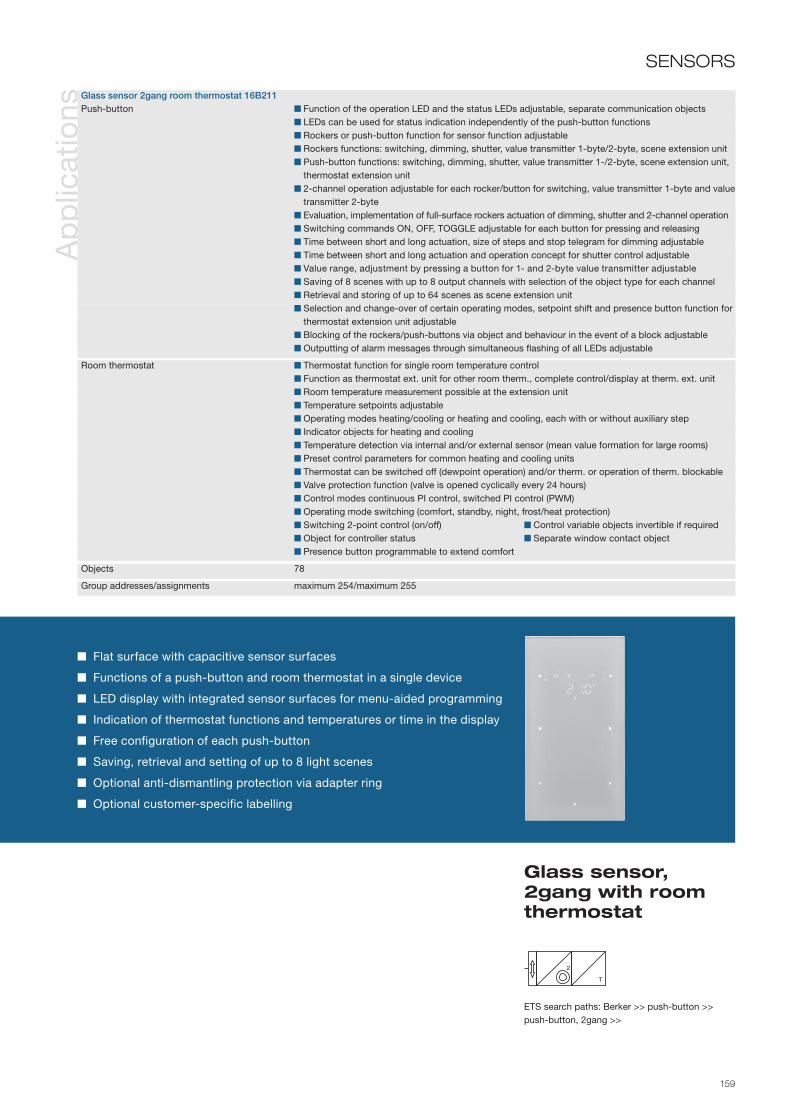
159
2
T
Flat surface with capacitive sensor surfaces
Functions of a push-button and room thermostat in a single device
LED display with integrated sensor surfaces for menu-aided programming
Indication of thermostat functions and temperatures or time in the display
Free configuration of each push-button
Saving, retrieval and setting of up to 8 light scenes
Optional anti-dismantling protection via adapter ring
Optional customer-specific labelling
SENSORS
ETS search paths: Berker >> push-button >> push-button, 2gang >>
Glass sensor, 2gang with room thermostat
Ap
plic
atio
nsGlass sensor 2gang room thermostat 16B211Push-button Function of the operation LED and the status LEDs adjustable, separate communication objects LEDs can be used for status indication independently of the push-button functions Rockers or push-button function for sensor function adjustable Rockers functions: switching, dimming, shutter, value transmitter 1-byte/2-byte, scene extension unit Push-button functions: switching, dimming, shutter, value transmitter 1-/2-byte, scene extension unit,
thermostat extension unit 2-channel operation adjustable for each rocker/button for switching, value transmitter 1-byte and value
transmitter 2-byte Evaluation, implementation of full-surface rockers actuation of dimming, shutter and 2-channel operation Switching commands ON, OFF, TOGGLE adjustable for each button for pressing and releasing Time between short and long actuation, size of steps and stop telegram for dimming adjustable Time between short and long actuation and operation concept for shutter control adjustable Value range, adjustment by pressing a button for 1- and 2-byte value transmitter adjustable Saving of 8 scenes with up to 8 output channels with selection of the object type for each channel Retrieval and storing of up to 64 scenes as scene extension unit Selection and change-over of certain operating modes, setpoint shift and presence button function for
thermostat extension unit adjustable Blocking of the rockers/push-buttons via object and behaviour in the event of a block adjustable Outputting of alarm messages through simultaneous flashing of all LEDs adjustable
Room thermostat Thermostat function for single room temperature control Function as thermostat ext. unit for other room therm., complete control/display at therm. ext. unit Room temperature measurement possible at the extension unit Temperature setpoints adjustable Operating modes heating/cooling or heating and cooling, each with or without auxiliary step Indicator objects for heating and cooling Temperature detection via internal and/or external sensor (mean value formation for large rooms) Preset control parameters for common heating and cooling units Thermostat can be switched off (dewpoint operation) and/or therm. or operation of therm. blockable Valve protection function (valve is opened cyclically every 24 hours) Control modes continuous PI control, switched PI control (PWM) Operating mode switching (comfort, standby, night, frost/heat protection) Switching 2-point control (on/off) Control variable objects invertible if required Object for controller status Separate window contact object Presence button programmable to extend comfort
Objects 78
Group addresses/assignments maximum 254/maximum 255

160
Info
rmat
ion
Tech
nica
l dat
a Supply via bus line 21–32 V DC
Operation and display elements 3 rockers each with left/right push-button 2 push-buttons integrated into the display at left and right
LC display 35 x 12.5 mm with symbols
Operation LED White
3 x 2 status LEDs at side Red
Connections Bus coupling unit plus flush-mounted AST: 2 x 5pole pin contact strip
Protection IP 20, EN 60529
Ambient temperature range Operation -5 to +45 °C Storage/transport -25 to +70 °C
Mounting Mount on bus coupling unit flush-mounted
Mounting orientation Display at top
Dimensions (WxHxD) see dimensional drawings
The push-button 3gang with room thermostat and display is a user module for mounting on the flush-mounted bus coupling unit, and combines the functions of a push-button, room thermostat and timer. The push-button room thermostat has an LC display for indicating temperatures and thermostat functions. Two additional push-buttons are integrated in the display at the right and left so that functions such as setpoint temperature, operating mode and room temperature timer can not only be read off, but so that their programming can be modified by the user with the aid of menus.The new push-button generation is designed without a central web, which means that large rockers are available for convenient operation. The push-button distinguishes between each actuation of the right-hand and left-hand sides of the rocker (2 buttons). The rocker cover is removable, the entire surface of the rocker is available for inserting a labelling plate. By arranging the operation LED at the lower edge and the status LEDs on the side edges of the rocker, the entire rocker surface is kept open for labelling. The austere, minimalistic form is superbly suited to the series' form language.
Ord
er d
ata Berker
S.1/B.1/B.3/B.7 GLASfor White and Polar white ...............
for Anthracite and Aluminium ................
7566 37 80
7566 37 85
Berker K.1/K.5for White and Polar white ..............
Anthracite ................
Aluminium ................
Stainless steel .........
7566 37 70
7566 37 75
7566 37 74
7566 37 73

161
3
T
SENSORS
ETS search paths: Berker >> Push-button >> Push-button, 3gang >>
Push-button 3gang with room thermo- stat and display
Ap
plic
atio
ns
Multifunction RTR + display 16A301 Push-button Control concept for each rocker adjustable as 2 push-buttons (2 objects) or rocker (1 object + 1 status object) Free assignment of the function to the push-buttons Switching/push-button (ON, OFF, CHANGE, no function) Dimming with stop telegram, telegram repetition, one push-button operation Shutter push-button function (UP, DOWN, CHANGE) and control concept adjustable 8 independent internal scenes with operation of 8 objects can be set Value transmitter EIS 6 (1-byte), light scene call with and without memory function, value transmitter 2-byte Function "2 Telegrams", sending of two different switching/ value telegrams per press of the push-button Operating mode switching for thermostat operation Status LED per push-button and operation LED
Room thermostat Thermostat function for single room temperature control Function as thermostat extension unit for other room thermostats, complete control /display at the thermostat extension unit Room temperature measurement possible at the extension unit Temperature setpoints Operating modes heating/cooling or heating and cooling, each with or without auxiliary step Indicator objects for heating and cooling Temperature detection via internal and/or external sensor (mean value formation for large rooms) Preset control parameter for common heating and cooling units Thermostat can be switched off (dewpoint operation) and/or thermostat or operation of thermostat blockable Valve protection function (valve is opened cyclically every 24 hours) Control modes continuous PI control, switched PI control (PWM) Operating mode switch-over (comfort, standby, night, frost/heat protection) Switching 2-point control (on/off) Control variable objects invertible if required Object for controller status Separate window contact object Presence button programmable to extend comfort
Room temperature timer Time-dependent adjustment of the operating modes comfort, standby, night operation Weekly program with up to 28 switching times Blocking of the push-button via object
Objects 77
Group addresses/assignments maximum 75/maximum 200
Functions of a push-button, room thermostat and room temperature timer in a single device
LC display with integrated push-buttons for menu-aided programming
Indication of thermostat functions, temperatures and time in the display
Free configuration of each push-button
One status LED per push-button
Push-button manually blockable
Integrated anti-dismantling protection

162
Info
rmat
ion
Ord
er d
ata
Tech
nica
l dat
a Supply via bus line 21–32 V DC
Operation and display elements 3 rockers each with left/right push-button 2 buttons integrated on left and right of display Graphic display 120 x 16 pixel black with characters lit up white Operation LED Blue 6 lateral status LEDs White
Connections Bus coupling unit plus, flush-mounted PEI: 2 x 5-pin male connectors
Protection IP 20, EN 60529
Ambient temperature range Operation -5 to +45 °C Storage/transport -25 to +70 °C
Mounting Bolting to flush-mounted bus coupling unit plus
Mounting orientation Display at top
Dimensions (WxHxD) see dimensions diagrams
BERKER B.IQPolar white ..............
Stainless steel .........
Glass, polar white....
7566 35 99
7566 35 93
7566 35 91
AccessoriesLabelling fieldclear transparent ..... 7590 00 80
The push-button 3gang with room thermostat and display is a user module for bolting to the flush-mounted bus coupling unit plus and combines the functions of a push-button, room thermostat, weekly timer and display unit. The push-button RTR possesses a graphic display with one symbol and two text lines. There are two additional buttons integrated on the left and right of the display. These allow the user not only to read off functions such as the set temperature, operating mode, timer etc. but also to influence their programming by means of menus.
The B.IQ has no frames. This means that large rockers are available to ensure ease of operation. The push-button RTR distinguishes between activation of the right and left side of the rocker. The button for each side of the rocker can be programmed separately.
The status LEDs are arranged on the side of the push-button RTR. This allows them to light up the optional labelling field by displaying switching statuses, for example.
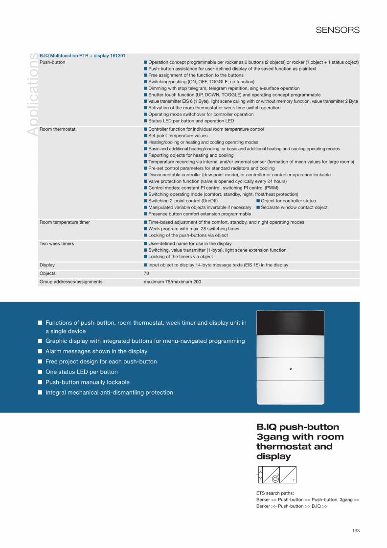
163
SENSORS
ETS search paths:Berker >> Push-button >> Push-button, 3gang >> Berker >> Push-button >> B.IQ >>
B.IQ push-button 3gang with room thermostat and display
Ap
plic
atio
nsB.IQ Multifunction RTR + display 161301 Push-button Operation concept programmable per rocker as 2 buttons (2 objects) or rocker (1 object + 1 status object) Push-button assistance for user-defined display of the saved function as plaintext Free assignment of the function to the buttons Switching/pushing (ON, OFF, TOGGLE, no function) Dimming with stop telegram, telegram repetition, single-surface operation Shutter touch function (UP, DOWN, TOGGLE) and operating concept programmable Value transmitter EIS 6 (1 Byte), light scene calling with or without memory function, value transmitter 2 Byte Activation of the room thermostat or week time switch operation Operating mode switchover for controller operation Status LED per button and operation LED
Room thermostat Controller function for individual room temperature control Set point temperature values Heating/cooling or heating and cooling operating modes Basic and additional heating/cooling, or basic and additional heating and cooling operating modes Reporting objects for heating and cooling Temperature recording via internal and/or external sensor (formation of mean values for large rooms) Pre-set control parameters for standard radiators and cooling Disconnectable controller (dew point mode), or controller or controller operation lockable Valve protection function (valve is opened cyclically every 24 hours) Control modes: constant PI control, switching PI control (PWM) Switching operating mode (comfort, standby, night, frost/heat protection) Switching 2-point control (On/Off) Object for controller status Manipulated variable objects invertable if necessary Separate window contact object Presence button comfort extension programmable
Room temperature timer Time-based adjustment of the comfort, standby, and night operating modes Week program with max. 28 switching times Locking of the push-buttons via object
Two week timers User-defined name for use in the display Switching, value transmitter (1-byte), light scene extension function Locking of the timers via object
Display Input object to display 14-byte message texts (EIS 15) in the display
Objects 70
Group addresses/assignments maximum 75/maximum 200
Functions of push-button, room thermostat, week timer and display unit in a single device
Graphic display with integrated buttons for menu-navigated programming
Alarm messages shown in the display
Free project design for each push-button
One status LED per button
Push-button manually lockable
Integral mechanical anti-dismantling protection
3
T

164
Info
rmat
ion
Ord
er d
ata
Tech
nica
l dat
a Supply via bus line 21–32 V DC
Operation and display elements 3 rockers each with left/right push-button 2 push-buttons integrated into the display at left and right graphical display 120 x 16 pixels black with white lit characters Operation LED Blue 6 status LEDs at side White
Connections Bus coupling unit plus flush-mounted AST: 2 x 5pole pin contact strip
IR code RC 5
Protection IP 20, EN 60529
Ambient temperature range Operation -5 to +45 °C Storage/transport -25 to +70 °C
Mounting Bolting to flush-mounted bus coupling unit
Mounting orientation Display at top
Dimensions (WxHxD) see dimensional drawings
BERKER B.IQPolar white ..............
Stainless steel .........
Glass, polar white....
7566 36 99
7566 36 93
7566 36 91
AccessoriesLabelling fieldclear transparent .....
IR hand-held transmitter ...............
7590 00 80
2779
The IR push-button 3gang with room thermostat and display is a user module for bolting to the flush-mounted bus coupling unit plus and combines the functions of a push-button, room thermostat, week time switch and display unit. The IR push-button room thermostat has a graphical display with one symbol line and two text lines. Two additional push-buttons are integrated in the display at the right and left so that functions such as setpoint temperature, operating mode, timers, etc. can not only be read off, but so that their programming can be modified by the user with the aid of menus.
The B.IQ is designed without a frame, which means that large rockers are available for convenient operation. The IR push-button room thermostat distinguishes between actuation of the right-hand and left-hand sides of the rocker. Each of the corresponding push-buttons can be programmed separately. The function of each push-button can be triggered with an RC 5 IR remote control via an assigned remote control push-button.
The status LEDs are arranged at the side of the IR push-button room thermostat so that they also illuminate the optional labelling field.

165
3
T
SENSORS
ETS search paths: Berker >> Push-button >> Push-button, 3gang >>Berker >> Push-button >> B.IQ >>
B.IQ IR push-button 3gang with room ther-mostat and display
Ap
plic
atio
nsB.IQ multifunction RTR + display + IR 163301 Push-button Control concept for each rocker adjustable as 2 push-buttons (2 objects) or rocker (1 object + 1 status object) Push-button assistance for user-defined plain text display of the underlying function Dimming with stop telegram, telegram repetition, one push-button operation Shutter push-button function (UP, DOWN, CHANGE) and control concept adjustable Value transmitter EIS 6 (1-byte), light scene call with and without memory function, value transmitter 2-byte Activation of operation of room temperature or week time switch Free assignment of the function to the push-buttons Switching/push-button (ON, OFF, CHANGE, no function) Operating mode switching for thermostat operation Status LED per push-button and operation LED
Room thermostat Thermostat function for single room temperature control Function as thermostat extension unit for other room thermostats, complete control/display at the thermostat extension unit Room temperature measurement possible at the extension unit Temperature setpoints Operating modes heating/cooling or heating and cooling Operating modes basic and additional heating/cooling or basic and additional heating and cooling Indicator objects for heating and cooling Temperature detection via internal and/or external sensor (mean value formation for large rooms) Preset control parameter for common heating and cooling units Thermostat can be switched off (dewpoint operation) and/or thermostat or operation of thermostat blockable Valve protection function (valve is opened cyclically every 24 hours) Control modes continuous PI control, switched PI control (PWM) Operating mode switching (comfort, standby, night, frost/heat protection) Switching 2-point control (on/off) Control variable objects invertible if required Object for controller status Separate window contact object Presence button programmable to extend comfort
Room temperature timer Time-dependent adjustment of the operating modes comfort, standby, night operation Weekly program with up to 28 switching times Blocking of the push-button via object
Two week time switches User-defined name for indication in display Blocking of the time switches via object Function switching, value transmitter (1-byte), light scene extension unit
Display Input object for indication of 14-byte message texts (EIS 15) in the display
IR Selection of the triggering device group of an IR remote control (RC 5) Free assignment of supported remote control push-buttons to function keys of the push-button
Objects 70
Group addresses/assignments maximum 75/maximum 200
Functions of a push-button, room thermostat, week time switch and display unit in a single device
Graphical display with integrated push-buttons for menu-aided programming
Indication of alarm messages in the display
Free configuration of each push-button
One status LED per push-button
Can be operated via IR remote control
Push-button manually blockable
Integrated anti-dismantling protection

166
Info
rmat
ion
Tech
nica
l dat
a Supply via bus line 21–32 V DC Power consumption KNX/EIB typ. 150 mW
Operation and display elements 3 rockers each with left/right push-button 2 push-buttons integrated into the display at left and right LC display 35 x 12.5 mm with symbol display Operation LED white 3 x 2 status LEDs orange
Connections KNX/EIB Connection terminal
Protection class IP 20, EN 60 529
Ambient temperature range Operation -5 to +45 °C Storage/transport -25 to +70 °C
Mounting Built into flush-mounted box Ø 60 mm
Mounting orientation Display at top
Dimensions (WxHxD) Installation depth approx. 23 mm Assembling height from wall approx. 13 mm
The push-button room thermostat, display is designed as a monoblock, i.e. with integrated bus coupling unit. The device can be connected directly to the bus line for commissioning. It combines the functions of a push-button, room thermostat and time switch. The push-button room thermostat has an LC display for indicating temperatures and thermostat functions. Two additional push-buttons are integrated into the display at the right and left so that functions such as setpoint temperature, operating mode and room temperature timer can not only be read off, but so that their programming can be modified by the user with the aid of menus.
The new push-button generation is designed without a central web, which means that large rockers are available for convenient operation. The push-button distinguishes between actuation of the right-hand and left-hand sides of the rocker (2 buttons). The cover is removable, the entire surface of the rocker is available for inserting a labelling plate.
Ord
er d
ata BERKER Q.1
Polar white, velvety ... 7566 37 29AccessoriesLabelling fieldsheets ...................... 9498 32 02

167
3
T
SENSORS
ETS search paths: Berker >> push-button >> push-button, 3gang >>
Push-button 3gang with labelling fields, room thermostat, display and bus coupling unit
Ap
plic
atio
ns
Multifunction room thermostat + display 16A301 Push-button Control concept for each rocker adjustable as 2 push-buttons (2 objects) or rocker (1 object + 1 status
object) Free assignment of the function to the push-buttons Switching/push-button (ON, OFF, TOGGLE, no function) Dimming with stop telegram, telegram repetition, one push-button operation Shutter push-button function (UP, DOWN, TOGGLE) and control concept adjustable 8 independent internal scenes with operation of 8 objects can be set Value transmitter EIS 6 (1-byte), light scene call with and without memory function, value transmitter
2-byte Function "2 telegrams", sending of two different switching/value telegrams per press of the push-button Operating mode switching for thermostat operation Status LED per push-button and operation LED
Room thermostat Thermostat function for single room temperature control Function as thermostat extension for other room thermostats, complete control/display at the thermostat
extension unit Room temperature measurement possible at the extension unit Temperature setpoints adjustable Operating modes heating/cooling or heating and cooling, each with or without auxiliary step Indicator objects for heating and cooling Temperature detection via internal and/or external sensor (mean value formation for large rooms) Preset control parameters for common heating and cooling units Thermostat can be switched off (dewpoint operation) and/or thermostat or operation of thermostat
blockable Valve protection function (valve is opened cyclically every 24 hours) Control modes continuous PI control, switched PI control (PWM) Operating mode switching (comfort, standby, night, frost/heat protection) Control variable objects invertible if required Switching 2-point control (on/off) Object for controller status Separate window contact object Presence button programmable to extend comfort
Room temperature timer Time-dependent adjustment of the operating modes comfort, standby, night operation Weekly program with up to 28 switching times Blocking of the push-button via object
Objects 77
Group addresses/assignments maximum 75/maximum 200
Functions of a push-button, room thermostat and room temperature timer in a single device
LC display with integrated push-buttons for menu-aided programming
Indication of thermostat functions and temperatures or time in the display
Free configuration of each push-button
Assignment of one status LED to each of the two push-buttons
Saving, retrieval and setting of up to 8 light scenes
Push-button or individual rockers/buttons lockable
Integrated anti-dismantling protection

168
Info
rmat
ion
Ord
er d
ata
Tech
nica
l dat
a
The glass sensor with room thermostat is intended for flush-mounted installation, and combines the functions of a push-button and a room thermostat. The glass sensor does not have any mechanical operating elements. Actuation is detected via capacitive sensor surfaces, and the LEDs are applied directly to the back of the glass plate, making the surface completely flat. Yet the glass sensor still provides the usual convenient opera-tion. Pairs of operating surfaces can be joined logically into rockers, the LEDs next to the sensor surfaces can be controlled individually to indicate the status.
The glass sensor room thermostat also has an LED display for indicating temperatures and thermostat functions. Two additional sensor surfaces are integrated into the display at the right and left which enable functions such as setpoint temperature and operating mode to be modified by the user with the aid of menus.
Supply Operating voltage 8 – 30 V DC via separate power supply Power consumption max. 0.5 W via bus line 21 - 32 V DC Power consumption KNX typ. 150 mW
Operation and display elements 3 x 2 sensor surfaces each left/right 2 sensor surfaces integrated into the display at left and right LED display with symbol display Operation LED blue 3 x 2 status-LEDs white
Connections KNX/EIB Connection terminal Power supply Connection terminal
Protection class IP 20, EN 60 529 Safety class III
Ambient temperature range Operation -5 to +45 °C Storage/transport -25 to +70 °C
Installation Snap onto wall box (order no. 1870) Adapter ring for anti-dismantling protection optional
Dimensions Glass plate 160 x 86 x 4 mm Assembling height from wall 4.7 mm (seated on wall) 10.7 mm (with adapter ring) Surface compensation max. 20 mm
BERKER TS SensorGlass, polar white....
Glass, black.............
Glass, aluminium .....
with configured labelling ...................
7564 30 39
7564 30 35
7564 30 34
7564 31 3x
AccessoriesWall box 2gang for glass sensor ........... 1870

169
3
T
Flat surface with capacitive sensor surfaces
Functions of a push-button and room thermostat in a single device
LED display with integrated sensor surfaces for menu-aided programming
Indication of thermostat functions and temperatures or time in the display
Free configuration of each push-button
Saving, retrieval and setting of up to 8 light scenes
Optional anti-dismantling protection via adapter ring
Optional customer-specific labelling
SENSORS
ETS search paths: Berker >> push-button >> push-button, 3gang >>
Glass sensor, 3gang with room thermostat
Ap
plic
atio
nsGlass sensor 3gang room thermostat 16B311Push-button Function of the operation LED and the status LEDs adjustable, separate communication objects LEDs can be used for status indication independently of the push-button functions Rockers or push-button function for sensor function adjustable Rockers functions: switching, dimming, shutter, value transmitter 1-byte/2-byte, scene extension unit Push-button functions: switching, dimming, shutter, value transmitter 1-/2-byte, scene extension unit,
thermostat extension unit 2-channel operation adjustable for each rocker/button for switching, value transmitter 1-byte and value
transmitter 2-byte Evaluation, implementation of full-surface rockers actuation of dimming, shutter and 2-channel operation Switching commands ON, OFF, TOGGLE adjustable for each button for pressing and releasing Time between short and long actuation, size of steps and stop telegram for dimming adjustable Time between short and long actuation and operation concept for shutter control adjustable Value range, adjustment by pressing a button for 1- and 2-byte value transmitter adjustable Saving of 8 scenes with up to 8 output channels with selection of the object type for each channel Retrieval and storing of up to 64 scenes as scene extension unit Selection and change-over of certain operating modes, setpoint shift and presence button function for
thermostat extension unit adjustable Blocking of the rockers/push-buttons via object and behaviour in the event of a block adjustable Outputting of alarm messages through simultaneous flashing of all LEDs adjustable
Room thermostat Thermostat function for single room temperature control Function as thermostat extension unit for other room thermostats, complete control/display at
thermostat extension unit Room temperature measurement possible at the extension unit Temperature setpoints adjustable Operating modes heating/cooling or heating and cooling, each with or without auxiliary step Indicator objects for heating and cooling Temperature detection via internal and/or external sensor (mean value formation for large rooms) Preset control parameters for common heating and cooling units Thermostat can be switched off (dewpoint operation) and/or therm. or operation of therm. blockable Valve protection function (valve is opened cyclically every 24 hours) Control modes continuous PI control, switched PI control (PWM) Operating mode switching (comfort, standby, night, frost/heat protection) Control variable objects invertible if required Switching 2-point control (on/off) Object for controller status Separate window contact object Presence button programmable to extend comfort
Objects; group addresses/assignments 84; maximum 254/maximum 255

170
Info
rmat
ion
Ord
er d
ata
Tech
nica
l dat
a Supply via bus line 21–32 V DC
Operation and display elements 4 rockers each with left/right push-button 2 buttons integrated on left and right of display Graphic display 120 x 16 pixel black with characters lit up white Operation LED Blue 8 lateral status LEDs White
Connections Bus coupling unit plus, flush-mounted PEI: 2 x 5-pin male connectors
Protection IP 20, EN 60529
Ambient temperature range Operation -5 to +45 °C Storage/transport -25 to +70 °C
Mounting Bolting to flush-mounted bus coupling unit plus
Mounting orientation Display at top
Dimensions (WxHxD) see dimensions diagrams
BERKER B.IQPolar white ..............
Stainless steel .........
Glass, polar white....
7566 45 99
7566 45 93
7566 45 91
AccessoriesLabelling fieldclear transparent ..... 7590 00 81
The push-button 4gang with room thermostat and display is a user module for bolting to the flush-mounted bus coupling unit plus. It combines the functions of push-button, room thermostat, weekly timer and display unit. The push-button RTR possesses a graphic display with one symbol and two text lines. There are two additional buttons integrated on the left and right of the display. These allow the user not only to read off functions such as the set temperature, operating mode, timer etc. but also to influence their programming by means of menus.
The B.IQ has no frames. This means that large rockers are available to ensure ease of operation. The push-button RTR distinguishes between activation of the right and left side of the rocker. The button for each side of the rocker can be programmed separately.
The status LEDs are arranged on the side of the push-button RTR. This allows them to light up the optional labelling field by displaying switching statuses, for example.

171
SENSORS
ETS search paths: Berker >> Push-button >> Push-button, 4gang >> Berker >> Push-button >> B.IQ >>
B.IQ push-button 4gang with room thermostat and display
Ap
plic
atio
nsB.IQ Multifunction RTR + display 161401 Push-button Operation concept programmable per rocker as 2 buttons (2 objects) or rocker (1 object + 1 status object) Push-button assistance for user-defined display of the saved function as plaintext Free assignment of the function to the buttons Switching/pushing (ON, OFF, TOGGLE, no function) Dimming with stop telegram, telegram repetition, single-surface operation Shutter touch function (UP, DOWN, TOGGLE) and operating concept programmable Value transmitter EIS 6 (1-byte), light scene calling with or without memory function, value transmitter 2-byte Activation of the room thermostat or week time switch operation Operating mode switchover for controller operation Status LED per button and operation LED
Room thermostat Controller function for individual room temperature control Set point temperature values Heating/cooling or heating and cooling operating modes Basic and additional heating/cooling, or basic and additional heating and cooling operating modes Reporting objects for heating and cooling Temperature recording via internal and/or external sensor (formation of mean values for large rooms) Pre-set control parameters for standard radiators and cooling Disconnectable controller (dew point mode), or controller or controller operation lockable Valve protection function (valve is opened cyclically every 24 hours) Control modes: constant PI control, switching PI control (PWM) Switching operating mode (comfort, standby, night, frost/heat protection) Switching 2-point control (On/Off) Object for controller status Manipulated variable objects invertable if necessary Separate window contact object Presence button comfort extension programmable
Room temperature timer Time-based adjustment of the comfort, standby, and night operating modes Week program with max. 28 switching times Locking of the push-buttons via object
Two week timers User-defined name for use in the display Switching, value transmitter (1-byte), light scene extension function Locking of the timers via object
Display Input object to display 14-byte message texts (EIS 15) in the display
Objects 70
Group addresses/assignments maximum 75/maximum 200
Functions of push-button, room thermostat, week timer and display unit in a single device
Graphic display with integrated buttons for menu-navigated programming
Alarm messages shown in the display
Free project design for each push-button
One status LED per button
Push-button manually lockable
Integral mechanical anti-dismantling protection
4
T

172
Info
rmat
ion
Ord
er d
ata
Tech
nica
l dat
a Supply via bus line 21–32 V DC
Operation and display elements 4 rockers each with left/right push-button 2 push-buttons integrated into the display at left and right graphical display 120 x 16 pixels black with white lit characters Operation LED Blue 8 status LEDs at side White
Connections Bus coupling unit plus flush-mounted AST: 2 x 5pole pin contact strip
IR code RC 5
Protection IP 20, EN 60529
Ambient temperature range Operation -5 to +45 °C Storage/transport -25 to +70 °C
Installation Bolting to flush-mounted bus coupling unit
Mounting orientation Display at top
Dimensions (WxHxD) see dimensional drawings
BERKER B.IQPolar white ..............
Stainless steel .........
Glass, polar white....
7566 46 99
7566 46 93
7566 46 91
AccessoriesLabelling fieldclear transparent .....
IR hand-held transmitter ...............
7590 00 81
2779
The IR push-button 4gang with room thermostat and display is a user module for bolting to the flush-mounted bus coupling unit plus and combines the functions of a push-button, room thermostat, weekly timer and display unit. The IR push-button room thermostat has a graphical display with one symbol line and two text lines. Two additional push-buttons are integrated in the display at the right and left so that functions such as setpoint temperature, operating mode, timers, etc. can not only be read off, but so that their pro gramming can be modified by the user with the aid of menus.
The B.IQ is designed without a frame, which means that large rockers are available for convenient operation. The IR push-button room thermostat distinguishes between actuation of the right-hand and left-hand sides of the rocker. Each of the corresponding push-buttons can be programmed separately. The function of each push-button can be triggered with an RC 5 IR remote control via an assigned remote control push-button.
The status LEDs are arranged at the side of the IR push-button room thermostat so that they also illuminate the optional labelling field together with the display of switching states, etc.

173
4
T
SENSORS
ETS search paths: Berker >> Push-button >> Push-button, 4gang >>Berker >> Push-button >> B.IQ >>
B.IQ IR push-button 4gang with room ther-mostat and display
Ap
plic
atio
nsB.IQ multifunction RTR + display + IR 163401 Push-button Control concept for each rocker adjustable as 2 push-buttons (2 objects) or rocker (1 object + 1 status object) Push-button assistance for user-defined plain text display of the underlying function Dimming with stop telegram, telegram repetition, one push-button operation Shutter push-button function (UP, DOWN, CHANGE) and control concept adjustable Value transmitter EIS 6 (1-byte), light scene call with and without memory function, value transmitter 2-byte Activation of operation of room temperature or week time switch Free assignment of the function to the push-buttons Switching/push-button (ON, OFF, CHANGE, no function) Operating mode switching for thermostat operation Status LED per push-button and operation LED
Room thermostat Thermostat function for single room temperature control Function as thermostat extension unit for other room thermostats, complete control/display at the thermostat extension unit Room temperature measurement possible at the extension unit Temperature setpoints Operating modes heating/cooling or heating and cooling Operating modes basic and additional heating/cooling or basic and additional heating and cooling Indicator objects for heating and cooling Temperature detection via internal and/or external sensor (mean value formation for large rooms) Preset control parameter for common heating and cooling units Thermostat can be switched off (dewpoint operation) and/or thermostat or operation of thermostat blockable Valve protection function (valve is opened cyclically every 24 hours) Control modes continuous PI control, switched PI control (PWM) Operating mode switching (comfort, standby, night, frost/heat protection) Switching 2-point control (on/off) Control variable objects invertible if required Object for controller status Separate window contact object Presence button programmable to extend comfort
Room temperature timer Time-dependent adjustment of the operating modes comfort, standby, night operation Weekly program with up to 28 switching times Blocking of the push-button via object
Two week time switches User-defined name for indication in display Blocking of the time switches via object Function switching, value transmitter (1-byte), light scene extension unit
Display Input object for indication of 14-byte message texts (EIS 15) in the display
IR Selection of the triggering device group of an IR remote control (RC 5) Free assignment of supported remote control push-buttons to function keys of the push-button
Objects 70
Group addresses/assignments maximum 75/maximum 200
Functions of a push-button, room thermostat, week time switch and display unit in a single device
Graphical display with integrated push-buttons for menu-aided programming
Indication of alarm messages in the display
Free configuration of each push-button
One status LED per push-button
Can be operated via IR remote control
Push-button manually blockable
Integrated anti-dismantling protection
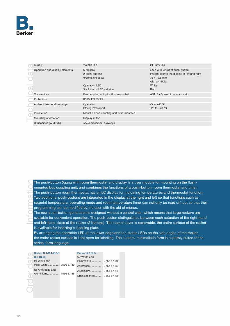
174
Info
rmat
ion
Tech
nica
l dat
a Supply via bus line 21–32 V DC
Operation and display elements 5 rockers each with left/right push-button 2 push-buttons integrated into the display at left and right graphical display 35 x 12.5 mm with symbols Operation LED White 5 x 2 status LEDs at side Red
Connections Bus coupling unit plus flush-mounted AST: 2 x 5pole pin contact strip
Protection IP 20, EN 60529
Ambient temperature range Operation -5 to +45 °C Storage/transport -25 to +70 °C
Installation Mount on bus coupling unit flush-mounted
Mounting orientation Display at top
Dimensions (WxHxD) see dimensional drawings
The push-button 5gang with room thermostat and display is a user module for mounting on the flush- mounted bus coupling unit, and combines the functions of a push-button, room thermostat and timer. The push-button room thermostat has an LC display for indicating temperatures and thermostat function. Two additional push-buttons are integrated in the display at the right and left so that functions such as setpoint temperature, operating mode and room temperature timer can not only be read off, but so that their programming can be modified by the user with the aid of menus.The new push-button generation is designed without a central web, which means that large rockers are available for convenient operation. The push-button distinguishes between each actuation of the right-hand and left-hand sides of the rocker (2 buttons). The rocker cover is removable, the entire surface of the rocker is available for inserting a labelling plate. By arranging the operation LED at the lower edge and the status LEDs on the side edges of the rocker, the entire rocker surface is kept open for labelling. The austere, minimalistic form is superbly suited to the series' form language.
Ord
er d
ata Berker S.1/B.1/B.3/
B.7 GLASfor White and Polar white ...............
for Anthracite and Aluminium ................
7566 57 80
7566 57 85
Berker K.1/K.5for White and Polar white ..............
Anthracite ................
Aluminium ................
Stainless steel .........
7566 57 70
7566 57 75
7566 57 74
7566 57 73

175
5
T
SENSORS
ETS search paths: Berker >> Push-button >> Push-button, 5gang >>
Push-button 5gang with room thermo-stat and display
Ap
plic
atio
ns
Multifunction RTR + display 16A501 Push-button Control concept for each rocker adjustable as 2 push-buttons (2 objects) or rocker (1 object + 1 status object) Free assignment of the function to the push-buttons Switching/push-button (ON, OFF, CHANGE, no function) Dimming with stop telegram, telegram repetition, one push-button operation Shutter push-button function (UP, DOWN, CHANGE) and control concept adjustable 8 independent internal scenes with operation of 8 objects can be set Value transmitter EIS 6 (1-byte), light scene call with and without memory function, value transmitter 2-byte Function "2 Telegrams", sending of two different switching/ value telegrams per press of the push-button Operating mode switching for thermostat operation Status LED per push-button and operation LED
Room thermostat Thermostat function for single room temperature control Function as thermostat extension unit for other room thermostats, complete control/display at the thermostat extension unit Room temperature measurement possible at the extension unit Temperature setpoints Operating modes heating/cooling or heating and cooling, each with or without auxiliary step Indicator objects for heating and cooling Temperature detection via internal and/or external sensor (mean value formation for large rooms) Preset control parameter for common heating and cooling units Thermostat can be switched off (dewpoint operation) and/or thermostat or operation of thermostat blockable Valve protection function (valve is opened cyclically every 24 hours) Control modes continuous PI control, switched PI control (PWM) Operating mode switch-over (comfort, standby, night, frost/heat protection) Switching 2-point control (on/off) Control variable objects invertible if required Object for controller status Separate window contact object Presence button programmable to extend comfort
Room temperature timer Time-dependent adjustment of the operating modes comfort, standby, night operation Weekly program with up to 28 switching times Blocking of the push-button via object
Objects 77
Group addresses/assignments maximum 75/maximum 200
Functions of a push-button, room thermostat and room temperature timer in a single device
LC display with integrated push-buttons for menu-aided programming
Indication of thermostat functions, temperatures and time in the display
Free configuration of each push-button
One status LED per push-button
Push-button manually blockable
Integrated anti-dismantling protection

176
Info
rmat
ion
Ord
er d
ata
Tech
nica
l dat
a Supply via bus line 21–32 V DC
Operation and display elements 5 rockers each with left/right push-button 2 buttons integrated on left and right of display Graphic display 120 x 16 pixel black with characters lit up white Operation LED Blue 10 lateral status LEDs White
Connections Bus coupling unit plus, flush-mounted PEI: 2 x 5-pin male connectors
Protection IP 20, EN 60529
Ambient temperature range Operation -5 to +45 °C Storage/transport -25 to +70 °C
Mounting Bolting to flush-mounted bus coupling unit plus
Mounting orientation Display at top
Dimensions (WxHxD) see dimensions diagrams
BERKER B.IQ Polar white ..............
Stainless steel .........
Glass, Polar white ...
7566 55 99
7566 55 93
7566 55 91
AccessoriesLabelling fieldclear transparent ..... 7590 00 82
The push-button 5gang with room thermostat and display is a user module for bolting to a flush-mounted bus coupling unit plus. It combines the functions of push-button, room thermostat, week timer and display unit. The push-button RTR possesses a graphic display with one symbol and two text lines. There are two additional buttons integrated on the left and right of the display. These allow the user not only to read off functions such as the set temperature, operating mode, timer etc. but also to influence their programming by means of menus.
The B.IQ has no frames. This means that large rockers are available to ensure ease of operation. The push-button RTR distinguishes between activation of the right and left side of the rocker. The button for each side of the rocker can be programmed separately.
The status LEDs are arranged on the side of the push-button RTR. This allows them to light up the optional labelling field by displaying switching statuses, for example.
177
SENSORS
ETS search paths: Berker >>Push-button >> Push-button, 5gang >> Berker >> Push-button >> B.IQ >>
B.IQ push-button 5gang with room thermostat and display
Ap
plic
atio
nsB.IQ Multifunction RTR + display 161501 Push-button Operation concept programmable per rocker as 2 buttons (2 objects) or rocker (1 object + 1 status object) Push-button assistance for user-defined display of the saved function as plaintext Free assignment of the function to the buttons Switching/pushing (ON, OFF, TOGGLE, no function) Dimming with stop telegram, telegram repetition, single-surface operation Shutter touch function (UP, DOWN, TOGGLE) and operating concept programmable Value transmitter EIS 6 (1-byte), light scene calling with or without memory function, value transmitter 2-byte Activation of the room thermostat or week time switch operation Operating mode switchover for controller operation Status LED per button and operation LED
Room thermostat Controller function for individual room temperature control Set point temperature values Heating/cooling or heating and cooling operating modes Basic and additional heating/cooling, or basic and additional heating and cooling operating modes Reporting objects for heating and cooling Temperature recording via internal and/or external sensor (formation of mean values for large rooms) Pre-set control parameters for standard radiators and cooling Disconnectable controller (dew point mode), or controller or controller operation lockable Valve protection function (valve is opened cyclically every 24 hours) Control modes: constant PI control, switching PI control (PWM) Switching operating mode (comfort, standby, night, frost/heat protection) Switching 2-point control (On/Off) Object for controller status Manipulated variable objects invertable if necessary Separate window contact object Presence button comfort extension programmable
Room temperature timer Time-based adjustment of the comfort, standby, and night operating modes Week program with max. 28 switching times Locking of the push-buttons via object
Two week timers User-defined name for use in the display Switching, value transmitter (1-byte), light scene extension function Locking of the timers via object
Display Input object to display 14-byte message texts (EIS 15) in the display
Objects 70
Group addresses/assignments maximum 75/maximum 200
Functions of push-button, room thermostat, week timer and display unit in a single device
Graphic display with integrated buttons for menu-navigated programming
Alarm messages shown in the display
Free project design for each push-button
One status LED per button
Push-button manually lockable
Integral mechanical anti-dismantling protection
5
T

178
Info
rmat
ion
Ord
er d
ata
Tech
nica
l dat
a Supply via bus line 21–32 V DC
Operation and display elements 5 rockers each with left/right push-button 2 push-buttons integrated into the display at left and right graphical display 120 x 16 pixels black with white lit characters Operation LED Blue 10 status LEDs at side White
Connections Bus coupling unit plus flush-mounted AST: 2 x 5pole pin contact strip
IR code RC 5
Protection IP 20, EN 60529
Ambient temperature range Operation -5 to +45 °C Storage/transport -25 to +70 °C
Mounting Bolting to flush-mounted bus coupling unit
Mounting orientation Display at top
Dimensions (WxHxD) see dimensional drawings
BERKER B.IQPolar white ..............
Stainless steel .........
Glass, Polar white ...
7566 56 99
7566 56 93
7566 56 91
AccessoriesLabelling fieldclear transparent .....
IR hand-held transmitter ...............
7590 00 82
2779
The IR push-button 5gang with room thermostat and display is a user module for bolting to the flush- mounted bus coupling unit plus and combines the functions of a push-button, room thermostat, weekly timer and display unit. The IR push-button room thermostat has a graphical display with one symbol line and two text lines. Two additional push-buttons are integrated in the display at the right and left so that functions such as setpoint temperature, operating mode, timers, etc. can not only be read off, but so that their programming can be modified by the user with the aid of menus.
The B.IQ is designed without a frame, which means that large rockers are available for convenient operation. The IR push-button room thermostat distinguishes between actuation of the right-hand and left-hand sides of the rocker. Each of the corresponding push-buttons can be programmed separately. The function of each push-button can be triggered with an RC 5 IR remote control via an assigned remote control push-button.
The status LEDs are arranged at the side of the IR push-button room thermostat so that they also illuminate the optional labelling field together with the display of switching states, etc.

179
5
T
SENSORS
ETS search paths: Berker >> Push-button >> Push-button, 5gang >>Berker >> Push-button >> B.IQ >>
B.IQ IR push-button 5gang with room ther-mostat and display
Ap
plic
atio
nsB.IQ multifunction RTR + display + IR 163501 Push-button Control concept for each rocker adjustable as 2 push-buttons (2 objects) or rocker (1 object + 1 status object) Push-button assistance for user-defined plain text display of the underlying function Dimming with stop telegram, telegram repetition, one push-button operation Shutter push-button function (UP, DOWN, CHANGE) and control concept adjustable Value transmitter EIS 6 (1-byte), light scene call with and without memory function, value transmitter 2-byte Activation of operation of room temperature or week time switch Free assignment of the function to the push-buttons Switching/push-button (ON, OFF, CHANGE, no function) Operating mode switching for thermostat operation Status LED per push-button and operation LED
Room thermostat Thermostat function for single room temperature control Function as thermostat extension unit for other room thermostats, complete control/display at the thermostat extension unit Room temperature measurement possible at the extension unit Temperature setpoints Operating modes heating/cooling or heating and cooling Operating modes basic and additional heating/cooling or basic and additional heating and cooling Indicator objects for heating and cooling Temperature detection via internal and/or external sensor (mean value formation for large rooms) Preset control parameter for common heating and cooling units Thermostat can be switched off (dewpoint operation) and/or thermostat or operation of thermostat blockable Valve protection function (valve is opened cyclically every 24 hours) Control modes continuous PI control, switched PI control (PWM) Operating mode switch-over (comfort, standby, night, frost/heat protection) Switching 2-point control (on/off) Control variable objects invertible if required Object for controller status Separate window contact object Presence button programmable to extend comfort
Room temperature timer Time-dependent adjustment of the operating modes comfort, standby, night operation Weekly program with up to 28 switching times Blocking of the push-button via object
Two week time switches User-defined name for indication in display Blocking of the time switches via object Function switching, value transmitter (1-byte), light scene extension unit
Display Input object for indication of 14-byte message texts (EIS 15) in the display
IR Selection of the triggering device group of an IR remote control (RC 5) Free assignment of supported remote control push-buttons to function keys of the push-button
Objects 70
Group addresses/assignments maximum 75/maximum 200
Functions of a push-button, room thermostat, weekly timer and display unit in a single device
Graphical display with integrated push-buttons for menu-aided programming
Indication of alarm messages in the display
Free configuration of each push-button
One status LED per push-button
Can be operated via IR remote control
Push-button manually blockable
Integrated anti-dismantling protection
180
Info
rmat
ion
Tech
nica
l dat
a Supply via bus line 21–32 V DC Power consumption KNX/EIB typ. 150 mW
Operation and display elements 5 rockers each with left/right push-button 2 push-buttons integrated into the display at left and right LC display 35 x 12.5 mm with symbol display Operation LED white 5 x 2 status LEDs orange
Connections KNX/EIB Connection terminal
Protection class IP 20, EN 60 529
Ambient temperature range Operation -5 to +45 °C Storage/transport -25 to +70 °C
Mounting Built into flush-mounted box Ø 60 mm
Mounting orientation Display at top
Dimensions (WxHxD) Installation depth approx. 23 mm Assembling height from wall approx. 13 mm
The push-button room thermostat, display is designed as a monoblock, i.e. with integrated bus coupling unit. The device can be connected directly to the bus line for commissioning. It combines the functions of a push-button, room thermostat and time switch. The push-button room thermostat has an LC display for indicating temperatures and thermostat functions. Two additional push-buttons are integrated into the display at the right and left so that functions such as setpoint temperature, operating mode and room temperature timer can not only be read off, but so that their programming can be modified by the user with the aid of menus.
The new push-button generation is designed without a central web, which means that large rockers are availa-ble for convenient operation. The push-button distinguishes between actuation of the right-hand and left-hand sides of the rocker (2 buttons). The cover is removable, the entire surface of the rocker is available for inserting a labelling plate.
Ord
er d
ata BERKER Q.1
Polar white, velvety ... 7566 57 29AccessoriesLabelling fieldsheets ...................... 9498 31 03

181
5
T
SENSORS
ETS search paths: Berker >> push-button >> push-button, 5gang >>
Push-button 5gang with labelling fields, room thermostat, display and bus coupling unit
Ap
plic
atio
nsMultifunction room thermostat + display 16A501 Push-button Control concept for each rocker adjustable as 2 push-buttons (2 objects) or rocker (1 object + 1 status
object) Free assignment of the function to the push-buttons Switching/push-button (ON, OFF, TOGGLE, no function) Dimming with stop telegram, telegram repetition, one push-button operation Shutter push-button function (UP, DOWN, TOGGLE) and control concept adjustable 8 independent internal scenes with operation of 8 objects can be set Value transmitter EIS 6 (1-byte), light scene call with and without memory function, value transmitter
2-byte Function "2 telegrams", sending of two different switching/value telegrams per press of the push-
button Operating mode switching for thermostat operation Status LED per push-button and operation LED
Room thermostat Thermostat function for single room temperature control Function as thermostat extension for other room thermostats, complete control/display at the thermostat
extension unit Room temperature measurement possible at the extension unit Temperature setpoints adjustable Operating modes heating/cooling or heating and cooling, each with or without auxiliary step Indicator objects for heating and cooling Temperature detection via internal and/or external sensor (mean value formation for large rooms) Preset control parameters for common heating and cooling units Thermostat can be switched off (dewpoint operation) and/or thermostat or operation of thermostat
blockable Valve protection function (valve is opened cyclically every 24 hours) Control modes continuous PI control, switched PI control (PWM) Operating mode switching (comfort, standby, night, frost/heat protection) Control variable objects invertible if required Switching 2-point control (on/off) Object for controller status Separate window contact object Presence button programmable to extend comfort
Room temperature timer Time-dependent adjustment of the operating modes comfort, standby, night operation Weekly program with up to 28 switching times Blocking of the push-button via object
Objects 77
Group addresses/assignments maximum 75/maximum 200
Functions of a push-button, room thermostat and room temperature timer in a single device
LC display with integrated push-buttons for menu-aided programming
Indication of thermostat functions and temperatures or time in the display
Free configuration of each push-button
Assignment of one status LED to each of the two push-buttons
Saving, retrieval and setting of up to 8 light scenes
Push-button or individual rockers/buttons lockable
Integrated anti-dismantling protection

182
Info
rmat
ion
Ord
er d
ata
Tech
nica
l dat
a Supply via bus line 21–32 V DC
Operation and display elements 4 upper buttons 4 lower buttons Operation LED Green 8 status LEDs Red
Connections Bus coupling unit, flush-mounted PEI: 2 x 5-pin male connectors
Protection IP 20, EN 60529
Ambient temperature range Operation -5 to +45 °C Storage/transportation -25 to +70 °C
Mounting Clip onto bus coupling unit, flush-mounted
Mounting orientation any
Dimensions (WxHxD) see dimensional drawings
The light scene push-button comfort is clipped onto the flush-mounted bus coupling unit. When a button is pressed it sends KNX/EIB telegrams which cause actuators to trigger corresponding functions. Depending on the loaded application, up to eight light scenes can be stored and retrieved, or four telegram sequences with a maximum of eight outputs can be generated.
Each button is assigned an LED with programmable functions.
The push-button has two user levels which can be manually set. On the first user level the light scenes can be stored and retrieved, on the second user level the equipment can be adjusted; no additional sensors are needed.
The device is completed by a cover frame, the bus coupling unit and a terminal.
MODUL 2White .......................
Polar white ..............
7516 87 12
7516 87 19
Berker S.1/B.1/B.3/B.7 GLASPolar white, matt .....
Anthracite, matt .......
Aluminium, matt ......
7516 87 89
7516 87 85
7516 87 83
Berker ARSYSWhite .......................
Polar white ..............
Light bronze, lacquered ................
Stainless steel, lacquered ................
7516 87 42
7516 87 49
7516 87 44
7516 87 43

183
AccessoriesLabelling fieldwith cover plate
MODUL 2White .......................Polar white...............
Berker S.1/B.1/B.3/ B.7 GLASPolar white...............Aluminium ................Anthracite ................
7596 00 017596 00 02
7596 00 077596 00 097596 00 08
Berker ARSYSWhite .......................Polar white...............Light bronze, lacquered ................Stainless steel, lacquered .................
7596 00 037596 00 06
7596 00 05
7596 00 04
SENSORSA
pp
licat
ions
Light scene/dimming 106501 Lockout function via object Cascading of multiple light scene push-buttons Variable setting of status LED operation periods Second user level: Lamp setup Transmission of time-offset telegrams Dimmer function programmable Outputs can be removed separately from light scenes Dimmer function via single-area operation Extension function
Objects 20
Group addresses/assignments maximum of 22 each
Telegram sequence 106401 Alarm function in case push-button pulled off Four telegram sequences Random mode Endless mode Eight outputs Outputs lockable Extension function
Objects 10
Group addresses/assignments maximum of 10 each
ETS search path: Berker >> Push-button >> Push-buttons general >>
Light scene push-button comfort
Operation of switch, dim or shutter actuators
Operating and status LEDs to indicate operating states
Retrieval and storage of up to eight different light scenes
Value transmitter for brightness values
Operation on two switchable user levels
Alarm function in case of separation of push-button from bus coupling unit
Integral mechanical anti-dismantling protection
n

184
Info
rmat
ion
Tech
nica
l dat
a Supply via bus line 21–32 V DC
Operation and display elements 4 rockers each with left/right push-button Operation LED White 4 x 2 status LEDs at side Red
Connections Bus coupling unit flush-mounted AST: 2 x 5pole pin contact strip
Protection IP 20, EN 60529
Ambient temperature range Operation -5 to +45 °C Storage/transport -25 to +70 °C
Mounting Mount on bus coupling unit flush-mounted
Mounting orientation as desired
Dimensions (WxHxD) see dimensional drawings
The light scene push-button 8gang comfort is a user module for mounting on a flush-mounted bus coupling unit.
When pressed, the light scene push-button sends telegrams to the instabus KNX/EIB; these trigger the functions corresponding to the application that is loaded. The new push-button generation is designed without a central web, which means that large rockers are available for convenient operation.
The push-button distinguishes between each actuation of the right-hand and left-hand sides of the rocker (2 buttons). The rocker cover is removable, the entire surface of the rocker is available for inserting a labelling plate.
By arranging the operation LED at the lower edge and the status LEDs on the side edges of the rocker, the entire rocker surface is kept open for labelling. The austere, minimalistic form is superbly suited to the series' form language.
Ord
er d
ata Berker S.1/B.1/B.3/
B.7 GLASfor White and Polar white ..............
for Anthracite and Aluminium ...............
7516 88 80
7516 88 85
Berker K.1/K.5for White and Polar white ..............
Anthracite ................
Aluminium ...............
Stainless steel .........
7516 88 70
7516 88 75
7516 88 74
7516 88 73

185
8
Light scene push-button 8gang comfort
Activation of switch, dimmer or shutter actuators
Operation LED and status LEDs for indicating operating states
Calling up and saving up to eight different light scenes
Value transmitter for transmitting brightness values with eight outputs each
Operation in two transposable operating levels
Alarm function if the push-button is separated from the bus coupling unit
Integrated anti-dismantling protection
ETS search paths: Berker >> Push-button >> Push-button, general >>
Ap
plic
atio
ns
Light scene/dimming 106501 Object type switching or brightness value adjustable per output Blocking function via object Cascade operation of multiple light scene push-buttons Variable setting of the status LED with regard to the length of actuation Second operating level: Setting the lights to modify the light scene Sending of telegrams with time offset Dimmer adjustable Outputs can be removed separately from light scenes Dimmer via one push-button operation Extension unit function
Objects 20
Group addresses/assignments maximum 22 each
Telegram sequence 106401 Alarm function in the push-button is disconnected Object types 1-bit, 1-byte, 2-byte possible Four telegram sequences Sequence and times adjustable per telegram sequence Random mode Continuous operation Maximum of eight outputs Outputs blockable using push-button code (on-the-spot operation) Extension unit function
Objects 10
Group addresses/assignments maximum 10 each
SENSORS
8

186
Info
rmat
ion
The B.IQ light scene push-button comfort is a user module for bolting to a flush-mounted bus coupling unit. When a button is pressed, it sends KNX/EIB telegrams which cause actuators to trigger corresponding functions. Depending on the application which has been loaded, up to eight light scenes can be stored and retrieved, or four telegram sequences with a maximum of eight outputs can be generated.
Each button is assigned an LED with programmable functions.
When the “Light scene/dimming” application is loaded, the push-button has two user levels which the operator can switch between manually. On the first user level the light scenes can be stored and retrieved; on the second user level the equipment can be adjusted; no additional sensors are needed.
Ord
er d
ata
Tech
nica
l dat
a Supply via bus line 21–32 V DC
Operation and display elements 4 rockers each with left/right push-button Operation LED Blue 8 lateral status LEDs White
Connections Bus coupling unit, flush-mounted PEI: 2 x 5-pin male connectors
Protection IP 20, EN 60529
Ambient temperature range Operation -5 to +45 °C Storage/transport -25 to +70 °C
Mounting Bolting to flush-mounted bus coupling unit
Mounting orientation any
Dimensions (WxHxD) see dimensions diagrams
BERKER B.IQPolar white ..............
Stainless steel .........
Glass, polar white....
7516 86 99
7516 86 93
7516 86 91
AccessoriesLabelling fieldclear transparent ..... 7590 00 81

187
SENSORSA
pp
licat
ions
Light scene/dimming 106501 Object type switching or brightness value per output programmable Lockout function via object Cascading of multiple light scene push-buttons Variable setting of status LED operation periods Second user level: programming of the lights for changing the light scene Transmission of time-offset telegrams Dimmer function programmable Outputs can be removed separately from light scenes Dimmer function via single-area operation Master function to control extensions
Objects 20
Group addresses/assignments maximum of 22 each
Telegram sequence 106401 Alarm function when push-button is released Object types 1-bit, 1-byte, 2-byte possible Four telegram sequences Sequence and types programmable per telegram sequence Random mode Endless mode Maximum of eight outputs Outputs lockable via button code (local operation) Master function to control extensions
Objects 10
Group addresses/assignments maximum of 10 each
B.IQ light scene push-button comfort
Operation of switch, dim or shutter actuators
Operating and status LEDs to indicate object states
Retrieval and storage of up to eight different light scenes
Value transmitter for transmitting brightness values with eight outputs each
Operation on two switchable user levels
Alarm function in case push-button is disconnected from bus coupling unit
Integral mechanical anti-dismantling protection
ETS search paths: Berker >> Push-button >> Push-button, general >> Berker >> Push-button >> B.IQ >>
8
188
Info
rmat
ion
Ord
er d
ata
Tech
nica
l dat
a
The push-button BCU 1gang is executed as a surface-mounted device. It consists of a bus coupling unit, a micro push-button with associated evaluation electronics and a status LED, as well as a mechanical mounting unit for rockers.
The rockers are not included. They can be ordered separately in differing designs according to the application (rocker, with lens, with symbol, with labelling).
Supply via bus line 21–32 V DC
Operation and display elements Rocker Programming button Programming LED Red Status LED Red
Connections KNX/EIB Terminal
Protection IP 44, to EN 60529
Ambient temperature range Operation -5 to +45 °C Storage/transportation -25 to +70 °C
Mounting Screws/plugs
Mounting orientation any
Dimensions (WxHxD) 75 x 75 x 61.5 mm see dimensional drawings
Device colourLight grey ................
Rockers- Rocker ...................- with lens ................- with labelling .........
7519 10 00
7599 10 007599 11 007599 13 00

189
Protection IP 44 in AQUATEC surface-mounted housing
Status LED to indicate operating states or as orientation light
Switching of a function group
SENSORSA
pp
licat
ions
Switching 105501 Switching functions ON or OFF or TOGGLE LED as status indication, continuous ON or continuous OFF
Objects 1
Group addresses/assignments maximum of 3 each
ETS search path: Berker >> Push-button >> Push-button 1gang >>
Push-button BCU 1gang AQUATEC
1
Ro
cker
s
Rocker Rocker with lens Rocker with labelling
190
Info
rmat
ion
Ord
er d
ata
Tech
nica
l dat
a
The group push-button BCU 1gang is executed as a surface-mounted device. It consists of a bus coupling unit, two micro push-buttons with associated evaluation electronics and a status LED, as well as a mechanical mounting unit in the neutral mid position for rockers.
The rockers are not included. They can be ordered separately in differing designs according to the application (rocker, with lens, with symbol, with labelling).
Supply via bus line 24 V DC (+6 V/-4 V)
Operation and display elements Upper button Lower button Programming button Programming LED Red Status LED Red
Connections KNX/EIB Terminal
Protection IP 44, to EN 60529
Ambient temperature range Operation -5 to +45 °C Storage/transportation -25 to +70 °C
Mounting Screws/plugs
Mounting orientation any
Dimensions (WxHxD) 75 x 75 x 61.5 mm see dimensional drawings
Device colourLight grey ................
Rockers- Rocker ...................- with lens ................- with symbol ...........- with labelling .........
7519 11 00
7599 10 007599 11 007599 12 007599 13 00

191
Protection IP 44 in AQUATEC surface-mounted housing
Status LED to indicate operating states or as pilot lamp
Dimmer/shutter control for a function group
Switch up to two function groups
SENSORSA
pp
licat
ions
Switching, dimming, shutter 105601 Switching functions for switching or dimming or shutter control LED as status indication, continuous ON or continuous OFF Maximum of two switching options by toggle function
Objects 3
Group addresses/assignments maximum of 4 each
ETS search path: Berker >> Push-button >> Push-button 1gang >>
Group push-button BCU 1gang AQUATEC
1
Ro
cker
s
Rocker with lens Rocker with symbol Rocker with labelling
Rocker

192
Info
rmat
ion
Ord
er d
ata
Tech
nica
l dat
a
The push-button BCU 2gang is executed as a surface-mounted device. It consists of a bus coupling unit, two micro push-buttons with associated evaluation electronics and two status LEDs, as well as a mechanical mounting unit for rockers.
The rockers are not included. They can be ordered separately in differing designs according to the application (rocker, with arrow symbol).
Supply via bus line 21–32 V DC
Operation and display elements Left button Right button Programming button Programming LED Red 2 status LEDs Red
Connections KNX/EIB Terminal
Protection IP 44, to EN 60529
Ambient temperature range Operation -5 to +45 °C Storage/transportation -25 to +70 °C
Mounting Screws/plugs
Mounting orientation any
Dimensions (WxHxD) 75 x 75 x 61.5 mm see dimensional drawings
Device colourLight grey ................
Rockers- Rocker ...................- with arrow symbol ..
7519 20 00
7599 20 007599 21 00

193
Ro
cker
s
Protection IP 44 in AQUATEC surface-mounted housing
Two status LEDs to indicate operating states or as orientation light
Dimmer/shutter control for a function group
Switch up to two function groups
SENSORSA
pp
licat
ions
Switching, dimming, shutter 105701 Switching functions for switching or dimming or shutter control Status LED with dedicated communication objects Switching function with toggle Area dimming
Objects 4
Group addresses/assignments maximum 4/maximum 5
ETS search path: Berker >> Push-button >> Push-button 2gang >>
Push-button BCU 2gang AQUATEC
2
Rockers Rockers with arrow symbol

194
Info
rmat
ion
Ord
er d
ata
Tech
nica
l dat
a
The group push-button BCU 2gang is executed as a surface-mounted device. It consists of a bus coupling unit, four micro push-buttons with associated evaluation electronics and two status LEDs, as well as a mechanical mounting unit in the neutral mid position for rockers.
The rockers are not included. They can be ordered separately in differing designs according to the application (rocker, with arrow symbol, with symbols).
Supply via bus line 21–32 V DC
Operation and display elements 2 left buttons (upper and lower) 2 right buttons (upper and lower) 2 status LEDs Red
Connections Terminal
Protection IP 44, to EN 60529
Ambient temperature range Operation -5 to +45 °C Storage/transportation -25 to +70 °C
Mounting Screws/plugs
Mounting orientation any
Dimensions (WxHxD) 75 x 75 x 61.5 mm see dimensional drawings
Device colourLight grey ................
Rockers- Rocker ...................- with arrow symbol ..- with symbols .........
7519 21 00
7599 20 007599 21 007599 22 00

195
Protection IP 44 in AQUATEC surface-mounted housing
Two status LEDs to indicate operating states or as orientation light
Dimmer/shutter control for two function groups
Switch up to four function groups
SENSORSA
pp
licat
ions
Switching, dimming, shutter 105801 Switching functions for switching and/or dimming and/or shutter control LED as status indication, continuous ON or continuous OFF Maximum of four switching options by toggle function
Objects 4
Group addresses/assignments maximum of 8 each
ETS search path: Berker >> Push-button >> Push-button 2gang >>
Group push-button BCU 2gang AQUATEC
2
Ro
cker
s
Rockers Rockers with arrow symbol Rockers with symbols

196
Info
rmat
ion
Tech
nica
l dat
a
The movement controller 180 is a user module for clipping onto the flush-mounted bus coupling unit.
Heat movements in the detection range caused by people, animals or objects generate an KNX/EIB switching telegram dependent on the programmable values. If the detection is sustained, the transmission can be cyclically repeated. When detection ceases, a telegram can be sent with a delay of at least 10 seconds. An additional transmission delay can be programmed.
A lockout function deactivates the movement controller dependent on an externally generated telegram with a corresponding group address.
The device is completed by a cover frame, the bus coupling unit and a terminal.
Supply via bus line 21–32 V DC
Operation and display elements Rotary potentiometer Sensitivity
Connections Bus coupling unit, flush-mounted PEI: 2 x 5-pin male connectors
Detection range 180°Nominal detection range, lateral at mounting height 1.10 m or 2.20 m 2 x 6 mNominal detection range, frontal at mounting height 1.10 m or 2.20 m 10 m or 12 mNumber of switching segments (lens) 72 on 2 levels
Protection IP 20, EN 60529
Ambient temperature range Operation -5 to +45 °C Storage/transportation -25 to +70 °C
Mounting Clip onto coupling unit, flush-mounted
Mounting orientation any
Dimensions (WxHxD) see dimensional drawings
Ord
er d
ata MODUL 2
White - Type 1.10 m ..........- Type 2.20 m ..........
Polar white - Type 1.10 m ..........- Type 2.20 m ..........
7526 11 127526 12 12
7526 11 197526 12 19
Berker S.1/B.1/B.3/B.7 GLASAnthracite, matt- Type 1.10 m ..........- Type 2.20 m ..........
Aluminium, matt- Type 1.10 m ..........- Type 2.20 m ..........
Berker K.1/K.5White- Type 1.10 m ..........- Type 2.20 m ..........
Polar white- Type 1.10 m ..........- Type 2.20 m ..........
Anthracite, matt- Type 1.10 m ..........- Type 2.20 m ..........
Aluminium, matt- Type 1.10 m ..........- Type 2.20 m ..........
7526 11 727526 12 72
7526 11 797526 12 79
7526 11 757526 12 75
7526 11 747526 12 74
7526 11 857526 12 85
7526 11 837526 12 83
Berker S.1/B.1/B.3/B.7 GLASWhite, glossy- Type 1.10 m ..........- Type 2.20 m ..........
Polar white, glossy- Type 1.10 m ..........- Type 2.20 m ..........
Polar white, matt- Type 1.10 m ..........- Type 2.20 m ..........
7526 11 527526 12 52
7526 11 597526 12 59
7526 11 897526 12 89
No
tes
Device frontDevice rear
1
2
Key1. Sensitivity potentiometer2. User interface(PEI: 2 x 5-pin male connectors)

197
180° detection range
Limitation of detection range to 90° by clip-on cover
Sensitivity setting by sensitivity potentionmeter
Extension mode for multiple operation
SENSORSA
pp
licat
ions
PIR single unit A00101 Delay time and brightness threshold programmable Transmission of switching telegrams Lockout function
Objects 2
Group addresses/assignments maximum of 5 each
PIR master unit A00201 Delay time and brightness threshold programmable Master function to control extensions(where multiple monitor sensors in use) Transmission of switching telegrams Lockout function
Objects 3
Group addresses/assignments maximum of 6 each
PIR extension unit A00301 Delay time and brightness threshold programmable Extension function Transmission of switching telegrams Lockout function
Objects 3
Group addresses/assignments maximum of 6 each
ETS search path: Berker >> Physical sensors >> Movement >>
Movement controller 180
Berker K.1/K.5Stainless steel, lacquered - Type 1.10 m ..........- Type 2.20 m ..........
Berker ARSYSWhite - Type 1.10 m ..........- Type 2.20 m ..........
Polar white - Type 1.10 m ..........- Type 2.20 m ..........
Light bronze, lacquered- Type 1.10 m ..........- Type 2.20 m ..........
Stainless steel, lacquered - Type 1.10 m ..........- Type 2.20 m ..........
7526 11 427526 12 42
7526 11 497526 12 49
7526 11 447526 12 44
7526 11 437526 12 43
7526 11 737526 12 73
PIR
No
tes
Mounting heightIf the adapter lens type 2.20 m is mounted lower, such as at 1.10 m, the scan range changes as shown (illustrations at extreme right).
Interference can be blocked by means of the supplied cover (90° masking of the left or right half of the scan field).
Type 1.10 m
1,10 m
12 m
10 m
Type 2.20 m
2,20 m
12 m
12 m4,5 m
Type 2.20 at 1.10 m
1,10 m
6 m
6 m2,25 m

198
Info
rmat
ion
Tech
nica
l dat
a Supply via bus line 24 V DC (+6 V/-4 V)
Operation and display elements Rotary potentiometer Sensitivity Rotary potentiometer Switch OFF delay Rotary potentiometer Brightness threshold Manual slide switch ON/Auto/OFF
Connections Bus coupling unit, flush-mounted PEI: 2 x 5-pin male connectors
Detection range 180°Nominal detection range, lateral at mounting height 1.10 m or 2.20 m 2 x 6 mNominal detection range, frontal at mounting height 1.10 m or 2.20 m 10 m or 12 mNumber of switching segments (lens) 72 on 2 levels
Protection IP 20, EN 60529
Ambient temperature range Operation -5 to +45 °C Storage/transportation -25 to +70 °C
Mounting Clip onto bus coupling unit, flush-mounted
Mounting orientation any
Dimensions (WxHxD) see dimensional drawings
The movement controller 180 comfort is a user module for clipping onto the flush-mounted bus coupling unit.
Heat movements in the detection range caused by people, animals or objects generate an KNX/EIB switching or value transmission telegram dependent on the programmable values. If the detection is sustained, the transmission can be cyclically repeated. When detection ceases, a telegram can be sent with a delay of at least 10 seconds. An additional transmission delay can be programmed.
A lockout function deactivates the movement controller dependent on an externally generated telegram with a corresponding group address.
The device is completed by a cover frame, the bus coupling unit and a terminal.
Ord
er d
ata MODUL 2
White - Type 1.10 m ..........- Type 2.20 m ..........
Polar white - Type 1.10 m ..........- Type 2.20 m ..........
Berker S.1/B.1/B.3/B.7 GLASAnthracite, matt- Type 1.10 m ..........- Type 2.20 m ..........
Aluminium, matt- Type 1.10 m ..........- Type 2.20 m ..........
Berker K.1/K.5White- Type 1.10 m ..........- Type 2.20 m ..........
Polar white- Type 1.10 m ..........- Type 2.20 m ..........
Anthracite, matt- Type 1.10 m ..........- Type 2.20 m ..........
Aluminium, matt- Type 1.10 m ..........- Type 2.20 m ..........
Berker S.1/B.1/B.3/B.7 GLASWhite, glossy- Type 1.10 m ..........- Type 2.20 m ..........
Polar white, glossy- Type 1.10 m ..........- Type 2.20 m ..........
Polar white, matt- Type 1.10 m ..........- Type 2.20 m ..........
7526 15 727526 16 72
7526 15 797526 16 79
7526 15 757526 16 75
7526 15 747526 16 74
7526 15 857526 16 85
7526 15 837526 16 83
7526 15 527526 16 52
7526 15 597526 16 59
7526 15 897526 16 89
7526 15 127526 16 12
7526 15 197526 16 19

199
180° detection range
Limitation of detection range to 90° by clip-on cover
Brightness threshold, delay time and sensitivity adjustable via potentiometer
Non-light-sensitive message mode
Manual operation by slide switch
Continuous light ON or light OFF
Switch/Value transmitter/Light scene retrieval modes selectable
Extension mode for multiple devices
SENSORSA
pp
licat
ions
PIR comfort A00802 Detection of heat movements depending on the preset brightness threshold Brightness threshold adjustable via potentiometer (see next page) Sensitivity adjustable via potentiometer based on walk test Telegram programmable at beginning and end of a detection or lockout Cyclic transmission during a detection possible Transmission of switch, value transmitter or light scene retrieval telegrams after detection of motion Various operating modes: – Lighting mode (telegram after first movement pulse) – Message mode (telegram after a programmable number of movement pulses) Toggle between lighting and message mode Telegram programmable on restoration of bus voltage Dismantling signal programmable following detachment of device from bus coupling unit Resetting the disassembly message after the device has been clipped on again
Objects 9
Group addresses/assignments maximum of 28 each
ETS search path: Berker >> Physical sensors >> Movement >>
Movement controller 180 comfort
Berker K.1/K.5Stainless steel, lacquered - Type 1.10 m ..........- Type 2.20 m ..........
7526 15 737526 16 73
Berker ARSYSWhite - Type 1.10 m ..........- Type 2.20 m ..........
Polar white - Type 1.10 m ..........- Type 2.20 m ..........
Light bronze, lacquered- Type 1.10 m ..........- Type 2.20 m ..........
Stainless steel, lacquered - Type 1.10 m ..........- Type 2.20 m ..........
7526 15 427526 16 42
7526 15 497526 16 49
7526 15 447526 16 44
7526 15 437526 16 43
PIR
No
tes
Type 1.10 m
Mounting heightIf the adapter lens type 2.20 m is mounted lower, such as at 1.10 m, the scan range changes as shown (illustrations at extreme right).
Interference can be blocked by means of the supplied cover (90° masking of the left or right half of the scan field).
Type 2.20 m Type 2.20 at 1.10 m
1,10 m
12 m
10 m
2,20 m
12 m
12 m4,5 m
1,10 m
6 m
6 m2,25 m
Continued on next double page

200
Info
rmat
ion

201
SENSORS(Continued)
Movement controller 180 comfort
No
tes Key
1. Sensitivity potentiometer Stepless range setting between 100 % and 20 %2. Brightness threshold potentiometer Fine adjustment of software-preset twilight level3. Switch OFF delay potentiometer Alteration of software-preset “additional transmission delay” by ±50 %
(in extension mode this setting has no function)4. Physical external interface (PEI: 2 x 5-pin male connectors)5. Arrester screw for manual selection switch Arresting of slide switch in AUTO position6. Walk test LED for walk test function and dismantling alarm7. Manual slide switch (in message/extension mode the manual selection switch has no
function)
CoverInterference can be blocked by means of the supplied cover (90° masking of the left or right half of the scan field).
Device front
6
7
Device rear
12
45
3

202
Info
rmat
ion
Ord
er d
ata
Tech
nica
l dat
a Supply via bus line 21–32 V DC Power consumption typically 150 mW
Behaviour on power Bus power failure no functionfailure /restore Bus power failure --- Bus and mains power failure --- Bus power restoration Software-dependent (immunity time of approx. 40 s) Mains power restoration --- Bus and mains power restoration ---
Operation and display elements Rotary potentiometer “sensitivity” Range Rotary potentiometer “time” Transmission delay Rotary potentiometer “lux” Fine adjustment of brightness threshold
Connections Bus coupling unit, flush-mounted PEI: 2 x 5-pin male connectors
Detection area 360° At mounting height 2.5 m Table-top height (approx. 80 cm): Ø approx. 5 m Floor level: Ø approx. 8 m (Controller mode: Ø approx. 5 m)
Number of lenses /detection levels 80 6 Switching segments (lens) 320
Protection IP 20, EN 60529
Ambient temperature range Operation -5 to +45 °C Storage/transport -25 to +70 °C
Mounting Clip on to bus coupling unit, flush-mounted
Mounting orientation only ceiling-mounted! free of vibration Minimum clearances none
Dimensions (Ø and H) 103 mm 42 mm
The presence detector standard automatically switches the interior lighting on when required, i.e. when the presence of a person is detected and the level of ambient brightness is less than the threshold.
The presence detector standard can be used as a single device and is mounted on to a flush-mounting bus coupling unit exclusively on the ceiling of the room. It monitors the floor area directly beneath it. The lens structure and the digital signal evaluation detect even the slightest movements.
Two operating modes are available for selection. Setting the operating mode and subsequently changing between operating modes is achieved exclusively by programming the devices in the ETS. In both operating modes there are available two output channels with freely selectable functions available of switching, dimmer value transmitter and light scene extension unit. The outputs can be parameterised independently of each other and locked out by externally generated telegrams.
Device colourPolar white .............. 7526 20 01

203
SENSORSA
pp
licat
ions
Presence standard A00E01 Free assignment of the functions switching, dimmer value transmitter and light scene extension unit to the two outputs
Operating mode selectable as either presence detector or ceiling monitor Effect of potentiometers for twilight level and additional transmission delay can be parameterised to a
different output Trigger object for switching on the presence detector can be configured independently of a detection Blocking time after telegram transmission adjustable Twilight level (switch-on/switch-off brightness) configurable for each output
Teach-in function (application of current brightness as twilight threshold) Cyclic transmission can be performed during a detection Additional telegram can be activated on re-triggering Telegram configurable at beginning and end of a detection Telegram configurable at beginning and end of lockout Configurable additional transmission delay (basis and factor) Correction factor for adjusting the switch-off brightness Behaviour on bus power restoration separately configurable for each output Disassembly message option on removal of the device from the flush-mounting bus coupling unit (1 bit/1 byte)
Objects 8
Group addresses/assignments maximum of 30 each
ETS search path: Berker >> Physical sensors >> Movement >>
Presence detector standard
Continued on next double page
360° Detection area
Passive Infra-Red (PIR) sensor for movement detection depending on the twilight level setting
Twilight level (switch-on/switch-off brightness) configurable
Teach-in function (application of current brightness as twilight threshold)
Three potentiometers for setting the response sensitivity and fine adjustment of parameterised values
Setting the potentiometer without removing it (removable device cap)
Operating mode selectable as either presence detector or ceiling controller
Objects for switching, value transmitter or light scene retrieval
Alarm object on removal of the device from the bus coupling unit (disassembly protection)
PIR2

204
Info
rmat
ion
Not
es
Mounting position/ installationDo not install the presence detector in the immediate vicinity of sources of heat such as lights. Air movements such as from open windows, fans, radiators, etc. can cause spurious triggering of the switch.
Reflecting/pale surfaces under the installation position will affect the evaluation.
The brightness sensor should be placed on a wall facing away from the win-dow, so as to avoid the effects of stray light.
If the devices are mounted significantly higher up, the sensitivity of the movement detection will be reduced.
Office situation (presence detector operating mode)
Installation example in a corridor (operating mode = ceiling controller)
Detection cone at a workplace when mounted at 2.5 m height
In a corridor, the detection area should be walked through primarily in a “radial” sense. The reliable detection area at ground level is still only approx. 5 m - the detection areas must overlap at that spacing!
approx. 2 .5 m approx. 5 m
2 m 4 m0
Segmentation
4m
appr
ox. 2
.5 m
2 .5 m
appr
ox. 2
.5 m

205
SENSORS(Continued)
No
tes Key
1. “Sensitivity” potentiometer Stepless range setting between 100 % and 20 %2. “Time” potentiometer Adjustment of the additional transmission delay by ±50 %3. “Lux” potentiometer Adjustment of the software-preset twilight level4. Physical external interface (PEI: 2 x 5-pin male connector)5. Brightness sensor6. Lens system for movement detection7. Removable device cap (allows access to the potentiometer) 8. Clip-on cover (clipped on when delivered)
Clip-on cover/adjusting the detection areaAreas where detection is not required and sources of spurious detections can be excluded from coverage (using scissors to trim the cover along the indicated lines).
When the trimmed cover is used the diameter of the detection area at floor level changes as follows:
- Area a cut out: diameter approx. 2.20 m- Areas a and b cut out: diameter approx. 4.00 m- Areas a, b and c cut out: diameter approx. 6.00 m- Clip-on cover fully removed: diameter approx. 8.00 m Clip-on cover (plan view)
Side view
8a b c
12
4
5
3
1 2 3
6
7
Presence detector standard

206
Info
rmat
ion
Ord
er d
ata
Tech
nica
l dat
a Supply via bus line 21–32 V DC Power consumption typically 150 mW
Behaviour on power Bus power failure no functionfailure/restore Bus power failure --- Bus and mains power failure --- Bus power restoration Software-dependent (immunity time of approx. 40 s) Mains power restoration --- Bus and mains power restoration ---
Operation and display elements Rotary potentiometer “sensitivity” Range Rotary potentiometer “time” Transmission delay Rotary potentiometer “lux” Fine adjustment of brightness threshold
Connections Bus coupling unit, flush-mounted Up PEI: 2 x 5-pin male connectors
Detection area 360° At mounting height 2.5 m Table-top height (approx. 80 cm): Ø approx. 5 m Floor level: Ø approx. 8 m (Controller mode: Ø approx. 5 m)
Number of lenses/detection levels 80 6 Switching segments (lens) 320
Protection IP 20, EN 60529
Ambient temperature range Operation -5 to +45 °C Storage/transport -25 to +70 °C
Mounting Clip on to bus coupling unit, flush-mounted
Mounting orientation only ceiling-mounted! free of vibration Minimum clearances none
Dimensions (Ø and H) 103 mm 42 mm
The presence detector comfort automatically switches the interior lighting on when required, i. e. when the presence of a person is detected and the level of ambient brightness is less than the threshold.
The presence detector comfort can be used as a master unit and as an extension unit and is mounted on to a flush-mounting bus coupling unit exclusively on the ceiling of the room. It monitors the floor area directly beneath it. The lens structure and the digital signal evaluation detect even the slightest movements.
The operating modes “presence detector”, “ceiling controller” and “message mode” are available for selection. Setting or changing the operating mode (without re-programming) is performed using software.
The selected operating modes each have two output channels with freely selectable functions available of switching, dimmer value transmitter and light scene extension unit. The outputs can be parameterised independently of each other and locked out by externally generated telegrams.
In addition, output 1 can be programmed as brightness transmitter or temperature value transmitter.
Device colourPolar white .............. 7526 40 01

207
360° Detection area
Passive Infra-Red (PIR) sensor for movement detection depending on the twilight level setting
Twilight level (switch-on/switch-off brightness) configurable
Teach-in function (application of current brightness as twilight threshold)
Three potentiometers for setting the response sensitivity and fine adjustment of parameterised values
Setting the potentiometer without removing it (removable device cap)
Operating mode selectable between “presence detector”, “ceiling controller”, “message mode”
Objects for switching, value transmitter or light scene retrieval
Alarm object on removal of the device from the bus coupling unit (disassembly protection)
SENSORSA
pp
licat
ions
Presence comfort A00F01 Free assignment of the functions switching, dimmer value transmitter, light scene extension unit and reporting to the four outputs
Output 1 can be used either for the temperature function or for the brightness value transmitter Object for changing over between two pre-selected operating modes during operation Application type selectable as single device, master unit or extension unit Effect of potentiometers for twilight level and additional transmission delay can be parameterised
to a different output Locking time after telegram triggering is configurable Telegram delay at beginning of a detection is configurable Twilight level (switch-on/switch-off brightness) and teach-in object can be configured independently for each output; in master unit operation the twilight level evaluation can be performed at the master
unit or extension unit Teach-in function (application of current brightness as twilight threshold) Cyclic transmission can be performed during a detection Additional telegram can be activated on re-triggering Telegram configurable at beginning and end of a detection Telegram configurable at beginning and end of lockout Configurable additional transmission delay (basis and factor) Correction factor for adjusting the switch-off brightness Behaviour on bus power restoration separately configurable for each output Disassembly message option on removal of the device from the flush-mounting bus coupling unit
(1-bit/1-byte)
Objects 12
Group addresses/assignments maximum 20/maximum 21
ETS search path: Berker >> Physical sensors >> Movement >>
Presence detectorcomfort
Continued on next double page
PIR4

208
Info
rmat
ion
Not
es
Mounting position/ installationDo not install the presence detector in the immediate vicinity of sources of heat e. g. lights. Air movements such as from open windows, fans, radiators, etc. can cause spurious triggering of the switch.
Reflecting/pale surfaces under the installation position will affect the evaluation.
The brightness sensor should be placed on a wall facing away from the window, so as to avoid the effects of stray light.
If the devices are mounted significantly higher up, the sensitivity of the movement detection will be reduced.
Office situation (presence detector operating mode)
Installation example in a corridor (operating mode = ceiling controller)
Detection cone at a workplace when mounted at 2.5 m height
In a corridor, the detection area should be walked through primarily in a “radial” sense. The reliable detection area at ground level is still only approx. 5 m – the detection areas must overlap at that spacing!
approx. 2 .5 m approx. 5 m
2m 4m0
Segmentation
4m
appr
ox. 2
.5 m
2 .5 m
appr
ox. 2
.5 m

209
SENSORS(Continued)
Presence detector comfort
No
tes Key
1. “Sensitivity” potentiometer Stepless range setting between 100 % and 20 %2. “Time” potentiometer Adjusting the an additional transmission delay by ±50 %3. “Lux” potentiometer Adjustment of software-preset twilight level4. Physical external interface (PEI: 2 x 5-pin male connector)5. Brightness sensor6. Lens system for movement detection7. Removable device cap (allows access to the potentiometer) 8. Clip-on cover (clipped on when delivered)
Clip-on cover/adjusting the detection areaAreas where detection is not required and sources of spurious detections can be excluded from coverage (using scissors to trim the cover along the indicated lines).
When the trimmed cover is used the diameter of the detection area at floor level changes as follows:
- Area a cut out: diameter approx. 2.20 m- Areas a and b cut out: diameter approx. 4.00 m- Areas a, b and c acut out: diameter approx. 6.00 m- Clip-on cover fully removed: diameter approx. 8.00 m Clip-on cover (plan view)
Side view
12
4
5
3
1 2 3
6
7
8a b c

210
Info
rmat
ion
Ord
er d
ata
Tech
nica
l dat
a Supply via bus line 21– 32 V DC
Inputs Number max. 4 Cable length ≤ 5 m Scanning voltage Continuous signal
Outputs Number max. 2 Cable length ≤ 5 m Output current max. 0.8 mA Output voltage typ. 1.5 V (5 V with open output)
Operation and display elements Presence button Setting knob LED comfort operation green LED standby operation green LED night operation green LED dewpoint (controller blocked) red LED frost/heat protection red LED operating mode cooling blue LED operating mode heating red LED energy demand yellow Programming button under the setting knob Programming LED red
Connections KNX/EIB Connecting terminal Inputs/outputs 6pole screw terminal
Protection IP 20, EN 60529
Ambient temperature range Operation -5 to +45 °C Storage/transport -40 to +55 °C
Installation e. g. deep flush-mounted box Diameter 60 mm
Mounting orientation as desired
Dimensions (W x H x D) see dimensional drawings
MODUL 2White .......................
Polar white ..............
7544 11 12
7544 11 19
Berker S.1/B.1/B.3/B.7 GLASWhite, glossy ...........
Polar white, glossy ..
Polar white, matt .....
Anthracite, matt .......
Aluminium, matt ......
7544 11 52
7544 11 59
7544 11 89
7544 11 85
7544 11 83
Berker K.1/K.5White .......................
Polar white ..............
Anthracite, matt .......
Aluminium, matt ......
Stainless steel, lacquered ................
7544 11 72
7544 11 79
7544 11 75
7544 11 74
7544 11 73
Berker ARSYSWhite .......................
Polar white ..............
Light bronze, lacquered ................
Stainless steel, lacquered ................
7544 11 42
7544 11 49
7544 11 44
7544 11 43
The room thermostat with push-button interface is designed as a flush-mounted device with an integral bus coupling unit. Through the optional connection of potential-free switches and push-buttons the device makes it possible to operate all of the room functions in the door area in a cost-optimised manner.
The thermostat detects the room temperature and depending on the operating mode and the current setpoint sends a command value to the heating or cooling control on the instabus KNX/EIB. Five operating modes are available (comfort, standby, night, frost/heat protection and dewpoint operation). For the heating and cooling function, the control mode PI control (continuous or switching) or 2-point control (switching) can be selected; two-stage heating and cooling are likewise possible.
The integral push-button interface provides four independent binary inputs for control of lighting, blinds or as value transmitters. Two of these inputs can also be programmed as outputs and thus be used e. g. for activation of LED displays or electronic relays.

211
T
Individual single room control
With integral bus coupling unit
Eight LEDs in various colours for indicating the operating mode and controller status
Setpoint temperature adjustment via setting knob
Presence button to extend comfort
Programming button and programming LED accessible by pulling off the setting knob
Integrated anti-dismantling protection
SENSORSA
pp
licat
ions
Continuous controller with push-button Temperature detection via internal or external sensor or mixed operation adjustableinterface 4gang 705C01 Temperature compensation for sensors and polling time of the external sensor and transmission behaviour adjustable for temperature values Continuous controller with push-button Operating modes comfort, standby, night, frost/heat protection mode and comfort extension interface 4gang 705C11 (for ETS 3 from version d) can be activated through on-the-spot operation or object Objects for general controller status and per operating mode set Operating mode switch-over via value (1-byte) or switching (4 x 1-bit) adjustable Operating mode adjustable in preferred position or after reset Operating mode to extend comfort can be activated using presence button or presence object Presence button and setting knob can be programmed to have no functions Operating modes heating/cooling or heating and cooling, each with or without auxiliary step Continuous or switched PI control or two-point control can be set. Control variable objects invertible if required Valve protection function can be set (valve is opened cyclically every 24 hours) Temperature setpoints can be adjusted via software or bus (on the device) Setting range of the temperature setpoints to be specified via software Function as thermostat extension unit for other room thermostats, complete control and display at the thermostat extension unit Room temperature measurement possible at the extension unit Separate window contact object
Push-button interfaceGeneral Free assignment of the functions switching, dimming, shutter and value transmitter to the max. of four inputs Blocking object for blocking individual entries (polarity of the blocking object adjustable) Delay for bus voltage return and debounce time can be adjusted centrally Behaviour for bus voltage return and can be adjusted separately for each input Telegram rate limit can be set generally for all inputs Input four can also be set as an input for external temperature sensor or as a floor heating temperature limiter
ETS search path: Berker >> Heating, air conditioning, ventilation >> Controller >>
Room thermostat with push-button in-terface and integral bus coupling unit
continued on next double page

212
Info
rmat
ion
No
tes
Key1. Presence button2. LED for night operation3. LED for standby operation4. LED for comfort operation5. LED for energy demand6. LED for operating mode heating7. LED for operating mode cooling8. LED for frost/heat protection9. LED for dewpoint (controller blocked)10. Setting knob (below which are the programming button and red LED)
1234
6
10
5
987
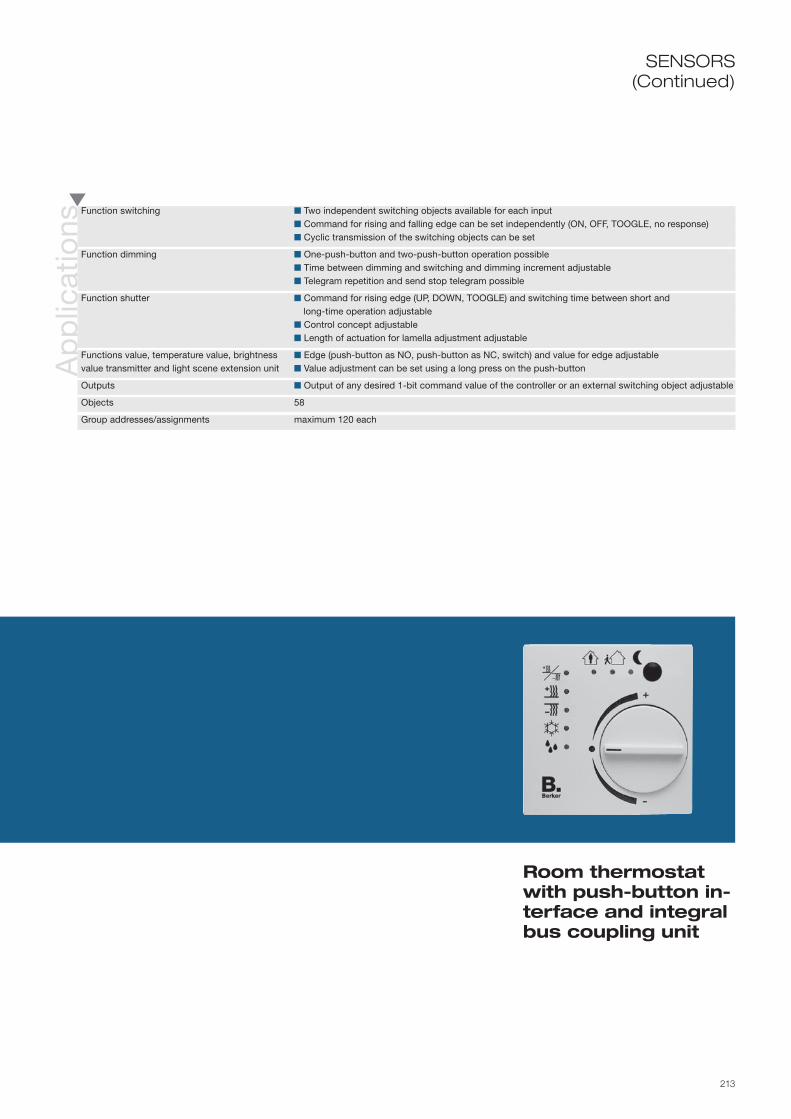
213
SENSORS(Continued)
Ap
plic
atio
ns
Function switching Two independent switching objects available for each input Command for rising and falling edge can be set independently (ON, OFF, TOOGLE, no response) Cyclic transmission of the switching objects can be set
Function dimming One-push-button and two-push-button operation possible Time between dimming and switching and dimming increment adjustable Telegram repetition and send stop telegram possible
Function shutter Command for rising edge (UP, DOWN, TOOGLE) and switching time between short and long-time operation adjustable Control concept adjustable Length of actuation for lamella adjustment adjustable
Functions value, temperature value, brightness Edge (push-button as NO, push-button as NC, switch) and value for edge adjustablevalue transmitter and light scene extension unit Value adjustment can be set using a long press on the push-button
Outputs Output of any desired 1-bit command value of the controller or an external switching object adjustable
Objects 58
Group addresses/assignments maximum 120 each
Room thermostat with push-button in-terface and integral bus coupling unit
214
Info
rmat
ion
Tech
nica
l dat
a Supply via bus line 21– 32 V DC
Inputs Number max. 4 Cable length ≤ 5 m Scanning voltage Continuous signal
Outputs Number max. 2 Cable length ≤ 5 m Output current max. 0.8 mA Output voltage typ. 1.5 V (5 V with open output)
Operation and display elements Programming button under the cover Programming LED red
Connections KNX/EIB Connecting terminal Inputs/outputs 6pole screw terminal
Protection IP 20, EN 60529
Ambient temperature range Operation -5 to +45 °C Storage/transport -40 to +55 °C
Installation e. g. deep flush-mounted box Diameter 60 mm
Mounting orientation as desired
Dimensions (W x H x D) see dimensional drawings
The object room thermostat with push-button interface is designed as a flush-mounted device with an integral bus coupling unit. The thermostat is designed without visible operation and display elements to prevent unauthorised adjustment and sabotage in public areas. Through the optional connection of potential-free switches and push-buttons it is possible to operate all of the room functions in the door area in a cost-optimised manner. The thermostat detects the room temperature and depending on the operating mode and the current setpoint sends a command value to the heating or cooling control on the instabus KNX/EIB. Five operating modes are available (comfort, standby, night, frost/heat protection and dewpoint operation). For the heating and cooling function, the control mode PI control (continuous or switching) or 2-point control (switching) can be selected; two-stage heating and cooling are likewise possible. The integral push-button interface provides four inde-pendent binary inputs for control of lighting, blinds or as value transmitters. Two of these inputs can also be programmed as outputs and thus be used e. g. for activation of LED displays or electronic relays.
Ord
er d
ata MODUL 2
White .......................
Polar white ..............
7544 12 12
7544 12 19
Berker S.1/B.1/B.3/B.7 GLASWhite, glossy ...........
Polar white, glossy ..
Polar white, matt .....
Anthracite, matt .......
Aluminium, matt ......
7544 12 52
7544 12 59
7544 12 89
7544 12 85
7544 12 83
Berker K.1/K.5White .......................
Polar white ..............
Anthracite, matt .......
Aluminium, matt ......
Stainless steel, lacquered ................
7544 12 72
7544 12 79
7544 12 75
7544 12 74
7544 12 73
Berker ARSYSWhite .......................
Polar white ..............
Light bronze, lacquered ................
Stainless steel, lacquered ................
7544 12 42
7544 12 49
7544 12 44
7544 12 43

215
T
SENSORS
ETS search path: Berker >> Heating, air conditioning, ventilation >> Controller >>
Object room thermo-stat with push-button interface and inte-gral bus coupling unit
For individual single room control
Without visible operation and display element for protection against unauthorised operation
With integral bus coupling unit
Programming button and programming LED accessible by pulling off the cover
Ap
plic
atio
ns
Object controller with push-button Temperature detection via internal or external sensor or mixed operation can be setinterface 4gang 705D01 Temperature compensation for sensors and polling time of the external sensor and transmission behaviour adjustable for temperature values Object controller with push-button Operating modes comfort, standby, night, frost/heat protection mode and comfort extension interface 4gang 705D11 (for ETS 3 from version d) can be activated through on-the-spot operation or object Objects for general controller status and per operating mode set Operating mode switching via value (1-byte) or switching (4 x 1-bit) adjustable Operating mode adjustable in preferred position or after reset Operating mode to extend comfort can be activated using presence button or presence object Presence button and setting knob can be programmed to have no functions Operating modes heating/cooling or heating and cooling, each with or without auxiliary step Continuous or switched PI control or two-point control can be set. Control variable objects invertible if required Valve protection function can be set (valve is opened cyclically every 24 hours) Temperature setpoints can be adjusted via software or bus (on the device) Setting range of the temperature setpoints to be specified via software Function as thermostat extension unit for other room thermostats, complete control and display at the thermostat extension unit Room temperature measurement possible at the extension unit Separate window contact object
Push-button interfaceGeneral Description of the previous device
Function switching Description of the previous device
Function dimming Description of the previous device
Function shutter Description of the previous device
Functions value, temperature value, brightnessvalue transmitter and light scene extension unit Description of the previous device
Outputs Description of the previous device
Objects 58
Group addresses/assignments maximum 120 each

216
Info
rmat
ion
Ord
er d
ata
The brightness sensor 3gang is executed as a top hat rail mounted device, and controls switch and/or dim actuators dependent on the ambient light. The ambient light is detected by a supplied external brightness sensor.
Depending on application, the RMD module has multiple software-programmable transmission channels. In addition, by way of a lockout object any combination of transmission channels can be temporarily disabled.
Device colourLight grey ................ 7521 30 06
Tech
nica
l dat
a Supply via bus line 21–32 V DC
Inputs Signal recognition 0–20,000 lux Signal duration Continuous
Operation and display elements Programming button Programming LED Red
Connections RMD module KNX/EIB via connecting terminal Brightness sensor 2 screw-type terminals, max. 100 m cable length
Protection RMD module IP 20, EN 60529 Brightness sensor IP 54, EN 60529
Ambient temperature range RMD module operation -5 to +45 °C Storage/transportation -25 to +70 °C
Mounting RMD module Snap-on to top hat rail Brightness sensor Fixing bracket
Mounting orientation any
Dimensions (WxHxD) RMD module 86 x 35.8 x 60 mm, 2 modules Brightness sensor 86 x 27 x 38 mm

217
Three switching channels
Lockout facility for any combination of the three channels
Separate brightness sensor for interior and exterior (supplied)
Brightness sensor 3gang RMD
ETS search path: Berker >> Physical sensors >> Brightness >>
Ap
plic
atio
ns
Switching, 3 limiting values 0009 Three separately programmable brightness limiting values (setting range: 1 to 10,000 lux) for three switching channels Switching response to infringement of lower and upper limiting values programmable Common setting of the three channels in terms of: – cyclic transmission time – delay – hysteresis Activation/deactivation of any combination of the three channels
Objects 4
Group addresses/assignments maximum of 5 each
Switching, value transmitter, 4 brightness Brightness sensor functions as a light-sensitive light scene moduleareas 0010 Setting range from 1 to 100 lux or 100 to 20,000 lux Definition of four brightness ranges based on three different brightness limiting values Each brightness range is a light scene, comprising three switch objects and one value object Delay for the switch and value telegrams programmable for each brightness range Forced guidance of each scene object
Objects 5
Group addresses/assignments maximum of 5 each
SENSORSN
ote
s
Key1. Brightness sensor2. Brightness sensor connection3. Bus connection4. Programming LED5. Programming button
lx
+–
1
23
45

218
Info
rmat
ion
Ord
er d
ata
Tech
nica
l dat
a Supply via bus line 21–32 V DC
Inputs Signal recognition 0 - 20,000 lux Signal duration Continuous
Operation and display elements Programming button Programming LED Red
Connections KNX/EIB Terminal Inputs Clip-on terminal 0.25 - 0.75 mm2
Single-wire 2 m, non-extendable
Protection Built-in module (decoder) --- Brightness sensor (receiver) IP 20, EN 60529
Ambient temperature range Operation -5 to +45 °C Storage/transportation -25 to +70 °C
Mounting Built-in module (decoder) Fixing holes in housing base Brightness sensor (receiver) Fixing hole dia. 34 mm
Mounting orientation Built-in module (decoder) any Brightness sensor (receiver) Vertical in ceiling
Dimensions (WxHxD) Built-in module (decoder) 274.5 x 42 x 28 mm Brightness sensor (receiver) 26 x 25 x 77.4 mm
The brightness sensor 1gang comprises the KNX/EIB built-in device (decoder) and the separate brightness sensor (receiver).
The decoder evaluates the detected brightness value and, depending on application, controls the lighting over the instabus KNX/EIB with the corresponding dim up or dim down command.
Device colourLight grey ................ 7543 10 01

219
Ap
plic
atio
nsCalibration A00401 Only to calibrate brightness sensor during commissioning Input of current brightness value to determine result of calibration
Objects or group addresses/assignments 2 maximum of 2 each
Constant light regulation A00501 Transmission of 4-bit dimming telegrams to regulate the brightness target value Comparison of current and set-point values by brightness sensor Set-point value shift Transmission of cyclic dimming telegrams to adjust to the desired brightness value
Objects or group addresses/assignments 7 maximum of 15 each
Two position regulation A00601 Transmission of 1-bit telegram for on/off Definition of 2 brightness limiting values for on/off Definition of brightness limiting value as value transmitter (1-byte) Comparison of current value and the two set-point values Transmission of a switching telegram in event of continuous deviation; monitoring of lower limiting
value for switch-on and of upper limiting value for switch-off.
Objects or group addresses/assignments 4 maximum of 15 each
Send lux value A00701 Transmission of 2-byte EIS 5 telegrams
Objects or group addresses/assignments 5 maximum of 18 each
ETS search path: Berker >> Physical sensors >> Brightness >>
Brightness sensor 1gang built-in
Constant brightness control
Limiting value control
Separate brightness sensor for interior (supplied)
No
tes
Key1. Brightness sensor2. Brightness sensor connection3. Programming LED
4. Programming button5. Bus connection6. Intermediate ceiling7. Brightness sensor
Mounting configuration
lx
SENSORS
+–
134
5 2
67

220
Info
rmat
ion
Ord
er d
ata
Tech
nica
l dat
a Supply via bus line 21–32 V DC Power consumption < 150 mW
Measuring range Brightness 0 to 100 klx Sensing angles: horizontal ± 60°, vertical -35 to +65° Temperature -25 to 55 °C
Operation and display elements Programming button Programming LED Red
Terminals KNX/EIB Terminals
Protection IP 54, EN 60529 when mounted vertically with cover
Ambient temperature range Operation -25 to +55 °C Storage/transport -25 to +70 °C
Mode of fixing Surface-mounted on wall Use installation bracket
Mounting orientation vertical
Weight approx. 140 g
Dimensions (W x H x D) 72 x 110 x 54 mm
The sensor is designed as a surface-mounted device, and can detect brightness and temperature values. These values are transmitted to the bus as telegrams, e.g. in order to depict them graphically. The sensor also has four channels with one limit value switch each for linking the values that are used to control switch, dim-mer and shutter actuators.
Also available is a sun protection channel with 3 limit values that can be used to control the height and lamella position of shading systems. This can be employed, for example, for integration into the awning, conservatory and greenhouse controllers.
Device colourWhite ....................... 7549 20 02

221
Brightness and temperature sensor
SENSORS
Sensing ambient brightness and temperature
Activation of switch, dimmer or shutter actuators
Brightness and temperature-dependent switching and valuator device
Several limit switches for brightness, temperature and shading
Constant light control
Surface-mounted device for external mounting
No
tes Selection of mounting location
Please note the following:- Direct sunlight can affect the temperature reading.
- A dirty cover will affect the brightness reading. Whenever possible, select a mounting position where the sensor is not exposed to dirt.
CareTo remove dirt, clean the cover occasionally with a damp cloth.
Key1. Sensor aperture2. Programming LED3. Programming button4. Bus connection
ETS search path: Berker >> Physical sensors >> Brightness/temperature>>
lx T
+–
2
1
3
4
Ap
plic
atio
ns4 x brightness/temperature, 1 x sun shading Transmission of brightness and temperature values cyclically or when changed Comparison value for temperature detection adjustable Function selection for each channel as brightness or temperature sensor or universal channel with AND operation of brightness/temperature Separate teaching object for brightness limit value for each brightness/universal channel Brightness and temperature limit values selectable with fine adjustments within the measurement range Brightness/temperature-dependent switching, priority and value transmitter adjustable for each channel Two objects per channel – first and second telegram can be set separately Sun protection channel with twilight limit value and three brightness limit values Activation/deactivation of the sun shading via twilight limit value Operating modes shutter, roller blind, value transmitter or scene control for sun protection channel
adjustable For each brightness limit value of the sun shading channel, the lamella position, drive height, value or scene is adjustable Blocking of each channel via object
Objects 27
Group addresses/assignments maximum 108 each

222
Info
rmat
ion
Ord
err d
ata
Tech
nica
l dat
a
The binary input 4gang is executed as a top hat rail mounted device. It detects the presence of or change in the 230 V voltage signals at its input terminals (e. g. from conventional switches, auxiliary contacts, door and window contacts) and, depending on the chosen programming, sends telegrams over the instabus KNX/EIB.
The four inputs can be assigned different functions independently of each other. Each input is provided with an LED, which indicates the status of the associated contact. Inputs can be individually locked out.
Supply via bus line 21–32 V DC
Inputs 4 Signal voltage 110 - 230 V AC, ±10 %, 50/60 Hz “0” signal 0 - 70 V AC “1” signal > 90 V AC Signal current approx. 7 mA at 230 V AC per input Signal duration Tmin. = 200 ms at pulse-pause ratio 1:1 Power consumption per channel approx. 1.6 VA at 230 V AC per input Length of input cable max. 100 m (unshielded)
Behaviour on power Bus power failure ---failure/restoration Bus power failure Falling edge detected, software-dependent Bus and mains power failure --- Bus power restoration Software-dependent Mains power restoration Rising edge detected, software-dependent Bus and mains power restoration Software-dependent
Operation and display elements Programming button Programming LED Red 4 status LEDs Yellow
Terminals KNX/EIB Terminals Inputs Terminals with wire protection: 0.75 – 4 mm² solid, 0.75 – 4 mm² fine wire without end cap sleeve
Protection IP 20, EN 60529 Protection class II
Ambient temperature range Operation -5 to +45 °C Storage/transport -25 to +70 °C
Mounting Snap-on to top hat rail
Mounting orientation any
Dimensions (WxHxD) 35 x 90 x 58 mm 2 modules
Device colourLight grey ................ 7521 40 08

223
4
Four independent 230 V AC inputs
Different phases can be connected
Simultaneous application of signal voltage to all inputs
Four status LEDs to indicate input states
Binary input 4gang 230 V AC
SENSORSA
pp
licat
ions
Universal input 705502 Free assignment of the functions switch, dim, shutter, value transmitter to the four 4 inputs Locking out the individual inputs using object Delay on bus power restoration and de-bounce time centrally configurable Behaviour on bus power restoration configurable separately for each input Telegram rate limitation configurable globally for all inputs Free assignment of the functions “pulse counter” and “switching counter” to inputs 1 and 2 (if “pulse
counter”, inputs 3, 4 then reserved for synchronising signal)
Switching Two independent switch objects for each input enabled individually Command independently configurable on rising or falling edge (ON, OFF, TOGGLE, no function) Independent cyclical transmission of the switched object can be selected to be dependent on the
signal edge or dependent on the object value
Dimming Single surface or two-surface operation possible Time between dimmer and switch function and dimming step width configurable Optional telegram repetition and transmission of a stop telegram
Shutter Command configurable on rising edge (UP, DOWN, TOGGLE, no function) Operating concept parameterizable (step and move operation) Slat adjustment time configurable
Value transmitters Function as dimmer value transmitter, light scene retrieval, temperature value transmitter, brightness value transmitter Edge (button as normally-open, button as normally-closed, switches) and value at edge configurabl Values can be set using the button by pressing the button for a long period Light scene extension units with memory function allow the scene to be saved without previously retrieving it
Objects or group addresses/assignments 12 maximum26/maximum 27
ETS search path: Berker >> Inputs >> Binary input, 4gang >>
No
tes
Key1. Status LED2. Programming button3. Programming LED4. Bus connection
IMPORTANTThe reference potential N must be connected separately for each input. Different phases can be con-nected.
+–
E1 N1
E1 E2 E3 E4
E3
L1L2L3N
N3
E2 N2
E4 N4
1
23
4

224
Info
rmat
ion
Ord
er d
ata
The binary input 6gang is executed as a top hat rail mounted device. It detects the presence of or change in the 24 V voltage signals at its input terminals (e.g. from conventional switches, auxiliary contacts, door and window contacts) and, depending on the chosen programming, sends telegrams over the instabus KNX/EIB.
The six inputs can be assigned different functions independently of each other. Each input is provided with an LED, which indicates the status of the associated contact. Inputs can be individually locked out.
Tech
nica
l dat
a Supply via bus line 21–32 V DC
Inputs 6 Signal voltage 8 – 42 V AC/DC, 50/60 Hz “0” signal 0 to 1.8 V AC, -42 to 1.8 V DC “1” signal > 8 V AC/DC Signal current approx. 4 mA at 24 V AC/DC per input Signal duration Tmin. = 200 ms at pulse-pause ratio 1:1 Power consumption per channel approx. 100 mW at 24 V AC/DC per input Length of input cable max. 100 m (unshielded)
Behaviour on power Bus power failure ---failure/restoration Bus power failure Falling edge detected, software-dependent Bus and mains power failure --- Bus power restoration Software-dependent Mains power restoration Rising edge detected, software-dependent Bus and mains power restoration Software-dependent
Operation and display elements Programming button Programming LED red 6 status LEDs yellow
Terminals KNX/EIB Terminals Inputs Terminals with wire protection: 0.75 – 4 mm² solid, 0.75 – 4 mm² fine wire without end cap sleeve
Protection IP 20, EN 60529 Protection class II
Ambient temperature range Operation -5 to +45 °C Storage/transport -25 to +70 °C
Mounting Snap-on to top hat rail
Mounting orientation any
Dimensions (WxHxD) 35 x 90 x 58 mm 2 modules
Device colourLight grey ................ 7521 60 01

225
6
Binary input 6gang 24V AC/DC
ETS search path: Berker >> Inputs >> Binary input, 6gang >>
Six independent 24 V AC/DC inputs
A separate reference potential (GND) for each three inputs
Simultaneous application of signal voltage to all inputs
Six status LEDs to indicate input states
SENSORSA
pp
licat
ions
Universal input 705602 Free assignment of the functions switch, dim, shutter, value transmitter to the four 6 inputs Locking out the individual inputs using object Delay on bus power restoration and de-bounce time centrally configurable Behaviour on bus power restoration configurable separately for each input Telegram rate limitation configurable globally for all inputs Free assignment of the functions “pulse counter” and “switching counter” to inputs 1 and 2 (if “pulse
counter”, inputs 3, 4 then reserved for synchronising signal)
Switching Two independent switch objects for each input enabled individually Command independently configurable on rising or falling edge (ON, OFF, TOGGLE, no function) Independent cyclical transmission of the switched object can be selected to be dependent on the
signal edge or dependent on the object value
Dimming Single surface or two-surface operation possible Time between dimmer and switch function and dimming step width configurable Optional telegram repetition and transmission of a stop telegram
Shutter Command configurable on rising edge (UP, DOWN, TOGGLE, no function) Operating concept parameterizable (step and move operation) Slat adjustment time configurable
Value transmitters Function as dimmer value transmitter, light scene retrieval, temperature value transmitter, brightness value transmitter Edge (button as normally-open, button as normally-closed, switches) and value at edge configurable Values can be set using the button by pressing the button for a long period Light scene extension units with memory function allow the scene to be saved without previously retrieving it
Objects; group addresses/assignments 18; maximum 26/maximum 27
No
tes
Key1. Status LED2. Programming button3. Programming LED4. Bus connection
IMPORTANTInputs 1–3 and 4–6 each have a common reference potential.
24 V AC/DC
+–
GND
E1 E2 1-3E3
E5
E1 E2 E3 E4 E5 E6
E4 E6 4-6
1
23
4

226
Info
rmat
ion
Ord
er d
ata
The binary input 8gang is executed as a top hat rail mounted device. It detects the presence of or change in the 230 V voltage signals at its input terminals (e. g. from conventional switches, auxiliary contacts, door and window contacts) and, depending on the chosen programming, sends telegrams over the instabus KNX/EIB.
The eight inputs can be assigned different functions independently of each other. Each input is provided with an LED, which indicates the status of the associated contact. Inputs can be individually locked out.
Device colourLight grey ................ 7521 80 01
Tech
nica
l dat
a Supply via bus line 21–32 V DC
Inputs 8 Signal voltage 110 – 230 V AC, ±10 %, 50/60 Hz “0” signal 0 – 70 V AC “1” signal > 90 V AC Signal current approx. 7 mA at 230 V AC per input Signal duration Tmin. = 200 ms at pulse-pause ratio 1:1 Power consumption per channel approx. 1.6 VA at 230 V AC per input Length of input cable max. 100 m (unshielded)
Behaviour on power Bus power failure ---failure/restoration Bus power failure Falling edge detected, software-dependent Bus and mains power failure --- Bus power restoration Software-dependent Mains power restoration Rising edge detected, software-dependent Bus and mains power restoration Software-dependent
Operation and display elements Programming button Programming LED red 8 status LEDs yellow
Terminals KNX/EIB Terminals Inputs Terminals with wire protection: 0.75 – 4 mm² solid, 0.75 – 4 mm² fine wire without end cap sleeve
Protection IP 20, EN 60529 Protection class II
Ambient temperature range Operation -5 to +45 °C Storage/transport -25 to +70 °C
Mounting Snap-on to top hat rail
Mounting orientation any
Dimensions (WxHxD) 70 x 90 x 58 mm 4 modules

227
8
SENSORSA
pp
licat
ions
Universal input 705402 Free assignment of the functions switch, dim, shutter, value transmitter to the four 4 inputs Locking out the individual inputs using object Delay on bus power restoration and de-bounce time centrally configurable Behaviour on bus power restoration configurable separately for each input Telegram rate limitation configurable globally for all inputs Free assignment of the functions “pulse counter” and “switching counter” to inputs 1 and 2 (if “pulse
counter”, inputs 3, 4 then reserved for synchronising signal)
Switching Two independent switch objects for each input enabled individually Command independently configurable on rising or falling edge (ON, OFF, TOGGLE, no function) Independent cyclical transmission of the switched object can be selected to be dependent on the
signal edge or dependent on the object value
Dimming Single surface or two-surface operation possible Time between dimmer and switch function and dimming step width configurable Optional telegram repetition and transmission of a stop telegram
Shutter Command configurable on rising edge (UP, DOWN, TOGGLE, no function) Operating concept parameterizable (step and move operation) Slat adjustment time configurable
Value transmitters Function as dimmer value transmitter, light scene retrieval, temperature value transmitter, brightness value transmitter Edge (button as normally-open, button as normally-closed, switches) and value at edge configurable Values can be set using the button by pressing the button for a long period Light scene extension units with memory function allow the scene to be saved without previously retrieving it
Objects; group addresses/assignments 24; maximum 26/maximum 27
No
tes
Key1. Status LED2. Programming button3. Programming LED4. Bus connection
IMPORTANTThe reference potential N must be connected separately for each input.Different phases can be connected.
Eight independent 230 V AC inputs
Different phases can be connected
Simultaneous application of signal voltage to all inputs
Eight status LEDs to indicate input states
Binary input 8gang 230 V
ETS search path: Berker >> Input >> Binary input, 8gang >>
L1
+–
L2L3N
E1 N1 E2 N2 E3 N3 E4 N4
E5 N5 E6 N6 E7 N7 E8 N8
E1 E2 E3 E4 E5 E6 E7 E8 1
23
4

228
Info
rmat
ion
Ord
er d
ata Device colour
Light grey ................ 7564 20 01
Tech
nica
l dat
a Supply via bus line 21–32 V DC Power consumption typ. 150 mW
Inputs Number max. 2 Cable length ≤ 5 m Scanning voltage Continuous signal
Outputs Number max. 2 Cable length ≤ 5 m Output current max. 0.8 mA Parallel circuit in total 1.5 mA Output voltage typ. 1.5 V (5 V with open output)
Response to power Bus power failure no response (outputs switch off)failure/restoration Mains power failure --- Bus and mains power failure --- Bus power restoration programmable for inputs and outputs Mains power restoration --- Bus and mains power restoration ---
Operation and display elements Programming button Programming LED Red
Connections KNX/EIB Terminals Inputs/outputs Pre-assembled connecting cables
Protection IP 20, EN 60529 Protection class III
Ambient temperature range Operation -5 to +45 °C Storage/transport -25 to +70 °C
Assembly e. g. deep flush-mounted box diameter 60 mm
Mounting orientation any
Dimensions (WxHxD) 43 x 28.5 x 15.5 mm
The universal interface 2gang comfort is designed as a flush-mounted device and has two independent channels. This means that the push-button interface can read in two push-button/switching statuses potential-free at a common reference potential and transit the appropriate telegrams to the instabus.
If programmed appropriately, the channels can also operate as independent outputs and control LEDs as status LEDs for example. To raise the output current (cf. technical data), these channels can also be connected in parallel if they have the same parameters.
The outputs are short-circuit-proof, and protected against overload and polarity reversal.

229
Universal interface 2gang comfort
SENSORSA
pp
licat
ions
2 inputs, 2 outputs 705801General Free assignment of the switch, dim, shutter and value transmitter functions to the max. two inputs Free assignment of the “Pulse meter” and “Switching Meter” functions to inputs 1 and 2 Blocking object for blocking individual inputs (polarity of the blocking object is programmable) Delay in event of bus power restoration and de-bounce time centrally programmable Response to bus power restoration programmable separately for each input Telegram rate limitation programmable globally for all inputs
Switching function Two independent switching objects available for every input Command in event of rising or falling flank independently programmable (ON, OFF, TOGGLE, no function) Cyclical transmission of the switching objects programmable
Dimming function Single surface and two-surface operation possible Time between dimmer and switch function and dimming step width programmable Telegram repetition and Stop telegram transmission possible
Shutter function Command in event of rising edge (UP, DOWN, TOGGLE) and switchover time between step and move operation programmable Operating concept programmable Operation period for lamella shutter adjustment programmable
Value, temperature and brightness value Edge (button as normally-open, button as normally-closed, switches) and value at edge programmabletransmitter function and light scene extension Value can be changed by pressing and holding the push-button
Outputs Independent outputs programmable as NO (normally open) or NC (normally closed) contacts Preferred location programmable on restoration of bus voltage One switching status report and one additional function possible for each output Programmable additional functions:
logic operation function with three logical parameters, lock-out / forced positioning function On and/or Off delay or time switch function programmable for each output separately Flashing output signal programmable (flashing frequency in three stages)
Objects 24
Group addresses/assignments 26/27
ETS search path: Berker >> Input >> Universal >>
Assembly possible in a deep flush-mounted box behind installation switches
2 potential-free inputs
Channels can be used as outputs
Input and output functions can be combined
Short-circuit-proof
Reverse polarity protection
Continued on next double page
8

230
Info
rmat
ion

231
SENSORS(Continued)
Universal interface 2gang comfort
No
tes IMPORTANT
Only connect potential-free switches and push-buttons.
HardwareTo avoid electromagnetic inter-ference, the cables of the inputs should not be laid parallel to live cables carrying mains power.
The connection of 230 V signals or other external voltages to the inputs is not permitted.
The voltage potentials of the con-necting cables for the contacts and the LED are not electrically isolated from the bus voltage.
Connection diagrams/terminal assignmentThe colour of the cable for the reference potential is grey.
Key1. Reference potential (grey)2. Channels 1 and 23. Programming LED4. Programming button5. Bus connection6. Connecting cables
Use as 2 x inputs
1 x input and 1 x output
1
54 3
2
6
E1 (green)
(grey)
E2 (yellow)
A1 (green)
(grey)
E2 (yellow)
232
Info
rmat
ion
Ord
er d
ata Device colour
Light grey ................ 7564 40 01
Tech
nica
l dat
a Supply via bus line 21–32 V DC Power consumption typ. 150 mW
Inputs Number max. 4 Cable length ≤ 5 m Scanning voltage Continuous signal
Outputs Number max. 2 Cable length ≤ 5 m Output current max. 0.8 mA Parallel circuit in total 1.5 mA Output voltage typ. 1.5 V (5 V with open output)
Response to power Bus power failure no response (outputs switch off)failure/restoration Mains power failure --- Bus and mains power failure --- Bus power restoration programmable for inputs and outputs Mains power restoration --- Bus and mains power restoration ---
Operation and display elements Programming button Programming LED Red
Connections KNX/EIB Terminals Inputs/outputs Pre-assembled connecting cables
Protection IP 20, EN 60529 Protection class III
Ambient temperature range Operation -5 to +45 °C Storage/transport -25 to +70 °C
Assembly e. g. deep flush-mounted box diameter 60 mm
Mounting orientation any
Dimensions (WxHxD) 43 x 28.5 x 15.5 mm
The universal interface 4gang comfort is designed as a flush-mounted device and has four independent channels. This means that the push-button interface can read in up to four push-button / switching statuses potential-free at a common reference potential and transit the appropriate telegrams to the instabus.
If programmed appropriately, channels 1 and 2 can also operate as independent outputs and activate LEDs as status LEDs for example. To raise the output current (cf. technical data), these channels can also be con-nected in parallel if they have the same parameters.
The outputs are short-circuit-proof, and protected against overload and polarity reversal.

233
Universal interface 4gang comfort
SENSORSA
pp
licat
ions
4 inputs, 2 outputs 705701General Free assignment of the switch, dim, shutter and value transmitter functions to the max. four inputs Free assignment of the “Pulse meter” and “Switching Meter” functions to inputs 1 and 2 Blocking object for blocking individual inputs (polarity of the blocking object is programmable) Delay in event of bus power restoration and de-bounce time centrally programmable Response to bus power restoration programmable separately for each input Telegram rate limitation programmable globally for all inputs
Switching function Two independent switching objects available for every input Command in event of rising or falling flank independently programmable (ON, OFF, TOGGLE, no function) Cyclical transmission of the switching objects programmable
Dimming function Single surface and two-surface operation possible Time between dimmer and switch function and dimming step width programmable Telegram repetition and Stop telegram transmission possible
Shutter function Command in event of rising edge (UP, DOWN, TOGGLE) and switchover time between step and move operation programmable Operating concept programmable Operation period for lamella shutter adjustment programmable
Value, temperature and brightness Edge (button as normally-open, button as normally-closed, switches) and value at edge programmabletransmitter function and light scene extension Value can be changed by pressing and holding the push-button
Outputs Independent outputs programmable as NO (normally open) or NC (normally closed) contacts Preferred location programmable on restoration of bus voltage One switching status report and one additional function possible for each output Programmable additional functions:
logic operation function with three logical parameters, lock-out / forced positioning function On and/or Off delay or time switch function programmable for each output separately Flashing output signal programmable (flashing frequency in three stages)
Objects 24
Group addresses/assignments 26/27
ETS search path: Berker >> Input >> Universal >>
Assembly possible in a deep flush-mounted box behind installation switches
Four potential-free inputs
Channels 1 and 2 can be used as outputs
Input and output functions can be combined
Short-circuit-proof
Reverse polarity protection
Continued on next double page
8

234
Info
rmat
ion

235
Universal interface 4gang comfort
SENSORS(Continued)
IMPORTANTOnly connect potential-free switches and push-buttons.
HardwareTo avoid electromagnetic inter-ference, the cables of the inputs should not be laid parallel to live cables carrying mains power.
The connection of 230 V signals or other external voltages to the inputs is not permitted.
The voltage potentials of the con-necting cables for the contacts and the LED are not electrically isolated from the bus voltage.
Connection diagrams/terminal assignmentThe colour of the cable for the reference potential is grey.
Key1. Reference potential (grey)2. Channels 1 to 43. Programming LED4. Programming button5. Bus connection6. Connecting cables
Used as 4 x inputs
2 x inputs and 2 x outputs
E1 (green)
(grey)
E2 (red)
E3 (yellow)
E4 (pink)
A1 (green)
(grey)
A2 (red)
E3 (yellow)
E4 (pink)
1
54 3
2
6

236
Info
rmat
ion
Ord
er d
ata Device colour
Black ....................... 7564 80 01
Tech
nica
l dat
a Supply via bus line 21–32 V DC
Inputs Number max. 8/4 (depending on application) Cable length ≥ 10 m Scanning voltage 20 V pulses, 2 ms long, cyclic every 60 ms
Outputs Number max. 8/4 (depending on application) Cable length 10 m Output current 0.8 mA (constant) each output
Response to power Bus power failure No responsefailure/restoration Mains power failure --- Bus power restoration All object values of the outputs are cleared Mains power restoration --- Bus and mains power restoration ---
Operation and display elements Programming button Programming LED Red
Connections KNX/EIB Terminal Inputs/outputs 2 x 5-pin screw-terminal connector blocks
Protection IP 20, EN 60529
Ambient temperature range Operation -5 to +45 °C Storage/transportation -25 to +70 °C
Mounting e. g. deep UP socket Diameter 60 mm
Mounting orientation any
Dimensions (WxHxD) 44 x 48 x 32 mm
The universal interface comfort 8gang is executed as a flush-mounted device. It has eight channels which, depending on the loaded application, operate all as inputs or outputs or as a combination of the two (four inputs/four outputs).
The device can operate up to eight LEDs, for example, by way of its independent outputs, or poll up to eight potential-free push-buttons via its inputs and send telegrams over the instabus KNX/EIB accordingly. The outputs are short-circuit-proof, and protected against overload and polarity reversal.
To avoid electromagnetic interference, the cables of the inputs should not be laid parallel to live cables carrying mains power.
Interference voltages must not be connected to the inputs.

237
Universal interface 8gang comfortflush-mounted
SENSORSA
pp
licat
ions
General features Free assignment of the Switching/Toggle, Dimming, Shutter, Value transmitter/light scene extension, Forced guidance and Control functions
Switching/toggle function Command programmable on rising or falling edge (ON, OFF, TOGGLE, no function) Cyclic transmission
Dimming function Single or two-area (one push-button or two push-buttons) operation programmable Switchover time between dimmer and switch function and dimming step width programmable Telegram repetition and transmission of a stop telegram
Shutter function Touch function (UP, DOWN) and switchover time between step and move operation programmable Operation period for shutter lamella adjustment programmable
Value transmitter/light scene extension function Switch between 1-byte value transmitter or light scene retrieval with/without memory function programmable Value adjustment by “long button press” programmable
Forced guidance function Command programmable on rising and falling edge
4 inputs 4 outputs, 8 outputs 704001 Maximum of 8 outputs usable for status/operating indication via LED
Objects or group addresses/assignments 18 maximum of 26 each
8 inputs 704101 Eight potential-free binary inputs 2 user levels programmable 4-digit level switch code freely selectable
Objects or group addresses/assignments 18 maximum of 26 each
ETS search path: Berker >> Input >> Binary input universal >>
Inputs potential-free
Optionally programmable
– Eight inputs
– Four inputs and 4 outputs
– Eight outputs
Short-circuit-proof
Reverse polarity protection
No
tes
8
8 inputs 4 inputs and 4 outputs 8 outputs
IMPORTANTConnect only potential-free switches and push-buttons!
IMPORTANTConnect only potential-free switches and push-buttons. Pay attention to reference potentials of the inputs and outputs!

238
Info
rmat
ion
Ord
er d
ata
The time switch (weekly) 2gang is a top hat rail mounted device with integral bus coupling unit. The connec-tion to the KNX/EIB is made via a terminal.
The timer offers 36 switching times, programmable by customized block formation on one day, several days or every day of the week.
Ex factory the device is preprogrammed with the current time and for automatic Summer/Winter time switch-ing (according to Central European practice). If a different time configuration, or no time switching, is required, the setup can be reprogrammed as set out in the operating instructions.
Device colourLight grey ................ 7521 20 06
Tech
nica
l dat
a Supply via bus line 21–32 V DC
Timer Channels 2 Memory locations 36 Automatic program Day and week program Special program Interruption of automatic program from 1 to 99 days Shortest switching interval 1 minute Switching accuracy 1 second Summer/Winter time switching automatic Accuracy < 1s per day at 20 °C Reserve > 6 years with indicator Manual operation Temporary/permanent manual operation
Display LCD display
Operation and display elements 7 jog buttons Time setting, program input and 2 hand switches Programming button Programming LED Red
Connections KNX/EIB Terminal
Protection IP 20, EN 60529
Ambient temperature range Operation -5 to +45 °C Storage/transportation -25 to +70 °C
Mounting on top hat rail 35 mm, EN 50022
Mounting orientation any
Dimensions (WxHxD) 35.8 x 45 x 60 mm 2 modules

239
Two independent channels
Switching, value and forced guidance telegrams
Time preprogrammed
Automatic Summer/Winter time switching
Transmission of up to four telegrams per channel
Storage of 36 switching times
Time switch (weekly) 2gang
SENSORSA
pp
licat
ions
Switching, value transmitter, forced guidance Selection of telegram type for the two channels as follows: – Switching telegram (1-bit) – Forced guidance telegram (2-bit) – Value telegram (8-bit) – Cyclic transmission Implementation of one scene per channel with up to four different telegram types In this way, different types of actuators or actuator groups (switch/dim/shutter actuators) can be operated at one switching time. “Lock object” (telegram suppression) programmable for each channel
Objects 9
Group addresses/assignments maximum of 11 each
ETS search path: Berker >> Timer >> Time switch >>
No
tes
2
t
Key1. Bus connection2. Display3. User buttons4. Programming button5. Programming LED
+–1
2
3
54

240
Info
rmat
ion
Ord
er d
ata
The time switch (annual) 4gang is a top hat rail mounted device. The connection to the instabus KNX/EIB is made via a terminal.
The time switch offers 324 switching times for selectable day, week and date commands, pulse commands, priority switching times, as well as one-off configurations for public holidays and vacation periods. For each channel, in addition to the standard week program nine further week programs with priority levels P1 to P9 and time-limited continuous operation can be programmed. The period covered by a priority program is defined by input of a start and end date.
The OBELISK memory card is programmed by means of the programming set. After programming, the memory card is slotted into the time switch (annual) and all relevant data are then transferred.
Ex factory the device is preprogrammed with the current time and for automatic Summer/Winter time switching.
Device colourLight grey ................ 7521 40 07
Tech
nica
l dat
a Supply via bus line 21–32 V DC
Timer Channels 4 Memory locations 324 Automatic program Day, week and year program Special program 9 priority programs Public holiday programs Shortest switching interval 1 minute Switching accuracy 1 second Summer/Winter time switching automatic Accuracy < 1 sec/day Reserve > 1.5 years with indication Manual operation Temporary/permanent manual operation
Display LCD display
Operation and display elements 15 jog buttons Time setting, program input and 2 hand switches Programming button Programming LED Red
Connections KNX/EIB Terminal
Protection IP 20, EN 60529
Ambient temperature range Operation -5 to +45 °C Storage/transportation -25 to +70 °C
Mounting on top hat rail 35 mm, EN 50022
Mounting orientation any
Dimensions (WxHxD) 105 x 45 x 60 mm 6 modules
AccessoriesProgramming setfor OBELISK ............
OBELISKmemory card ...........
7590 00 48
7590 00 49

241
Four independent channels
Switching, value and forced guidance telegrams
Summer/Winter time switching
324 switching times
Nine priority programs
Random functions
Setting of switching times by programming set possible
Transfer to time switch by OBELISK memory card
Time switch (annual) 4gang
SENSORSA
pp
licat
ions
Switching, value transmitter, forced guidance Selection of telegram type for the four channels as follows: – Switching telegram (1-bit) – Forced guidance telegram (2-bit) – Value telegram (8-bit) – Cyclic transmission With channel 4 implementation of a scene with up to four different telegram types possible In this way, different types of actuators or actuator groups (switch/dim/shutter actuators) can be operated at one switching time.
Objects 8
Group addresses/assignments maximum of 10 each
Switching, value transmitter, time and date transmission see description of the next product
Switching, value transmitter, time and date reception see description of the next product
ETS search path: Berker >> Timer >> Time switch >>
No
tes
Key1. Programming LED2. Programming button3. Emergency power battery4. User buttons5. Display6. OBELISK slot7. Bus connection
IMPORTANTThe applications of the time switch (annual) 4gang DCF (next product 7521 40 06) are used!
4
t
Programming set for OBELISK
L1N
+–
21
354
67
OBELISK memory card

242
Info
rmat
ion
Ord
er d
ata
The time switch (annual) 4gang is a top hat rail mounted device. The connection to the instabus KNX/EIB is made via a terminal.
The device switch is prepared for connection of the DCF receiver.
The time switch offers 324 switching times for selectable day, week and date commands, pulse commands, priority switching times, as well as one-off configurations for public holidays and vacation periods. For each channel, in addition to the standard week program nine further week programs with priority levels P1 to P9 and time-limited continuous operation can be programmed. The period covered by a priority program is defined by input of a start and end date.
The OBELISK memory card is programmed by means of the programming set. After programming, the memory card is slotted into the time switch (annual) and all relevant data are then transferred.
The device is preprogrammed with the current time and for automatic Summer/Winter time switching.
Device colourLight grey ................ 7521 40 06
Tech
nica
l dat
a Supply via bus line 21–32 V DC
Timer Channels 4 Memory locations 324 Automatic program Day, week and year program Special program 9 priority programs Public holiday programs Shortest switching interval 1 minute Switching accuracy 1 second Summer/Winter time switching automatic Accuracy < 1 sec/day or radio-controlled Reserve > 1.5 years with indication Manual operation Temporary/permanent manual operation
Display LCD display
Inputs DCF receiver
Operation and display elements 15 jog buttons Time setting, program input and 2 hand switches Programming button Programming LED Red
Connections KNX/EIB Terminal
Protection IP 20, EN 60529
Ambient temperature range Operation -5 to +45 °C Storage/transportation -25 to +70 °C
Mounting on top hat rail 35 mm, EN 50022
Mounting orientation any
Dimensions (WxHxD) 105 x 86 x 60 mm 6 modules
AccessoriesDCF receiver ...........
Programming set for OBELISK .................
OBELISK memory card .........................
7590 00 47
7590 00 48
7590 00 49
Continued on next double page

243
Four independent channels
Switching, value and forced guidance telegrams
Summer/Winter time switching
324 non-erasable switching times
Nine priority programs
Random functions
Connection for DCF receiver
Setting of switching times by programming set possible
Transfer to time switch by OBELISK memory card
Time switch (annual) 4gang DCF
SENSORSA
pp
licat
ions
Switching, value transmitter, forced guidance Selection of telegram type for the four channels as follows: – Switching telegram (1-bit) – Forced guidance telegram (2-bit) – Value telegram (8-bit) – Cyclic transmission With channel 4 implementation of a scene with up to four different telegram types possible In this way, different types of actuators or actuator groups (switch/dim/shutter actuators) can be operated at one switching time.
Objects 8
Group addresses/assignments maximum of 10 each
Switching, value transmitter, Selection of telegram type for the four channels as follows: time and date transmission – Switching telegram (1-bit) – Forced guidance telegram (2-bit)
ETS search path: Berker >> Timer >> Time switch >>
No
tes
Continued on next double page
4
t
DCF receiver Programming set for OBELISK OBELISK memory card
244
Info
rmat
ion
Tech
nica
l dat
a DCF receiver
Supply via time switch (annual) 4gang DCF
Display Function LED Flashing once per second
Outputs DCF 77 Connecting cable e.g. NYM 3 x 1.5 mm2, max. 100 m
Reception range 1500 km around Frankfurt/Main, Germany
Protection IP 54, EN 60529
Ambient temperature range Operation -20 to +70 °C Storage/transportation -25 to +70 °C
Mounting Surface-mounted Wall bracket, screw fixing (supplied)
Mounting orientation Arrow pointing toward Frankfurt/Main, Germany
Dimensions (WxHxD) 98 x 64 x 34 mm
Mount the DCF receiver with the supplied mounting bracket at a location which permits it to be simply aligned toward Frankfurt/Main, Germany.
In selection of the mounting location, avoid close proximity to TV sets, power packs, radio signal transmitters or large metallic objects.
Connect the DCF receiver’s lead to the screw terminals provided (see diagram at right, item 7). When you activate the year timer, the reception LED assigned to the DCF receiver begins to flash. Align the DCF receiver so it flashes at a frequency of once per second.

245
SENSORS(Continued)
Ap
plic
atio
ns
Switching, value transmitter, time and date – Dimmer/value telegram (8-bit) transmission (continued) – Cyclic transmission – Transmission of date and time per minute, per hour, per day or on request
Objects 7
Group addresses/assignments maximum of 8 each
Switching, value transmitter, temperature, Selection of telegram type for the four channels as follows:time and date reception – Switching telegram (1-bit) – Forced guidance telegram (2-bit) – Dimmer/value telegram (8-bit) – Temperature telegram (16-bit) – Any telegram in EIS 5 format (16-bit) – Cyclic transmission – Synchronization/setting of time by reception of time and date telegram
Objects 6
Group addresses/assignments maximum of 8 each
No
tes
Time switch (annual) 4gang DCF
Key1. Programming LED2. Programming button3. Emergency power battery4. User buttons5. Display6. OBELISK slot7. DCF receiver connection8. Bus connection
L1N
+–
21
354
678

246
Info
rmat
ion
Ord
er d
ata Device colour
Light grey ................ 7591 00 02
Tech
nica
l dat
a
The time transmitter RMD is designed as a top hat rail mounted device.
The time transmitter has a quartz movement and transmits the time and date to the bus. Either the time can be set via the bus or it can be synchronised with the DCF signal. The time transmitter has an automatic summer/winter time change-over that can also be switched off. This way the time transmitter is also suitable for use as a clock for shade systems with sun level calculation.
Supply via bus line 21– 32 V DC
Input DCF receivers Max. cable length 100 m
Clock Internal quartz time basis Time deviation 1 s/d without DCF Power reserve 10 years (lithium battery)
Operation and display elements Programming button Programming LED red DCF status LED red
Connections KNX/EIB Connecting terminal Input Screw terminal with wire protection
Protection IP 20, EN 60529
Ambient temperature range Operation -10 to +50 °C Storage/transport -25 to +70 °C
Installation Snap onto top hat rail
Mounting orientation as desired
Dimensions (W x H x D) 36 x 90 x 66 mm 2 modules
AccessoriesDCF receivers .......... 7590 00 47
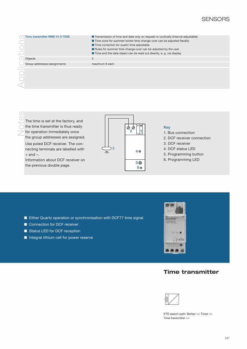
247
Either Quartz operation or synchronisation with DCF77 time signal
Connection for DCF receiver
Status LED for DCF reception
Integral lithium cell for power reserve
ETS search path: Berker >> Timer >> Time transmitter >>
Time transmitter
Ap
plic
atio
nsN
ote
sSENSORS
Time transmitter RMD V1.0 705B Transmission of time and date only on request or cyclically (interval adjustable) Time zone for summer/ winter time change-over can be adjusted flexibly Time correction for quartz time adjustable Rules for summer time change-over can be adjusted by the user Time and the date object can be read out directly, e. g. via display
Objects 3
Group addresses /assignments maximum 8 each
Key1. Bus connection2. DCF receiver connection3. DCF receiver4. DCF status LED5. Programming button6. Programming LED
The time is set at the factory, and the time transmitter is thus ready for operation immediately once the group addresses are assigned.
Use poled DCF receiver. The con-necting terminals are labelled with + and –.Information about DCF receiver on the previous double page.
2 1
5
34
6

248
Info
rmat
ion
Ord
er d
ata
Tech
nica
l dat
a
The analogue input 4gang is designed as a top hat rail mounted device and is used to acquire and forward up to four analogue sensor signals. The analogue input can evaluate both voltage and current signals. The current inputs with the measurement range 4–20mA can be monitored for wire break.
Sensor signals are converted into 1-byte or 2-byte value telegrams. Two limit values can be set per sensor; these can trigger measured-value dependent events, such as control of shutters and blinds, switching exterior lighting, etc. By means of external objects it is possible to adapt all of the limit values while operation continues, e. g. via KNX/EIB devices such as information display or MT 701 plus or MT 701 ct. Operation of the analogue input requires a 24 V auxiliary voltage. External analogue sensors are supplied with voltage via the short-circuit and overload protected outputs.
The lateral interface can be used to connect an analogue input module for another 4 sensors, which are likewise adjusted via the software of the basic unit.
Supply via bus line 21– 32 V DC
Auxiliary voltage 24 V AC ± 10 % SELV Current input max. 250 mA
Inputs Sensor inputs 4 Current 0–20 mA, 4–20 mA Voltage 0–1 V, 0–10 V Input resistance Voltage measurement approx. 18 kOhm Current measurement approx. 100 ohm
Outputs Supply outputs 2 Rated voltage 24 V AC ±10 % Maximum current 100 mA DC total
Behaviour in the event of power failure Bus voltage failure no communication with KNX/EIB Supply voltage failure no communication with KNX/EIB, no supply for the sensors
Behaviour in the event of power return Bus voltage no communication with KNX/EIB, no supply for the sensors Supply voltage no communication with KNX/EIB Bus and supply voltage Transmission of the measurement and limit values as per initialisation parameters of the application
Operation and display elements Programming key Programming LED Red Status LED Red/green
Connections KNX/EIB Connecting terminal Inputs 0.5–4 mm² single/finely stranded without conductor sleeve, 0.5–2.5 mm² finely stranded with conductor sleeve Module connection 6pole system plug for analogue input module
Protection IP 20, EN 60529
Ambient temperature range Operation -5 to +45 °C Storage/transport -25 to +70 °C
Dimensions (W x H x D) 72 x 90 x 58 mm 4 modules
Device colourLight grey ................ 7541 40 04
AccessoriesAnalogue input module ....................
Power supply 24 V AC ...................
7542 40 04
7591 00 01

249
4
Four freely adjustable sensor inputs
Four additional sensor inputs possible using analogue input module
Conversion of analogue measurement data into 1-byte and 2-byte values (EIS 5/6)
System interface for connection of an analogue input module
24 V DC output for supplying connected sensors
Analogue input 4gang
SENSORSA
pp
licat
ions
Analogue input 4gang V2 B00A01Analogue inputs Connectable sensor type can be adjusted for the integral analogue inputs: 0–1 V; 0–10 V; 0–20 mA; 4–20 mA Transmission behaviour for measured values adjustable 1 or 2-byte can be chosen as transmission format Two limit values with hysteresis can be set per input Two external limit values per input can be selected for adjustment via EIB devices in ongoing operation Wire break monitoring can be set for 4–20 mA sensors Transmission of an alarm bit can be set
Modules One analogue input module with four additional inputs can be selected: Programming options are the same as the basic unit
Objects 50
Group addresses/assignments max. 200 each
No
tes
Key1. Analogue input module
connection 2. Bus connection 3. Programming button 4. Programming LED 5. Status LED6. Active sensor
Terminals+US: Supply for external
sensorsGND: Reference potential for
+US and inputsE1…E4: Measured value inputsAC 24 V: External supply
voltage2
134
56

250
Info
rmat
ion
Ord
er d
ata
Tech
nica
l dat
a
The analogue input module is designed as a top hat rail mounted device. It is an inexpensive way to expand the analogue input 4gang or the weather station comfort to include four connections for four additional sensors. No separate application is available for the device; programming is carried out via the software of the basic unit.
For operation the analogue input requires a 24 V auxiliary voltage that is made available either directly from the 24V AC power supply or indirectly via the 24 V AC terminals of the basic unit.
Auxiliary voltage 24 V AC ± 10 % SELV Current input max. 250 mA
Inputs Sensor inputs 4 Current 0–20 mA, 4–20 mA Voltage 0–1 V, 0–10 V Input resistance Voltage measurement approx. 18 kOhm Current measurement approx. 100 ohm
Outputs Supply outputs 2 Rated voltage 24 V AC ±10 % Maximum current 100 mA DC total
Operation and display elements Status LED Red/green
Connections inputs 0.5 –4 mm² single/finely stranded without conductor sleeve, 0.5–2.5 mm² finely stranded with conductor sleeve Module connection 6pole system plug for analogue input module
Protection IP 20, EN 60529
Ambient temperature range Operation -5 to +45 °C Storage/transport -25 to +70 °C
Dimensions (W x H x D) 72 x 90 x 58 mm 4 modules
Device colourLight grey ................ 7542 40 04

251
No
tes
Four additional sensor inputs for analogue input 4gang or weather station comfort
Link to basic unit via 6pole system interface
Status LED for indicating readiness for operation
24 V DC output for supplying connected sensors
Analogue input module 4gang
SENSORS
Key1. Analogue input 4gang2. Status LED 3. System plug, 6pole4. Active sensor
Connection of an analogue input module is exclusively by means of the 6pole system plug. Only one analogue input module can be connected per basic unit.The connections +US and GND of the analogue input module may not be connected to the corresponding connections of another device, e. g. of the analogue input. This may result in accidental ground energisation.Sensors that are connected to the inputs of the analogue input module may not be supplied by the analogue input, and vice versa. Exchange on an analogue input module e. g. in the event of a defect can be carried out in ongo-ing operation (isolate module from voltage!). After the exchange the analogue input carries out a reset after approx. 25 seconds. This re-initialises and places in the original state all inputs and outputs of the analogue input and the connected module.
Terminals+US: Supply for external
sensors
GND: Reference potential for +US and inputs
E1…E4: Measured value inputsAC 24 V: Ext. supply voltage
21
3
4

252
Info
rmat
ion
Tech
nica
l dat
a
The KNX weather station is designed as a surface-mounted device, and detects wind speed, precipitation twilight, temperature and brightness in 3 directions. It is designed especially for use in homes. The main area of use is the automatic, weather-dependent control of shading systems.
The evaluation of the data themselves, especially the limit value processing, takes part already in the weather station. Logic gates are available for linking of the limit values and monitoring functions. Blocking elements can be used to block individual functions locally. To increase functional reliability, the weather station monitors some of its own important functions and automatically reports the corresponding errors to the bus via indica-tor objects.
The function is protected against frost and condensation to -20 °C by a built-in heating system. The weather station requires an external 24 V power supply for the heating and the precipitation sensor.
Supply via bus line 21 – 32 V DC Power consumption typical 450 mW
Auxiliary voltage 24 V AC/DC SELV Power consumption typical 7.5 W
Wind measurement Range 0 to 40 m/s Accuracy 2 m/s
Precipitation measurement Range yes/no (binary) Sensitivity fine drizzle
Brightness measurement 3 sensors each offset by 90° Range 1 to 110 klx Spectral range 700 to 1050 nm Accuracy 10% (of final value)
Twilight measurement Range 0 to 674 lux Spectral range 700 to 1050 nm Accuracy 10% (of final value)
Temperature Range -20 to +55 °C Accuracy ±1 K (at wind speeds > 0.5 m /s)
Operation and display element programming button Programming LED red
Connections KNX/EIB Connection terminal Auxiliary voltage Connecting terminal yellow/white
Protection class IP 44 acc. to DIN EN 60 529 in position of normal use
Ambient temperature range Operation -20 to +55 °C Storage/transport -40 to +70 °C
Installation type Surface-mounted wall/mast mounting
Mounting orientation vertical
Dimensions (W x H x D) 88 x 170 x 204 mm
Ord
er d
ata Device colour
Aluminium ............... 7549 00 01AccessoriesPower supply 24 V AC........
Mast adapter ...........
Corner mounting piece .......................
7591 00 01
0154
0149 09

253
Detection of the ambient brightness and temperature
Compact device for outdoor installation with integrated bus coupling unit
With integrated wind, precipitation, twilight, temperature and brightness sensors
Directional brightness detection via three sensors
Rotatable sensor head
Processing of the measurement data in the weather station
Ap
plic
atio
ns
Weather station B00901 Output of the meas. values for temperature, wind, twilight, 3 x brightness (3 directions) as 16-bit valuesWeather station B00911 (for ETS 3 from version d) Two limit values with adjustable hysteresis for each sensor (except for precipitation) adjustable or
specifiable externally as 8-bit values or 16-bit values Teaching function for adopting the current 2-byte measured value as a limit value Parameterisable input and output delay for all limit value objects 6 Logic gates (AND, AND with return, OR, exclusive OR, NAND, NOR) with up to 4 inputs for external
and internal 1-bit values 4 Blocking elements for blocking of functions or for manual operation Output of all values when there is a value change and cyclically Cascading of weather stations via the logic functions Monitoring of heating voltage and wind signal adjustable
Objects 89
Group addresses/assignments maximum 200 each
info
rmat
ion
Weather station
Wetter7
Legend1. Terminal box with KNX/EIB con-
necting terminals and auxiliary voltage
2. Bracket arm3. Thermal wind sensor 4. Temperature sensor 5. Twilight and brightness sensor 26. Brightness sensor 17. Sensor head, can be turned 90°,
translucent8. Precipitation sensor
Selecting the installation locationPlease note:- The device must not be affected
by obstacles or shading on any side.
- The weather station should also be accessible later for mainte-nance/cleaning purposes.
CareTo remove dirt deposits, clean the sensor head from time to time with a moist cloth.
SENSORS
ETS search path: Berker >> Physical sensors >> Weather station >>
7
8
12
5 6
4 3

254
Info
rmat
ion
Ord
er d
ata Device colour
Light grey ................ 7541 40 03AccessoriesAnalogue input module ....................
Combi weather sensor surface-mounted ..................
Power supply 24 V AC ...................
7542 40 04
7590 00 57
7591 00 01
Tech
nica
l dat
a
The weather station 4gang comfort is designed as a top hat rail mounted device. It makes it possible to con-nect four freely configurable sensors for detecting weather data and to acquire, process and forward their measured values. The measured values are converted into 1-byte or 2-byte value telegrams. Two limit values can be set per sensor; these can trigger measured-value dependent events, such as control of shutters, switching exterior lighting, etc. By means of external objects it is possible to adapt all of the limit values while operation continues, e. g. via EIB devices such as Info display. The weather station is programmed using a clearly-organised software plug-in; configuration is made easier by the ability to select pre-configured sensors of the system. Operation requires a 24 V auxiliary voltage. External sensors are supplied with voltage via the short-circuit and overload protected outputs. An analogue input module for an additional four sensors can be connected via interfaces. It is also possible to connect a combi weather sensor with an integral DCF77 receiver. These devices are likewise programmed using the software of the basic unit.
Supply via bus line 21– 32 V DC
Auxiliary voltage 24 V AC ± 10 % SELV Current input max. 250 mA
Inputs Sensor inputs 4 Current 0–20 mA, 4–20 mA Voltage 0–1 V, 0–10 V Input resistance Voltage measurement approx. 18 kOhm Current measurement approx. 100 ohm
Outputs Supply outputs 2 Rated voltage 24 V AC ±10 % Maximum current 100 mA DC total
Behaviour in the event of power failure Bus voltage failure no communication with KNX/EIB Supply voltage failure no communication with KNX/EIB, no supply for the sensors
Behaviour in the event of power return Bus voltage no communication with KNX/EIB, no supply for the sensors Supply voltage no communication with KNX/EIB Bus and supply voltage Transmission of the measurement and limit values as per initialisation parameters of the application
Operation and display elements Programming key Programming LED red Status LED red/green
Connections KNX/EIB Connecting terminal Inputs 0.5–4 mm² single/finely stranded without conductor sleeve, 0.5–2.5 mm² finely stranded with conductor sleeve Module connection 6pole system plug for analogue input module Sensor connection 4pole system plug for combi weather sensor
Protection IP 20, EN 60529
Ambient temperature range Operation -5 to +45 °C Storage/transport -25 to +70 °C
Dimensions (W x H x D) 72 x 90 x 58 mm 4 modules

255
4
Weather station 4gang comfort
SENSORS
ETS search paths: Berker >> Entry >> Analogue input, 4gang >>Berker >> Physical sensors >> Weather station >>
Four freely adjustable sensor inputs
Four additional sensor inputs possible using analogue input module
System interface for connection of an analogue input module
Connection for combi weather sensor surface-mounted
24 V DC output for supplying connected sensors
SENSORSA
pp
licat
ions
Weather station comfort B00602Analogue inputs Connectable sensor type can be adjusted for the integral analogue inputs: 0 –1, 0–10 V; 0 –20, 4–20 mA Selection of the pre-configured system sensors for the analogue inputs: wind sensor, brightness sensor, twilight sensor, temperature sensor, rain sensor, humidity sensor, air pressure sensor. Transmission behaviour for measured values adjustable Transmission of an alarm bit can be set 1 or 2-byte can be chosen as transmission format for measured values Two limit values with hysteresis can be set per input (other than rain sensor) Two external limit values per input can be selected for adjustment via EIB devices in ongoing operation Wire break monitoring can be set for 4 –20 mA sensors
Blocking modules 16 blocking modules available One input, output and blocking object per blocking module Per input and output object format switching 1-bit, value 1-byte and value 2-byte can be set
Logic controller Number of logic gates freely selectable, but limited by the max. number of objects (200) Logic "AND", "OR", "exclusive OR" can be set Number of inputs selectable per logic gate (max. 8 inputs) For output object, switch on delay, switch off delay and cyclic transmission are adjustable
Modules One analogue input module with four additional inputs can be selected: Programming options as for the basic unit One combi sensor can be selected: Programming options see combi sensor Common selection of analogue input module and combi sensor possible
Objects 200
Group addresses/assignments max. 200 each
No
tes
Key1. Analogue input module connection 2. Combi weather sensor connection3. Bus connection 4. Programming button 5. Programming LED 6. Status LED7. Active sensor
Terminals+US: Supply for external
sensorsGND: Reference potential for
+US and inputsE1…E4: Measured value inputsAC 24 V: External supply voltage 3
145
67
2

256
Info
rmat
ion
Ord
er d
ata Device colour
Light grey ................ 7591 00 01Combination withWeather station 4gang comfort .........
Analogue input 4gang ......................
7541 40 03
7541 40 04
Tech
nica
l dat
a
The power supply is designed as a top hat rail mounted device. It generates the operating voltage for the applicable KNX/EIB devices such as the weather station 4gang comfort RMD or analogue input 4gang RMD.
For convenient connection the device has two internally connected 24 V outputs. In addition, the heating voltage for sensors such as a combi weather sensor surface-mounted or rain sensor surface-mounted can be made available using the device.
The voltage supply is protected against overload by a thermostatic switch.
Supply Primary voltage 230 V AC ±10 %, 50/60 Hz
Output Supply for KNX/EIB devices 2 connecting terminals Voltage 24 V AC ±10 % Output current max. 1 A Switch-on time 100 % Short-circuit protection Thermostatic switch
Connections Inputs/supply outputs Screw terminals 0.5 – 4 mm2, single-core Screw terminals 0.34–4 mm2, finely stranded (without conductor sleeve) Screw terminals 0.14 –2.5 mm2, finely stranded (with conductor sleeve)
Protection IP 20, EN 60529 DIN 40050
Ambient temperature range Operation -5 °C to +45 °C Storage/transport -25 °C to +70 °C
Humidity Environment/storage/transport max. 93 % relative humidity (moisture condensation not permissible)
Installation on top hat rail 35 mm EN 50022
Mounting orientation as desired
Dimensions (W x H x D) 72 x 90 x 70 mm 4 modules

257
Power supply 24 V AC
SENSORS
Output current up to 1 A
Two 24 V connecting terminals for convenient connection
Thermostatic switch for overload/overheating protection
No
tes
Key1. Power supply RMD 2. Connection 230 V3. Power supply 24 V 4. Output 24 V
TerminalsAC 230 V ~: Mains voltage AC 24 V: Supply voltage
InstallationThe output terminals are designed in pairs. The terminals with the same potential are connected internally (labelled with dot).
In the event of overload or short-circuit the thermostatic switch switches the device off if excessively heated.The device starts again auto-matically after the short-circuit is rectified and it has cooled down.
5. Example: Analogue input 4gang RMD
2
1
3 4
5

258
Info
rmat
ion
Ord
er d
ata
Tech
nica
l dat
a
Device colourBlack ....................... 7590 00 57
AccessoriesWeather station 4gang comfort .........
Power supply 24 V AC .....................
7541 40 03
7591 00 01
The combi weather sensor combines seven sensors in a single device. It is used to measure wind speed, precipitation, brightness and twilight, and is connected directly to the weather station 4gang comfort. Combining different sensors in a single device reduces the amount of installation work. Additionally, the combi weather station has a DCF77 receiver that not only serves as a clock for the bus, but also enables integration of the time signal into an expanded shading control. Through the use of three brightness sensors oriented to the east, south, and west and connected to the weather station it is possible to control the shading systems for different sides of the building depending on the compass direction.
Operation of the combi weather sensor requires a 24 V supply voltage, e. g. like that provided by the 24 V AC power supply.
The additional heating of the combi sensor protects the electronics against condensation.
Supply voltage AC/DC 24 V ±15 %, 50/60 Hz Current input max. 600 mA Power consumption (sensors and heater) max. 14.4 W
Sensor measurement range Wind speed approx. 1 –40 m/s Precipitation yes/no Twilight approx. 0–674 lux Brightness approx. 1–110 klx, per compass direction east, south, west
Operation and display elements Reed contact Activation of the acoustic DCF signal Adjusting screw Orientation of the DCF antenna
Connecting cable 10 m, pre-assembled LiYCY, 6 x 0.25 mm² max. 50 m
Protection IP 55, EN 60529 in position of normal use
Ambient temperature range Operation -40 to +60 °C, ice-free Storage/transport -40 to +60 °C
Mounting orientation vertical Wind wheel up
Dimensions (Ø x H) 130 x 200 mm

259
Ap
plic
atio
nsN
ote
s
Combi weather sensor
SENSORS
DCF77 receiver
Buzzer for quality indication of the DCF77 signal
PTC heater element for winter operation
Mounting bracket and Nirost clamp for fixing to a mast
Pre-assembled connecting cable
Weather station comfort B00601 (expanded options with combi sensor) Monitoring of the link to the combi sensor and testing the signals for conclusiveness In conjunction with DCF77 reception automatic shading of up to four sides of the building with tracking of the lamellae depending on the position of the sun Transmission behaviour of date and time and sun position can be set Entry of the geographical position for time-dependent calculation of the position of the sun Entry of the orientation of the side of the building for automatic, expanded shading control Transmission of the lamella position as an angle or in percent can be set Object for external adaptation of the basic brightness and opening angle to the sun
Key1. Wind wheel 2. Twilight sensor3. Fixing bracket with screw holes 4. Brightness sensor west
Brightness sensor east Brightness sensor south
5. Precipitation sensor (north)
InstallationFor interference-free reception of the DCF77 signal, maintain a dis-tance of 3 m from other electrical devices.So that the brightness sensors can detect the state of the sun's course unambiguously, the combi sensor should be aligned with a compass in such a way that the precipitation window points to the north. The housing should be as free as possible from dust deposits so as not to distort the measurements. During operation, rain will keep the housing surfaces largely clean.
The heating of the combi sensor pro-tects the electronics against conden-sation in the specified temperature range. It does not protect against icing of the housing or moving parts.
4
1
5
2
3
4 4

260
Info
rmat
ion
Ord
er d
ata
The WS wind speed sensor is deployed in conjunction with the weather station 4gang or the analogue input.
It registers and evaluates the wind speed.
The rotation speed, recorded by way of a reed contact, is converted by an electronic circuit into an analogue output signal from 0 to 10 V. The optional heating transformer permits trouble-free operation in case of frost.
The necessary supply voltage is provided by the analogue input or the weather station. The 24 V AC RMD power supply can provide the heating voltage for sensors such as the wind sensor surface-mounted or the rain sensor surface-mounted.
Connection to external systems is possible.
Tech
nica
l dat
a Measuring range linear 0.7 to 40 m/s
Electrical output 0 to 10 V min. 1.5 K Ω load
Supply Voltage 24 V DC (18 to 32 V DC) Current consumption approx. 12 mA (without heater) Heater 24 V DC/AC, PTC element (80 °C)
Loading short-time max 60 m/s
Lead 3 m LiYY 6 x 0.25 mm2
Cable length max. 100 m Follow installation instructions
Weight 300 g
Protection IP 65, EN 60529
Ambient temperature range Operation -25 to +60 °C Storage/transportation -25 to +70 °C
Fixing method Wall or mast mounted Mounting bracket (supplied)
Mounting orientation vertical
Dimensions Overall height: 160 mm Wind vane diameter: 124 mm
Device colourWhite ....................... 7590 00 50
AccessoriesMast adapter ...........
Power supply 24 V AC ...................
7590 00 46
7591 00 01

261
Wind speed sensor
SENSORSN
ote
s
Registering and evaluation of wind speed
Generation of analogue signals
Non-frost-sensitive opertion with optional WS heating transformer
Selection of mounting locationDo not mount the wind sensor close to transmitters (e. g. private mobile radio).
To avoid distortion of measured values, make sure the sensor is correctly orientated (e. g. not sheltered from the wind).
WiringDo not lay sensor cables parallel to live or load-carrying cables.
To avoid electromagnetic interference, maintain a clearance of a few centi-metres from the cables.
Terminal assignmentWhite: GroundBrown: Operating voltage +24 V DCGreen: Output 0–10 VYellow: GroundGrey/pink: Heater 24 V AC/DC
Power supply 24 V AC

262
Info
rmat
ion
Ord
er d
ata
Tech
nica
l dat
a Electrical output 0 V dry, 10 V rain min. 1 kΩ load
Supply Voltage 24 V DC (15 to 30 V DC) Current consumption approx. 10 mA (without heater) Heater 24 V DC/AC, max 4.5 W
Lead 3 m LiYY 5 x 0.25 mm2
Cable length max. 100 m Follow installation instructions
Weight 300 g
Protection IP 65, EN 60529
Ambient temperature range Operation -30 to +70 °C Storage/transportation -25 to +70 °C
Fixing method Wall or mast mounted Mounting bracket (supplied)
Mounting orientation approx. 45°
Dimensions (WxHxD) 60 x 82 x 17 mm
The WS rain sensor is deployed in conjunction with the weather station 4gang or the analogue input.
It registers and evaluates the precipitation.
The conductivity of the rain water is evaluated by means of a meander-shaped sensor and converted by an electronic circuit into an analogue output signal from 0 to 10 V. The optional heating transformer permits the end of the precipitation to be detected more quickly and prevents ice forming on the surface of the sensor. An additional voltage of 24 V AC or DC is required to heat the rain sensor.
The necessary supply voltage is provided by the analogue input or the weather station. The 24 V AC RMD power supply can provide the heating voltage for sensors such as the wind sensor surface-mounted or the rain sensor surface-mounted.
Connection to external systems is possible.
Device colourGrey ......................... 7590 00 52
AccessoriesMast adapter ...........
Power supply 24 V AC ...................
7590 00 46
7591 00 01

263
Rain sensor
SENSORSN
ote
s
Registering and evaluation of precipitation
Generation of analogue signals
Connection of optional heater
Power supply 24 V AC
Selection of mounting locationDo not mount the rain sensor close to transmitters (e. g. private mobile radio).
The mounting location must ensure direct precipitation impact (not installed underneath roof overhangs).
CareThe sensor must be cleaned regularly with a mild cleaning agent, and so should be mounted at an easily accessible location.
WiringDo not lay sensor cables parallel to live or load-carrying cables. To avoid electromagnetic interference, main-tain a clearance of a few centimetres from the cables.
Terminal assignmentWhite: GroundBrown: Operating voltage +24 V DCGreen: Output 0–10 VYellow/ grey: Heater 24 V

264
Info
rmat
ion
Ord
er d
ata
Tech
nica
l dat
a Measuring range 0 to 60 klx linear
Electrical output 0 to 10 V (min. 1 kΩ load) Short-circuit-proof
Supply Voltage 24 V DC (15 to 30 V DC) Current consumption approx. 5 mA
Lead via PG7 gland 3 x 0.25 mm2
Cable length max. 100 m Follow installation instructions !
Weight approx. 200 g
Protection IP 65, EN 60529
Ambient temperature range Operation -30 to +70 °C Storage/transportation -25 to +70 °C
Fixing method Wall or mast mounted
Mounting orientation any
Dimensions (WxHxD) 58 x 64 x 35 mm
The WS brightness sensor is deployed in conjunction with the weather station 4gang or the analogue input. It registers and evaluates the brightness.
The registered brightness is converted by an electronic circuit into a linear, analogue output signal from 0 to 10 V. To prevent damp forming in the housing, the device is fitted with a pressure compensation element (climate control diaphragm).
The required supply voltage for the brightness sensor is delivered by the weather station 4gang or the analogue input.
Connection to third-party systems is possible.
Device colourGrey ......................... 7590 00 53
AccessoriesMast adapter ........... 7590 00 46

265
Brightness sensor
SENSORSN
ote
s
Registering and evaluation of ambient light
Generation of analogue signals
Climate control diaphragm
Selection of mounting locationDo not mount the brightness sensor close to transmitters (e. g. private mobile radio). Pay attention to possible changes in ambient conditions (house shadow, change in level of foliage, etc.).
To avoid distortion of measured values, make sure the sensor is correctly aligned (e. g. East, South, West). Do not mount it within the range of influence of lamps.
WiringDo not lay sensor cables parallel to live or load-carrying cables. To avoid electromagnetic interfe-rence, maintain a clearance of a few centimetres from the cables.
CareThe sensor must be cleaned regularly with a mild cleaning agent, and so should be mounted at an easily accessible location.
Terminal assignment1. Output 0–10 V2. Ground3. Operating voltage 24 V DC
1
32
Mast adapter

266
Info
rmat
ion
Ord
er d
ata
Tech
nica
l dat
a Measuring range -30 to +70 °C linear
Electrical output 0 to 10 V (min. 1 kΩ load) Short-circuit-proof
Supply Voltage 24 V DC (15 to 30 V DC) Current consumption approx. 3 mA
Lead via PG7 gland 3 x 0.25 mm2
Cable length max. 100 m Follow installation instructions !
Weight approx. 200 g
Protection IP 65, EN 60529
Ambient temperature range Operation -30 to +70 °C Storage/transportation -25 to +70 °C
Fixing method Wall or mast mounted
Mounting orientation any
Dimensions (WxHxD) 58 x 64 x 35 mm
The WS temperature sensor is deployed in conjunction with the weather station 4gang or the analogue input.
It registers and evaluates the temperature.
To prevent damp forming in the housing, the device is fitted with a pressure compensation element (climate control diaphragm). The registered temperature is converted by an electronic circuit into an analogue output signal from 0 to 10 V.
The required supply voltage is delivered by the weather station 4gang or the analogue input.
Connection to third-party systems is possible.
Device colourGrey ......................... 7590 00 54
AccessoriesMast adapter ........... 7590 00 46

267
Temperature sensor
SENSORSN
ote
s
Registering and evaluation of outside temperature
Generation of analogue signals
Pressure compensation element
Selection of mounting locationDo not mount the temperature sensor close to transmitters (e. g. private mobile radio).
To prevent distortion of measured values, make sure the sensor is mounted correctly (e. g. not in direct sunlight, not within the range of heaters).
WiringDo not lay sensor cables parallel to live or load-carrying cables.
To avoid electromagnetic interfer-ence, maintain a clearance of a few centimetres from the cables.
Terminal assignment1. Output 0–10 V2. Ground3. Operating voltage 24 V DC
1
32
Mast adapter

268
Info
rmat
ion
Ord
er d
ata
Tech
nica
l dat
a Measuring range 0 to 255 lux linear
Electrical output 0 to 10 V (min. 1 kΩ load) Short-circuit-proof
Supply Voltage 24 V DC (15 to 30 V DC) Current consumption approx. 5 mA
Lead via PG7 gland 3 x 0.25 mm2
Cable length max. 100 m Follow installation instructions
Weight approx. 200 g
Protection IP 65, EN 60529
Ambient temperature range Operation -30 to +70 °C Storage/transportation -25 to +70 °C
Fixing method Wall or mast mounted
Mounting orientation any
Dimensions (WxHxD) 58 x 64 x 35 mm
The WS twilight sensor is deployed in conjunction with the weather station 4gang or the analogue input. It registers and evaluates the brightness.
To prevent damp forming in the housing, the device is fitted with a pressure compensation element (climate control diaphragm). The registered brightness is converted by an electronic circuit into a linear, analogue output signal from 0 to 10 V.
The required supply voltage for the brightness sensor is delivered by the weather station 4gang or the analogue input.
Connection to third-party systems is possible.
Device colourGrey ......................... 7590 00 55
AccessoriesMast adapter ........... 7590 00 46

269
Twilight sensor
SENSORSN
ote
s
Registering and evaluation of ambient light
Generation of analogue signals
Climate control diaphragm
Selection of mounting locationDo not mount the brightness sensor close to transmitters (e. g. private mobile radio).
Pay attention to possible changes in ambient conditions (house shadow, change in level of foliage, etc.).
To prevent distortion of measured values, make sure the sensor is correctly aligned (toward the North, not in direct sunlight).
Do not mount it within the range of influence of lamps.
WiringDo not lay sensor cables parallel to live or load-carrying cables.To avoid electromagnetic inter-ference, maintain a clearance of a few centimetres from the cables.
CareThe sensor must be cleaned regularly with a mild cleaning agent, and so should be mounted at an easily accessible location.
Terminal assignment1. Output 0–10 V2. Ground3. Operating voltage 24 V DC
1
32
Mast adapter

270
Info
rmat
ion
Ord
er d
ata
Tech
nica
l dat
a
The sensor insert is installed in a flush-mounted box and contains a terminal block for connection of wired sensors (e.g. PT-100 temperature sensors).
The sensor is covered by a central plate with slots for air circulation. Mounting is completed with a frame, intermediate ring and central plates for the chosen switch range.
Connections Three-pin terminal block Plug-in terminals up to 1.5 mm2
Protection IP 20, EN 60529
Ambient temperature range Storage/transport -25 to +70 °C
Mounting in flush-mounted box to DIN 49073 Ø 60 mm
Mounting orientation any
Dimensions (W x H x D) 71 x 71 x 30 mm Installation depth 30 mm
Design With support ring..... 7594 10 01
Berker S.1/B.1/B.3/B.7 GLASCentral plate- White, glossy ........- Polar white, glossy .- Polar white, matt ...- Anthracite, matt ....- Aluminium, matt ....
Intermediate ring- White, glossy ........- Polar white, glossy .- Polar white, matt ...- Anthracite, matt ....- Aluminium, matt ....
Berker K.1/K.5Central plate- White .....................- Polar white ............- Stainless steel........
Intermediate ring- White .....................- Polar white ............- Anthracite, matt ....- Aluminium, matt ....- Stainless steel, lacquered ...............
7594 04 027594 04 097594 04 03
1108 70 021108 70 091108 70 061108 70 24
1108 70 04
7594 04 027594 04 097594 04 897594 04 857594 04 83
1109 89 821109 89 891109 19 091109 16 061109 14 04
MODUL 2Central plate- White .....................- Polar white ............
Intermediate ring- White .....................- Polar white ............
7594 04 027594 04 09
1109 021109 09

271
No
tes
MountingThe cover is provided by the cen-tral plate for the sensor unit.
IMPORTANTThe central plate should be used only with an intermediate ring.
Sensor insert
Connection of wired sensors
Protection of sensors by covering with a central plate
Central plate with slots for air circulation
Cover with frame, intermediate ring and central plate for the various switch ranges
SENSORS
Central plate
Intermediate ring
Berker ARSYSCentral plate- White .....................- Polar white ............- Light bronze, lacquered ...............- Stainless steel, lacquered ...............Intermediate ring- White .....................- Polar white ............- Light bronze, lacquered ...............- Stainless steel, lacquered ...............
7594 04 027594 04 09
7594 04 04
7594 04 03
1108 00 021108 00 69
1108 90 11
1108 90 04

272
Info
rmat
ion
Ord
er d
ata
Tech
nica
l dat
a
The radio receiver is executed as a surface-mounted device, and links radio bus transmitters to the instabus KNX/EIB.
In the process, received radio telegrams are converted into corresponding KNX/EIB telegrams.
Up to 50 channels can be assigned a total of 100 memory locations for buttons (e. g. hand-held transmitter buttons) and devices (e. g. standard monitors).
The data transfer is unidirectional.
Supply via bus line 21–32 V DC 9 V block battery Only required for programming
Radio signal input Number of channels 50 Radio memory locations 100 Transmission medium Radio Reception frequency 433.42 Hz Modulation ASK
Response to power Bus power failure -failure/restoration Bus power restoration -
Operation and display elements Channel indicator Two-digit seven-segment display 2 channel selector buttons Acknowledgement button Programming button Programming LED Red Operation LED Green
Connections KNX/EIB Terminal Battery Battery connection clip
Protection IP 20, EN 60529
Ambient temperature range Operation -5 to +45 °C Storage/transportation -25 to +70 °C
Mounting Fixing holes in housing base
Mounting orientation any
Dimensions (WxHxD) 110 x 94 x 38 mm
Device colourWhite ....................... 7563 00 04
Hand-held radio transmitterComfort ...................
Mini .........................
2766
2769

273
SENSORSA
pp
licat
ions
Radio receiver C00102 The application includes the following channel functions:
Switching Function of upper/left and lower/right buttons programmable
Toggle Alternating transmission of ON and OFF telegrams per button
Dimming Dimming step width programmable Send telegram repetition and stop telegram
Shutter control Touch function (UP, DOWN) and time between step and move operation programmable Louvered shutter adjustment time (time in which a move command is terminated by releasing the button) programmable
Value transmitter Value (0 to 255) of upper/left and lower/right buttons programmable
Light scene extension Light scene number (1 to 8) of upper/left and lower/right buttons programmable Memory function possible
Light scene Retrieve and store up to 5 light scenes each with 8 outputs via buttons or extension Object types: switch (1-bit) or dimmer value (1-byte) configurable per output
Movement controller Send 1-bit switching or 1-byte value telegrams dependent on preset twilight value Telegram configurable at beginning and end of a detection Transmission delay at end of detection and lockout time configurable
Universal transmitter as switch Send ON/OFF telegrams according to the received universal transmitter telegrams
Objects 109
Group addresses/assignments maximum of 113 each
ETS search path: Berker >> Communication >> Radio >>
Radio receiver
No
tes Key
1. Operation LEDs2. Channel selector button3. Programming button4. Programming LED5. Acknowledgement button6. Channel indicator7. Battery terminal8. Bus connection
EIB
FUNK
+–
1
32
45
678+–
1
32
45
678
Hand-held radio transmitter comfort

274

275
Switch actuators 276–301Dim actuators 302–311Control units 312–313Shutter actuators 314–339Analogue actuators 340–343Other actuators 344–361
ACTUATORS
The actuators comprise the bus coupling unit, power module and application program. They are selected specific to the application and actuated with sensors.
The information for processing first passes over the bus to the bus coupling unit. The bus coupling unit sends and receives data, delivers power for the electronics,
saves key data for its own physical address, one or more group addresses and the application program with parameters.
The power module and the application program define the function of the actuator.
Dim
. dra
win
gs
Glo
ssar
yTr
aini
ng
Ser
vice
Oth
erco
mp
one
nts
Lo
gic
mo
dul
esV
isu
al r
epre
-se
ntat
ion
sA
ctu
ato
rs

276
Info
rmat
ion
Ord
er d
ata
Tech
nica
l dat
a
The switch actuator 2gang is designed as a rail mounted device. It receives KNX/EIB telegrams and carries out appropriate switching functions depending on the setting using its mutually independent relay contacts. Each switching output has a separate bistable switching relay, so that switching states can also be secured in the event of a bus voltage failure.
The manual selection switches on the front of the device can be used to switch the relays on and off by means of manual actuation in parallel with KNX/EIB, even without bus voltage or in the unprogrammed state. The relay position is not detected via the bus, however.
When the device is configured and commissioned with the ETS 3.0d or newer versions, the advantages of the new actuator generation, such as shorter download times and parameter configuration are fully usable. A separate product database is available for older ETS2/3 versions.
The switch actuator is supplied completely by the KNX/EIB and therefore does not require any additional external power supply.
Device colourLight grey ................ 7531 20 08
Supply via bus line 21–32 V DC
Outputs 2 NO contacts potential-free μ contacts, bistable Rated voltage 230/400 V AC: 50/60 Hz DC: 24 V Switching current 230 V AC: 16 A/AC-1; 10 A /AC-3 400 V AC: 10 A/AC-1; 6 A /AC-3 DC: 16 A/24 V Making current max. 400 A, 150 µs; 200 A, 600 µs Min. switching current 100 mA (for 24 V)
Behaviour in the event of voltage Bus voltage failure software-dependentfailure/return Bus voltage return software-dependent
Breaking capacity Ohmic load 3600 W Incandescent lamps/HV halogen lamps 2500 W LV halogen Conventional transformers: 1200 VA Tronic transformers: 1500 W Fluorescent lamps T5/T8 uncompensated: 2500 W parallel-compensated: 1300 W, 140 µF Duo circuit: 2300 W, 140 µF Mercury vapour lamps uncompensated: 2000 W parallel-compensated: 2000 W, 140 µF
Operation and display elements 2 manual selection switches Relay ON/OFF Programming button Programming LED red
Connections KNX/EIB Connection terminal
Outputs: Screw terminals 0.2 – 4 mm² / 2 x 0.2 – 2.5 mm² single stranded 0.75 – 4 mm² finely stranded without cond. sleeve 0.5 – 2.5 mm² finely stranded with cond. sleeve
Protection class IP 20, EN 60529
Ambient temperature range Operation or storage/transport -5 to +45 °C / -25 to +70 °C
Mounting on top hat rail 35 mm, EN 50022
Mounting orientation as desired preferably output terminals up
Dimensions (W x H x D) 72 x 90 x 70 mm 4 modules

277
Ap
plic
atio
nsin
form
atio
n
Two independent outputs
Outputs can be set as NO or NC
Potential-free bistable NO contacts 16 A
Manual selection switch with status indication for each output
Switch actuator 2gang 16 A, NO, manual, status
ACTUATORS
Switching RM, VK, ZF 209006 Independent switching of the two outputs NO or NC operation can be setSwitching RM, VK, ZF 209016 Central switching function with group feedback(for ETS 3 from version d) Switching feedback (only in bus operation): Active (when changed or cyclically) or passive (object can
be read out) feedback function can be set Logical linking function ("AND", "OR", "AND with return") for each output Blocking function adjustable for each channel – alternatively forced setting function for each output Time functions (switch-on, switch-off delay, stair light function - also with pre-warning function) Can be included in light scenes, up to eight internal scenes can be set Operating hours meter can be activated for each output Input monitoring for cyclic updating with safety position Responses in the event of bus voltage failure and return and after an ETS programming process can
be set for each channel
Objects 26
Group addresses/assignments maximum 254/maximum 255
ETS search path: Berker >> Output >> Binary output, 2gang >>
Legend1. manual selection switch/status indication2. Bus connection3. Programming button4. Programming LED
NOTESuitable for switching different external phase conductors.
The relay outputs of the switch actuator switch with a small time delay when adjusted via a central telegram.
The connection of mains voltage and SELV/PELV electric circuits to a switch actuator is not permitted.
The connection of three-phase motors is not permitted.
2
1
2
4 3

278
Info
rmat
ion
Ord
er d
ata
Tech
nica
l dat
a
The switch actuator 4gang is designed as a top hat rail mounted device. It receives KNX/EIB telegrams and carries out appropriate switching functions depending on the setting using its mutually independent relay contacts. Each switching output has a separate bistable switching relay, so that switching states can also be secured in the event of a bus voltage failure.
The manual selection switches on the front of the device can be used to switch the relays on and off by means of manual actuation in parallel with KNX/EIB, even without bus voltage or in the unprogrammed state. The relay position in not detected via a bus, however. When the device is configured and commissioned with the ETS3.0d or newer versions, the advantages of the new actuator generation, such as shorter download times and parameter configuration are fully usable. A separate product database is available for older ETS2/3 versions. The switch actuator is supplied completely by the KNX/EIB and therefore does not require any additional external power supply.
Device colourLight grey ................ 7531 40 15
Supply via bus line 21– 32 V DCOutputs 4 NO contacts potential-free µ contacts, bistable Rated voltage 230/400 V AC: 50/60 Hz DC: 24 V Switching current 230 V AC: 16 A/AC-1; 10 A/AC-3 400 V AC: 10 A/AC-1; 6 A/AC-3 DC: 16 A/24 V Making current max. 400 A, 150 µs; 200 A, 600 µs Min. switching current 100 mA (at 24 V)
Behaviour in the event of power Bus voltage failure software-dependentfailure/restore Bus voltage restore software-dependent
Breaking capacity Ohmic load 3600 W Incandescent lamps/HV halogen lamps 2500 W LV halogen Conventional transformers: 1200 VA Tronic transformers: 1500 W Fluorescent lamps T5/T8 uncompensated: 2500 W parallel-compensated: 1300 W, 140 µF Duo circuit: 2300 W, 140 µF Mercury vapour lamps uncompensated: 2000 W parallel compensated: 2000 W, 140 µF
Operation and display elements 4 manual selection switches ON/OFF relay Programming button
Programming LED Red
Connections KNX/EIB Connecting terminal
Outputs: Screw terminals 0.2 –4 mm² or 2 x 0.2–2.5 mm² single-core 0.75–4 mm² finely stranded without conductor, 0.5 –2.5 mm² finely stranded with conductor sleeve
Protection class IP 20, EN 60529
Ambient temperature range Operation and storage/transport -5 to +45 °C and -25 to +70 °C
Installation on top hat rail 35 mm, EN 50022
Mounting orientation as desired preferably output terminals up
Dimensions (W x H x D) 72 x 90 x 70 mm 4 modules

279
Ap
plic
atio
nsN
ote
s
Four independent outputs
Outputs can be set as NO or NC
Potential-free bistable NO contacts 16 A
Manual selection switch with status indication for each output
Switch actuator 4gang 16 A NO manual status
ACTUATORS
Switching RS, LO, TF 209001 Independent switching of the four outputs NO or NC operation can be setSwitching RS, LO, TF 209011 Central switching function with group feedback(for ETS 3 from version d) Switching feedback (only in bus operation): Active (when changed or cyclically) or passive (object can
be read out) feedback function can be set Logical linking function ("AND", "OR", "AND with return") for each output Blocking function can be set for each channel – alternatively forced setting function for each output Time functions (switch on delay, switch off delay, stair light function - also with pre-warning function) Can be included in light scenes, up to eight internal scenes can be set Operating hours meter can be activated for each output Input monitoring for cyclic updating with safety position Responses in the event of bus voltage failure and return and after an ETS programming process can
be set for each channel
Objects 50
Group addresses/assignments maximum 254/maximum 255
ETS search path: Berker >> Output >> Binary output, 4gang >>
Key1. Manual selection switch/ status indication2. Bus connection 3. Programming button 4. Programming LED
ATTENTIONSuitable for switching different external phase conductors.
When adjusted by means of a cen-tral telegram, the relay outputs of the switch actuator switch with a slight time delay. The connection of mains voltage and SELV/PELV electric circuits to a switch actua-tor is not permissible. The connection of three-phase motors is not permissible.
1
2
4 3

280
Info
rmat
ion
Ord
er d
ata
The switch actuator 6gang is executed as a top hat rail mounted device. It receives KNX/EIB telegrams and performs switching functions depending on the setting.
The six potential-free output channels can be connected to different outer conductors. A contact configura-tion of 230 V AC and SELV at the various outputs is not permitted!
The relays of a device never operate simultaneously, but always at a time offset. At high switching frequencies this interval gets longer and longer.
Example If all output channels are set to the same group address (all relays to operate simultaneously), and if multiple switching telegrams are received, the switching interval extends to max. 0.1 s. In this case the time between two telegrams must not fall below 0.6 seconds, so that all the relays will respond to the change of state.
Device colourLight grey ................ 7531 60 02
Tech
nica
l dat
a Supply via bus line 21–32 V DC
Outputs 6 NO contacts Potential-free Rated voltage 230 V AC (various outer conductors possible) Switching current 6 A/AC-1 AC-1 Non-inductive or low-inductance loads, resistance furnaces
Response to power Bus power failure programmablefailure/restoration Bus power restoration programmable
Switching capacity Bulbs 1000 W Fluorescent lamps - uncompensated 500 W (cos ϕ = 0.5) - Duo circuit 2 x 500 W (cos ϕ = 1) - parallel-compensated 2 x 58 W/14 µF 3 x 36 W/14 µF 6 x 18 W/14 µF
Operation and display elements Programming button Programming LED Red
Connections KNX/EIB Terminal Outputs with screw-type terminals 0.2 – 4 mm2 single-wire 2 x 0.2 – 2.5 mm2 single-wire 0.75 -4 mm2 fine wire without ferrule 0.5 – 2.5 mm2 fine wire with ferrule
Protection IP 20, EN 60529
Ambient temperature range Operation -5 to +45 °C Storage/transportation -25 to +70 °C
Mounting on top hat rail 35 mm, EN 50022
Mounting orientation any
Dimensions (WxHxD) 72 x 90 x 58 mm 4 modules

281
Six potential-free, independent switching output channels
NO (normally open) contacts 6 A
Revertive signal (feedback) of relay state
Forced guidance, logic operaton, delay time and timer functions
Switch actuator 6gang 6 A
ACTUATORSA
pp
licat
ions
Switching RS, LO, TF 206101 Independent switching of the six outputs Outputs configurable as NO (normaly open) or NC (normally closed) contacts Preferred position on bus power failure/restoration configurable Switching, revertive signal (feedback) and supplementary function programmable for the four outputs Switching, revertive signal (feedback) programmable via two additional outputs Configurable supplementary functions: - Logic operation function with three logic parameters - Lockout function with programmable relay response - Forced positioning function for prioritization of incoming switching telegrams Revertive signal (feedback) object invertible On and/or Off delay or timer function configurable for each output separately
Objects 16
Group addresses/assignments maximum of 32 each
ETS search path: Berker >> Output >> Binary output 6gang >>
No
tes
Key1. Bus connection2. Programming button3. Programming LED
ATTENTIONSuitable for switching different phases.
6
L1
+–
L2L3N
A1 A2 A3 A4
A5 A6
1
32
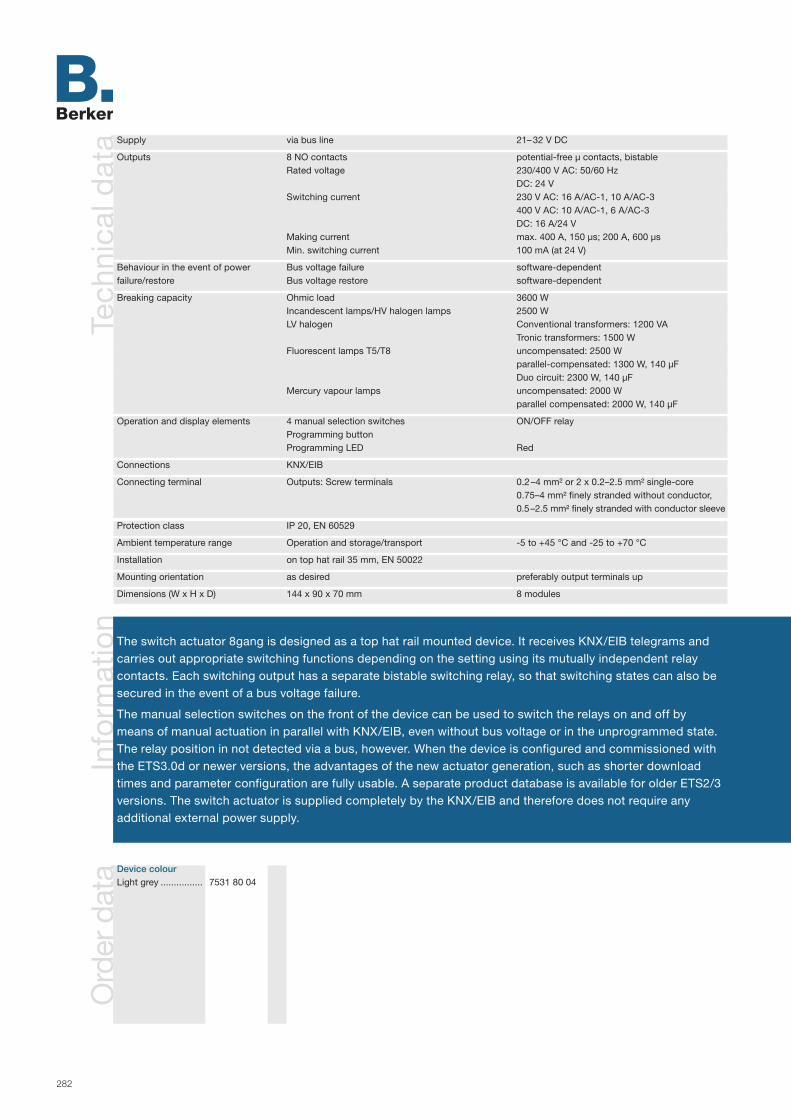
282
Info
rmat
ion
Ord
er d
ata
Tech
nica
l dat
a
The switch actuator 8gang is designed as a top hat rail mounted device. It receives KNX/EIB telegrams and carries out appropriate switching functions depending on the setting using its mutually independent relay contacts. Each switching output has a separate bistable switching relay, so that switching states can also be secured in the event of a bus voltage failure.
The manual selection switches on the front of the device can be used to switch the relays on and off by means of manual actuation in parallel with KNX/EIB, even without bus voltage or in the unprogrammed state. The relay position in not detected via a bus, however. When the device is configured and commissioned with the ETS3.0d or newer versions, the advantages of the new actuator generation, such as shorter download times and parameter configuration are fully usable. A separate product database is available for older ETS2/3 versions. The switch actuator is supplied completely by the KNX/EIB and therefore does not require any additional external power supply.
Device colourLight grey ................ 7531 80 04
Supply via bus line 21– 32 V DC
Outputs 8 NO contacts potential-free µ contacts, bistable Rated voltage 230/400 V AC: 50/60 Hz DC: 24 V Switching current 230 V AC: 16 A/AC-1, 10 A/AC-3 400 V AC: 10 A/AC-1, 6 A/AC-3 DC: 16 A/24 V Making current max. 400 A, 150 µs; 200 A, 600 µs Min. switching current 100 mA (at 24 V)
Behaviour in the event of power Bus voltage failure software-dependentfailure/restore Bus voltage restore software-dependent
Breaking capacity Ohmic load 3600 W Incandescent lamps/HV halogen lamps 2500 W LV halogen Conventional transformers: 1200 VA Tronic transformers: 1500 W Fluorescent lamps T5/T8 uncompensated: 2500 W parallel-compensated: 1300 W, 140 µF Duo circuit: 2300 W, 140 µF Mercury vapour lamps uncompensated: 2000 W parallel compensated: 2000 W, 140 µF
Operation and display elements 4 manual selection switches ON/OFF relay Programming button Programming LED Red
Connections KNX/EIB
Connecting terminal Outputs: Screw terminals 0.2 –4 mm² or 2 x 0.2–2.5 mm² single-core 0.75–4 mm² finely stranded without conductor, 0.5 –2.5 mm² finely stranded with conductor sleeve
Protection class IP 20, EN 60529
Ambient temperature range Operation and storage/transport -5 to +45 °C and -25 to +70 °C
Installation on top hat rail 35 mm, EN 50022
Mounting orientation as desired preferably output terminals up
Dimensions (W x H x D) 144 x 90 x 70 mm 8 modules

283
Ap
plic
atio
nsN
ote
s
Eight independent outputs
Outputs can be set as NO or NC
Potential-free bistable NO contacts 16 A
Manual selection switch with status indication for each output
Switch actuator 8gang 16 A NO manual status
ACTUATORS
Switching RS, LO, TF 208801 Independent switching of the eight outputs NO or NC operation can be setSwitching RS, LO, TF 208811 Central switching function with group feedback(for ETS 3 from version d) Switching feedback (only in bus operation): Active (when changed or cyclically) or passive (object can
be read out) feedback function can be set Logical linking function ("AND", "OR", "AND with return") for each output Blocking function can be set for each channel –alternatively forced setting function for each output Time functions (switch on delay, switch off delay, stair light function - also with pre-warning function) Can be included in light scenes, up to eight internal scenes can be set Operating hours meter can be activated for each output Input monitoring for cyclic updating with safety position Responses in the event of bus voltage failure and return and after an ETS programming process can
be set for each channel
Objects 106
Group addresses/assignments maximum 254/maximum 255
ETS search path: Berker >> Output >> Binary output, 8gang >>
Key1. Manual selection switch/ status indication2. Bus connection 3. Programming button 4. Programming LED
ATTENTIONSuitable for switching different external phase conductors.
When adjusted by means of a cen-tral telegram, the relay outputs of the switch actuator switch with a slight time delay. The connection of mains voltage and SELV/PELV electric circuits to a switch actua-tor is not permissible. The connection of three-phase motors is not permissible.
1
2
4 3
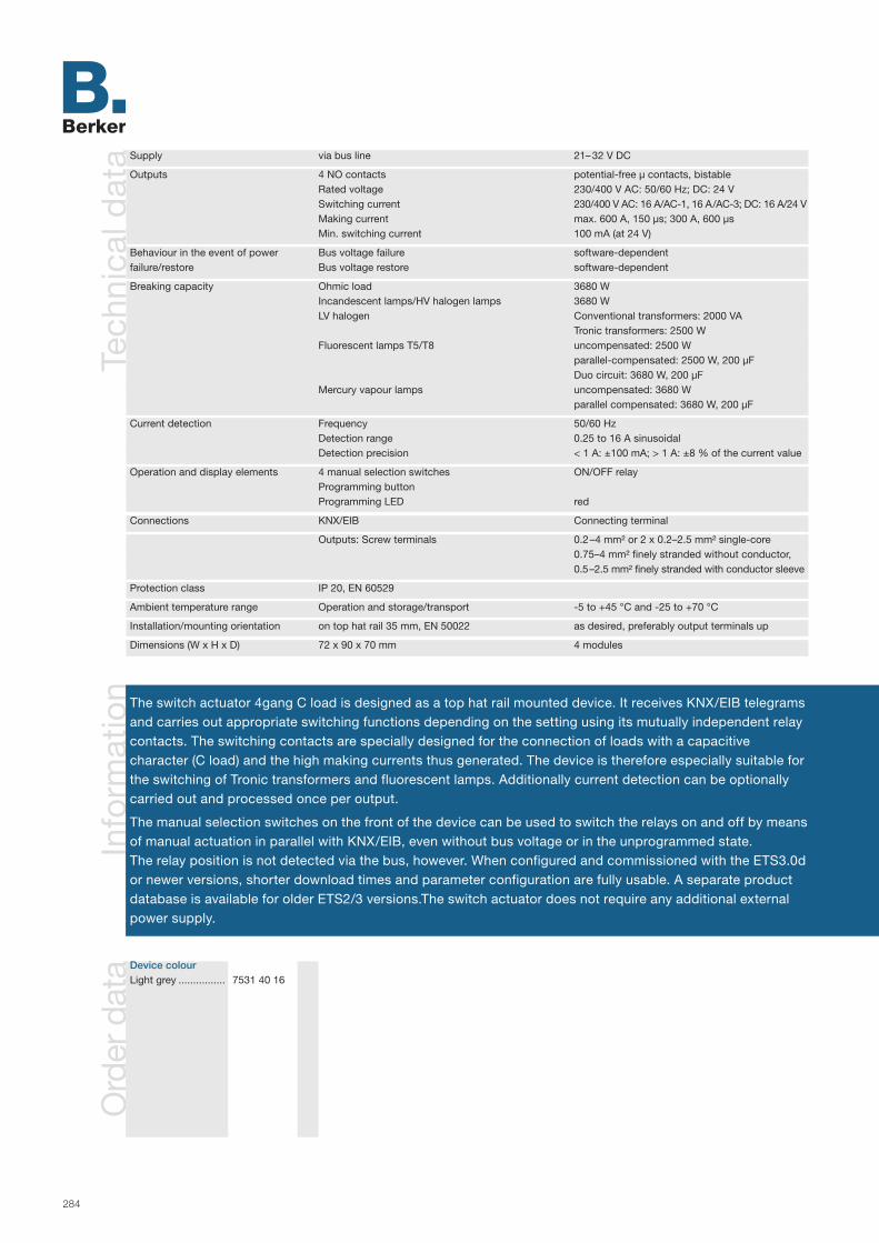
284
Info
rmat
ion
Ord
er d
ata
Tech
nica
l dat
a
Device colour Light grey ................ 7531 40 16
The switch actuator 4gang C load is designed as a top hat rail mounted device. It receives KNX/EIB telegrams and carries out appropriate switching functions depending on the setting using its mutually independent relay contacts. The switching contacts are specially designed for the connection of loads with a capacitive character (C load) and the high making currents thus generated. The device is therefore especially suitable for the switching of Tronic transformers and fluorescent lamps. Additionally current detection can be optionally carried out and processed once per output.
The manual selection switches on the front of the device can be used to switch the relays on and off by means of manual actuation in parallel with KNX/EIB, even without bus voltage or in the unprogrammed state. The relay position is not detected via the bus, however. When configured and commissioned with the ETS3.0d or newer versions, shorter download times and parameter configuration are fully usable. A separate product database is available for older ETS2/3 versions.The switch actuator does not require any additional external power supply.
Supply via bus line 21– 32 V DC
Outputs 4 NO contacts potential-free µ contacts, bistable Rated voltage 230/400 V AC: 50/60 Hz; DC: 24 V Switching current 230/400 V AC: 16 A/AC-1, 16 A /AC-3; DC: 16 A/24 V Making current max. 600 A, 150 µs; 300 A, 600 µs Min. switching current 100 mA (at 24 V)
Behaviour in the event of power Bus voltage failure software-dependentfailure/restore Bus voltage restore software-dependent
Breaking capacity Ohmic load 3680 W Incandescent lamps/HV halogen lamps 3680 W LV halogen Conventional transformers: 2000 VA Tronic transformers: 2500 W Fluorescent lamps T5/T8 uncompensated: 2500 W parallel-compensated: 2500 W, 200 µF Duo circuit: 3680 W, 200 µF Mercury vapour lamps uncompensated: 3680 W parallel compensated: 3680 W, 200 µF
Current detection Frequency 50/60 Hz Detection range 0.25 to 16 A sinusoidal Detection precision < 1 A: ±100 mA; > 1 A: ±8 % of the current value
Operation and display elements 4 manual selection switches ON/OFF relay Programming button Programming LED red
Connections KNX/EIB Connecting terminal
Outputs: Screw terminals 0.2 –4 mm² or 2 x 0.2–2.5 mm² single-core 0.75–4 mm² finely stranded without conductor, 0.5 –2.5 mm² finely stranded with conductor sleeve
Protection class IP 20, EN 60529
Ambient temperature range Operation and storage/transport -5 to +45 °C and -25 to +70 °C
Installation/mounting orientation on top hat rail 35 mm, EN 50022 as desired, preferably output terminals up
Dimensions (W x H x D) 72 x 90 x 70 mm 4 modules
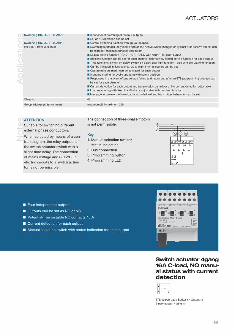
285
Ap
plic
atio
nsN
ote
s
Switch actuator 4gang 16 A C-load, NO manu-al status with current detection
ACTUATORS
Four independent outputs
Outputs can be set as NO or NC
Potential-free bistable NO contacts 16 A
Current detection for each output
Manual selection switch with status indication for each output
Switching RS, LO, TF 20A001 Independent switching of the four outputs NO or NC operation can be setSwitching RS, LO, TF 20A011 Central switching function with group feedback(for ETS 3 from version d) Switching feedback (only in bus operation): Active (when changed or cyclically) or passive (object can
be read out) feedback function can be set Logical linking function ("AND", "OR", "AND with return") for each output Blocking function can be set for each channel –alternatively forced setting function for each output Time functions (switch on delay, switch off delay, stair light function - also with pre-warning function) Can be included in light scenes, up to eight internal scenes can be set Operating hours meter can be activated for each output Input monitoring for cyclic updating with safety position Responses in the event of bus voltage failure and return and after an ETS programming process can
be set for each channel Current detection for each output and transmission behaviour of the current detection adjustable Load monitoring with fixed load limits or adjustable with teaching function Message in the event of overload and underload and transmitter behaviour can be set
Objects 66
Group addresses/assignments maximum 254/maximum 255
ETS search path: Berker >> Output >> Binary output, 4gang >>
ATTENTIONSuitable for switching different external phase conductors.
When adjusted by means of a cen-tral telegram, the relay outputs of the switch actuator switch with a slight time delay. The connection of mains voltage and SELV/PELV electric circuits to a switch actua-tor is not permissible.
The connection of three-phase motors is not permissible.
Key1. Manual selection switch/ status indication2. Bus connection 3. Programming button 4. Programming LED
1
2
4 3

286
Info
rmat
ion
Ord
er d
ata
Tech
nica
l dat
a
Device colour Light grey ................ 7531 80 05
The switch actuator 8gang C load is designed as a top hat rail mounted device. It receives KNX/EIB telegrams and carries out appropriate switching functions depending on the setting using its mutually independent relay contacts. The switching contacts are specially designed for the connection of loads with a capacitive charac-ter (C load) and the high making currents thus generated. The device is therefore especially suitable for the switching of Tronic transformers and fluorescent lamps. Additionally current detection can be optionally carried out and processed once per output.
The manual selection switches on the front of the device can be used to switch the relays on and off by means of manual actuation in parallel with KNX/EIB, even without bus voltage or in the unprogrammed state. The relay position is not detected via the bus, however. When configured and commissioned with the ETS3.0d or newer versions, shorter download times and parameter configuration are fully usable. A separate product database is available for older ETS2/3 versions.The switch actuator does not require any additional external power supply.
Supply via bus line 21– 32 V DCOutputs 4 NO contacts potential-free µ contacts, bistable Rated voltage 230/400 V AC: 50/60 Hz; DC: 24 V Switching current 230/400 V AC: 16 A/AC-1, 16 A /AC-3; DC: 16 A/24 V Making current max. 600 A, 150 µs; 300 A, 600 µs Min. switching current 100 mA (at 24 V)
Behaviour in the event of power Bus voltage failure software-dependentfailure/restore Bus voltage restore software-dependent
Breaking capacity Ohmic load 3680 W Incandescent lamps/HV halogen lamps 3680 W LV halogen Conventional transformers: 2000 VA Tronic transformers: 2500 W Fluorescent lamps T5/T8 uncompensated: 2500 W parallel-compensated: 2500 W, 200 µF Duo circuit: 3680 W, 200 µF Mercury vapour lamps uncompensated: 3680 W parallel compensated: 3680 W, 200 µF
Current detection Frequency 50/60 Hz Detection range 0.25 to 16 A sinusoidal Detection precision < 1 A: ±100 mA; > 1 A: ±8 % of the current value
Operation and display elements 4 manual selection switches ON/OFF relay Programming button Programming LED Red
Connections KNX/EIB Connecting terminal
Outputs: Screw terminals 0.2 –4 mm² or 2 x 0.2–2.5 mm² single-core 0.75–4 mm² finely stranded without conductor, 0.5 –2.5 mm² finely stranded with conductor sleeve
Protection class IP 20, EN 60529
Ambient temperature range Operation and storage/transport -5 to +45 °C and -25 to +70 °C
Installation/mounting orientation on top hat rail 35 mm, EN 50022 as desired, preferably output terminals up
Dimensions (W x H x D) 144 x 90 x 70 mm 8 modules
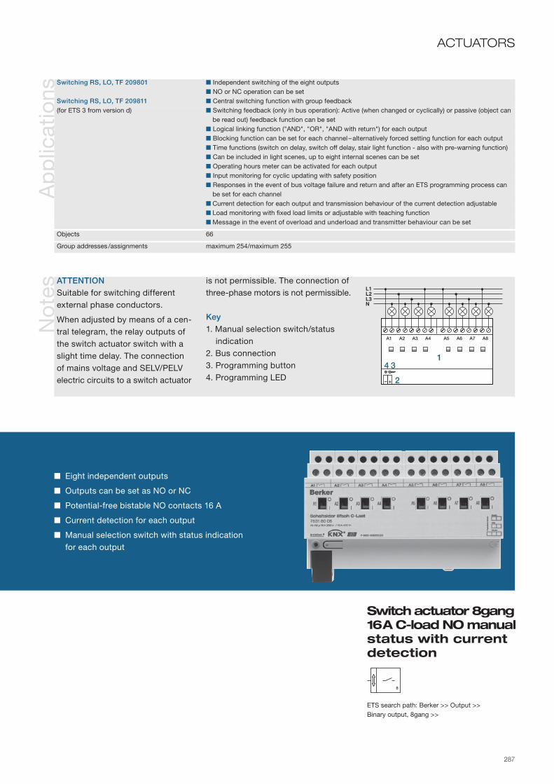
287
No
tes
Ap
plic
atio
nsACTUATORS
Eight independent outputs
Outputs can be set as NO or NC
Potential-free bistable NO contacts 16 A
Current detection for each output
Manual selection switch with status indication for each output
ETS search path: Berker >> Output >> Binary output, 8gang >>
ATTENTIONSuitable for switching different external phase conductors.
When adjusted by means of a cen-tral telegram, the relay outputs of the switch actuator switch with a slight time delay. The connection of mains voltage and SELV/PELV electric circuits to a switch actuator
is not permissible. The connection of three-phase motors is not permissible.
Key1. Manual selection switch/status indication2. Bus connection 3. Programming button 4. Programming LED
Switching RS, LO, TF 209801 Independent switching of the eight outputs NO or NC operation can be setSwitching RS, LO, TF 209811 Central switching function with group feedback(for ETS 3 from version d) Switching feedback (only in bus operation): Active (when changed or cyclically) or passive (object can
be read out) feedback function can be set Logical linking function ("AND", "OR", "AND with return") for each output Blocking function can be set for each channel – alternatively forced setting function for each output Time functions (switch on delay, switch off delay, stair light function - also with pre-warning function) Can be included in light scenes, up to eight internal scenes can be set Operating hours meter can be activated for each output Input monitoring for cyclic updating with safety position Responses in the event of bus voltage failure and return and after an ETS programming process can
be set for each channel Current detection for each output and transmission behaviour of the current detection adjustable Load monitoring with fixed load limits or adjustable with teaching function Message in the event of overload and underload and transmitter behaviour can be set
Objects 66
Group addresses /assignments maximum 254/maximum 255
1
2
4 3
Switch actuator 8gang 16 A C-load NO manu al status with current detection
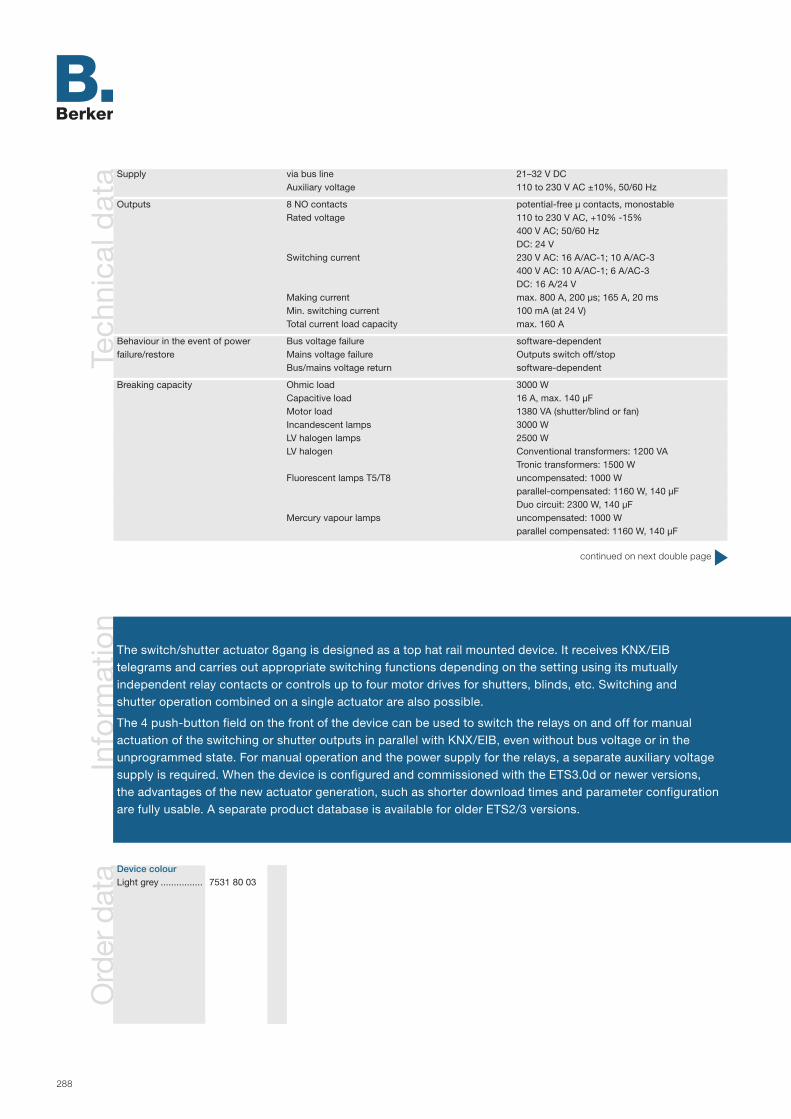
288
Info
rmat
ion
Ord
er d
ata
Tech
nica
l dat
a
Device colour Light grey ................ 7531 80 03
The switch/shutter actuator 8gang is designed as a top hat rail mounted device. It receives KNX/EIB telegrams and carries out appropriate switching functions depending on the setting using its mutually in dependent relay contacts or controls up to four motor drives for shutters, blinds, etc. Switching and shutter operation combined on a single actuator are also possible.
The 4 push-button field on the front of the device can be used to switch the relays on and off for manual actuation of the switching or shutter outputs in parallel with KNX/EIB, even without bus voltage or in the unprogrammed state. For manual operation and the power supply for the relays, a separate auxiliary voltage supply is required. When the device is configured and commissioned with the ETS3.0d or newer versions, the advantages of the new actuator generation, such as shorter download times and parameter configuration are fully usable. A separate product database is available for older ETS2/3 versions.
Supply via bus line 21–32 V DC Auxiliary voltage 110 to 230 V AC ±10%, 50/60 Hz
Outputs 8 NO contacts potential-free µ contacts, monostable Rated voltage 110 to 230 V AC, +10% -15% 400 V AC; 50/60 Hz DC: 24 V Switching current 230 V AC: 16 A/AC-1; 10 A/AC-3 400 V AC: 10 A/AC-1; 6 A/AC-3 DC: 16 A/24 V Making current max. 800 A, 200 µs; 165 A, 20 ms Min. switching current 100 mA (at 24 V) Total current load capacity max. 160 A
Behaviour in the event of power Bus voltage failure software-dependentfailure/restore Mains voltage failure Outputs switch off/stop Bus/mains voltage return software-dependent
Breaking capacity Ohmic load 3000 W Capacitive load 16 A, max. 140 µF Motor load 1380 VA (shutter/blind or fan) Incandescent lamps 3000 W LV halogen lamps 2500 W LV halogen Conventional transformers: 1200 VA Tronic transformers: 1500 W Fluorescent lamps T5/T8 uncompensated: 1000 W parallel-compensated: 1160 W, 140 µF Duo circuit: 2300 W, 140 µF Mercury vapour lamps uncompensated: 1000 W parallel compensated: 1160 W, 140 µF
continued on next double page

289
Ap
plic
atio
ns
Switch/shutter actuator 8/4gang 16 A NO manual status
ACTUATORS
Combination unit for switching or control of motor drives
Outputs can be set as NO or NC
Eight potential-free NO contacts 16 A
Four push-buttons with LED display for manual operation
LED status indication for each channel
Switching shutter 208002 Shutter or switching operation can be set for the eight outputs, in shutter operation each pair of two neighbouring outputs are combined into a shutter output
Switching shutter 208012 Responses in the event of bus voltage failure and return can be set for each output(for ETS 3 from version d) Delay for active feedback after bus voltage return can be adjusted Manual operation can be blocked
Shutter operation Activation of lamella shutters, blinds or ventilation flaps adjustable Separately paramet. operation times with operation time extension for moving to the upper end position Central activation of all shutter outputs possible Active and passive (object can be read out) feedback of the shutter position or lamella position Assignments to up to five different safety functions (3 wind, 1 rain, 1 frost alarm), if desired with cyclic
monitoring Forced setting function can implemented for each shutter output Extensive sun shade function can be set for each output Can be included in scenes: Up to eight internal scenes can be set
Switching operation NO or NC operation can be set Central switching function with group feedback Active and passive (object can be read out) feedback of the switching state Logical linking function ("AND", "OR", "AND with return") for each output Blocking function can be paramet. for each channel –alternatively forced setting function for each output Time functions (switch on delay, switch off delay, stair light function - also with pre-warning function) Can be included in light scenes, up to eight internal scenes can be set
Objects: 76
Group addresses/assignments: maximum 254/maximum 255
ETS search path: Berker >> Output >> Binary output, mix >>
continued on next double page

290
Info
rmat
ion
Tech
nica
l dat
a Operation and display elements Button field 4gang Local operation 3 status LEDs on-the-spot operation Red 8 status LEDs outputs Red Programming button Programming LED Red
Connections KNX/EIB Connecting terminal Outputs: Screw terminals 0.2 –4 mm² or 2 x 0.2–2.5 mm² single-core 0.75–4 mm² finely stranded without conductor, 0.5 –2.5 mm² finely stranded with conductor sleeve
Protection class IP 20, EN 60529
Ambient temperature range Operation -5 to +45 °C Storage/transport -25 to +70 °C
Installation/mounting orientation on top hat rail 35 mm, EN 50022 as desired preferably output terminals up
Dimensions (W x H x D) 72 x 90 x 70 mm 4 modules

291
No
tes
ACTUATORS(Continued)
Key1. Connecting terminal auxiliary voltage2. Programming button3. Bus connection4. Programming LED5. Buttons 1/5 and 0 /6 each with associated LED6. Manual button with associated LED7. ALL OFF button8. Status LEDs of the outputs9. Outputs
ATTENTIONSuitable for switching different external phase conductors.
The mains voltage must be present in order to activate the outputs.
The connection of mains voltage and SELV/PELV electric circuits to a switch actuator is not permissible.
The connection of three-phase motors is not permissible.
Switch/shutter actuator 8/4gang 16 A NO manual status
3
78
54
6
21
9

292
Info
rmat
ion
Ord
er d
ata
Tech
nica
l dat
a
Device colour Light grey ................ 7531 00 02
The switch/shutter actuator 16gang is designed as a top hat rail mounted device. It receives KNX/EIB telegrams and carries out appropriate switching functions depending on the setting using its mutually inde-pendent relay contacts or controls up to eight motor drives for shutters, blinds, etc. Switching and shutter operation combined on a single actuator are also possible.
The 4 push-button field on the front of the device can be used to switch the relays on and off for manual actuation of the switching or shutter outputs in parallel with KNX/EIB, even without bus voltage or in the unprogrammed state. For manual operation and the power supply for the relays, a separate auxiliary voltage supply is required.
When the device is configured and commissioned with the ETS3.0d or newer versions, the advantages of the new actuator generation, such as shorter download times and parameter configuration are fully usable. A separate product database is available for older ETS2/3 versions.
Supply via bus line 21–32 V DC Auxiliary voltage 110 to 230 V AC ±10%, 50/60 Hz
Outputs 16 NO contacts potential-free µ contacts, monostable Rated voltage 110 to 230 V AC, +10% -15% 400 V AC; 50/60 Hz DC: 24 V Switching current 230 V AC: 16 A/AC-1; 10 A/AC-3 400 V AC: 10 A/AC-1; 6 A/AC-3 DC: 16 A/24 V Making current max. 800 A, 200 µs; 165 A, 20 ms Switching current min. 100 mA (at 24 V) Total current load capacity max. 160 A
Behaviour in the event of power Bus voltage failure software-dependentfailure/restore Mains voltage failure Outputs switch off/stop Bus/mains voltage return software-dependent
Breaking capacity Ohmic load 3000 W Capacitive load 16 A, max. 140 µF Motor load 1380 VA (shutter/blind or fan) Incandescent lamps 3000 W LV halogen lamps 2500 W LV halogen Conventional transformers: 1200 VA Tronic transformers: 1500 W Fluorescent lamps T5/T8 uncompensated: 1000 W parallel-compensated: 1160 W, 140 µF Duo circuit: 2300 W, 140 µF Mercury vapour lamps uncompensated: 1000 W parallel compensated: 1160 W, 140 µF
continued on next double page

293
Ap
plic
atio
ns
Switch/shutter actuator 16/8gang 16 A NO manual, status
ACTUATORS
Combination unit for switching or control of motor drives
Outputs can be set as NO or NC
Sixteen potential-free NO contacts 16 A
Four push-buttons with LED display for manual operation
LED status indication for each channel
Switching/shutter 207802 Shutter or switching operation can be set for the sixteen outputs, in shutter operation each pair of two neighbouring outputs are combined into a shutter output Switching/shutter 207812 Responses in the event of bus voltage failure and return can be set for each output(for ETS 3 from version d) Delay for active feedback after bus voltage return can be adjusted Manual operation can be blocked
Shutter operation Activation of lamella shutters, blinds or ventilation flaps adjustable Separately paramet. operation times with operation time extension for moving to the upper end position Central activation of all shutter outputs possible Active and passive (object can be read out) feedback of the shutter position or lamella position Assignments to up to five different safety functions (3 wind, 1 rain, 1 frost alarm), if desired with cyclic
monitoring Forced setting function can implemented for each shutter output Extensive sun shade function can be set for each output Can be included in scenes: Up to eight internal scenes can be set
Switching operation NO or NC operation can be set Central switching function with group feedback Active and passive (object can be read out) feedback of the switching state Logical linking function ("AND", "OR", "AND with return") for each output Blocking function can be paramet. for each channel –alternatively forced setting function for each output Time functions (switch on delay, switch off delay, stair light function - also with pre-warning function) Can be included in light scenes, up to eight internal scenes can be set
Objects: 122
Group addresses/assignments: maximum 254/maximum 255
ETS search path: Berker >> Output >> Binary output, mix >>
continued on next double page

294
Info
rmat
ion
Tech
nica
l dat
a Operation and display elements Button field 4gang Local operation 3 status LEDs for local operation Red 8 status LEDs outputs Red Programming button Programming LED Red
Connections KNX/EIB Connecting terminal Outputs: Screw terminals 0.2–4 mm² or 2 x 0.2–2.5 mm² single-core 0.75–4 mm² finely stranded without conductor, 0.5 –2.5 mm² finely stranded with conductor sleeve
Protection class IP 20, EN 60529
Ambient temperature range Operation -5 to +45 °C Storage/transport -25 to +70 °C
Installation/mounting orientation on top hat rail 35 mm, EN 50022 as desired preferably output terminals up
Dimensions (W x H x D) 144 x 90 x 70 mm 8 modules

295
No
tes
ACTUATORS(Continued)
ATTENTIONSuitable for switching different external phase conductors.
The mains voltage must be present in order to activate the outputs.
The connection of mains voltage and SELV/PELV electric circuitsto a switch actuator is not permissible.
The connection of three-phase motors is not permissible.
Key1. Connecting terminal auxiliary voltage2. Programming button3. Bus connection4. Programming LED5. Buttons 1/5and 0 /6 each with associated LED6. Manual button with associated LED7. Off/bus operation button8. Status LEDs of the outputs9. Outputs
Switch/shutter actuator 16/8gang 16 A NO manual, status
3
7 8
54
6
21
9

296
Info
rmat
ion
Ord
er d
ata
Tech
nica
l dat
a
Device colour Light grey ................ 7534 10 01
The switch actuator 1gang is designed as a flush-mounted device. It receives telegrams from sensors via the instabus KNX/EIB and switches electrical loads with its relay contact.
The device also has two extension unit inputs that can operate either directly on the switching output (local operation of the switching output by input 1) or also alternatively as binary outputs on the bus, depending on the parameterisation. The connected potential-free switching or push-button contacts are read in via a common reference potential on the switch actuator.
Telegrams for switching or dimming, for shutter control or value transmitter applications (dimming value transmitter, light scene extension unit) can be sent out via the binary inputs.
The switch actuator is supplied by the KNX/EIB and therefore does not require any additional external power supply.
Supply via bus line 21–32 V DC
Inputs Number max. 2 Cable length 33 cm pre-assembled, max. 5 m Scanning voltage approx. - 19 V DC; continuous signal
Outputs 1 NO contact potential-free µ contact, bistable Rated voltage 230 V AC; 50 60 Hz Switching current max. 16 A Making current max. 400 A, 20 ms
Behaviour in the event Outputs Dependent on the parameterisationof bus voltage failure Inputs No response
Behaviours in the event of Outputs Dependent on the parameterisationbus voltage return Inputs Dependent on the parameterisation
Breaking capacity Incandescent lamps 2500 W HV halogen lamps 2200 W LV halogen Conventional transformers: 1000 VA Tronic transformers: 1000 W Capacitive load 230 V AC, 10 A nominal current, max. 105 µF
Operation and display elements Programming button Programming LED Red
Connections KNX/EIB Pre-assem. connecting cable, connecting terminal Inputs Pre-assem. connecting cable: YY 6 x 0.6 mm2
Output Pre-assem. connecting cable: 2 x H05 V-K 2.5 mm2
with conductor sleeves
Protection class IP 20, EN 60529
Ambient temperature range Operation -5 to +45 °C Storage/transport -25 to +70 °C
Installation e.g. insertion in deep flush-mounted box Ø 60 mm
Mounting orientation as desired
Dimensions (Ø x H) 53 x 28 mm Hole in the centre of the actuator: Ø = 7 mm
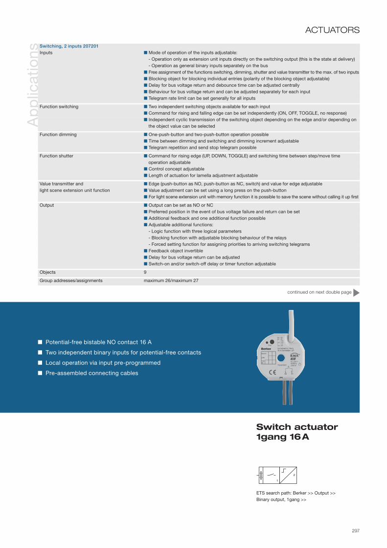
297
Ap
plic
atio
ns
Switch actuator 1gang 16 A
ACTUATORS
Potential-free bistable NO contact 16 A
Two independent binary inputs for potential-free contacts
Local operation via input pre-programmed
Pre-assembled connecting cables
Switching, 2 inputs 207201 Inputs Mode of operation of the inputs adjustable: - Operation only as extension unit inputs directly on the switching output (this is the state at delivery) - Operation as general binary inputs separately on the bus Free assignment of the functions switching, dimming, shutter and value transmitter to the max. of two inputs Blocking object for blocking individual entries (polarity of the blocking object adjustable) Delay for bus voltage return and debounce time can be adjusted centrally Behaviour for bus voltage return and can be adjusted separately for each input Telegram rate limit can be set generally for all inputs
Function switching Two independent switching objects available for each input Command for rising and falling edge can be set independently (ON, OFF, TOGGLE, no response) Independent cyclic transmission of the switching object depending on the edge and/or depending on
the object value can be selected
Function dimming One-push-button and two-push-button operation possible Time between dimming and switching and dimming increment adjustable Telegram repetition and send stop telegram possible
Function shutter Command for rising edge (UP, DOWN, TOGGLE) and switching time between step/move time operation adjustable Control concept adjustable Length of actuation for lamella adjustment adjustable
Value transmitter and Edge (push-button as NO, push-button as NC, switch) and value for edge adjustablelight scene extension unit function Value adjustment can be set using a long press on the push-button For light scene extension unit with memory function it is possible to save the scene without calling it up first
Output Output can be set as NO or NC Preferred position in the event of bus voltage failure and return can be set Additional feedback and one additional function possible Adjustable additional functions: - Logic function with three logical parameters - Blocking function with adjustable blocking behaviour of the relays - Forced setting function for assigning priorities to arriving switching telegrams Feedback object invertible Delay for bus voltage return can be adjusted Switch-on and/or switch-off delay or timer function adjustable
Objects 9
Group addresses/assignments maximum 26/maximum 27
ETS search path: Berker >> Output >> Binary output, 1gang >>
continued on next double page

298
Info
rmat
ion

299
No
tes ATTENTION
The connection of 230 V signals or other external voltages to the extension unit inputs is not per-missible!
Minimum distance between bus/extension unit cores and mains voltage cores 4 mm. RecommendationInstall the switch actuator in two interconnected flush-mounted boxes (see illustration at right). One box (9) can house the bus and extension unit connection and also a series switch (10), for example.
The other box (7) houses the the switch actuator and the 230 V terminals. The 6pole connecting cable (8) is routed through the connection between the boxes.
Key1. KNX/EIB connection (red/black)2. Input 1 (green/white)3. Input 2 (yellow/brown)4. Bus and extension unit connection5. Programming button6. Programming LED7. Flush-mounted box for switch actuator 1gang8. 6pole connecting cable9. Flush-mounted box for e. g. series switch10. Series switch
ACTUATORS(Continued)
Switch actuator 1gang 16 A
456
3217
8
9
10
Connection diagram for e. g. a series switch

300
Info
rmat
ion
Ord
er d
ata Device colour
Light grey ................ 7534 20 01
The switch actuator 2gang is designed as a flush-mounted device. It receives telegrams from sensors via the instabus KNX/EIB and switches electrical loads with its two relay contacts.
The device also has two extension unit inputs that can operate either directly on the switching output (local operation) or also alternatively as binary outputs on the bus, depending on the parameterisation.
The connected potential-free switching or push-button contacts are read in via a common reference potential on the switch actuator. Telegrams for switching or dimming, for shutter control or value transmitter applica-tions (dimming value transmitter, light scene extension unit) can be sent out via the binary inputs.
The switch actuator is supplied by the KNX/EIB and therefore does not require any additional external power supply.
Tech
nica
l dat
a Supply via bus line 21–32 V DC
Inputs Number max. 2 Cable length 33 cm pre-assembled, max. 5 m Scanning voltage approx. - 19 V DC; continuous signal
Outputs 2 NO contacs potential-free µ contact, bistable Rated voltage 230 V AC; 50 60 Hz Switching current max. 6 A Making current max. 120 A, 20 ms
Behaviour in the event Outputs Dependent on the parameterisationof bus voltage failure Inputs No response
Behaviours in the event of Outputs Dependent on the parameterisationbus voltage return Inputs Dependent on the parameterisation
Breaking capacity Incandescent lamps 1200 W HV halogen lamps 1200 W LV halogen Conventional transformers: 500 VA Tronic transformers: 500 W Capacitive load 230 V AC, 6 A nominal current, max. 14 µF
Operation and display elements Programming button Programming LED Red
Connections KNX/EIB Pre-assem. connecting cable, connecting terminal Inputs Pre-assem. connecting cable: YY 6 x 0.6 mm2
Output Pre-assem. connecting cable: 2 x H05 V-K 2.5 mm2
with conductor sleeves
Protection class IP 20, EN 60529
Ambient temperature range Operation -5 to +45 °C Storage/transport -25 to +70 °C
Installation e. g. insertion in deep flush-mounted box Ø 60 mm x 60 mm
Mounting orientation as desired
Dimensions (Ø x H) 53 x 28 mm Hole in the centre of the actuator: Ø = 7 mm

301
Ap
plic
atio
nsN
ote
s
Switch actuator 2gang 6 A
ACTUATORS
Potential-free bistable NO contacts 6 A
Two independent binary inputs for potential-free contacts
Local operation via inputs pre-programmed
Pre-assembled connecting cables
Switching, 2 inputs 207101 Inputs like previous device
Function switching like previous device
Function dimming like previous device
Function shutter like previous device
Value transmitter and light scene extension unit function like previous device
Outputs like previous device
Objects 12
Group addresses maximum 26
Assignments maximum 27
ETS search path: Berker >> Output >> Binary output, 2gang >>
ATTENTIONThe connection of 230 V signals or other external voltages to the extension unit inputs is not per-missible!
Not suitable for connection of different external conductors!
Minimum distance between bus/extension unit cores and mains voltage cores 4 mm.
Installation recommendation See previous page.
Key1. KNX/EIB connection (red/black)2. Input 1 (green/white)3. Input 2 (yellow/brown)4. Bus and extension unit connection5. Programming button6. Programming LED
456
321

302
Info
rmat
ion
Ord
er d
ata Device colour
Light grey ................ 7531 10 07
Tech
nica
l dat
a
The universal dim actuator 1gang is executed as a top hat rail mounted device. It operates on the generalized phase cut-on or phase cut-off principle, and permits switching and dimming of incandescent lamps, HV halogen lamps and LV halogen lamps with conventional or Tronic transformers.
The characteristic of the connected load is automatically calibrated and the dimmer actuator is set to the appropriate dimming method.
Supply via bus line 21–32 V DC Supply voltage via connected phase lead (2-wire system)
Outputs Switch type Power MOS-FET (phase rising or falling zero transit) Rated voltage 230 V AC ±10 %, 50 to 60 Hz Rated current 2.2 A Minimum load 50 W (if output switched) Overall power loss maximum 4.5 W
Behaviour on power Bus or mains power failure Dimmer actuator switches offfailure/restoration Bus and mains power failure Dimmer actuator switches off Bus power restoration Software-dependent Mains power restoration Dimmer actuator adjusts brightness according to object value Bus and mains power restoration Software-dependent
Dimming capacity Resistive load, incandescent lamps, HV halogen lamps, LV halogen lamps with electronic or conventional transformer 50–500 W/VA in each case
Operation and display elements Programming button Programming LED Red
Connections KNX/EIB terminals Outputs screw terminals 0.25– 4 mm2
Protection IP 20, EN 60529
Ambient temperature range Operation - 5 to + 45 °C Storage/transport - 25 to + 70 °C
Mounting on top hat rail 35 mm, EN 50022
Mounting orientation any
Dimensions (W×H×D) 72 x 90 x 58 mm 4 modules

303
Universal dim actuator 1gang 50–500 W/VA
ACTUATORS
ETS search path: Berker >> Illumination >> Dimmer >>
Ap
plic
atio
ns
Dimming 301701 Switching and dimming of lights “Dim-down” or “Jump onto” preset brightness levels function Switch-on and dimming response programmable “Soft-ON”, “Soft-OFF” and “timed dimmer” (stairwell light function) programmable Time-delayed switch-off when basic brightness reached or when light falls below basic brightness level Switching status/dimming value indication object Light scene mode – retrieval of up to eight brightness values as light scenes Activation of a lockout mode – brightness value at beginning and end of lockout programmable Response to bus power restoration programmable Overload detection
Objects 9
Group addresses/assignments maximum of 27 each
No
tes
Key1. Bus connection2. Programming button3. Programming LED
L1
+–
L2L3N
L
Automatic calibration to connected load
Energy-saving softstart
Dimming rate and basic brightness configurable
Revertive signal (feedback) of switching state
Overheating protection
Electronic shorting and overload protection
1
1
3 2

304
Info
rmat
ion
Ord
er d
ata Device colour
Light grey ................ 7531 20 07
Tech
nica
l dat
a
The universal switch actuator 2gang is executed as a top hat rail mounted device. It operates on the genera-lized phase cut-on or phase cut-off principle, and permits switching and dimming of bulbs, HV halogen lamps and LV halogen lamps with conventional or Tronic transformers.
The characteristic of the connected load is automatically calibrated and the dim actuator is set to the appro-priate dimming method.
Supply via bus line 21–32 V DC Supply voltage via connected outer conductor (two-wire technique)
Outputs Switch type Power MOS-FET Rated voltage 230 V AC Rated current 2 x 1 A Minimum load 50 W per channel Total power loss maximum 4.5 W (both channels)
Response to power Bus or mains power failure Dim actuator switches offfailure/restoration Bus and mains power failure Dim actuator switches off Bus power restoration programmable Mains power restoration Dim actuator adjusts brightness according to object value Bus and mains power restoration programmable
Dimming capacity Bulbs, HV halogen lamps, LV halogen lamps with electronic or conventional transformer 50 – 300 W/VA each
Operation and display elements Programming button Programming LED Red
Connections KNX/EIB Pressure contact on data rail Outputs Screw-type terminals 0.25 – 4 mm2
Protection IP 20, EN 60529
Ambient temperature range Operation -5 to +45 °C Storage/transportation -25 to +70 °C
Mounting on top hat rail 35 mm, EN 50022 No minimum clearances
Mounting orientation any
Dimensions (WxHxD) 72 x 90 x 58 mm 4 modules

305
Automatic calibration to connected load
Energy-saving softstart
Dimming rate and basic brightness configurable
Revertive signal (feedback) of switching state
Overheating protection
Electronic shorting and overload protection
Universal dim actuator 2gang 2 x 300 W/VA
ACTUATORS
ETS search path: Berker >> Illumination >> Dimmer >>
Ap
plic
atio
ns
Dimming 301501 Switching and dimming of lights “Dim-down” or “Jump onto” preset brightness levels function Switch-on and dimming response programmable “Soft-ON”, “Soft-OFF” and “timed dimmer” (stairwell light function) programmable Time-delayed switch-off when basic brightness reached or when light falls below basic brightness level Switching status/dimming value indication object Light scene mode – retrieval of up to eight brightness values as light scenes Activation of a lockout mode – brightness value at beginning and end of lockout programmable Response to bus power restoration programmable Overload detection
Objects 18
Group addresses/assignments maximum 34/maximum 28
No
tes
Key1. Bus connection2. Programming button3. Programming LED
2
L1L2L3N
A1 A2
+–
L
1
3 2
ATTENTIONSuitable for switching and dim-ming different external phase conductors.

306
Info
rmat
ion
Ord
er d
ata
Tech
nica
l dat
a
Device colour Light grey ................ 7531 40 17
The dim actuator 4gang is designed as a top hat rail mounted device. It operates according to the phase cut-on and phase cut-off principle, and makes it possible to switch and dim different lamp loads on four out-puts. The characteristic of the connected load is calibrated automatically and the suitable dimming process is set, although the setting can also be made manually using the programming software.
The manual selection switches on the front of the device can be used to switch and dim the connected loads by means of manual actuation in parallel with KNX/EIB, even without bus voltage or in the unpro-grammed state.
When the device is configured and commissioned with the ETS3.0d or newer versions, the advantages of the new actuator generation, such as shorter download times and parameter configuration are fully usable. A separate product database is available for older ETS2/3 versions.
The device requires a separate auxiliary voltage supply.
Supply via bus line 21– 32 V DC
Auxiliary voltage AC 190 to 230 V ~ +10/-15 %; 50/60 Hz
Outputs Switch type Power MOS-FET (phase cut-on or phase cut-off) Rated voltage 230 V AC; 50/60 Hz Minimum load 20 W/ VA (if output connected) Total power loss max. 10 W
Behaviour in the event of power Bus voltage failure software-dependentfailure/restore Mains voltage failure Loads are switched off Bus/mains voltage return software-dependent
Dimming capacity Incandescent lamps, HV halogen lamps LV halogen lamps with electronic or conventional transformer each 20 –210 W/VA
Operation and display elements Button field 4gang Local operation 3 status LEDs local operation Red 8 status LEDs outputs Red Programming button Programming LED Red
Connections KNX/EIB Connecting terminal Outputs: Screw terminals 0.5–4 mm² single/finely stranded without conductor sleeve 0.5–2.5 mm² finely stranded with conductor sleeve
Protection IP 20, EN 60529
Ambient temperature range Operation -5 to +45 °C Operation and storage/transport -25 to +70 °C
Installation on top hat rail 35 mm, EN 50022
Mounting orientation as desired preferably output terminals up
Dimensions (W x H x D) 144 x 90 x 70 mm 8 modules

307
Ap
plic
atio
nsN
ote
s
Universal dim actuator 4gang 20 –210 W/VA manual status
ACTUATORS
Four outputs for switching and dimming
Automatic calibration of the connected load
Bulb-preserving soft start
Thermal overload protection
Electronic short-circuit and overload protection
Manual selection switch with status indication for each output
ETS search path: Berker >> Illumination >> Dimmer >>
Dimming 301A01 Independent activation of up to 4 dimming outputs Manual actuation of the outputs possible independently from the bus (building site operation)Dimming 301A11 Central switching function for common activation of all outputs(for ETS 3 from version d) Switching feedback: active or passive (object can be read out) feedback function Load type can be set for each output: - universal (with automatic calibration process) - electronic transformer (capacitive/phase cut-off principle) - conventional transformer (inductive/phase cut-on principle) Brightness limit values for basic and maximum brightness adjustable Dimming behaviour (including fading) and dimming characteristic curves adjustable Soft switch-on or soft switch-off function adjustable Transmission of message telegrams to the bus for each output in the event of short-circuit/overload and in the event of a load drop-out adjustable Feedback of the connected load type possible Blocking function or alternatively forced setting function for each output adjustable Time functions (switch-on, switch-off delay, stair light function - also with pre-warning function) adjustable Operating hours meter can be activated for each output Outputs can be included in up to 8 scenes Responses in the event of bus voltage failure and return and after an ETS programming process can be set for each group
Objects 75
Group addresses/assignments maximum 254/maximum 255
Key1. Connecting terminal auxiliary
voltage2. Programming button3. Bus connection4. Programming LED5. Push-buttons 1/5and 0 /6each
with associated LED6. Manual button with associated LED7. OFF button
8. Status LED of the outputs9. Outputs
3
78
54
6
2 1
9
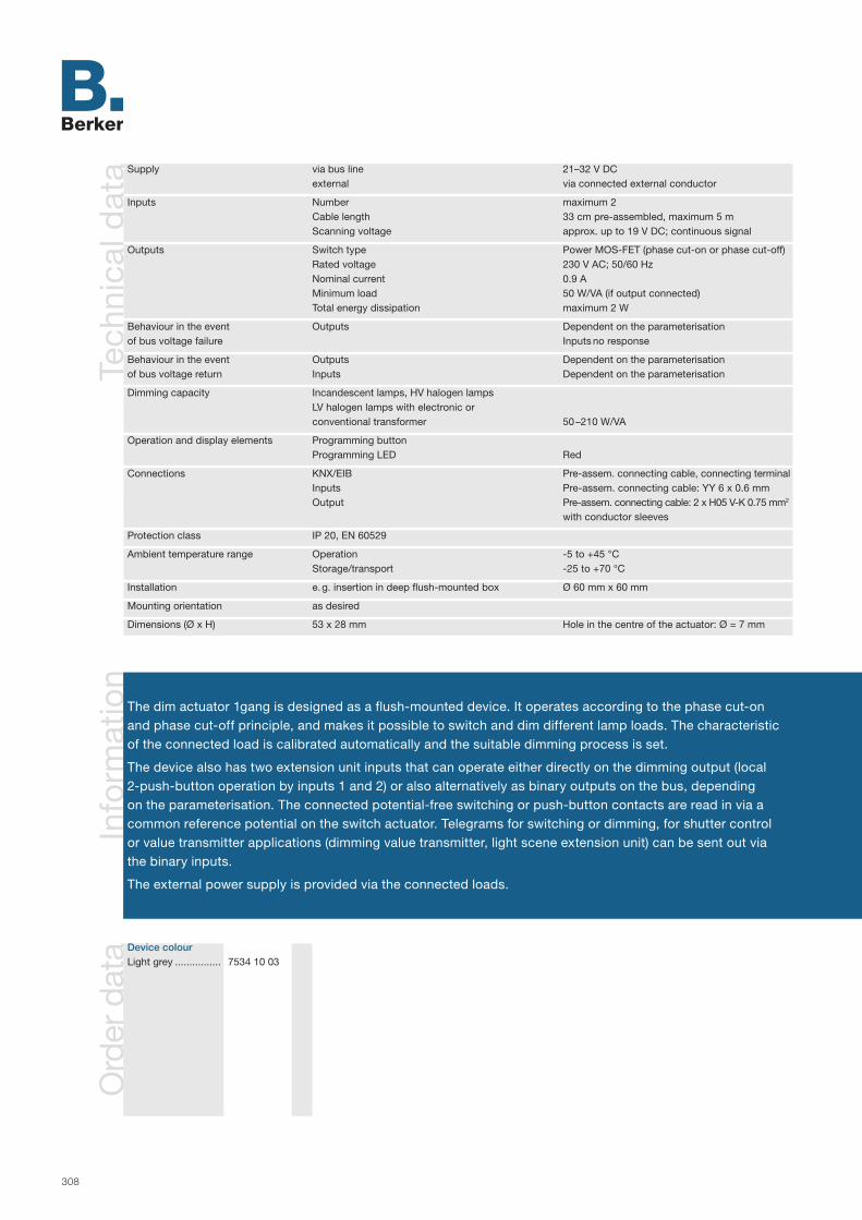
308
Info
rmat
ion
Ord
er d
ata
Tech
nica
l dat
a
Device colour Light grey ................ 7534 10 03
The dim actuator 1gang is designed as a flush-mounted device. It operates according to the phase cut-on and phase cut-off principle, and makes it possible to switch and dim different lamp loads. The characteristic of the connected load is calibrated automatically and the suitable dimming process is set.
The device also has two extension unit inputs that can operate either directly on the dimming output (local 2-push-button operation by inputs 1 and 2) or also alternatively as binary outputs on the bus, depending on the parameterisation. The connected potential-free switching or push-button contacts are read in via a common reference potential on the switch actuator. Telegrams for switching or dimming, for shutter control or value transmitter applications (dimming value transmitter, light scene extension unit) can be sent out via the binary inputs.
The external power supply is provided via the connected loads.
Supply via bus line 21–32 V DC external via connected external conductor
Inputs Number maximum 2 Cable length 33 cm pre-assembled, maximum 5 m Scanning voltage approx. up to 19 V DC; continuous signal
Outputs Switch type Power MOS-FET (phase cut-on or phase cut-off) Rated voltage 230 V AC; 50/60 Hz Nominal current 0.9 A Minimum load 50 W/VA (if output connected) Total energy dissipation maximum 2 W
Behaviour in the event Outputs Dependent on the parameterisationof bus voltage failure Inputs no response
Behaviour in the event Outputs Dependent on the parameterisationof bus voltage return Inputs Dependent on the parameterisation
Dimming capacity Incandescent lamps, HV halogen lamps LV halogen lamps with electronic or conventional transformer 50 –210 W/VA
Operation and display elements Programming button Programming LED Red
Connections KNX/EIB Pre-assem. connecting cable, connecting terminal Inputs Pre-assem. connecting cable: YY 6 x 0.6 mm Output Pre-assem. connecting cable: 2 x H05 V-K 0.75 mm2 with conductor sleeves
Protection class IP 20, EN 60529
Ambient temperature range Operation -5 to +45 °C Storage/transport -25 to +70 °C
Installation e. g. insertion in deep flush-mounted box Ø 60 mm x 60 mm
Mounting orientation as desired
Dimensions (Ø x H) 53 x 28 mm Hole in the centre of the actuator: Ø = 7 mm

309
Ap
plic
atio
ns
Universal dim actuator 1gang 50 –210 W/VA
ACTUATORS
Automatic calibration of the connected load
Bulb-preserving soft start
Thermal overload protection
Electronic short-circuit and overload protection
Two independent binary inputs for potential-free contacts
Local operation via input pre-programmed
Pre-assembled connecting cables
ETS search path: Berker >> Illumination >> Dimmer >>
Dimming, 2 inputs 301901 Inputs Mode of operation of the inputs adjustable: - Operation only as extension unit inputs directly on the switching output (this is the state at delivery) - Operation as general binary inputs separately on the bus Free assignment of the functions switching, dimming, shutter and value transmitter to the max. of of two inputs Blocking object for blocking individual entries (polarity of the blocking object adjustable) Delay for bus voltage return and debounce time can be adjusted centrally Behaviour for bus voltage return and can be adjusted separately for each input Telegram rate limit can be set generally for all inputs
Function switching Two independent switching objects available for each input Command for rising and falling edge can be set independently (ON, OFF, TOGGLE, no response) Independent cyclic transmission of the switching object depending on the edge and/or depending on
the object value can be selected
Function dimming One-push-button and two-push-button operation possible Time between dimming and switching and dimming increment adjustable Telegram repetition and send stop telegram possible
Function shutter Command for rising edge (UP, DOWN, TOGGLE) and switching time between step/move time operation adj. Length of actuation for lamella adjustment adjustable Control concept adjustable
Value transmitter and light scene Edge (push-button as NO, push-button as NC, switch) and value for edge adjustableextension unit function Value adjustment can be set using a long press on the push-button For light scene extension unit with memory function it is possible to save the scene without calling it up first
Output Switch-on and dimming behaviour adjustable using parameters Feedback of the switching state possible using a separate communication object Feedback of the set brightness value using a separate com. object or via the brightness value object "Soft ON", "Soft OFF" and timed dimmer adjustable Time-delayed switch-off if lower than a switch-off brightness possible Short-circuit message and report of a load drop-out (also power failure) possible Light scene operation (calling up up to eight internally stored brightness values as light scenes) Activation of lock-out operation with parameterisable brightness value at the beginning and end of the
lock-out adjustable via object Behaviour after bus voltage failure and return can be set Delay for bus voltage return can be adjusted centrally
Objects 19
Group addresses/assignments maximum 26/maximum 27
continued on next double page

310
Info
rmat
ion

311
No
tes ATTENTION
The connection of 230 V signals or other external voltages to the extension unit inputs is not per-missible!
Minimum distance between bus/extension unit cores and mains voltage cores 4 mm. RecommendationInstall the switch actuator in two interconnected flush-mounted boxes (see illustration at right). One box (9) can house the bus and extension unit connection and also a series switch (10), for example.
The other box (7) houses the the switch actuator and the 230 V terminals. The 6pole connecting cable (8) is routed through the connection between the boxes.
Key1. KNX/EIB connection (red/black)2. Input 1 (green/white)3. Input 2 (yellow/brown)4. Bus and extension unit connection5. Programming button6. Programming LED7. Flush-mounted box for switch actuator 1gang8. 6pole connecting cable9. Flush-mounted box for e. g. series switch10. Series switch
ACTUATORS(Continued)
Universal dim actuator 1gang 50 –210 W/VA
7
8
9
10
Connection diagram for e. g. a series switch
456
321

312
Info
rmat
ion
Ord
er d
ata Device colour
Light grey ................ 7531 30 05
Tech
nica
l dat
a
The control unit 3gang is executed as a top hat rail mounted device.
The unit receives KNX/EIB telegrams and performs switching and dimming functions accordingly.
It is used to control ballasts with built-in 1–10 V interface (electronic ballasts, electronic transformers).
The mains voltage of the equipment is fed in via relay contacts. The control voltage is fed in from the ballast and processed by electronic potentiometers of the control unit.
Supply via bus line 21–32 V DC
Inputs Number 3 Signal voltage 1–10 V Signal current per input max. 100 mA (1 Siemens electronic ballast: approx. 1 mA, 1 Helvar electronic ballast: approx. 4 mA) Signal duration Continuous Length of input cable 100 m, at 1.5 mm2
Outputs Number 3 NO contacts, potential-free relay contact Rated voltage 230 V AC Rated current 16 A/AC-1; 10 A/AC-3
Response to power Bus power failure 1–10 V input regulates to 10 Vfailure/restoration Relay maintains value prior to bus power failure Mains power failure Control voltage at 1–10 V input undefined Relay maintains value prior to bus power failure Bus and mains power failure Relay maintains value prior to bus/mains power failure Bus power restoration programmable Mains power restoration Control unit regulates brightness according to object value Bus and mains power restoration programmable
Switching capacity Ohmic load 2500 W Fluorescent lamps with electronic ballast Type-dependent, different switch-on currents
Operation and display elements Manual selection switch, programming button Programming LED Red
Connections KNX/EIB Terminal Outputs 0.25–4 mm2 and 2 x 0.2–2.5 mm2, each single-wire 0.75–4 mm2 fine wire without ferrule 0.5–2.5 mm2 fine wire with ferrule
Protection IP 20, EN 60529
Ambient temperature range Operation and Storage/transportation -5 to +45 °C or -25 to +70 °C
Mounting on top hat rail 35 mm, EN 50022 No minimum clearances
Mounting orientation any
Dimensions (WxHxD) 70 x 90 x 58 mm 4 modules

313
Integral switching contacts 16 A
1–10 V interfaces 100 mA
Manual selection switch/Status indication
Switching status indication object
Control unit 3gang 1–10 V 16 A
ACTUATORS
ETS search path: Berker >> Illumination >> Dimmer >>
Ap
plic
atio
ns
Control unit 301601 “Dim-down” or “jump to” preset brightness levels function Switch-on and dimming response programmable Active transmission of brightness values (set “T” flag!) “Soft-ON”, “Soft-OFF” and “timed dimmer” (stairwell light function) programmable Time-delayed switch-off when basic brightness reached or when light falls below basic brightness level Switching status/dimming value indication object Switching and dimming of fluorescent lamps in conjunction with electronic ballast (EVG) or other 1–10 V dimmable devices Light scene mode, retrieval of up to eight brightness values as light scenes Activation of a lockout mode – brightness value at beginning and end of lockout programmable Response to bus power restoration programmable
Objects 18
Group addresses maximum 34
Assignments maximum 28
No
tes
Key1. Electronic ballast (EVG)2. Manual selection switch/Status
indication3. Bus connection4. Programming button5. Programming LED
3
L1L2L3N
A1 A2 A3
+–
–
NL
+0-10 V
1
2
4
3
5

314
Info
rmat
ion
Ord
er d
ata
The shutter actuator 4gang is designed as a top hat rail mounted device. Depending on the instabus KNX/EIB telegrams, it switches four mutually independent channels so that they can control one motorised drive each. The number of channels can be reduced to two. In this case, two motors control one channel each.
The various outputs can be controlled independently of the bus by means of the integrated manual opera-tion function in the device. The actuator also makes it possible to move to specific blind, shutter or lamella positions in response to sun shade, centre or position telegrams. The position is acted upon both in bus and manual mode and can be output via the position object. When a storm warning is received, the actuator can move the blinds and/or shutters to a preset safety position and lock them in place.
The device requires a separate 24 V DC power supply.
Device colourLight grey ................ 7531 40 11
Tech
nica
l dat
a Supply via bus line 21–32 V DC Power consumption typ. 150 mW
Power supply 24 V DC ±10 % (no AC) Power loss min. 0.3 W up to max. 1.8 W (without connected load)
Outputs Number 4 Type 4 changeover contacts (mono-stable for each output), direction mechanically locked against each other Switching voltage 230 V AC ±10 %, 50/60 Hz Switching power max. 6 A at 24 V AC (non-inductive or low-inductance loads)
Response to power Bus power failure depends on softwarefailure/restoration Mains power failure all outputs switch off, no manual operation, position data, functions are lost, but safety functions remain intact Bus and mains power failure as above - safety functions are discarded.
Bus power restoration Outputs off, bus communication possible Mains power restoration depends on software, manual operation possible Bus and mains power restoration depends on software, manual operation possible
Operating and display elements Button activation of manual operation 3 buttons Retrieval of the shutter functions locally Programming button Programming LED Red 11 status LEDs Red
Connections KNX/EIB terminal Outputs: screw terminals 0.5 – 4 mm² single/fine wire without end cap sleeve 0.5 – 2.5 mm² fine wire with end cap sleeve
Protection IP 20, EN 60529 Protection class II
Ambient temperature range Operation/storage/transport -5 to +45 °C/-25 to +70 °C
Mounting/mounting orientation on top hat rail 35 mm, EN 50022 any orientation
Dimensions (W×H×D) 72 x 90 x 64 mm 4 modules

315
4 independent channels for controlling 24 V DC drives
2 x 2 channel mode possible
One separate supply connection for every two channels
Two LEDs per channel for direction display
Permanent manual activation with locking of the bus function is possible
Manual activation without bus power is possible
Shutter actuator 4gang 6A 24 V DC manual status
ACTUATORSA
pp
licat
ions
Shutter 206901 Four mutually independent outputs for one motorised drive 2 x 2 channel mode with shared control of two terminal outputs possible Operating mode for shutter or blind programmable A separate switchover time can be programmed for every output channel in the event of a change of direction Separate move times for step and move operation can be programmed for each channel A specific position of the shutter (including blade and/or blind) can be set for each channel Extension of movement time can be programmed to allow correction of the decelerated lifting time Two safety objects for shutter and blind channels with cyclic monitoring Polarity of the safety objects can be programmed Prioritisation of incoming telegrams can be programmed Two sun-protection functions to position the shutters depending on the brightness - one of the
sun-protection functions can be selected per channel Four central functions are possible in 2 x 2 channel mode - the polarity for these functions can be
programmed separately Response to bus power failure and bus power restoration can be programmed Manual operation can be locked
Objects or group address/assignments 20 32 each
ETS search path: Berker >> Shutter >> Shutters >>
4
No
tes Key
1. LED direction display2. Manual operation deactivated3. LED direction display4. DOWN button (manual operation)5. Programming button6. Bus connection7. Programming LED8. UP button (manual operation)9. LED direction display10. LED manual operation activated11. Manual operation activation button12. Terminals 24 V DC
IMPORTANTNot suitable for connecting alter-nating voltage (AC).
Terminals “+1/2–” and “+3/4–” must have the same operating voltage polarity. Otherwise, the actuator may be destroyed.
1
32
4
6
5
12
10 11
97
8

316
Info
rmat
ion
Ord
er d
ata
Tech
nica
l dat
a
Device colour Light grey ................ 7531 40 18
The shutter actuator 4gang is designed as a top hat rail mounted device and uses its mutually independent relay contacts to control motor drives for mains voltage 230 V AC (4 channels) or low voltage 12 –48 V DC (2 channels). The four push-buttons on the front of the device can be used to switch the relays on and off for manual actuation of the switching or shutter outputs in parallel with KNX/EIB, even without bus voltage or in the unprogrammed state. When the device is configured and commissioned with the ETS3.0d or newer versions, the advantages of the new actuator generation, such as shorter download times and parameter con-figuration are fully usable. A separate product database is available for older ETS2/3 versions.
A separate auxiliary voltage supply is necessary for manual operation and for the power supply for the relays.
Supply via bus line 21– 32 V DC
Auxiliary voltage 110 to 230 V AC ±10 %, 50/60 Hz
Outputs Number 4/2 Dependent on the parameterised channel definition (4-channel 230 V) or (2-channel 12–48 V DC) Contact type µ contact, monostable Switching voltage AC 250 V ~, 50/60 Hz Contact rating AC 6 A Minimum switching current AC min. 100 mA Switching voltage DC 12–48 V DC Contact rating DC 12/24 V 6 A Minimum switching current DC min. 100 mA
Behaviour in the event of power Bus voltage failure software-dependentfailure/restore Mains voltage failure Outputs switch off/stop Bus and mains voltage return software-dependent
Operation and display elements Button field 4gang Local operation 3 status LEDs local operation Red 8 status LEDs outputs Red Programming button Programming LED Red
Connections KNX/EIB Connecting terminal Outputs: Screw terminals 0.2–4 mm² or 2 x 0.2–2.5 mm² single-core 0.75–4 mm² finely stranded without conductor, 0.5 –2.5 mm² finely stranded with conductor sleeve
Protection class IP 20, EN 60529
Ambient temperature range Operation -5 to +45 °C Storage / transport -25 to +70 °C
Installation on top hat rail 35 mm EN 50022
Mounting orientation as desired preferably connecting terminals up
Dimensions (WxHxD) 72 x 90 x 70 mm 4 modules
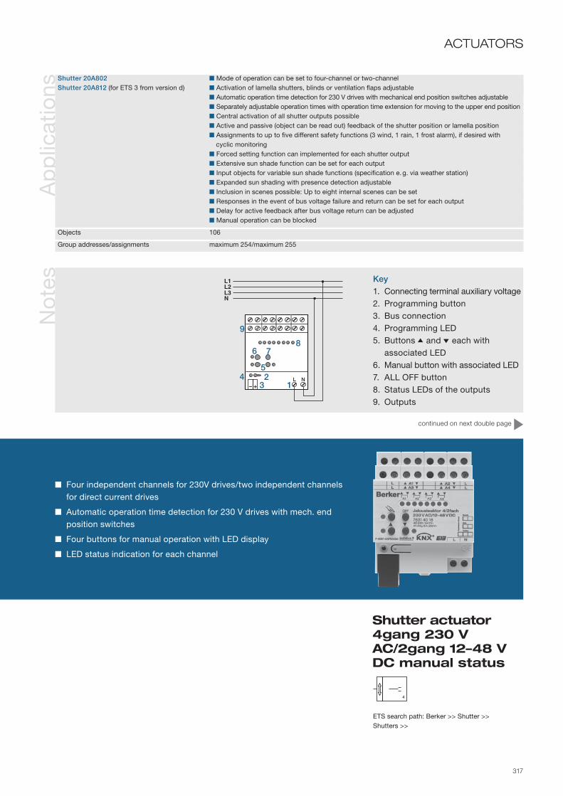
317
Ap
plic
atio
nsN
ote
s
Shutter actuator 4gang 230 V AC/2gang 12–48 V DC manual status
Four independent channels for 230V drives/two independent channels for direct current drives
Automatic operation time detection for 230 V drives with mech. end position switches
Four buttons for manual operation with LED display
LED status indication for each channel
ACTUATORS
Shutter 20A802 Mode of operation can be set to four-channel or two-channelShutter 20A812 (for ETS 3 from version d) Activation of lamella shutters, blinds or ventilation flaps adjustable Automatic operation time detection for 230 V drives with mechanical end position switches adjustable Separately adjustable operation times with operation time extension for moving to the upper end position Central activation of all shutter outputs possible Active and passive (object can be read out) feedback of the shutter position or lamella position Assignments to up to five different safety functions (3 wind, 1 rain, 1 frost alarm), if desired with
cyclic monitoring Forced setting function can implemented for each shutter output Extensive sun shade function can be set for each output Input objects for variable sun shade functions (specification e. g. via weather station) Expanded sun shading with presence detection adjustable Inclusion in scenes possible: Up to eight internal scenes can be set Responses in the event of bus voltage failure and return can be set for each output Delay for active feedback after bus voltage return can be adjusted Manual operation can be blocked
Objects 106
Group addresses/assignments maximum 254/maximum 255
ETS search path: Berker >> Shutter >> Shutters >>
Key1. Connecting terminal auxiliary voltage2. Programming button3. Bus connection4. Programming LED5. Buttons 5 and 6 each with associated LED6. Manual button with associated LED7. ALL OFF button8. Status LEDs of the outputs9. Outputs
continued on next double page
3
78
54
6
21
9

318
Info
rmat
ion
No
tes Electrical connection for 12 to 48 V drive motors
ATTENTION
A1 and A2 (as well as A3 and A4) are combined into a channel pair and control a DC drive.In 2-channel operation the manual operation for output A2 (or A4) does not have any function. The status LEDs indicate the relay states.

319
ACTUATORS(Continued)
No
tes Electrical connection for 110 to 230 V drive motors
ATTENTIONSuitable for dividing up the loads to different external phase conductors.
With appropriate programming and configuration the shutter actuator detects the operation times of the individual hangings itself and saves them. The actuator measures the voltage at the drives with mechanical end position switches the voltage against the activated N conductor, thus detecting the end positions. During operation the shutter actuator also adjusts itself to changed operation times (e. g. due to ageing of the drives).
without automatic end position detection with automatic end position detection
Shutter actuator 4gang 230 V AC/2gang 12–48 V DC manual status

320
Info
rmat
ion
The blinds actuator 4gang is designed as a top hat rail mounted device and depending on instabus KNX/EIB telegrams switches four mutually independent channels, each of which controls a motor drive. The number of channels can be reduced to two so that two motors can be activated per channel.
Using the integral manual operation on the devices it is possible to activate the individual outputs independ-ently of the bus. If a storm message is received the actuator is able to move the shutters and/or blinds into a pre-defined safety position, and to lock them there.The device requires a separate auxiliary voltage supply.
Tech
nica
l dat
a Supply via bus line 21– 32 V DC SELV Power consumption Typ. 150 mW Voltage 230 V AC ±10 %, 50/60 Hz Energy dissipation min. 0.3 to max. 1.8 W (without connected load)
Outputs Number 4 Type 1 NO and 1 change-over contact (mono stable), movement direction interlocked with each other Switching voltage 110 to 240 V AC ±10 %, 50/60 Hz Switching current max. 6 A at 230 V AC (not inductive or weakly inductive loads)
Behaviour in the event of power Bus voltage failure software-dependentfailure/restore Mains voltage failure all outputs switch off; no manual operation; Position data, functions are lost; Safety functions remain, however Bus and mains voltage failure as before - safety functions are discarded! Bus voltage restore Outputs off, bus communication possible Mains voltage return software-dependent, manual operation possible Bus and mains voltage return software-dependent, manual operation possible
Operation and display elements Button Activation of manual operation 3 push-buttons Retrievel the shutter functions locally Programming button Programming LED Red 11 status LEDs Red
Connections KNX/EIB Connecting terminal Outputs Screw terminals 0.5–4 mm² single/finely stranded without conductor sleeve 0.5 –2.5 mm² finely stranded with conductor sleeve
Protection class IP 20, EN 60529 Safety class II
Ambient temperature range Operation and storage/transport -5 to +45 °C and -25 to +70 °C
Installation/mounting orientation on top hat rail 35 mm, EN 50022 as desired
Dimensions (W x H x D) 72 x 90 x 64 mm 4 modules
Ord
er d
ata Device colour
Light grey ................ 7531 40 13
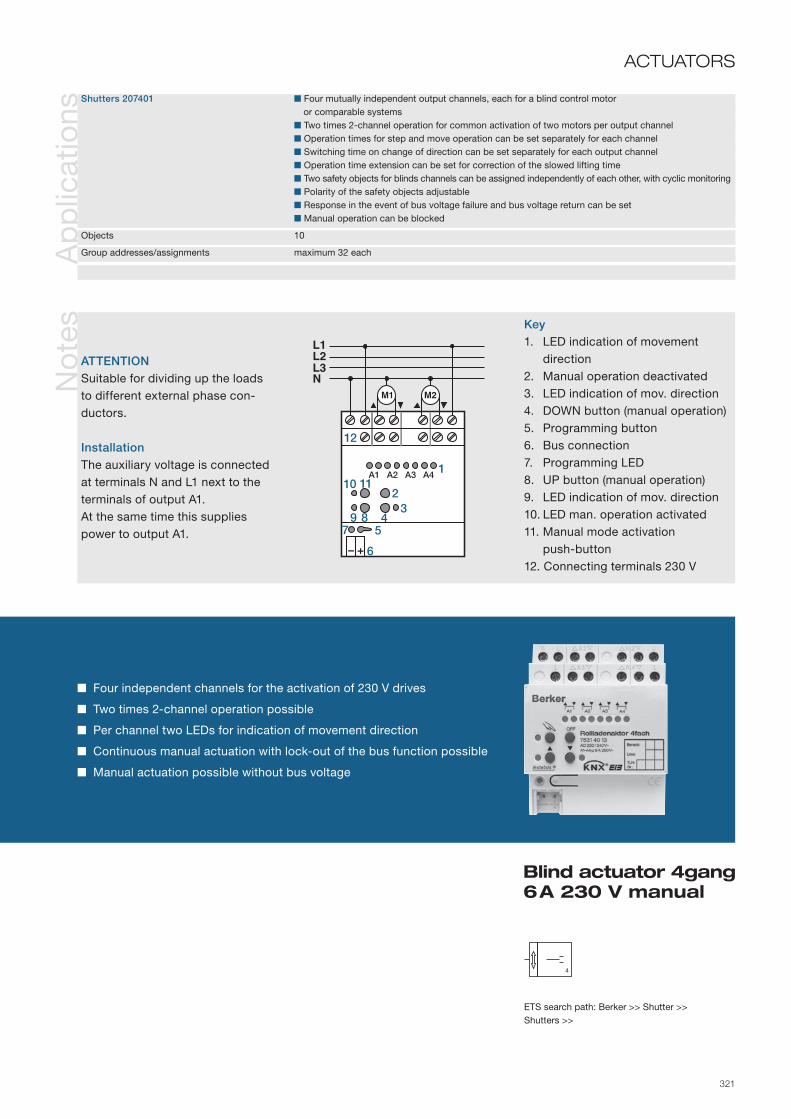
321
Four independent channels for the activation of 230 V drives
Two times 2-channel operation possible
Per channel two LEDs for indication of movement direction
Continuous manual actuation with lock-out of the bus function possible
Manual actuation possible without bus voltage
Ap
plic
atio
nsShutters 207401 Four mutually independent output channels, each for a blind control motor or comparable systems Two times 2-channel operation for common activation of two motors per output channel Operation times for step and move operation can be set separately for each channel Switching time on change of direction can be set separately for each output channel Operation time extension can be set for correction of the slowed lifting time Two safety objects for blinds channels can be assigned independently of each other, with cyclic monitoring Polarity of the safety objects adjustable Response in the event of bus voltage failure and bus voltage return can be set Manual operation can be blocked
Objects 10
Group addresses/assignments maximum 32 each
ETS search path: Berker >> Shutter >> Shutters >>
No
tes Key
1. LED indication of movement direction2. Manual operation deactivated3. LED indication of mov. direction4. DOWN button (manual operation)5. Programming button6. Bus connection7. Programming LED8. UP button (manual operation)9. LED indication of mov. direction10. LED man. operation activated11. Manual mode activation push-button12. Connecting terminals 230 V
ATTENTIONSuitable for dividing up the loads to different external phase con-ductors.
InstallationThe auxiliary voltage is connected at terminals N and L1 next to the terminals of output A1. At the same time this supplies power to output A1.
Blind actuator 4gang 6 A 230 V manual
ACTUATORS
1
32
4
6
5
12
10 11
97
8

322
Info
rmat
ion
Ord
er d
ata
The shutter actuator 4gang is designed as a rail mounted device and uses its mutually independent relay con-tacts to control motor drives for mains voltage 230 V AC (8 channels) or low voltage 12–48 V DC (4 channels).
The four push-buttons on the front of the device can be used to switch the relays on and off for manual actuation of the switching or shutter outputs in parallel with KNX/EIB, even without bus voltage or in the un-programmed state.
When the device is configured and commissioned with the ETS 3.0d or newer versions, the advantages of the new actuator generation, such as shorter download times and parameter configuration are fully usable. A separate product database is available for older ETS 2/3 versions.
A separate auxiliary voltage supply is necessary for manual operation and for the power supply for the relays.
Tech
nica
l dat
a Supply via bus line 21– 32 V DC Auxiliary voltage 110 to 230 V AC ±10 %, 50/60 Hz Total energy dissipation max. 4.5 W
Outputs Number 8/4 Dependent on the parameterised channel definition (8-channel 230 V) or (4-channel 12 – 48 V DC) Contact type μ contact, monostable Switching voltage AC 250 V~, 50/60 Hz Contact rating AC 6 A Minimum switching current AC min. 100 mA Switching voltage DC 12–48 V DC Contact rating DC 12/24 V 6 A Contact rating DC 48 V 3 A Minimum switching current DC min. 100 mA
Behaviour in the event of voltage Bus voltage failure software-dependentfailure/return Mains voltage failure Outputs switch off/stop Bus and mains voltage return software-dependent
Operation and display elements Button field 4gang Local operation 3 status LEDs, local operation red 16 Status LEDs, outputs red Programming button Programming LED red
Connections KNX/EIB Connection terminal Outputs: Screw terminals 0.5 - 4 mm² single stranded 0.35 – 4 mm² finely stranded without cond. sleeve 0.14 – 2.5 mm² finely stranded with cond. sleeve
Protection class IP 20, EN 60529
Ambient temperature range Operation -5 to +45 °C Storage/transport -25 to +70 °C
Mounting on top hat rail 35 mm EN 50022
Mounting orientation as desired preferably connection terminals at top
Dimensions (W x H x D) 144 x 90 x 70 mm 8 modules
Device colour Light grey ................ 7531 80 08

323
8
1324
6
5
9
78
Four independent channels for 230 V drives / two independent channels for direct current drives
Automatic operation time detection for 230 V drives with mechanical end position switches
Four buttons for manual operation with LED dis-play
LED status indication for each channel
Ap
plic
atio
nsShutter 20AD01 Mode of operation can be set to eight-channel or four-channelShutter 20AD11 (or ETS 3 from version d) Activation of lamella shutters, roller blinds or ventilation flaps adjustable Automatic operation time detection for 230 V AC drives with mechan. end position switches adjustable Separately adjustable operation times with operation time extension for moving to the upper end position Central activation of all shutter outputs possible Active and passive (object can be read out) feedback of the shutter position or lamella position Assignments to up to five different safety functions (3 wind, 1 rain, 1 frost alarm)
– if desired with cyclic monitoring Forced setting function can be implemented for each shutter output Extensive sun shade function can be set for each output Input objects for variable sun shade functions (specification e.g. via weather station) Expanded sun shading with presence detection adjustable Can be included in light scenes: up to eight internal scenes can be set Responses in the event of bus voltage failure and return can be set for each output Delay for active feedback after bus voltage return can be adjusted Manual operation can be blocked
Objects 160
Group addresses/assignments maximum 254/maximum 255
ETS search path: Berker >> Shutter >> Shutters >>
Info
rmat
ion Legend
1. Connecting terminal auxiliary voltage2. Programming button3. Bus connection4. Programming LED5. Buttons 5 and 6 each with associated LED6. Manual button with associated LED7. ALL OFF button8. Status LEDs of the outputs9. Outputs
NOTEWiring examples for 12 to 48 V and 110 to 230 V drive motors without or with automatic end position detec-tion can be found on pages 318/319.
Shutter actuator 8gang 230 V AC / 4gang 12 – 48 V DC, manual, status
ACTUATORSACTUATORS

324
Info
rmat
ion
Ord
er d
ata
Tech
nica
l dat
a
Device colour Light grey ................ 7534 10 04
The shutter actuator 1gang is designed as a flush-mounted device. It receives telegrams from sensors via the instabus KNX/EIB and controls a shutter or roller blind control motor with its output. Both movement directions of the actuator are interlocked with each other.
The device also has three extension unit inputs, of which inputs 1 and 2 can operate either directly on the shutter output (local operation/two push-button principle). Alternatively all of the inputs can also operate on the bus as binary inputs, e.g. for window contacts. The connected potential-free switching or push-button contacts are read in via a common reference potential on the shutter actuator. Telegrams for switching or dimming, for shutter control or value transmitter applications (dimming value transmitter, light scene extension unit) can be sent out as binary inputs.
The switch actuator is supplied by the KNX/EIB and therefore does not require any additional external power supply.
Supply via bus line 21–32 V DC
Inputs Number max. 2 Cable length 33 cm pre-assembled, max. 5 m Scanning voltage up to approx. 19 V DC; continuous signal
Output 1 1 x change-over contact plus 1 x NO, potential-free µ contacts, bistable Switching voltage 230 V AC; 50/60 Hz Switching current maximum 3 A per output Making current maximum 90 A (200 μs) maximum 80 A (1ms) Switching power maximum 1 motor 600 VA Minimum switching current 100 mA
Behaviour in the event of Outputs Dependent on parameterisationbus voltage failure Inputs No response
Behaviour in the event of Outputs Dependent on parameterisationbus voltage return Inputs Dependent on parameterisation
Operation and display elements Programming button Programming LED red
Connections KNX/EIB pre-assem. connecting cable, connecting terminal Inputs pre-assem. connecting cable: YY 6 x 0.6 mm Output pre-assem. connecting cable: 3 x H05 V-K 1.5 mm2
with conductor sleeves
Protection class IP 20, EN 60529
Ambient temperature range Operation -5 to +45 °C Storage/transport -25 to +70 °C
Mounting e. g. insertion in deep flush-mounted box Ø 60 mm x 60 mm
Mounting orientation as desired
Dimensions (Ø x H) 53 x 28 mm
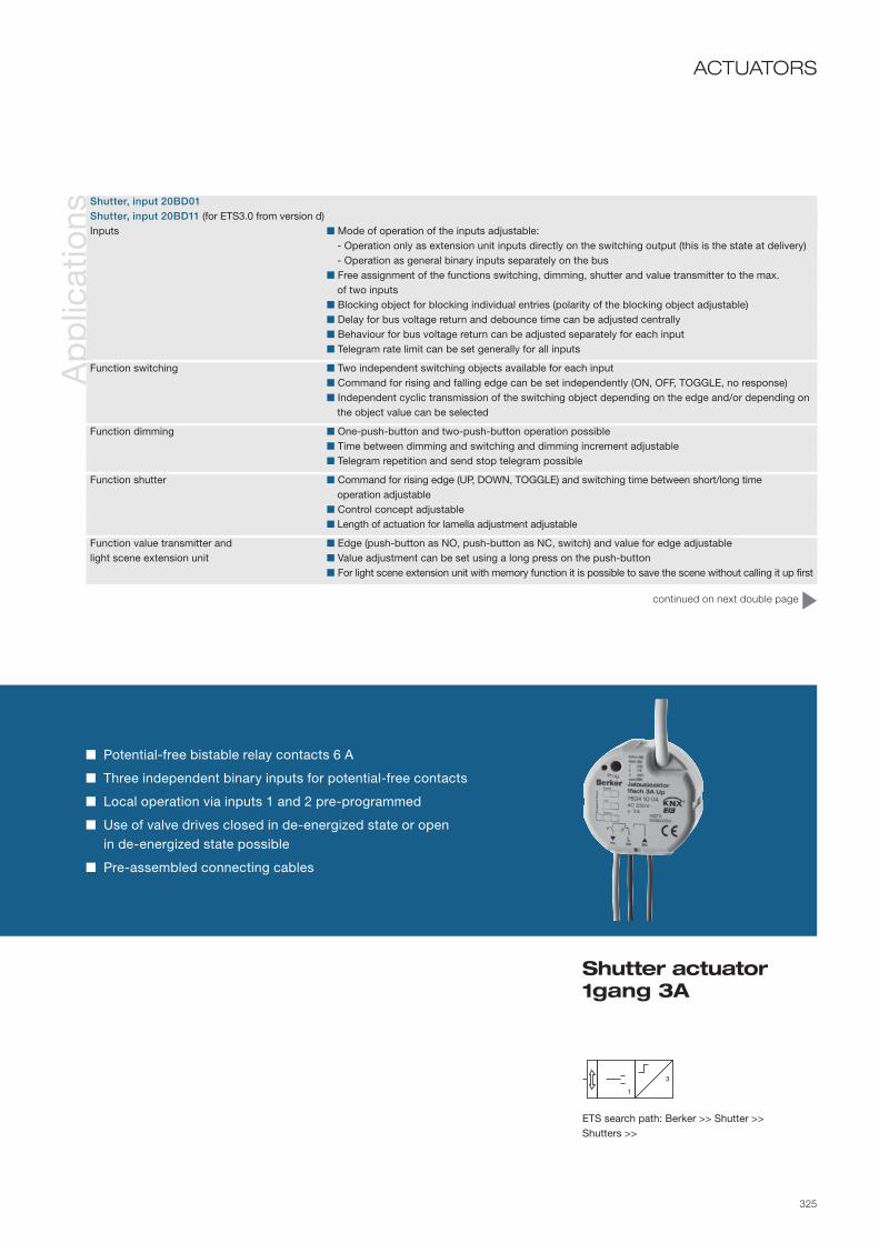
325
Ap
plic
atio
ns
Shutter actuator 1gang 3A
ACTUATORS
Potential-free bistable relay contacts 6 A
Three independent binary inputs for potential-free contacts
Local operation via inputs 1 and 2 pre-programmed
Use of valve drives closed in de-energized state or open in de-energized state possible
Pre-assembled connecting cables
ETS search path: Berker >> Shutter >> Shutters >>
Shutter, input 20BD01 Shutter, input 20BD11 (for ETS3.0 from version d)Inputs Mode of operation of the inputs adjustable: - Operation only as extension unit inputs directly on the switching output (this is the state at delivery) - Operation as general binary inputs separately on the bus Free assignment of the functions switching, dimming, shutter and value transmitter to the max. of two inputs Blocking object for blocking individual entries (polarity of the blocking object adjustable) Delay for bus voltage return and debounce time can be adjusted centrally Behaviour for bus voltage return can be adjusted separately for each input Telegram rate limit can be set generally for all inputs
Function switching Two independent switching objects available for each input Command for rising and falling edge can be set independently (ON, OFF, TOGGLE, no response) Independent cyclic transmission of the switching object depending on the edge and/or depending on
the object value can be selected
Function dimming One-push-button and two-push-button operation possible Time between dimming and switching and dimming increment adjustable Telegram repetition and send stop telegram possible
Function shutter Command for rising edge (UP, DOWN, TOGGLE) and switching time between short/long time operation adjustable Control concept adjustable Length of actuation for lamella adjustment adjustable
Function value transmitter and Edge (push-button as NO, push-button as NC, switch) and value for edge adjustablelight scene extension unit Value adjustment can be set using a long press on the push-button For light scene extension unit with memory function it is possible to save the scene without calling it up first
continued on next double page
3

326
Info
rmat
ion
Ap
plic
atio
ns
Shutter, input 20BD11 (continued)Output Operating mode can be set (shutter, roller blind, or ventilation flap) Separately adjustable shutter operation times with independently adjustable lamella operation times Switching time on change of direction and times for short/long time operation adjustable Feedback of the shutter position or lamella position with active feedback function (when changed or cyclically transmitting to the bus) or passive feedback function (object can be read out) Assignments to up to 5 different safety functions (1 rain, 1 frost, 3 wind alarms), if desired with cyclic monitoring Extensive sun shade function with expanded sun shading for integration into more complex shading control systems (has separate automatic and blocking objects), if desired with automatic heating-cooling and presence function Forced setting function adjustable Up to 8 internal scenes adjustable Response after bus voltage failure and return adjustable
Objects 28
Group addresses/assignment maximum 254/maximum 255

327
ACTUATORS(Continued)
Shutter actuator 1gang 3A
Info
rmat
ion NOTE
The connection of 230 V signals or other external voltages to the extension unit inputs is not per-missible!
Minimum distance between bus/extension unit cores and mains voltage cores 4 mm.
Recommendation: Install the switch actuator in two interconnected flush-mounted boxes (see illustration at right). One box (10) can house the bus and extension unit connection and also a series switch (11), for example.
The other box (8) houses the the switch actuator and the 230 V terminals. The 6pole connecting cable (9) is routed through the connection between the boxes.
Legend1. KNX/EIB connection (red/black)2. Input 1 (green)3. Input 2 (white)4. Input 3 (yellow)5. Reference potential com (brown)6. Programming button7. Programming LED8. Flush-mounted box for window
interface9. 6pole connecting cable
10. Flush-mounted box for series switch, etc.
11. Series switch
green
black
red
white
yellow
brown 5
67
4
23
18
9
10
11
Connection diagram e.g. for a series switch

328
Info
rmat
ion
Ord
er d
ata
The room actuator 4/2gang is designed as a rail mounted device, and is used for activation of electrical loads from various building facilities, such as those found in residential or office spaces or in a hotel room.
The first 4 outputs can be set to shutter operation, or alternatively to switching operation; mixed operation of these two operating modes is also possible on the device. By means of two additional electronic switching outputs the actuator can control electrothermal valve drives for heating or cooling systems. Up to 4 elec-trothermal valve drives can be connected to each of these electronic outputs, which are protected against overload and short-circuit.
Tech
nica
l dat
a Supply via bus line 21– 32 V DC Auxiliary voltage 110 to 230 V AC ±10 %, 50/60 Hz Total energy dissipation max. 6 W
Outputs Number 6
Outputs A1 – A4 potential-free NO contacts μ contacts, bistable Switching voltage 250 V AC Contact rating AC1/AC3 (cos ϕ < 0.8) 16 A /6 A Making current max. 800 A, 200 μs; max. 165 A 20 ms min. switching current 100 mA Switching capacities 3,000 W (ohmic) 16 A, max. 140 μF (capacitive) 1,380 VA (shutter/roller blinds or fan motors)
Outputs A5 – A6 Semiconductor (triac) ε Switching voltage 230 V AC Switching current 5 – 50 mA Making current 2 s max. 1.5 A Number of drives per output max. 4
Behaviour in the event of voltage Bus voltage failure software-dependentfailure/return Mains voltage failure Outputs switch off/stop Bus and mains voltage return software-dependent
continued on next double page
continued on next double page Device colour Light grey ................ 7531 40 19

329
Four independent channels for switching loads / two independent chan-nels for 230V drives
Mixed operation for switching and shutter applications
Two additional electronic switching outputs for heating control
Noiseless activation of up to 4 thermoelectric drives per electronic output
Four push-buttons with LED display for manual operation
LED status indication for each channel
Ap
plic
atio
nsSwitching, shutter, valve 20B301 Shutter or switching operation can be set for outputs A1... A4 Conversion of switching or constant command value telegrams on the electronic outputs Switching, shutter, valve 20B311 can be set in a switching or pulse-width modulated output signal(for ETS 3 from version d) Separate status feedback to the bus for manual operation; manual operation can be blocked via the
bus
Shutter operation Activation of lamella shutters, roller blinds or ventilation flaps adjustable Separately adjustable operation times with operation times extension for moving to the upper end
position Central activation of all shutter outputs possible Active and passive (object can be read out) feedback of the shutter position or lamella position Assignments to up to five different safety functions (3 wind, 1 rain, 1 frost alarm), if desired with cyclic
monitoring Forced setting function can be implemented for each shutter output Extensive sun shade function can be set for each output Can be included in light scenes, up to eight internal scenes can be set
Switching operation NO or NC operation can be set Central switching function with group feedback Active and passive (object can be read out) feedback of the switching state Logical linking function ("AND", "OR", "AND with return") for each output Blocking function parameterisable for each channel – alternatively forced setting function for each
output Time functions (switch-on, switch-off delay, stair light function - also with pre-warning function) Can be included in light scenes, up to eight internal scenes can be set
Valve activation Activation via a switching (1-bit) or continuous (1-byte) command value telegram adjustable. Status feedback (1-bit or 1-byte) automatic or upon read request adjustable Valve direction of action (open/closed in de-energized state) adjustable Summer or winter can be selected via an object (polarity configurable) Cyclical monitoring of the command value adjustable, emergency operation and alarm message can
be transmitted to the bus via a separate object (polarity parameterisable) Forced position for activation of a valve position with fixed parameterisation in the ETS Short-circuit and overload protection with optional separate alarm message to the bus (polarity
adjustable) Anti-sticking protection for the connected valve drives
Objects 72
Group addresses/assignments maximum 254/maximum 255
ETS search path: Berker >> Output >> Binary output, mix >>Berker >> Heating, air conditioning, ventilation >> Valve >>
6
Room actuator 4/2gang 16 A NO con-tact, manual, status
ACTUATORS

330
Info
rmat
ion
Tech
nica
l dat
a Operation and display elements Button field 4gang Local operation 3 status LEDs, local operation red 6 Status LEDs, outputs red Programming button Programming LED red
Connections KNX/EIB Connection terminal Outputs: Screw terminals 0.5 - 4 mm² single stranded 0.35 – 4 mm² finely stranded without cond. sleeve 0.14 – 2.5 mm² finely stranded with cond. sleeve
Protection class IP 20, EN 60529
Ambient temperature range Operation -5 to +45 °C Storage/transport -25 to +70 °C
Mounting on top hat rail 35 mm EN 50022
Mounting orientation as desired preferably connection terminals at top
Dimensions (W x H x D) 70 x 90 x 70 mm 4 modules
The four push-buttons on the front of the device can be used to switch the relays on and off for manual actuation of the switching or shutter outputs in parallel with KNX/EIB, even without bus voltage or in the un-programmed state.
A separate auxiliary voltage supply is necessary for manual operation and for the power supply for the relays.

331
ACTUATORS(Continued)
Info
rmat
ion Legend
1. Connecting terminal auxiliary voltage
2. Programming button3. Bus connection4. Programming LED5. Buttons 5 and 6 each with associated LED6. Manual button with associated
LED7. ALL OFF button8. Status LEDs of the outputs9. Outputs
10. Connection for 230 V electro-thermal drives
NOTESuitable for switching different ex-ternal phase conductors. The connection of mains voltage and SELV/PELV electric circuits to a switch actuator is not permitted. The connection of three-phase mot-ors is not permitted. Do not connect more than four electrothermal valve drives per electronic switching output. Do not connect any electric motor-driven valve drives! The neutral conductor terminals (labelled "N") next to the electronic switching outputs are intended exclusively as a connection aid for the neutral conductors of the valve drives. The terminals are not connected in the room actuator with any voltage potential or with any other connec-ting terminal (free supporting termi-nals), and their use is therefore optional (see 10).
10
L1L2L3N
+–
M1
1324
6
5
9
78
L1L2L3N
+–
Room actuator 4/2gang 16 A NO con-tact, manual, status

332
Info
rmat
ion
Ord
er d
ata
The fan coil actuator 2gang is designed as a rail mounted device, and allows the control of one or two fan coil units for the heating and cooling of rooms. The device can be used for fan coil units for 2- or 4-tube systems.
The fan coil actuator receives command value telegrams and converts these command value telegrams into equivalent fan stages. Furthermore, the fan coil actuator activates the valves in the fan coil unit, which open or close the heating or cooling tube(s) in accordance with the demand. In addition, the fan coil actuator also allows manual activation of the fan, allowing execution of simple ventilation functions without heating or cool-ing operation, or individual room ventilation when heating or cooling are active. This function is of interest for hotel rooms, classrooms or office spaces, for example. Manual control can be performed using push-buttons or operating panels.
Tech
nica
l dat
a Supply via bus line 21– 32 V DC Auxiliary voltage 230/240 V AC, 50/60 Hz Total energy dissipation max. 3 W
Outputs potential-free NO contacts μ contacts, bistable Switching voltage 230 V AC Contact rating AC1/AC3 (cos ϕ < 0.65) 10 A /10 A Making current max. 800 A, 200 μs; max. 165 A 20 ms min. switching current 100 mA Switching capacities 2,300 W (ohmic) 10 A, max. 140 μF (capacitive) 2,300 W (230 V incandescent/halogen lamps) 1,500 W (electronic transformers) 1,200 VA (inductive transformers)
Behaviour in the event of voltage Bus voltage failure software-dependentfailure/return Mains voltage failure Outputs switch off Bus and mains voltage return software-dependent
Operation and display elements Button field 4gang Local operation 3 status LEDs, local operation red 8 Status LEDs, outputs red Programming button Programming LED red
Connections KNX/EIB Connection terminal Outputs: Screw terminals 0.5 - 4 mm² single stranded 0.35 – 4 mm² finely stranded without cond. sleeve 0.14 – 2.5 mm² finely stranded with cond. sleeve
Protection class IP 20, EN 60529
Ambient temperature range Operation -5 to +45 °C Storage/transport -25 to +70 °C
Mounting on top hat rail 35 mm EN 50022
Mounting orientation as desired preferably connection terminals at top
Dimensions (W x H x D) 72 x 90 x 70 mm 4 modules
continued on next double page Device colour Light grey ................ 7531 20 12

333
Activation of one or two fan coils
Activation of one or two fan channels with six or three fan stages for the operating modes heating, cooling, heating and cooling
Use of free channels to control switching loads
Four push-buttons with LED display for manual operation
Ap
plic
atio
ns
Switching, fan coil 20B001 1-channel operation or alternatively 2-channel operation can be set 5 different fan coil systems can be controlled:Switching, fan coil 20B011 - 2-tube system only heating (1- and 2-channel operation)(for ETS 3 from version d) - 2-tube system only cooling (1- and 2-channel operation) - 2-tube system heating/cooling via change-over object (1- and 2-channel operation) - 4-tube system heating/cooling via change-over object (only 1-channel operation) - 4-tube system heating/cooling via command value specification (only 1-channel operation) Separate status feedback to the bus for manual operation; manual operation can be blocked via the
bus Responses in the event of bus voltage failure and bus and mains voltage return can be set Read request possible for operating mode switching in case of switching via object Valve and fan protection configurable Number of fan stages can be set in the ETS (1-channel operation max. 6 fan stages, 2-channel opera-
tion max. 3 fan stages each) Fan stages can be operated per alternating principle (only one fan stage output switches on) or stages
principle (fan stage outputs switch hierarchically) Command value ranges for the fan stages can be adjusted flexibly through assignment of a command
value (1 to 100 %) for each fan stage incl. hysteresis Switch on behaviour of the fan adjustable Switch on delay of the fan during heating or switch-off delay during cooling adjustable Limitation of the fan stage via separate 1-bit object to activate Feedback of the active fan stage either as an active Feedback of the active fan stage either as active message object (transmitting when there is an
update) or as a passive status object (can be read out) Manual fan control possible Cyclic monitoring of the command value telegrams adjustable Blocking function possible Behaviour of the outputs at the beginning and end of the block adjustable
Objects 45
Group addresses/assignments maximum 254/maximum 255
ETS search path: Berker >> Heating, air conditioning, ventilation >> Fan coil >>
8
Fan coil actuator 2gang 10 A NO contact, manual, status
ACTUATORS

334
Info
rmat
ion
The four push-buttons on the front of the device can be used to switch the relays on and off for manual actuation of the connected valves/fans in parallel with KNX/EIB, even without bus voltage or in the unpro-grammed state.
A separate auxiliary voltage supply is necessary for manual operation and activation of the outputs.
Info
rmat
ionElectrical connection in 1-channel operation
4-tube fan coil system (heating and cooling via separate valve) with 3 fan stages
In 1-channel operation the outputs A1 to maximum A8 form the valve and fan stage outputs. In the example output 8 is not used as a fan stage, and is wired as a simple switching output (B). Outputs A6 and A7 are not used in the connection example.
Electrical connection in 2-channel operation2-tube fan coil system (heating and cooling via separate valve) with 3 fan stages
In 2-channel operation the outputs A1 to A4 form the valve and fan stage outputs for channel 1, and outputs A5 to A8 the valve and fan stage outputs for channel 2.
L1L2L3N
L1L2L3N
A1 … A4
A5 … A8
B
A5 … A8
A1 … A4
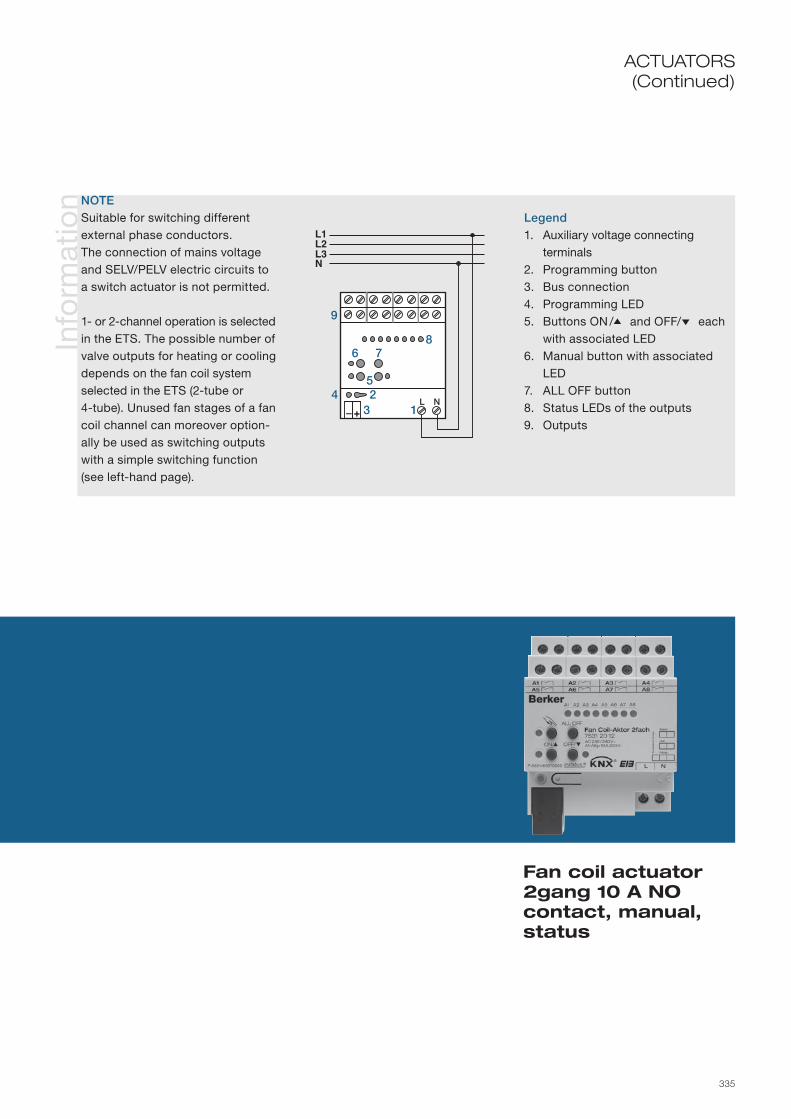
335
ACTUATORS(Continued)
Info
rmat
ion
Legend1. Auxiliary voltage connecting
terminals2. Programming button3. Bus connection4. Programming LED5. Buttons ON /5 and OFF/6 each
with associated LED6. Manual button with associated
LED7. ALL OFF button8. Status LEDs of the outputs9. Outputs
NOTESuitable for switching different external phase conductors.The connection of mains voltage and SELV/PELV electric circuits to a switch actuator is not permitted.
1- or 2-channel operation is selected in the ETS. The possible number of valve outputs for heating or cooling depends on the fan coil system selected in the ETS (2-tube or 4-tube). Unused fan stages of a fan coil channel can moreover option-ally be used as switching outputs with a simple switching function (see left-hand page).
L1L2L3N
+– 1324
6
5
9
78
Fan coil actuator 2gang 10 A NO contact, manual, status

336
Info
rmat
ion
Ord
er d
ata
The window interface 1gang is designed as a flush-mounted device. It receives telegrams from sensors via the instabus KNX/EIB and uses its combined outputs to control two systems, such as those typically present in the area of windows. Thus they can activate a shutter or roller blind motor, and up to two thermoelectric valve drives with one electronic output.
The device also has three extension unit inputs, of which inputs 1 and 2 can operate either directly on the shutter output (local operation/two push-button principle). Alternatively all of the inputs can also operate on the bus as binary inputs, e.g. for window contacts. The connected potential-free switching or push-button contacts are read in via a common reference potential on the shutter actuator. Telegrams for switching or dimming, for shutter control or value transmitter applications (dimming value transmitter, light scene extension unit) can be sent out as binary inputs.
The device is supplied by the instabus KNX/EIB and therefore does not require any additional external power supply.
Tech
nica
l dat
a Supply via bus line 21– 32 V DC
Inputs Number max. 3 Cable length 33 cm pre-assembled, max. 5 m Scanning voltage up to approx. 19 V DC; continuous signal
Motor output 1 x change-over plus 1 x NO potential-free μ contacts, bistable Switching voltage 230 V AC, 50/60 Hz Switching current maximum 3 A per output Making current maximum 90 A (200 μs) maximum 80 A (1ms) Switching power maximum 1 motor 600 VA Minimum switching current 100 mA
Heating output Semiconductor (triac) ε Switching voltage 230 V AC, 50/60 Hz Switching current 5 to 25 mA Making current maximum 600 mA (2 s) Number of drives per output maximum 2
Behaviour in the event of bus voltage Outputs Dependent on specific parameterisationfailure/return Inputs No response/dependent on parameterisation
Operation and display elements programming button Programming LED red
Connections KNX/EIB Preassem. connecting cable: connecting terminal Inputs Preassem. connecting cable: YY 6 x 0.6 mm Output Preassem. connect. cable: 4 x H05 V-K 1.5 mm² Connecting terminals included
Protection class IP 20, EN 60529
Ambient temperature range Operation -5 to +45 °C Storage/transport -25 to +70 °C
Mounting e.g. insertion in deep flush-mounted box Ø 60 mm x 60 mm
Mounting orientation as desired
Dimensions (W x H x D) 53 x 28 mm
Device colour Light grey ................ 7534 10 06

337
Potential-free, bistable relay contacts 3 A for motor control
Electronic output for up to 2 thermoelectric drives
Three independent binary inputs for potential-free contacts
Local operation for motors via inputs 1 and 2 pre-programmed
Use of valve drives closed in de-energized state or open in de-energized state possible
Pre-assembled connecting cables
Ap
plic
atio
ns
Shutter, valve, input 20BA01Shutter, valve, input 20BA11 (for ETS3.0 from version d)
Inputs Mode of operation of the inputs adjustable: - Operation only as extension unit inputs directly on the switching output (state at delivery) - Operation as general binary inputs separately on the bus Free assignment of the functions switching, dimming, shutter and value transmitter to the max. of
two inputs Blocking object for blocking individual entries (polarity of the blocking object adjustable) Delay for bus voltage return and debounce time can be adjusted centrally Behaviour for bus voltage return can be adjusted separately for each input Telegram rate limit can be set generally for all inputs
Function switching Two independent switching objects available for each input Command for rising and falling edge can be set independently (ON, OFF, TOGGLE, no response) Independent cyclic transmission of the switching object depending on the edge and/or depending on
the object value can be selected
Function dimming One-push-button and two-push-button operation possible Time between dimming and switching and dimming increment adjustable Telegram repetition and send stop telegram possible
Function shutter Command for rising edge (UP, DOWN, TOGGLE) and switching time between short/long time operation adjustable
Control concept adjustable Length of actuation for lamella adjustment adjustable
Function value transmitter and Edge (push-button as NO, push-button as NC, switch) and value for edge adjustablelight scene extension unit Value adjustment can be set using a long press on the push-button For light scene extension unit with memory function it is possible to save the scene without calling it up
first
Motor output see shutter actuator 1gang 3 A flush-mounted (7534 10 04)
Heating output see heating actuator 1gang 230 V AC flush-mounted (7534 10 05)
Objects 36
Group addresses/assignments maximum 254/maximum 255
ETS search path: Berker >> Output >> Binary output, mix >>Berker >> Shutter >> Shutters >>Berker >> Heating, air conditioning, ventilation >> Valve >>
1 1 3
Window interface 1/1gang
ACTUATORS

338
Info
rmat
ion

339
ACTUATORS(Continued)
Info
rmat
ion
green
black
red
white
yellow
brown 5
67
4
23
18
9
10
11
Window interface 1/1gang
NOTEThe connection of 230 V signals or other external voltages to the extension unit inputs is not per-missible!
Minimum distance between bus/extension unit cores and mains voltage cores 4 mm.
Recommendation: Install the switch actuator in two interconnected flush-mounted boxes (see illustration at right). One box (10) can house the bus and extension unit connection and also a series switch (11), for example.
The other box (8) houses the the switch actuator and the 230 V terminals. The 6pole connecting cable (9) is routed through the connection between the boxes.
Legend1. KNX/EIB connection (red/black)2. Input 1 (green)3. Input 2 (white)4. Input 3 (yellow)5. Reference potential com (brown)6. Programming button7. Programming LED8. Flush-mounted box for window
interface9. 6pole connecting cable
10. Flush-mounted box for series switch, etc.
11. Series switch
Connection diagram e.g. for a series switch

340
Info
rmat
ion
Ord
er d
ata
Tech
nica
l dat
a
Device colour Light grey ................ 7551 40 01
The analogue actuator 4gang is designed as a top hat rail mounted device and has four analogue outputs that can output voltage or current signals. For this purpose the device converts measurement data that is received via KNX/EIB telegrams into analogue output signals. The analogue output signals make it possible for end devices of the heating, air conditioning and ventilation systems to adapt their output variables based on bus information and to take part in control processes. Outputs that are not needed can be switched off.
For operation the analogue output requires a 24 V auxiliary voltage. The lateral interface can be used to connect an analogue actuator module for another four analogue outputs, which are likewise adjusted via the software of the basic unit.
Supply via bus line 21– 32 V DC
Auxiliary voltage 24 V AC ±10 % SELV Current input maximum 310 mA
Outputs Current or voltage output 4 Signal type Depending on setting: 0–1 V DC, 0–10 V DC, 0–20 mA DC or 4–20 mA DC Load output signal Voltage signal, ≥ 1 kohm Current signal, ≤ 500 ohm Output current Voltage signal, maximum 10 mA per channel Current signal, maximum 20 mA per channel
Behaviour in the event of power failure Bus voltage failure adjustable: last value is kept Supply voltage failure Outputs run against 0 V or 0 mA
Behaviour in the event of power return Bus voltage adjustable: no response Initialisation state, last value before failure Supply voltage Adjustable status query of the group addresses, Detection and adjustment of the set output states when bus voltage is connected
Operation and display elements Programming key Programming LED Red Status LED Red/orange/green 4 status LED outputs yellow
Connections KNX/EIB Connecting terminal Outputs 0.5–4 mm² single-core 0.34–4 mm² single-core/finely stranded without conductor sleeve, 0.14–2.5 mm² finely stranded with conductor sleeve Module connection 6pole. System plug for analogue output module
Protection IP 20, EN 60529
Ambient temperature range Operation -5 to +45 °C Storage/transport -25 to +70 °C
Dimensions (W x H x D) 72 x 90 x 58 mm 4 modules
AccessoriesAnalogue output module ....................
Power supply 24 V AC ...................
7552 40 01
7591 00 01

341
Ap
plic
atio
nsN
ote
s
Analogue actuator 4gang
ACTUATORS
Four freely adjustable outputs
Conversion of digital measurement data into voltage or current signals
LED status indication for each channel
Four additional outputs possible using analogue actuator module
System interface for connection of an analogue output module
Analogue actuator B00811Analogue outputs Type of signal output (0 –10 V, 0–1 V, 0–20 mA, 4–20 mA) adjustable Format of the input value (8-bit or 16-bit) adjustable Dim actuator operation (for 8-bit input objects) possible Output value after initialisation adjustable Up to two forced guidance functions possible Cyclic monitoring of the input variables Response for exceeding of the monitoring time can be set Behaviour in the event of bus voltage failure and bus voltage return can be set
Modules One analogue actuator module with four additional inputs can be selected: Programming options are the same as the basic unit
Objects 58
Group addresses/assignments maximum 200 each
ETS search path: Berker >> Output >> Analogue output, 4gang >>
Key1. Analogue actuator module connection 2. Bus connection 3. Programming button 4. Programming LED 5. Status LED6. Status LED outputs7. Device with analogue interface
TerminalsGND: Reference potential for outputsA1 to A4: OutputsAC 24 V: External supply voltage 1
3
2
4
65
7

342
Info
rmat
ion
Tech
nica
l dat
a Auxiliary voltage 24 V AC ±10 % SELV Current input maximum 310 mA
Outputs Current or voltage output 4 Signal type Depending on setting: 0–1 V DC, 0–10 V DC, 0–20 mA DC or 4–20 mA DC Load output signal Voltage signal, ≥ 1 kohm Current signal, ≤ 500 ohm Output current Voltage signal, maximum 10 mA per channel Current signal, maximum 20 mA per channel
Behaviour in the event Bus voltage failure adjustable: last value is keptof power failure Supply voltage failure Outputs run against 0 V or 0 mA
Behaviour in the event of power return Bus voltage adjustable: no response Initialisation state, last value before failure Supply voltage Adjustable status query of the group addresses, Detection and adjustment of the set output states when bus voltage is connected
Operation and display elements Status LED Red /orange/green 4 status LED outputs Yellow
Connections Actuator connection 6pole system plug Outputs 0.5–4 mm² single-core 0.34–4 mm² single-core/finely stranded without conductor sleeve, 0.14 –2.5 mm² finely stranded with conductor sleeve
Protection class IP 20, EN 60529
Ambient temperature range Operation -5 to +45 °C Storage/transport -25 to +70 °C
Dimensions (W x H x D) 72 x 90 x 58 mm 4 modules
The analogue actuator module is an inexpensive way to expand the analogue actuator 4gang to include four additional outputs for voltage or current signals.
No separate application is available for the device; programming is carried out via the software of the basic unit.
For operation the analogue input of the module requires a 24 V auxiliary voltage that is made available either directly from the 24V AC power supply or indirectly via the 24 V AC terminals of the basic unit.
Ord
er d
ata Device colour
Light grey ................ 7552 40 01AccessoriesPower supply 24 V AC ................... 7591 00 01

343
Four additional analogue outputs
Link to basic unit via 6pole system interface
Status LED for indicating readiness for operation
LED status indication for each channel
Analogue actuator module 4gang
ACTUATORSN
ote
s
Key1. Device with analogue interface2. 6pole system plug, e. g. for con- nection of an analogue actuator 3. Status LED outputs4. Status LED5. Analogue actuator 7551 40 01
TerminalsGND: Reference potential for outputsA1 to A4: OutputsAC 24 V: External supply voltage
InstallationConnection of the analogue actua-tor module is exclusively by means of the 6pole system plug. Only one analogue actuator module can be connected per basic unit.
The GND connections of the ana-logue actuator module may not be connected to the corresponding connections of another device, e. g. of the analogue input. The exchange of an analogue actuator module in the event of a defect can be carried out in ongoing operation (isolate module from voltage!).
Then the analogue actuator carries out a reset after approx. 25 seconds. This re-initialises all inputs and places them in the original state.
15
2
4 3

344
Info
rmat
ion
Ord
er d
ata
The valve drive is suitable for mounting on Heimeier thermostat valve lower parts for room temperature control such as on heaters, radiators, convectors, heating circuit distributors for underfloor heating systems, etc. It is maintenance-free and designed for direct connection to the instabus KNX/EIB.
The valve drive moves the heating valve to the appropriate position according to the setpoint (target) value transmitted by a KNX/EIB room thermostat.
Window contacts, for example, as well as normal push-buttons and switches can be connected by way of 2 potential-free inputs. They can act directly on the actuator or be used for switching, dimming or shutter control.
The valve drive has no programming button, but has a reed contact which is operated by a programming magnet (separate order number). The programming function is toggled on and off when the reed contact is only approached.
Device colourValve drive with 2 inputsWhite .......................
Programming magnetWhite .......................
7550 00 02
7590 00 19
Tech
nica
l dat
a Supply via bus line 21–32 V DC
Inputs Number 2 Signal voltage 20 V pulses, approx. 3 ms long Signal current approx. 1 mA per channel Length of input cable max. 5 m
Output 1 channel Controls one thermostat valve tappet Stroke max. 4.2 mm Running time 25 s/mm
Response to bus power Bus power failure Drive remains in last positionfailure/restore Mains power failure - Bus and mains power failure - Bus power restoration Drive runs through adjustment routine. Then the “Manipulated variable if no controller is present...” value is activated and manipulated variable telegrams are waited for. Inputs are interrogated and the programmed function is triggered if necessary. Mains power restoration - Bus and mains power restoration -
Operating and display elements Reed contact for triggering the programming Activation via programming magnet Programming button Programming LED Red
Connections KNX/EIB Terminal via pre-manufactured connecting cable (J)EYY–OB 3 x 2 x 0.6/1m
Protection IP 43; EN 60529 Note mounting orientation
Ambient temperature range Operation 0 to +50 °C Storage/transport -20 to +70 °C
Mounting Bolted on to thermostat valve tappet
Mounting orientation Vertical upright IP 43 other positions IP 42
Dimensions (W×H×D) 46 x 87 x 60 mm

345
Direct connection to instabus KNX/EIB
Control of devices for room temperature regulation
High control accuracy based on proportional translation of adjustment travel
Maintenance-free
2 potential free inputs for window contacts
ACTUATORSA
pp
licat
ions
Valve drive A00D01 2 binary inputs to control valve drive or generate switch, dim or shutter commands Reception of a valve manipulated variable signal (e.g. from a thermostat) Change in heater valve tappets (0 to 255 = 0 to 100 %) dependent on manipulated variables (proportional to a setting between “Open” and “Closed”) Complete change of position of valve when telegram evaluation sustained Execution of last telegram Minimum change of manipulated variable: ±2 degrees of manipulation (range 0 to 255)
Maximum travel of servo drive approx. 4.2 mm Variable travel of connected heater valve tappets (possibly less) Adjustment routine – facility to ascertain actual adjustment travel Proportional conversion of adjustment travel (possibly differing from travel of valve drive) Initialization of adjustment routine after – download/restoration of bus power or – 4096 “manipulated variable” telegrams received (object update) or – 4096 actual adjustments of the heater valve
Objects 12
Group addresses/assignments maximum 12
ETS search path: Berker >> Heating, air conditioning >> Valves >>
Valve drive
No
tes
M
2
InstallationPlease avoid mounting vertically underneath the valve lower part (with knurled nut at top), since water may then get into the device in the event of a leak. The servo drive is mounted by pressing it lightly onto the heater valve, and the union nut is tightened using a suitably sized pair of pliers.
ProgrammingSwitching the programming function on and off is achieved by bringing the programming magnet close to the activation point (toggle function).
Key1. Union nut2. Bus connection (Bus/binary input)3. Programming LED4. Activation point for the programming magnet
1
2
3
4

346
Info
rmat
ion
Ord
er d
ata
The heating actuator 6gang is executed as a top hat rail-mounted device for activation of electro-thermal actuator drives (ETA) for heating systems or cooling systems. It has 6 electronic outputs, which are silently activated by KNX/EIB telegrams. Up to four actuator drives (e.g. order no. 7590 00 71) can be connected to each output.
Outputs provide either switching or a PWM signal, depending on the setting of the control variable (1 bit or 8 bit). In the unprogrammed condition the heating actuator is set for pulse width modulation with a control variable of 50 % and a cycle time of 15 minutes. This permits the actuator to be tested for functioning even without bus power.
The heating actuator is able to detect overloads/short circuits at an output/at multiple outputs.
Device colourLight grey ................ 7531 60 03
Tech
nica
l dat
a Supply via bus line 21–32 V DC Power consumption typically 125 mW
Power supply 230 V AC ±10 %, 50/60 Hz Power loss approx. 2 W disregarding the power loss of the actuator drives (depending on the type and number of the actuator drives)
Outputs 6 Triac Rated voltage 230 V AC ±10 %, 50/60 Hz (dependent on the mains input voltage) Rated current 50 mA (resistive per output) Making current max. 1.5 A (short-time) Minimum load 2 W (1 actuator drive) Number of connectable loads max. 4 actuator drives per output (actuator drives can be from different manufacturers)
Actuator drives 230 V electro-thermal per output max. 4
Behaviour on power Bus power failure Software-dependentfailure/restore Mains power failure all outputs deactivated (outputs high-resistance), Bus communication exists; Control variables received will be acted upon Bus and mains power failure all outputs deactivated (outputs high-resistance) Bus power restoration Software-dependent Mains power restoration PWM 50 % (15 minutes cycle time) Bus and mains power restoration - Programmed actuator: Software-dependent - Unprogrammed actuator: PWM 50 % (15 minutes cycle time)
Operation and display elements Programming button Programming LED Red
Continued on next double page
Continued on next double page

347
8
Six independent electronic outputs
Up to four electro-thermal actuator drives can be connected to each output
Choice between switching and continuous (PWM) regulation
Detection and reporting of overloads or short circuits
Changeover between summer and winter mode by object
Back-up operation in the event ofsensor or bus failure
Automatic valve protection
Heating actuator 6gang Triac 230 V AC
ACTUATORSA
pp
licat
ions
Switching PWM 206701 6 independent outputs (activation optionally by 1 bit or 1 byte size of control variables) If 1 byte activation by pulse width modulation (PWM); cycle time output signals configurable Status feedback (1 bit/1 byte) available for each output automatically or on read request Valve activation (open/closed in de-energized state) adjustable for each output Summer or winter mode can be set by an object; polarity configurable Supervisory and cyclical monitoring of the control variable configurable for each output Activation of back-up operation, with Alarm report object, if control variable telegram missing Forced position (locking each output with various values for summer/winter mode) Behaviour on bus voltage restoration and failure separately configurable for each output as follows: “Valve closing/opening”, “Positive position”, “Back-up operation”, “No response” (only on bus power failure) Overload/short circuit reporting separately configurable for each output; polarity configurable Mains failure report can be set by an object; polarity configurable “Global report” by an object (control variables for all valves “OFF” or “0”); polarity configurable Separate object for sending the values stored in the actuator 1 byte control variable for an output Automatic valve protection programmable to avoid sticking
Objects 29
Group addresses/assignments maximum of 29 each
ETS search path: Berker >> Heating, air conditioning, ventilation >> Heating actuators >>
Continued on next double page

348
Info
rmat
ion
Tech
nica
l dat
a Connections KNX/EIB terminals Outputs: Screw terminals 0.2 – 4 mm² / 2 x 0.2 – 2.5 mm² single-wire 0.75 – 4 mm² fine wire without end cap sleeve 0.5 – 2,5 mm² fine wire with end cap sleeve
Protection IP 20, EN 60529 Protection class II
Ambient temperature range Operation -5 to +45 °C Storage/transport -25 to +60 °C
Mounting on top hat rail 35 mm, EN 50022
Mounting orientation any
Dimensions (W×H×D) 72 x 90 x 64 mm 4 modules
In this case the short circuited outputs after a identification time permanently deactivated.
Overloads and also mains voltage failures can be set by parameters for reporting on the bus.
The system can be changed over between summer and winter mode. In addition the heating actuator makes it possible to cyclically monitor the control variables. If, during the cyclic monitoring, control variable telegrams are found to be missing, back-up operation will be activated for the respective output, using a parameterised control variable defined for summer or winter mode.
The facility is also available to activate each output separately to a positive position. For this a para meterizable control variable, different for summer and winter mode, is assigned to the respective output.
Back-up operation and mandatory position are independent of bus power failure/restoration.

349
No
tes
ACTUATORS(Continued)
Heating actuator 6gang Triac 230 V AC
InstallationDo not connect capacitive or inductive loads!
Outputs which are switched off are not electrically isolated from the mains and should therefore not be disconnected! When connecting an actuator drive, disconnect the device from the mains!
The “N” terminals for outputs A1 to A6 are suitable only for connection to the actuator drives and should not be used for looping through to other devices! Looping through can cause damage to the device!
The outputs always timed to switch with a 0.5 s separation period from each other, so that no overload is reported at the moment of switching.
Each output can be connected to up to four actuator valves from different manufacturers in any combination, even if the valves have different load characteristics.
Key1. Mains power connection2. Outputs A1 to A63. Bus terminal
4. Programming button5. Programming LED6. Actuator drives (different manufacturers)
Short circuitBecause the operating groups affect one another, reliable detection of over-loads in one of more output channels can only be ensured after a final test cycle, which lasts about 4 minutes.
4 3 2 1
4 3 2 1
4 3 2 1
+–
LN
12
3
45
6

350
Info
rmat
ion
The heating actuator 1gang is designed as a flush-mounted device. It receives telegrams from sensors via the instabus KNX/EIB and control up to two thermoelectric valve drives with its electronic output. This output is protected against overload and short-circuit.
The electronic switching output converts continuous command value telegrams into a pulse-width modulated output signal (PWM), which results in quasi-continuous activation of the connected valve drives. Alternatively, switching command values can be converted. The device also has three extension unit inputs. The connected potential-free switching or push-button contacts are read in via a common reference potential on the shutter actuator. Telegrams for switching or dimming, for shutter control or value transmitter applications (dimming value transmitter, light scene extension unit) can be sent out as binary inputs.
The device is supplied by the instabus KNX/EIB and therefore does not require any additional external power supply.
Tech
nica
l dat
a Supply via bus line 21– 32 V DC
Inputs Number max. 3 Cable length 33 cm pre-assembled, max. 5 m Scanning voltage up to approx. 19 V DC; continuous signal
Heating output Semiconductor (triac) ε Switching voltage 230 V AC, 50/60 Hz Switching current 5 to 25 mA Making current maximum 600 mA (2 s) Number of drives per output maximum 2
Behaviour in the event of bus voltage Outputs Dependent on specific parameterisationfailure/return Inputs No response/dependent on parameterisation
Operation and display elements Programming button Programming LED Red
Connections KNX/EIB Preassem. connecting cable: connecting terminal Inputs Preassem. connecting cable: YY 6 x 0.6 mm Output Preassem. connecting cable: 4 x H05 V-K 1.5 mm² Connecting terminals included
Protection class IP 20, EN 60529
Ambient temperature range Operation -5 to +45 °C Storage/transport -25 to +70 °C
Mounting e. g. insertion in deep flush-mounted box Ø 60 mm x 60 mm
Mounting orientation as desired
Dimensions (W x H x D) 53 x 28 mm
Ord
er d
ata Device colour
Light grey ................ 7534 10 05AccessoriesValve drive 230 V ..... 7590 00 76

351
Noiseless activation of up to two thermoelectric drives
Selection between switching and continuous (PWM) control
Three independent binary inputs for potential-free contacts
Use of valve drives closed in de-energized state or open in de-energized state possible
Pre-assembled connecting cables
Ap
plic
atio
nsValve, input 20A001Valve, input 20A011 (for ETS3.0 from version d)
Inputs Mode of operation of the inputs adjustable: - Operation only as extension unit inputs directly on the switching output (this is the state at delivery) - Operation as general binary inputs separately on the bus Free assign. of the functions switching, dimming, shutter and value transmitter to the max. of two inputs Blocking object for blocking individual entries (polarity of the blocking object adjustable) Delay for bus voltage return and debounce time can be adjusted centrally Behaviour for bus voltage return can be adjusted separately for each input Telegram rate limit can be set generally for all inputs
Function switching Two independent switching objects available for each input Command for rising and falling edge can be set independently (ON, OFF, TOGGLE, no response) Independent cyclic transmission of the switching object depending on the edge and/or depending on
the object value can be selected
Function dimming One-push-button and two-push-button operation possible Time between dimming and switching and dimming increment adjustable Telegram repetition and send stop telegram possible
Function shutter Command for rising edge (UP, DOWN, TOGGLE) and switching time between short/long time opera-tion adjustable
Control concept adjustable Length of actuation for lamella adjustment adjustable
Function value transmitter and Edge (push-button as NO, push-button as NC, switch) and value for edge adjustablelight scene extension unit Value adjustment can be set using a long press on the push-button For light scene extension unit with mem. function it is possible to save the scene without calling it up first
Output Activation via a switching (1-bit) or continuous (1-byte) command value telegram adjustable Status feedback (1-bit or 1-byte) automatic or upon read request adjustable Valve direction of action (open/closed in de-energized state) adjustable Summer or winter can be selected via an object (polarity configurable) Cyclical monitoring of the command value adjustable, emergency operation and alarm message can
be transmitted to the bus via a separate object (polarity parameterisable) Forced position for activation of a valve position with fixed parameterisation in the ETS Short-circuit / overload protection with optional, separate alarm message to the bus (polarity adjustable) Anti-sticking protection for the connected valve drives
Objects 17
Group addresses/assignments maximum 254/maximum 255
ETS search path: Berker >> Heating, air conditioning, ventilation >> Valve >>
1 3
Heating actuator 1gang 230 V AC
ACTUATORS

352
Info
rmat
ion

353
Info
rmat
ion NOTE
The connection of 230 V signals or other external voltages to the extension unit inputs is not per-missible!
Minimum distance between bus/extension unit cores and mains voltage cores 4 mm.
Recommendation: Install the switch actuator in two interconnected flush-mounted boxes (see illustration at right). One box (10) can house the bus and extension unit connection and also a series switch (11), for example.
The other box (8) houses the the switch actuator and the 230 V terminals. The 6pole connecting cable (9) is routed through the connection between the boxes.
Legend1. KNX/EIB connection (red/black)2. Input 1 (green)3. Input 2 (white)4. Input 3 (yellow)5. Reference potential com (brown)6. Programming button7. Programming LED8. Flush-mounted box for window
interface9. 6pole connecting cable
10. Flush-mounted box for series switch, etc.
11. Series switch
Connection diagram e.g. for a series switch
green
black
red
white
yellow
brown 5
67
4
23
1
8
9
10
11
Heating actuator 1gang 230 V AC

354
Info
rmat
ion
Ord
er d
ata
The heating actuator 6gang Triac, 24 V is for activating the thermal actuator drives. These can be divided into six channels with a maximum of four actuator drives per channel. This means that the temperatures in the va-rious rooms can be controlled individually using different instabus KNX/EIB controllers. In addition the heating actuator sends data to the boiler controls and thus assists in saving energy.
The device is designed to be especially suitable for mounting on a top hat rail or on the wall in the heating cir-cuit distributor. The Triac outputs allow silent switching and are protected against short circuits and overloads.
Device colourLight grey ................ 7533 60 01
Tech
nica
l dat
a Supply via bus line 21–32 V DC Power supply primary: 230 VAC, 50/60 Hz secondary: 24 V, 50/60 Hz Power consumption (no load) 3 W Maximum power consumption 50 W
Outputs 6 Triac Rated voltage 24 V AC, ±20 %
Actuator drives per output max. 4 Total connectable actuator drives max. 13
Behaviour in the event of bus voltage failure Back-up operation programmable
Operation and display elements Programming button Programming LED Red Operation LED Green Fuse LED Red 6 status LEDs Red (when calling for heating)
Fuse 2 A (slow-blowing) common to all outputs
Connections KNX/EIB terminals Transformator Mains plug Actuator drives screwless plug-in terminals 0.5–1.5 mm² solid, 1–1.5 mm² fine wire with end cap sleeve
Protection IP 20, EN 60529 Protection class II
Ambient temperature range Operation -5 to +50 °C Storage/transport -25 to +60 °C
Mounting on top hat rail 35 mm, EN 50022 or on wall in the heating circuit distributor box
Mounting orientation any
Weight 1700 g
Dimensions (W×H×D) 302 x 75 x 70 mm
AccessoriesActuator drive 24 V.. 7591 00 77

355
Six separately controlled channels
Selection between switched and con-tinuous (pulse width modulated) control
Summer mode for deactivation of the hea-ting actuator
Simple connection of the drives
Integral transformer with mains plug for power supply to actuator drives
Actuator drives operate on a 24 V supply
Heating actuator 6gang Triac, 24 V
ACTUATORSA
pp
licat
ions
Actuator drives 6/12 outputs Selectable by channel between switched and continuous (pulse width modulated) control Behaviour of the actuator drives (open/closed in de-energized state) configurable Control variable monitoring can be sent cyclically or in the event of control variable failure Summer mode Valve protection function Actuation cycle time (PWM period) configurable Control variable range limits configurable Back-up operation on bus or sensor failure configurable Each channel: Input object for control variable, mandatory position and status object Lock-out operation by object
Objects 31 (dependent on the parameterisation)
Group addresses/assignments maximum of 66 each
ETS search path: Berker >> Heating, air conditioning, ventilation >> Heating actuators >>
No
tes Key
1. Cover fixing2. Status LED 3. Plug-in terminals for actuator drives4. Bus connection5. Fuse6. Programming LED7. Programming button8. Fuse LED9. Power-LED10. Transformer with mains plug
+–
L1 L2
1 2 3 4 5 6 1
4
267
89
10
3
5
6

356
Info
rmat
ion
The heating actuator 12gang is for activating thermal actuator drives. These can be divided into twelve channels with a maximum of two actuator drives per channel. This means that the temperatures in the various rooms can be controlled individually using different instabus KNX/EIB controllers. In addition the heating actuator sends data to the boiler controls and thus assists in saving energy.
The device is designed to be especially suitable for mounting on a top hat rail or on the wall in the heating circuit distributor. The Triac outputs allow silent switching and are protected against short circuits and overloads.
Tech
nica
l dat
a Supply via bus line 21–32 V DC Power supply primary: 230 VAC, 50/60 Hz secondary: 24 V, 50/60 Hz Power consumption (no load) 3 W Maximum power consumption 50 W
Outputs 12 Triac Rated voltage 24 V AC, ±20 %
Actuator drives per output max. 2 Total connectable actuator drives max. 13
Behaviour in the event of bus voltage failure Back-up operation Configurable
Operation and display elements Programming button Programming LED Red Operation LED Green Fuse LED Red 12 status LEDs Red (when calling for heating)
Fuse 2 A (slow-blowing) common to all outputs
Connections KNX/EIB terminals Transformator Mains plug Actuator drives screwless plug-in terminals 0.5–1.5 mm² solid, 1–1.5 mm² fine wire with end cap sleeve
Protection IP 20, EN 60529 Protection class II
Ambient temperature range Operation -5 to +50 °C Storage/transport -25 to +60 °C
Mounting on top hat rail 35 mm, EN 50022 or on wall in the heating circuit distributor box
Mounting orientation any
Weight 1700 g
Dimensions (W×H×D) 302 x 75 x 70 mm
Ord
er d
ata Device colour
Light grey ................ 7533 00 01AccessoriesActuator drive 24 V.. 7591 00 77

357
12
Heating actuator 12gang Triac, 24 V
ACTUATORS
ETS search path: Berker >> Heating, air conditioning, ventilation >> Heating actuators >>
Ap
plic
atio
ns
Actuator drives 6/12 outputs Selectable by channel between switched and continuous (pulse width modulated) control Behaviour of the actuator drives (open/closed in de-energized state) configurable Control variable monitoring can be sent cyclically or in the event of control variable failure Summer mode Valve protection function Actuation cycle time (PWM period) configurable Control variable range limits configurable Back-up operation on bus or sensor failure configurable Each channel: Input object for control variable, mandatory position and status object Lock-out operation by object
Objects 31 (dependent on the parameterisation)
Group addresses/assignments maximum of 66 each
No
tes Key
1. Cover fixing2. Status LED 3. Plug-in terminals for actuator drives4. Bus connection5. Fuse6. Programming LED7. Programming button8. Fuse LED9. Power-LED10. Transformer with mains plug
Twelve independently controlled channels
Selection between switched and con-tinuous (pulse width modulated) control
Summer mode for deactivation of the heating actuator
Simple connection of the drives
Integral transformer with mains plug for power supply to actuator drives
Actuator drives operate on a 24 V supply)
+–
L1 L2
1
4
267
89
10
3
5

358
Info
rmat
ion
Tech
nica
l dat
aO
rder
dat
a
The actuator drive 24 V is a thermoelectric drive for opening and closing valves in heating, ventilation and air conditioning applications. Activation is by conventional room thermostats or instabus KNX/EIB heating actua-tors. The actuator drives are suitable for two-point operation or continuous control (pulse width modulated).
A selection of valve adapters is available, to match valve lower parts and heating circuit distributors from a variety of manufacturers.
Supply Power supply 24 V AC/DC, +20 to -10 %, 0 to 60 Hz
Design PTC-heated expansion element with compression spring Closed when de-energised
Power consumption Operating power 1.8 W Operating current 75 mA Making current max. 250 mA for max. 2 min.
Drive Closing and opening times approx. 3 min. Operating travel/stroke approx. 4 mm Operating force 100 N ± 5 %
Behaviour on power failure/restore dependent on actuator
Connections Plug-in connection cable 1 m, 2 x 0.75 mm2
max. cable length: 20 m
Protection IP 54, EN 60529 Protection class II
Ambient temperature range Operation 0 to +60 °C Storage/transport -20 to +60 °C
Mounting Clip on to valve adapter Screw the valve adapters to the thermostat valve lower part
Mounting orientation any Refer to note regarding “overhead mounting”!
Dimensions (W×H×D) opened 44 x 60 x 61 mm
Device colourWhite ....................... 7591 00 77
Valve adapterGrey (M 30 x 1.5) .............
Dark grey (M 30 x 1.5) .............
Polar white, (Flange)....................
Light grey (M 30 x 1.5) .............
Other valve adapters ..................
7590 00 72
7590 00 73
7590 00 74
7590 00 75
on request

359
No
tes
Function display and adjustment control
Easy plug-in assembly
Anti-dismantling protection by means of removable dismantling aid
Valve adapters for various valve lower parts
First-open function
Plug-in connecting cable
ACTUATORS
Actuator drive 24 V
Mounting orientationWe recommend vertical and lateral mounting. Overhead mounting is possible, however no warranty can be accepted if this mounting orien-tation is employed.
Valve adaptationValve adaptation is achieved using valve adapters, which are available in various versions for the most popular valve lower parts and hea-ting circuit distributors. Please check this when ordering!
Valve adapter 10Adapts to the valves or distributors made by - Dumser- Simplex
Key1. Function indicator2. Disassembly clip3. Plug-in connecting cable4. Valve adapter (example)
Valve adapter 50Adapts to the valves or distributors made by - Honeywell & Brauck mann- Reich (distributor)- Landis & Gyr- MNG- Cazzaniga
Valve adapter 78Adapts to the valves or distributors made by - Danfoss RA
Valve adapter 80Adapts to the valves or distributors made by - Heimeier- Herb- Onda- Schlösser (manufactured 1993 and later)- Oventrop
3
4
1
2
Valve adapter (example)

360
Info
rmat
ion
Ord
er d
ata
Tech
nica
l dat
a
The actuator drive 230 V is a thermoelectric drive for opening and closing valves in heating, ventilation and air conditioning applications. Activation is by conventional room thermostats or instabus KNX/EIB heating actua-tors. The actuator drives are suitable for two-point operation or continuous control (pulse width modulated).
A selection of valve adapters is available, to match valve lower parts and heating circuit distributors from a variety of manufacturers.
Supply Power supply 230 V AC/DC, ± 10 %, 0 to 60 Hz
Design PTC-heated expansion element with compression spring Closed when de-energised
Power consumption Operating power 1.8 W Operating current 8 mA Making current max. 250 mA for max. 2 min.
Drive Closing and opening times approx. 3 min. Operating travel/stroke approx. 4 mm Operating force 100 N ± 5 %
Behaviour on power failure/restore dependent on actuator
Connections Plug-in connection cable 1 m, 2 x 0.75 mm2
max. cable length: 20 m
Protection IP 54, EN 60529 Protection class II
Ambient temperature range Operation 0 to +60 °C Storage/transport -20 to +60 °C
Mounting Clip on to valve adapter Screw the valve adapters to the thermostat valve lower part
Mounting orientation any Refer to note regarding “overhead mounting”!
Dimensions (W×H×D) opened 44 x 60 x 61 mm
Device colourWhite ....................... 7591 00 76
Valve adapterGrey (M 30 x 1.5) .............
Dark grey (M 30 x 1.5) .............
Polar white, (Flange)....................
Light grey (M 30 x 1.5) .............
Other valve adapters ..................
7590 00 72
7590 00 73
7590 00 74
7590 00 75
on request

361
No
tes
Function display and adjustment control
Easy plug-in assembly
Anti-dismantling protection by means of removable dismantling aid
Valve adapters for various valve lower parts
First-open function
Plug-in connecting cable
ACTUATORS
Actuator drive 230 V
Mounting orientationWe recommend vertical and lateral mounting. Overhead mounting is possible, however no warranty can be accepted if this mounting orien-tation is employed.
Valve adaptationValve adaptation is achieved using valve adapters, which are available in various versions for the most popular valve lower parts and hea-ting circuit distributors. Please check this when ordering!
Valve adapter 10Adapts to the valves or distributors made by - Dumser- Simplex
Key1. Function indicator2. Disassembly clip3. Plug-in connecting cable4. Valve adapter (example)
Valve adapter 50Adapts to the valves or distributors made by - Honeywell & Brauck mann- Reich (distributor)- Landis & Gyr- MNG- Cazzaniga
Valve adapter 78Adapts to the valves or distributors made by - Danfoss RA
Valve adapter 80Adapts to the valves or distributors made by - Heimeier- Herb- Onda- Schlösser (manufactured 1993 and later)- Oventrop
3
4
1
2
Valve adapter (example)

362

363
Logic controller 364–367Function module 368–369Mini-function module 370–371
LOGIC MODULES
Increasing requirements resulting from complex functional interrelationships in instabus KNX/EIB systems provided the
impetus for the development of logic modules.Of particular importance in this context are the function
modules. With their real-time operating systems, they permit implementation of complex,
time-critical processes.
Dim
. dra
win
gs
Glo
ssar
yTr
aini
ng
Ser
vice
Oth
erco
mp
one
nts
Lo
gic
mo
dul
esV
isu
al r
epre
-se
ntat
ion
s

364
Info
rmat
ion
Ord
er d
ata Device colour
Light grey ................ 7502 00 01
Tech
nica
l dat
a
The logic controller is executed as a top hat rail mounted device.
It receives and processes instabus KNX/EIB system commands. The result of the logic operation is sent as a command onto the instabus KNX/EIB.
Supply via bus line 21–32 V DC
Operation and display elements Programming button Programming LED Red
Connections Pressure contact on data rail
Protection IP 20, to EN 60529
Ambient temperature range Operation -5 to +45 °C Storage/transportation -25 to +70 °C
Mounting on top hat rail 35 mm EN 50022 with bonded-in data rail
Dimensions (WxHxD) 17.5 x 90 x 58 mm 1 module
No
tes
Key1. Programming LED2. Programming button
1
2

365
Logic operations
Time delays
Telegram multiplications
Logic controller
LOGIC MODULES
ETS search path: Berker >> Controller >> Controller >>
Ap
plic
atio
nsFilter/time 600701 Conversion of input telegrams into other output telegrams with different group address (2 channels) Telegram conversion configurable for ON and OFF telegrams Time function at output configurable for ON or OFF telegrams Telegram rate configurable
Objects 6
Group addresses/assignments maximum 10/maximum 14
Transfer 1 Bit 600801 Three input gates (channel 1-3) each with up to four outputs (A, B, C, D) Generation of max. 4 output telegrams (1-bit) per channel with different group addresses Disable/enable all outputs via main enable object Disable/enable all outputs with same letter coding (A, B, C, D) Telegram rate configurable
Objects 20
Group addresses/assignments maximum 22/maximum 25
Transfer 4 Bit 600901 Three input gates (channel 1-3) each with up to 4 outputs (A, B, C, D) Generation of max. 4 output telegrams (1-bit) per channel with different group addresses Disable/enable all outputs via main enable object Disable/enable all outputs with same letter coding (A, B, C, D) Telegram rate configurable
Objects 20
Group addresses/assignments maximum 22/maximum 25
Transfer 8 Bit 600C01 Three input gates (channel 1-3) each with up to 4 outputs (A, B, C, D) Generation of max. 4 output telegrams (1-bit) per channel with different group addresses Disable/enable all outputs via main enable object Disable/enable all outputs with same letter coding (A, B, C, D) Telegram rate configurable
Objects 20
Group addresses/assignments maximum 22/maximum 25
1 >> 8 Bit Transfer 600B01 Telegram conversion from 1 bit to 8 bit for value transmitter or light scene extension (2 channels) Input enable or gating (logic operation) function (AND, OR, XOR) configurable per channel Response of gate object to initialization configurable
Continued on next double page
≥ 1&t

366
Info
rmat
ion
No
tes
2 x 2 inputs
1 x 8 inputs2 x 4 inputs
4 x 2 inputs
Gatter1
Gatter2 Gatter3
Gatter1
Gatter1 Gatter3
Gatter2 Gatter4
Gatter2
Gatter1
Gate 2
Gate 1
Gate 4
Gate 3
Gate 2
Gate 1
Gate 3
Gate 1
Gate 2
Gate 1

367
Ap
plic
atio
ns
1 >> 8 Bit Transfer 600B01 Send criterion for logic operation function configurable(continued) Output delay configurable
Objects 6
Group addresses/assignments maximum 14/maximum 15
4 x 2 inputs 600312 Four logic gates each with two inputs and one output Logic operation function for both gates configurable separately Generation of one output telegram per input telegram
Objects 10
Group addresses/assignments maximum 10/maximum 12
2 x 2 inputs 600402 Logic operation of two input gates and one output gate Logic operation function for both gates configurable separately Response of inputs configurable individually Telegram rate, send criterion and cyclic transmission configurable
Objects 5
Group addresses/assignments maximum 6/maximum 8
2 x 4 inputs 600502 Two logic gates each with four inputs and one output Logic operation function for both gates configurable separately Response of inputs configurable individually Telegram rate, send criterion and cyclic transmission configurable
Objects 10
Group addresses/assignments maximum 10/maximum 12
1 x 8 inputs 600602 Logic gate with eight inputs and one output Logic operation function configurable (AND, OR, NAND, NOR) Response of inputs configurable individually Telegram rate, send criterion and cyclic transmission configurable
Objects 9
Group addresses/assignments maximum 10/maximum 12
LOGIC MODULES(Continued)
Logic controller

368
Info
rmat
ion
Ord
er d
ata Device colour
Light grey ................ 7572 00 10
Tech
nica
l dat
a
The function module is a maintenance-free programmable control device.
As an add-on to the decentralized system, a wide range of control and automation tasks can be efficiently performed with the aid of the extensive function library. KNX/EIB telegrams are received and processed, and the result sent onto the bus within a defined time.
Project design and commissioning is carried out with a function diagram oriented software program (FM tool with dongle). The program runs cyclically, operating the module in real-time mode.
The connection to the KNX/EIB system is made via the integral bus coupling unit. The device is mounted on the top hat rail and powered via the 29 V DC contacts of the data rail (outer conductor pair).
Supply via bus line 21–32 V DC External voltage 29 V DC (20 – 30 V unchoked) Current consumption Normal operation 40 mA (approx. 8 device units) At initialization/programming < 100 mA
Buffering for real-time clock Capacitive buffering for at least 24 hours
Number of function blocks Dependency on number of group addresses e.g. 2000 function blocks with 500 group addresses Input with 500 group addresses Output
Telegram buffer Input 50 telegrams Output 100 telegrams
Operation and display elements Programming button Programming LED Red Operation LED Red Fault LED Red
Connections Bus Pressure contact on data rail PC port serial, RS 232
Protection IP 20, to EN 60529
Ambient temperature range Operation -5 to +45 °C Storage/transportation -25 to +70 °C
Mounting on top hat rail 35 mm, EN 50022 with bonded-in data rail
Dimensions (WxHxD) 54 x 90 x 58 mm 3 modules
AccessoriesTool software- Full version ............
- Demo version ........
7570 00 11
7590 00 17

369
Implementation of wide-ranging logic, time, control and/or monitoring functions
Integral bus coupling unit
Integral real-time clock
Processing of different EIS telegrams
Function module
LOGIC MODULESN
ote
s
Key1. Programming LED2. Programming button3. PC port4. Operating/fault LEDs
OperationThe supply is delivered via the two outer bars of the data rail. This requires a 4gang connector (7501 00 05).
≥ 1&t
1
2
4
3

370
Info
rmat
ion
Ord
er d
ata
Tech
nica
l dat
a Supply via bus line 21–32 V DC Auxiliary voltage 29 V DC (20–30 V unchoked) Current consumption Normal operation 40 mA (approx. 8 device units) Initialization/programming < 100 mA
Buffering for real-time clock Capacitive buffering for at least 24 hours
Number of function blocks maximum of 150 per device with maximum 200 group addresses (inputs/outputs)
Telegram buffer Input 50 telegrams Output 100 telegrams
Operation and display elements Programming button Programming LED Red Operation LED Red Fault LED Red
Connections Bus Pressure contact on data rail PC port serial, RS 232
Protection IP 20, EN 60529
Ambient temperature range Operation -5 to +45 °C Storage/transportation -25 to +70 °C
Mounting on top hat rail 35 mm, EN 50022 with bonded-in data rail
Dimensions (WxHxD) 54 x 90 x 58 mm 3 modules
Device colourLight grey ................ 7572 00 11
The mini function module is a maintenance-free programmable control device.
As an add-on to the decentralized system, a wide range of control and automation tasks can be efficiently performed with the aid of the extensive function library. KNX/EIB telegrams are received and processed, and the result sent onto the bus within a defined time.
Project design and commissioning is carried out with a function diagram oriented software program (Mini FM tool). The program runs cyclically, operating the module in real-time mode.
The connection to the KNX/EIB system is made via the integral bus coupling unit. The device is mounted on the top hat rail and powered via the 29 V DC contacts of the data rail (outer conductor pair).
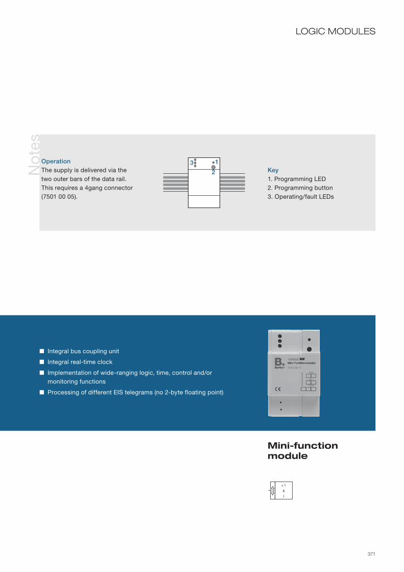
371
No
tes
Mini-function module
LOGIC MODULES
Integral bus coupling unit
Integral real-time clock
Implementation of wide-ranging logic, time, control and/or monitoring functions
Processing of different EIS telegrams (no 2-byte floating point)
Key1. Programming LED2. Programming button3. Operating/fault LEDs
OperationThe supply is delivered via the two outer bars of the data rail. This requires a 4gang connector (7501 00 05).
≥ 1&t
1
2
3

372

373
Displays 374–375Indication and operating panels 376–381
VISUAL REPRESENTATIONS
In residential, public and commercial buildings, the operating states of various sub-systems often need to be recorded and signalled. This requirement covers both the
interior and exterior areas of the buildings concerned. The KNX/EIB installation bus can be used in a multifunctional role to perform
this task. All display, signalling, operator control and monitoring elements can receive information over a bus cable and send commands and
messages to all other devices on the bus. This leads to clearly-structured systems, and reduces costs.
Dim
. dra
win
gs
Glo
ssar
yTr
aini
ng
Ser
vice
Oth
erco
mp
one
nts
Vis
ual
rep
re-
sent
atio
ns
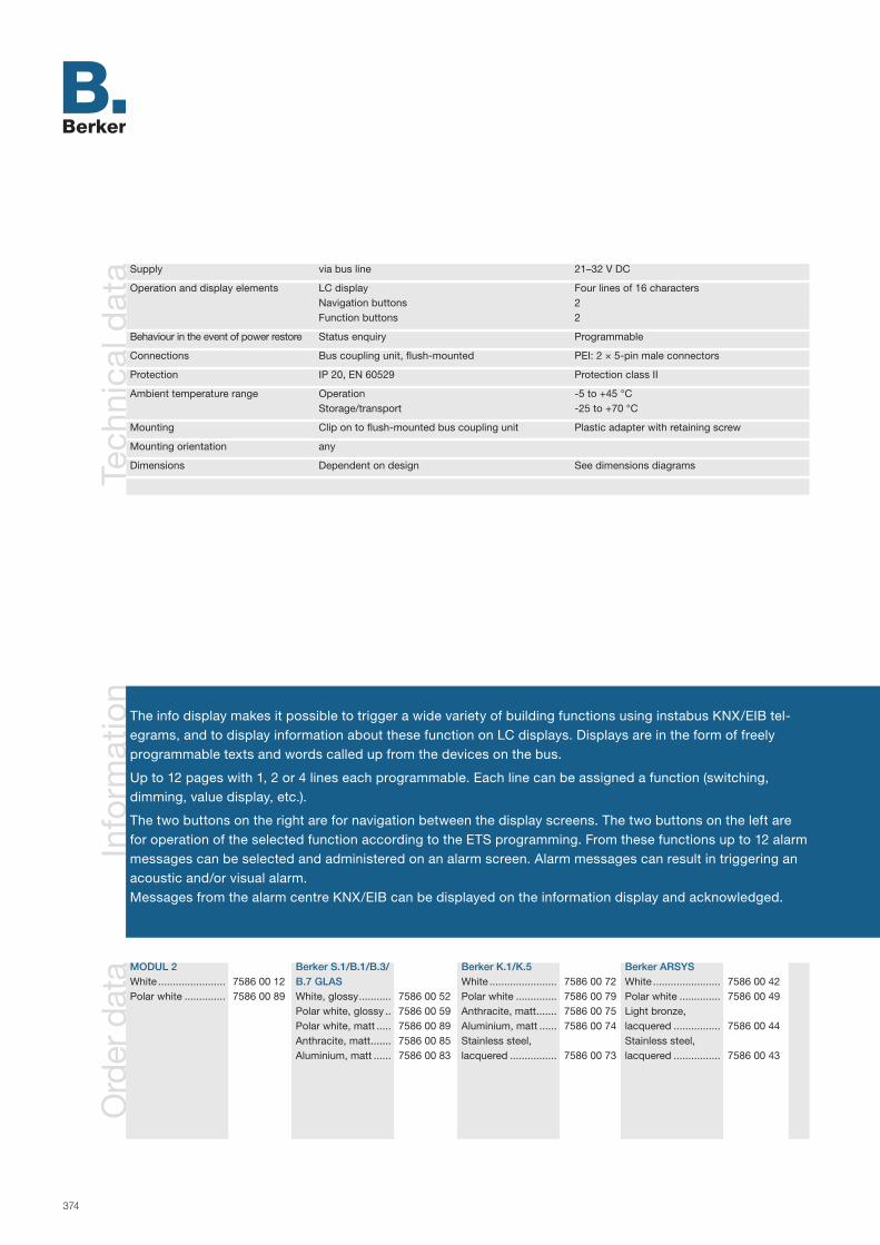
374
Info
rmat
ion
The info display makes it possible to trigger a wide variety of building functions using instabus KNX/EIB tel-egrams, and to display information about these function on LC displays. Displays are in the form of freely program mable texts and words called up from the devices on the bus.
Up to 12 pages with 1, 2 or 4 lines each programmable. Each line can be assigned a function (switching, dimming, value display, etc.).
The two buttons on the right are for navigation between the display screens. The two buttons on the left are for operation of the selected function according to the ETS programming. From these functions up to 12 alarm messages can be selected and administered on an alarm screen. Alarm messages can result in triggering an acoustic and/or visual alarm.Messages from the alarm centre KNX/EIB can be displayed on the information display and acknowledged.
Tech
nica
l dat
a Supply via bus line 21–32 V DC
Operation and display elements LC display Four lines of 16 characters Navigation buttons 2 Function buttons 2
Behaviour in the event of power restore Status enquiry Programmable
Connections Bus coupling unit, flush-mounted PEI: 2 × 5-pin male connectors
Protection IP 20, EN 60529 Protection class II
Ambient temperature range Operation -5 to +45 °C Storage/transport -25 to +70 °C
Mounting Clip on to flush-mounted bus coupling unit Plastic adapter with retaining screw
Mounting orientation any
Dimensions Dependent on design See dimensions diagrams
Ord
er d
ata MODUL 2
White .......................Polar white ..............
7586 00 127586 00 89
Berker S.1/B.1/B.3/B.7 GLASWhite, glossy ...........Polar white, glossy ..Polar white, matt .....Anthracite, matt .......Aluminium, matt ......
7586 00 527586 00 597586 00 897586 00 857586 00 83
Berker K.1/K.5White .......................Polar white ..............Anthracite, matt .......Aluminium, matt ......Stainless steel, lacquered ................
7586 00 727586 00 797586 00 757586 00 74
7586 00 73
Berker ARSYSWhite .......................Polar white ..............Light bronze, lacquered ................Stainless steel, lacquered ................
7586 00 427586 00 49
7586 00 44
7586 00 43

375
Display and operation of building functions
Illuminated LC display
1, 2 or 4-line display (4, 8, 16 characters per line)
Acoustic and/or visual alarms
Display of messages and operation of bus devices
Protection against incorrect use
Values can be presented
Directly programmable using ETS (no special software required)
Info display
VISUAL REPRESENTATIONSA
pp
licat
ions
Display 500D01 Device parameters configurable Selectable line functions: - Dimming the lighting - Retrieve light scene (light scene extension set) - Switching the lighting - Drive shutters - Forced guidance - Display date and/or time of master clock - Send and receive values (up to 4 bytes) - Display text - Display ASCII text Page functions selectable: - No function - Display - Display alarm centre Protection against incorrect use configurable Line functions configurable Alarm functions configurable Lighting can be activated by object Object value sent on removal of the device from the bus coupling configurable
Objects 50 (dependent on the parameterisation)
Group addresses/assignments maximum 78/maximum 127
ETS search path: Berker >> Displays >> LCD displays >>
No
tes
Key1. Protection against removal (under the design cover)2. Info Display3. Two navigation buttons4. Two function buttons5. Design cover
INFO8
1
2
3
5
4

376
Info
rmat
ion
Ord
er d
ata
The Minitableau MT 701 Plus is used to display and modify building functions from a central point. The dis-play medium is an LCD graphical display. The physical external interface is controlled via a membrane keypad using the common Interworking Standards. Basic functions such as switching, dimming and shutter control operation can be handled, as well as complex functions such as value transmission, time, date, etc. The functions of the four input keys can be programmed freely.
The projecting tool to program the Minitableau is a plug-in, which is implemented in the ETS. It has a direct access to the project group addresses. A preview window helps to check the programmed pages.
An internal real-time clock is provided for the time functions. The switching times can be altered without use of a PC. The date and time can be received by system time transmitters and transmitted by the internal value transmitter. It is possible to control and store up to 24 scenes with up to 32 outputs (1-bit, 1-byte). Light scenes can be changed and labelled by the user.
Extension mode operation is possible by way of suitable sensors (value transmitters).
Device colourLight grey ................ 7574 00 09
Tech
nica
l dat
a Supply Bus 21–32 V DC External voltage 230 V AC ±10 %, 50 to 60 Hz Power consumption approx. 3 VA lighting off, approx. 6 VA lighting on
Operation and display elements 4 programmable keys 2 cursor keys Backlighting button Display LCD with 240 x 180 pixels
Connections Bus Terminal Supply voltage Screw-type terminals up to 2.5 mm2
Response to power Bus voltage Last display values are retainedfailure Mains voltage Device does not function Bus and mains power Device does not function
Response to power Bus or mains power Status polling of bus devices and updatingrestore of display values Bus and mains power Status polling of bus devices and updating of display values (if function selected in plug-in software)
Protection Depending on size and properties of mounting area up to IP 54, EN 60529
Ambient temperature range Operation -5 to +45 °C Storage/transportation -25 to +70 °C
Mounting Bolted into flush-mounted housing
Mounting orientation any
Dimensions (WxHxD) Visible dimensions 213 x 125 x 75 mm without decor frame 216 x 145 mm with decor frame (accessory) Cavity installation dimensions (hole dimensions) 212 x 124 x 75 mm for flush-mounted housing
AccessoriesMasking frame- Polar white ............- Deep black ............- Light bronze,
lacquered .............- Stainless steel,
lacquered .............
Flush-mounted housing ...................
7594 00 097594 00 05 7594 00 04 7594 00 03 7590 00 21

377
ETS search path: Berker >> Displays >> LCD displays >>
Graphical display with 240 x 128 pixels
Backlighting
Contrast adjustable
Background bitmaps insertable
Up to 50 dialogue pages each with
sixteen functions in eight lines
programmable
Four membrane push-buttons freely
programmable for interactive user
control
Two cursor push-buttons
Illumination push-button
Minitableau MT 701 Plus
VISUAL REPRESENTATIONS
System time buffered (approx. 3 days)
Switching times programmable with
use of PC
Password functions
Alarm functions
Limiting value functions
Sixteen-channel timer function
(week program)
Light scene function with extension
mode
Integral programming interface
Programming via KNX/EIB possible
No
tes Alarm functions Definition and processing by alarm list (190 entries)
Representation by pop-up functions and/or acoustic signals
Limiting value functions Definition from up to eight telegrams Processing into switching telegrams Representation as analogue values
Password functions Structure Four segments, hierarchical, segment 4 has highest priority Backup in EEPROM – Backup also in case of power failure and project redesign Password selection possible without software Password changing possible without software
Key1. “Illumination” push-button2. Cursor “Up” 3. Cursor “Down”4. Context-sensitive menu keys5. Display6. PC port and bus connection
on rear
1
5 2
3
4
6

378
Info
rmat
ion The Berker Master Control is used to depict and operate building functions at a central point. This is done
using a colour touch screen (TFT display), whose user interface can be custom configured. The functions of the display elements can be set freely. Basic functions such as switching, dimming, shutter and complex functions such as value transmitter, time, date, etc. can be edited. In addition, an Ethernet interface is avail-able, via which up to 5 e-mail mailboxes can be synchronised, and text contents of e-mail messages can be called up, all under password protection. It is also possible to transmit predefined fault messages via e-mail. What is more, RSS newsfeeds can be displayed. The display and operation functions of the master control can be visualised remotely and at the same time controlled using easy-to-install PC client software (remote communication). Furthermore, the Ethernet interface enables user-oriented configuration and commissioning of the master control.
Configuration is carried out via a software plug-in integrated into the ETS which allows the transfer of group addresses. A preview screen allows direct control of the display page created.
Tech
nica
l dat
a Supply via bus line 21 – 32 V DC Auxiliary voltage 230 V ~ AC, 50/60 Hz Power consumption approx. 13.8 W Power consumption in standby approx. 5 W
Operation and display elements Touch screen, colour TFT display, 320 x 240/240 x 320 pixels, 4096 colours Programming button with programming LED, red Reset button with reset LED, red
Graphics memory for icons and background images approx. 4 MB
Behaviour in the event of power failure Bus voltage Display values are depicted with dashes, Display elements are not depicted no operating via the instabus KNX/EIB Mains voltage no function of the device Bus and mains voltage no function of the deviceBehaviour when power returns Bus or mains voltage Status query of the bus devices and update of the display values Bus and mains voltage Status query of the bus devices and update of the display values (if this function has been selected in the plug-in software)
Connections KNX/EIB Connection terminal Programming interface USB socket, type B Ethernet, 10 Mbit/s RJ45 jack 8/4pole Screw terminals Mains voltage 0.5 – 2.5 mm² single stranded 0.5 – 2.5 mm² finely stranded without cond. sleeve 0.5 – 1.5 mm² finely stranded with cond. sleeve
Protection class IP 20, EN 60529
Ambient temperature range Operation or storage/transport -5 to +45 °C / -25 to +75 °C
Mounting in flush-mounted housing
Mounting orientation horizontal or vertical preferably horizontal
Dimensions (WxHxD) Visible dimensions 220 x 140 x 48 mm without frame 231 x 159 x 48 mm with frame Panel hole dimensions, hollow wall (hole dimensions) for flush-mounted housing 212 x 124 x 75 mm
Ord
er d
ata Device colour
Polar white ..............Anthracite ................
7574 00 127574 00 13
AccessoriesFrame- Glass, polar white ...- Stainless steel .......Flush-mounted housing ...................
7594 01 017594 01 03
7590 00 21
continued on next double page

379
Colour touch screen (TFT display with 320 x 240 pixels) Bitmap/JPG graphics can be inserted Up to 50 dialogue pages, each with up to 16 display elements Total of 400 display elements possible Switching times adjustable without PC System time with C backup (approx. 3 days) Four password levels for controlling access Alarm functions Limit value functions
Ap
plic
atio
ns
ETS search path: Berker >> Display >> Panel >>
continued on next double page
Berker Master Control
VISUAL REPRESENTATIONS
Master Control 590101 Duration/type of activation of the display illumination adjustable, activation via object possible Display format, sending and updating behaviour of date and time adjustable Display depiction for horizontal and vertical mounting Mode of depiction adjustable by means of numerous parameters Display of 50 dialogue pages possible with free design and integration of graphics Password protection possible for each display page Adjustable display elements (e.g. buttons) with configuration preview and operation via photo-realistic
room depiction possible, e.g. as floor plan Character sets for Western and Eastern Europe, Greek and Cyrillic Parts of a project can be saved for re-use as function blocks Functions switching, dimming, shutter, value display (if desired with limit value monitoring), light scene,
date, time, text display, access control, positive operation and operating mode change-over, heating for display elements adjustable Possible to show a 4-button line at the lower edge of the display with the selectable functions swit-
ching, dimming, shutter, value, light scene, positive operation and calling other display dialogue pages Possible to show a status line with a display of events, fault messages, values, date, time or texts Service page for system settings Four password levels for assigning various access rights Adjustable integrated week time switch with sixteen timer channels on two timer pages Up to 50 fault messages can be set Possible to display the last 20 fault messages with opening of a message window and acoustic signal Acknowledgement of fault messages via display or object 80 logic operations (AND, OR, exclusive OR) can be programmed for convenient linking/processing of
statuses and events 12 multiplexers with up to three channels can be programmed Up to 40 time elements with filter, time and blocking parameters programmable for switching functions Password-protected synchronisation of up to 5 e-mail mailboxes and writing of the text contents of
e-mail messages.

380
Info
rmat
ion
An internal real-time clock is available for processing the time functions. The switching times can be changed without a PC intervention. Date and time can be received by system timers and also transmitted by the inter-nal value transmitter.
Control (possible even via the integrated time switch) and saving of up to 24 light scenes with up to 32 outputs (1 bit, 1 byte) are possible, light scenes and descriptive texts can be changed. Extension unit operation is pos-sible using suitable sensors (value transmitters).
A presence simulation and a data logger function can be implemented as additional functions. The presence simulation can be used to record any desired simulations over certain time periods, and to play them back at any time. The data logger provides the capability of recording the data that are received from the KNX/EIB in various formats and to depict them on the device, e.g. as a diagram, or to forward them via e-mail.
Ap
plic
atio
ns
Master Control 590101 (continued) Display of up to 8 RSS news feeds (RSS 2.0) in colour on the touch screen Remote communication for display and operation of the master control via a PC Presence simulation for recording or playback of any desired simulations adjustable via specific time sequences Data logger for recording and depiction of KNX/EIB data, and forwarding via e-mail possible Integrated alarm system with up to two different alarm areas (internal/external) for monitoring of windows and doors for burglary and sabotage
Objects max. 2,000, generated dynamically
Group addresses /assignments maximum 3,000/maximum 3,000

381
Integrated alarm system with two alarm areas Week time switch with 16 channels, each with 8 switching times Light scene operation with extension unit operation Programming possible via KNX/EIB or USB Integrated piezo buzzer
VISUAL REPRESENTATIONS(Continued)
Info
rmat
ion Legend
1. USB connection on the rear of the device (blade terminal)
2. Connection Ethernet 8pole3. USB connection to the front of the
device (USB type B)4. Mains voltage connection 5. KNX/EIB bus connection6. Programming LED 7. Programming button 8. Connection for future expansions,
e.g. membrane keyboard 9. Reset button 10. Reset LED
Legend11. Status line12. User interface with freely selecta-
ble background graphics and display elements
13. Scroll bar14. Four button displays (optional)15. Display element (up to 16 freely
positionable per dialogue page)
Connections (rear of device)
Touch screen operating elements
5
6 7
4
2
3
1
8 9 10
11
15 1213
14
Berker Master Control

382

383
IP-Control 384–387Gateways 388–393 Alarm central unit 394–397Tele-Control 398–399
OTHER COMPONENTS
The instabus KNX/EIB connects and links all subsystems within a building.
In accordance with modern requirements, it should also be possible to communicate with the system or activate facilities from outside the building via contemporary
means of communication such as the Internet and e-mail (IP-Control).
Gateways create the connection from standardised systems to the instabus KNX/EIB so that the PDA rises up to the cable-less operating centre of a room (Bluetooth
gateway) or the light is switched on via the television remote control (IR gateway).
The alarm centre uses the instabus KNX/EIB to control all components; the connection to the building system technology creates synergies through the use of movement
detectors to control the lighting and monitor the interior.
It is not just a question of convenience but also of security when important information such as burglary reports or fire alarms can
be reported to nearly every place by telephone (Tele-Control).
Dim
. dra
win
gs
Glo
ssar
yTr
aini
ng
Ser
vice
Oth
erco
mp
one
nts

384
Info
rmat
ion
Ord
er d
ata Device colour
Light grey ................ 7571 00 04
Tech
nica
l dat
a
The IP Control is designed as a rail mounted device. Berker IP Control is a central control, signalling and monitoring unit that captures all of the information from a KNX/EIB installation. The information is transmitted via an IP interface. All of the KNX/EIB functions are processed and visualised with the aid of the pre-installed software.
IP Control functions like a server and allows additional functions such as:
- Coupling of multiple KNX/EIB systems with their own IP Control via the LAN interface
- Independent access to the building functions from each (mobile) PC for nearly unlimited mobility
- Simultaneous access by up to 50 visualisation clients (including decentralised ones) for users with individual user rights
Supply via bus line 21–32 V DC Auxiliary voltage 12 – 30 V DC Power consumption max. 5W
Operation and display elements Power LED (operational stand-by) green/orange BMX LED (data traffic) red/green/orange KNX/EIB LED (KNX/EIB-data exchange) red/green /orange LAN LED (LAN connection) green /orange Programming button Programming LED red
Connections KNX/EIB Connection terminal Power supply Screw terminals Ethernet interface RJ45 jack
Memory RAM 64 MB ROM 64 MB
Protection class IP 20, EN 60 529
Ambient temperature range Operation 0 to +35 °C Storage/transport -20 to +70 °C
Mounting on top hat rail 35 mm, EN 50022
Dimensions (W x H x D) 144 x 90 x 64 mm 8 modules
continued on next double page

385
IP Control
OTHER COMPONENTS
Convenient visualisation via PC
Basic project with preconfigured function blocks
Week and year timers
Logic gates
Light scene control
Threshold switches with hysteresis
Space-saving RMD installation
Info
rmat
ion the JAVA Runtime Engine version 1.5
or higher must be installed on the application PC.
Legend1. Power supply 10–30 V DC2. Signal LED (operation)3. RJ45 jack for Ethernet LAN4. Programming button KNX/EIB5. Programming LED KNX/EIB6. Bus connection terminal KNX/EIB
NOTE
The non-reduced output of a KNX/EIB voltage supply can be used as the voltage supply.
IP Control requires no ETS appli-cation. It is not necessary to pro-gram the bus coupling unit.
Network technology skills are required for commissioning and configuration.
When using a direct connection to a PC, use a crossover network cable.For the complete range of functions,
continued on next double page
EIB
1
2 3
6
4 5
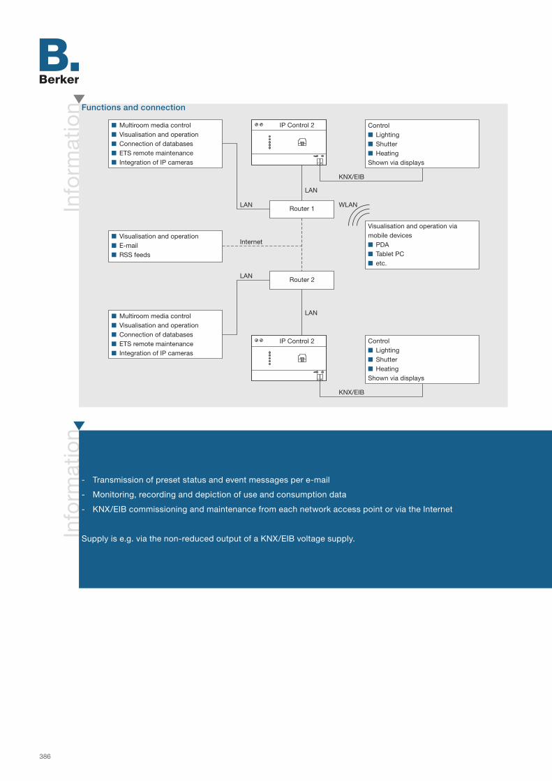
386
Info
rmat
ion
Info
rmat
ion
- Transmission of preset status and event messages per e-mail
- Monitoring, recording and depiction of use and consumption data
- KNX/EIB commissioning and maintenance from each network access point or via the Internet
Supply is e.g. via the non-reduced output of a KNX/EIB voltage supply.
Functions and connection
Multiroom media control Visualisation and operation Connection of databases ETS remote maintenance Integration of IP cameras
Control Lighting Shutter HeatingShown via displays
Control Lighting Shutter HeatingShown via displays
Visualisation and operation viamobile devices PDA Tablet PC etc.
Multiroom media control Visualisation and operation Connection of databases ETS remote maintenance Integration of IP cameras
Visualisation and operation E-mail RSS feeds
Router 1
Router 2
IP Control 2
IP Control 2
Internet
LAN WLAN
LAN
KNX/EIB
KNX/EIB
LAN
LAN

387
OTHER COMPONENTS(Continued)
IP Control
Info
rmat
ionUser interface
The IP Control can be reached via its IP address using a Web browser. The following functional areas can be selected from the start page:
VisualisationUser interface that is used to transmit commands to and to display status information from the KNX/EIB system via IP Control. The user interface can be created or edited in a project using the editors provided. The editors are provided by IP Control via the network. Berker provides a preset basic project with prepared graphics and preconfigured func-tion blocks; this makes it easier to commission and design new projects.
Visualisation EditorEditor for designing the user interface. Visualisation elements are integrated and can be selected via the menu bar. In addition, you can create elements yourself using the supplied software. The visualisation elements can be imported and selected in the editor, texts can be added and parameterised. In the background you can insert your own graphics (e.g. floor plans) or photographs for individual designs.
Job EditorCreation of additional jobs. Jobs are tasks/functions that IP Control can execute independently: Week and year timers Timer, switch-on and switch-off delay Light scenes with up to 28 KNX devices Limit value and hysteresis switches Event-controlled sending of e-mails Logic gates (operations) AND, OR, XOR and negation of the corresponding logic Comparison of values of the group addresses with results-dependent transmission of values Outputting of RSS feeds as scrolling text on EIS 14-capable visualisation devices Setting-up of a multiroom media control with operation via KNX/EIB components
System ConfiguratorInterface for configuration of the device. IP addresses, e-mail providers, the time zone, passwords, physical address-es, etc. are set here. Your own graphics and operating elements are loaded into the device. Backup files for projects and settings can be created and links to a database can be set up.

388
Info
rmat
ion
Ord
er d
ata
Tech
nica
l dat
a
Device colourLight grey ................ 7571 00 03
The DALI Gateway is designed as a rail mounted device and serves as the interface between a KNX/EIB installation and a DALI lighting system. It makes it possible to switch and dim up to 64 lights with a DALI oper-ating device (e. g. electronic ballast) that can be assigned to up to 32 different light groups. Activation of the DALI Gateway makes possible room-specific light control in the higher-level KNX/EIB building management. Additionally, the light groups can be integrated into up to 16 scenes, meaning that it is possible to call up pre-programmed lighting moods, for example.
The operating devices (4 push-buttons) can be used to switch the DALI light groups on and off or dim them in parallel with KNX/EIB, even without bus voltage or in an unprogrammed state. This enables quick function testing of the connected loads.The device is configured and commissioned via a plug-in embedded in the ETS 3. The DALI Gateway is supplied with power entirely from the separate mains connection.
The mains voltage must be switched on in order to activate the DALI interface.
Supply via bus line 21– 32 V DC
Auxiliary voltage 110 to 240 V AC +10 %/-15 % 50/60 Hz Power consumption maximum 6 W
DALI Voltage typ. 16 V DC (with overvoltage protection) Current typ. 128 mA, maximum 200 mA briefly designed for max. 64 DALI devices with 2 mA each with short-circuit and overload protection Transmission rate 1200 bit/s
Cable lengths between Ø 1.5 mm² or Ø 1.0 mm² maximum 300 m or maximum 238 mGateway and operating device Ø 0.75 mm² or Ø 0.5 mm² maximum 174 m or maximum 116 m Resistivity maximum 4 ohm (one-way length) maximum 8 ohm (two-way cable) Cable type Specified by FELV; preferably two free cores of an NYM installation cable
Behaviour in the event of power failure Bus voltage failure software-dependent Mains voltage failure According to its parameterisation, the device reports failure of the supply voltage on the bus and then switches off
Behaviour in the event of power Bus voltage software-dependentreturn Mains voltage brief initialisation, then readiness for operation
Operation and display elements Button field 4gang Local operation 3 local operation status LEDs, 1 programming LED Red Programming button
Connections KNX/EIB Connecting terminal Inputs single-core 0.2–4 mm² or 2 x 0.2–2.5 mm² 0.75–4 mm² finely stranded without conductor 0.5 –2.5 mm² finely stranded with conductor
Protection IP 20, EN 60529
Ambient temperature range Operation and storage/transport -5 to +45 °C and-25 to +70 °C
Installation/mounting orientation on top hat rail 35 mm, EN 50022 as desired, preferably output terminals up
Dimensions (W x H x D) 72 x 90 x 58 mm 4 modules

389
Ap
plic
atio
nsN
ote
s
DALI gateway
OTHER COMPONENTS
Interface to DALI lighting systems
Control of 64 lights in up to 32 lighting groups
Provision of the DALI system voltage
Four buttons for manual operation with LED display
Two-character, seven-segment display for DALI groups and status information
DALI Gateway C00C01 Control of max. 64 DALI devices in a max. of 32 groups Parameters for activation and function of manual operation adjustable Feedback of DALI error state or short-circuit Switching feedback: active or passive (object can be read out) feedback function Message in the event of failure of the supply voltage Soft switch-on or soft switch-off function Central switching function DALI commissioning with ETS plug-in Brightness limit value adjustable Dimming behaviours adjustable Lock function or alternatively forced guidance function can be set for each group; in the lock function
flashing of light groups is possible Adjustable time functions (on delay, off delay, stair light function –also with prewarning function) The groups can be included in up to 16 light scenes Responses in the event of bus voltage failure and return and after an ETS programming process can
be set for each group
Objects 216
Group addresses/assignments maximum 254/maximum 255
ETS search path: Berker >> Lighting >> Dimmer
Terminalsda = DALI system voltage
Key1. DALI device (e. g. electronic ballast, up to 64 devices2. Display3. Programming button4. Bus connection 5. Programming LED6. Buttons 1/5 and 0 /6 each with associated LED7. Manual button with associated LED8. OFF button
4
12
4356
7 8

390
Info
rmat
ion
Tech
nica
l dat
a
The Bluetooth gateway is clipped onto a flush-mounted bus coupling unit, and sends and receives Bluetooth signals wirelessly. Bluetooth signals are converted into KNX/EIB telegrams and vice versa at the gateway. This allows lights, shutters and heaters to be operated with the correct Bluetooth terminal devices and their current status to be visualised. The physical external interface in the terminal device is designed with specific systems in mind and is tailored to the specific application.
Up to eight terminal devices can be administered. The terminal devices are registered, and the settings and configuration performed using the displays and the four device buttons. No re-programming is necessary. Frequency hopping during transmission from gateway to terminal device keeps the connection immune from interference.
Supply via bus line 21–32 V DC
Controls and display elements Buttons 4 Graphic display four lines with 16 characters
Bluetooth 2.4 GHz ISM-Band 79 channels Frequency hopping 1600/sec Transmitting power 10 mW Transmission/reception range approx. 10 m in class 3
Protection IP 20, EN 60529
Ambient temperature range Operation -5 to +45 °C Storage/transport -25 to +75 °C
Mounting Clip on to flush-mounted bus coupling unit plus
Mounting orientation any
Dimensions (W x H x D) depends on design see dimension drawings
Ord
er d
ata MODUL 2
White .......................Polar white ..............
7566 01 127566 01 19
Berker S.1/B.1/B.3/B.7 GLASWhite, glossy ...........Polar white, glossy ..Polar white, matt .....Anthracite, matt .......Aluminium, matt ......
7566 01 527566 01 597566 01 897566 01 857566 01 83
Berker K.1/K.5White .......................Polar white ..............Anthracite, matt .......Aluminium, matt ......Stainless steel, lacquered ................
7566 01 727566 01 797566 01 757566 01 74
7566 01 73
Berker ARSYSWhite .......................Polar white ..............Light bronze, lacquered ................Stainless steel, lacquered ................
7566 01 427566 01 49
7566 01 44
7566 01 43
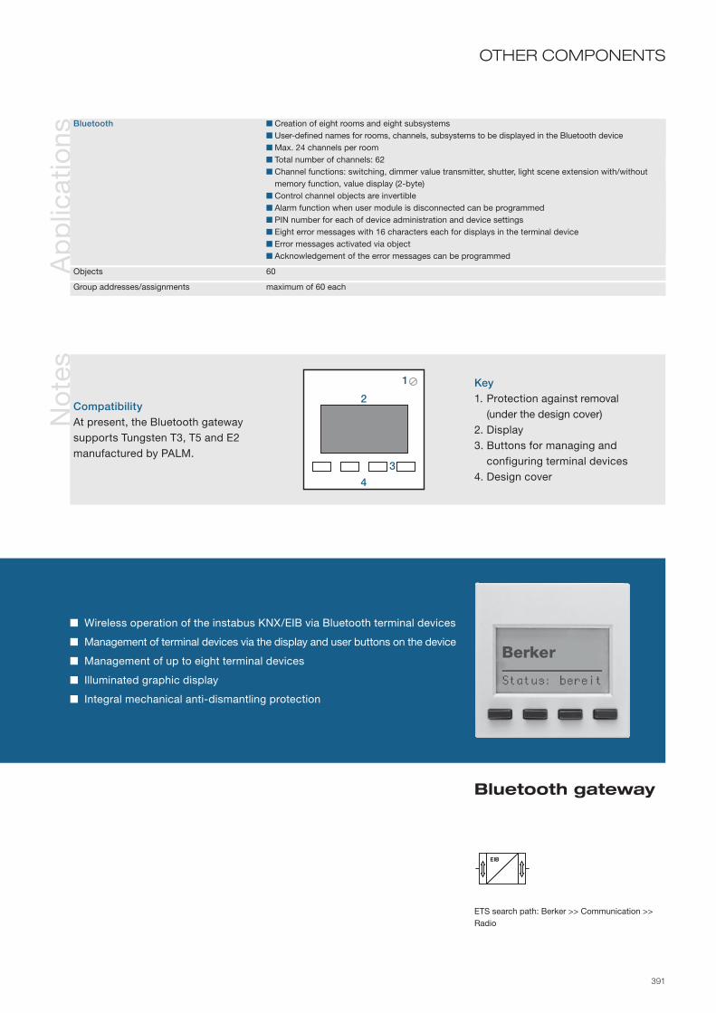
391
Wireless operation of the instabus KNX/EIB via Bluetooth terminal devices
Management of terminal devices via the display and user buttons on the device
Management of up to eight terminal devices
Illuminated graphic display
Integral mechanical anti-dismantling protection
Bluetooth gateway
Ap
plic
atio
ns
Bluetooth Creation of eight rooms and eight subsystems User-defined names for rooms, channels, subsystems to be displayed in the Bluetooth device Max. 24 channels per room Total number of channels: 62 Channel functions: switching, dimmer value transmitter, shutter, light scene extension with/without
memory function, value display (2-byte) Control channel objects are invertible Alarm function when user module is disconnected can be programmed PIN number for each of device administration and device settings Eight error messages with 16 characters each for displays in the terminal device Error messages activated via object Acknowledgement of the error messages can be programmed
Objects 60
Group addresses/assignments maximum of 60 each
ETS search path: Berker >> Communication >> Radio
OTHER COMPONENTSN
ote
s
Key1. Protection against removal (under the design cover)2. Display3. Buttons for managing and configuring terminal devices4. Design cover
CompatibilityAt present, the Bluetooth gateway supports Tungsten T3, T5 and E2 manufactured by PALM.
EIBEIB
1
2
3
4

392
Info
rmat
ion
Tech
nica
l dat
a
The IR gateway is clipped onto a flush-mounted bus coupling unit V2, and sends and receives IR signals. Incoming KNX/EIB telegrams are converted into IR signals, and can then control IR-controllable devices such as televisions and audio systems or integrate them into scenes. In the same way, IR signals are converted into KNX/EIB telegrams so that KNX/EIB devices can be operated with IR remote controls.
By using several IR gateways, the instabus-KNX/EIB can be used as a transmission link to allow for simplified, IR control from one room to another. For this purpose, the IR signal is converted into an KNX/EIB telegram, is forwarded and then re-converted into an IR signal elsewhere.
In teach-in mode, the IR gateway can learn nearly all standard IR remote controls (e. g. with RC5 code) and convert their signals into KNX/EIB telegrams. A reset function to delete all IR signals is integrated into the IR gateway.
Supply via bus line 21–32 V DC
Controls and display elements Rotary potentiometer Reset Slide switch Operating statuses: - operation (left position) - standby (central position) - learning (right position) LED, three colours Operating status displayed beneath the lens
Connections Bus coupling unit V2, flush-mounted PEI: 2 × 5-pin male connectors
IR range Transmission and reception angle 30° Transmission/reception range approx. 7 m
IR signals Scanning and sending 20–70 kHz and 455 kHz Reception 34–42 kHz and 455 kHz
Protection IP 20, EN 60529
Ambient temperature range Operation -5 to +45 °C Storage/transport -25 to +75 °C
Mounting Clip on to bus coupling unit V2, flush-mounted
Mounting orientation Ensure it is aligned with transmitters and receivers
Dimensions (W x H x D) depends on design see dimension drawings
Ord
er d
ata MODUL 2
White .......................Polar white ..............
7566 03 127566 03 19
Berker S.1/B.1/B.3/B.7 GLASWhite, glossy ...........Polar white, glossy ..Polar white, matt .....Anthracite, matt .......Aluminium, matt ......
7566 03 527566 03 597566 03 897566 03 857566 03 83
Berker K.1/K.5White .......................Polar white ..............Anthracite, matt .......Aluminium, matt ......Stainless steel, lacquered ................
7566 03 727566 03 797566 03 757566 03 74
7566 03 73
Berker ARSYSWhite .......................Polar white ..............Light bronze, lacquered ................Stainless steel, lacquered ................
7566 03 427566 03 49
7566 03 44
7566 03 43
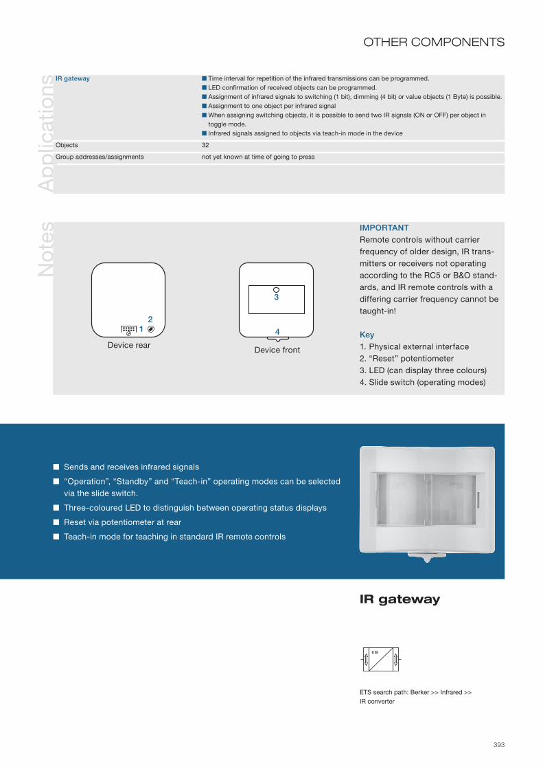
393
IR gateway
ETS search path: Berker >> Infrared >> IR converter
OTHER COMPONENTS
Sends and receives infrared signals
“Operation”, “Standby” and “Teach-in” operating modes can be selected via the slide switch.
Three-coloured LED to distinguish between operating status displays
Reset via potentiometer at rear
Teach-in mode for teaching in standard IR remote controls
Ap
plic
atio
nsIR gateway Time interval for repetition of the infrared transmissions can be programmed. LED confirmation of received objects can be programmed. Assignment of infrared signals to switching (1 bit), dimming (4 bit) or value objects (1 Byte) is possible. Assignment to one object per infrared signal When assigning switching objects, it is possible to send two IR signals (ON or OFF) per object in
toggle mode. Infrared signals assigned to objects via teach-in mode in the device
Objects 32
Group addresses/assignments not yet known at time of going to press
No
tes IMPORTANT
Remote controls without carrier frequency of older design, IR trans-mitters or receivers not operating according to the RC5 or B&O stand-ards, and IR remote controls with a differing carrier frequency cannot be taught-in!
Key1. Physical external interface2. “Reset” potentiometer3. LED (can display three colours)4. Slide switch (operating modes)
EIB
Device front
3
4
Device rear
12

394
Info
rmat
ion
Ord
er d
ata
Tech
nica
l dat
a
The alarm central unit KNX/EIB is designed for surface-mounting. It links all system components of the alarm system and coordinates their functions. The alarm centre monitors the detectors and activation equipment and controls the alarm sensors and displays. So as to offer systems appropriate both to the structures of residential buildings and also small trade business premises, up to four security zones can be configured as the application requires.
In addition, two zones are available for monitoring fire detectors and burglary detectors. Programming is performed using an easy-to-use software plug-in, which displays the structure of the alarm system in diagrammatic overview. Events such as activations, alarms, errors are recorded in an event log with time and date.
For large buildings, several alarm centres can be set up, which monitor one another.
Supply via bus line 21 to 32 V DC Power consumption typically 240 mW Auxiliary power supply 230 V AC ±10 %, 50 to 60 Hz Power consumption max. 24 W
Inputs all following inputs in common: - Signal duration minimum 100 ms - Signal current typically 500 µA (when closed)
Wired detectors 1 - Signal voltage approx. 4.7 V DC (when open = “1” signal) - Detector resistance max. 1.7 kOhm (when closed) - Length of the input cable max. 200 m (minimum. 0.8 mm cable diameter)
Sabotage 1 - Signal voltage approx. 4.7 V DC (when open = “1” signal) - Length of the input cable max. 600 m (minimum. 0.8 mm cable diameter)
Transfer device (ÜG-R) 1 - Signal voltage external max. 5 V DC SELV - Signal recognition “1” signal: ≥ 2 V DC / “0” signal: 0–0.8 V DC - Length of the input cable max. 200 m (minimum 0.6 mm cable diameter)
Outputs Alarm sensors 3: External/internal sirens and flash - Switch type Power MOS-FET for each output - Rated voltage 12 V DC SELV each output (±1.5 V back-up power operation) - Rated current max. 1.6 A (all 3 outputs together) - Length of output cable max. 200 m (minimum. 0.6 mm cable diameter)
Transfer device - Supply 2: 1 x 12 V DC and 1 x GND ÜG (–) - Control outputs 5: 1 each × ÜG-S/U, ÜG-E, ÜG-F, ÜG-Ü and ÜG-S - Rated voltage 12 V DC SELV each output (±1.5 V back-up power operation) - Switch type Transistor for each control output - Rated current (supply and control outputs) max. 100 mA - Length of output cable max. 200 m (minimum. 0.6 mm cable diameter)
Relay output 1 × normally open (NO) and 1 × normally closed (NC) - Switch type Potential-free relay contacts
Device colourAlarm central unitPolar white/black.....
Back-up batteryBlack .......................
7573 00 10
9200 01
Continued on next double page

395
Four individually configurable security zones with up to 160 detectors
Decentralised display and operation e. g. using the information display
Individual identification and monitoring of all detectors via the KNX/EIB
Direct connection of the alarm sensors (siren, flash, transfer device) to the alarm centre and/or control of alarm sensor via the KNX/EIB
Back-up battery for continuous operation up to 12 hours
Potential-free output for e.g. additional alarm sensors
Sabotage protection by cover contact
Self-protection by means of local detector input (wired detectors)
Alarm central unit
Ap
plic
atio
ns
Alarm centre C00401 ETS plug-in for easy programming of the alarm centre 15 practical configurations for structuring the alarm system Permanent monitoring of the zones for fire and break-in, irrespective of whether the system is activated Max. 160 dynamically addressed detector inputs with freely selectable designations Individual identification and monitoring of all detectors Various types of detectors can be programmed for different applications Freely selectable designations for all zones Four switching devices per activation zone with individual identification for anti-sabotage protection Deactivation of switching devices in the event of sabotage Activation delays programmable by zone Objects for activating/deactivating acknowledgement can be set by zone Alarm delays programmable by zone Advance alarm programmable by zone via object Alarm output configurable for all zones and for the additional fire and break-in zones Alarm duration for flash light, external and internal sirens programmable Display and transfer of error messages 4 groups of displays (e.g. information displays) with individually programmable display configurations Mutual functional monitoring of multiple alarm centres by input/output object Cyclical functional monitoring of the mutual communication signals Dynamic event log for recording the last 400 events (e.g. alarms, errors) System log can be sent from the ETS to a printer or to a file Facility for synchronisation of the integral system clock via KNX/EIB object (e.g. by DCF-77 receiver) Detector test mode for function testing of all detectors in the alarm system
Objects 231
Group addresses/assignments maximum of 254 each
ETS search path: Berker >> Alarm technology >> Alarm centre >>
OTHER COMPONENTS
Continued on next double page
EIB

396
Info
rmat
ion
Tech
nica
l dat
a Outputs (continued) - Switching voltage 12 V AC/DC - Switching current/minimum load max. 5 A/30 mA - Length of output cable max. 200 m (minimum. 0.6 mm cable diameter)
Additional output 12 V DC 1 × 12 V DC and 2 × GND - Rated voltage 12 V DC SELV (±1.5 V back-up power operation) - Rated current max. 100 mA - Length of output cable Dependent on load relative to cable diameter
Behaviour on power Bus power failure Configurable using plug-in jumper J1 (see item 12)failure/restore Mains power failure Event-dependent, supply from battery Bus and mains power failure Configurable, supply from battery Bus power restoration Configurable Mains power restoration Event-dependent Bus and mains power restoration Configurable
Operation and display elements Plug-in jumper J1 Determines behaviour in the event of bus power failure Programming button Programming LED Red 9 + 1 status LEDs Red/green (status bus power, see item 13)
Connections KNX/EIB Terminals Auxiliary voltage: Screw terminals max. 4 mm² single wire max. 2.5 mm² fine wire without end cap sleeve max. 1.5 mm² fine wire with end cap sleeve Inputs and outputs: Screw terminals max. 1.5 mm² single wire max. 1.0 mm² fine wire without end cap sleeve max. 0.75 mm² fine wire with end cap sleeve
Protection IP 20, EN 60529
Ambient temperature range Operation/storage/transport -5 to +45 °C / -25 to +75 °C
Battery Type Lead-gel battery Rated voltage/capacity 12 V DC/1.2 Ah Charging voltage/current 13.4 V DC/max. 150 mA
Mounting/Mounting orientation Wall-mounted Preferably upright
Dimensions (W×H×D) 210 x 270 x 70 mm
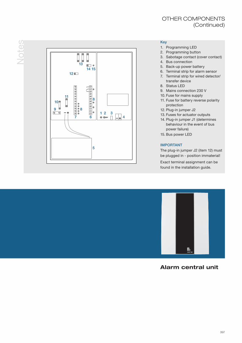
397
OTHER COMPONENTS(Continued)
No
tes Key
1. Programming LED2. Programming button3. Sabotage contact (cover contact)4. Bus connection5. Back-up power battery6. Terminal strip for alarm sensor7. Terminal strip for wired detector/ transfer device8. Status LED9. Mains connection 230 V10. Fuse for mains supply11. Fuse for battery reverse polarity protection12. Plug-in jumper J213. Fuses for actuator outputs14. Plug-in jumper J1 (determines behaviour in the event of bus power failure)15. Bus power LED
IMPORTANTThe plug-in jumper J2 (item 12) must be plugged in - position immaterial!
Exact terminal assignment can be found in the installation guide.
Alarm central unit
+–+– 1 2 3
4
8
9
5
10
11
12
1314
8
15
67

398
Info
rmat
ion
Tech
nica
l dat
a
The Tele-control is designed as a surface-mounted device, and is the linking element between the KNX/EIB and electrical installations, and the telephone network. It is used as a remote switching and fault signalling device. Six 12 V switching outputs and ten KNX/EIB output objects are available for remote switching; activation is via telephone with DTMF signals (tone dialling). Faults and alarm signals can be detected via six conventional signal inputs with potential-free contacts and ten KNX/EIB input objects, and forwarded to up to four freely selectable telephone numbers per input. The fault message can be transmitted as a voice message, fax/SMS, or e-mail (provider required).
Commissioning is performed conveniently via PC using the supplied software or via the integrated rotary switch on the device. The display supports commissioning via clear texts and provides information at all times as to the states of the inputs and outputs.
Power supply is via the wall wart included in the scope of supply.
Supply via bus line 21 – 32 V DC Primary auxiliary voltage (wall wart) 100 – 240 V AC, 50/60 Hz Secondary auxiliary voltage (wall wart) 12 V DC, max. 1.25 A Power consumption max. 10.2 W
Inputs 6 signal inputs potential-free 10 KNX/EIB inputs via object
Outputs 6 switching outputs 12 V DC, 100 mA 10 KNX/EIB outputs via object 1 local alarm output 12 V DC, 100 mA Fault message telephone connection
Telephony Analogue connection CTR 21 Dialling method Pulse dialling or DTMF Telephone numbers for signals 4 per signal input Telephone numbers, KNX/EIB-signal inputs 4 per input
Operation and display elements LC display, 4-line Display: states of the inputs/outputs Rotary switch Device configuration, alarm acknowledgement
Connections KNX/EIB Plug-in spring terminal Power supply Wall wart, 2 m connecting cable Telephone connection cable 3 m, RJ12 TAE plug, N-coded PC serial, RS232
Protection class IP 30, EN 60 529
Ambient temperature range Operation -5 to +45 °C Storage/transport -25 to +70 °C
Mounting Surface-mounted, wall mounting
Dimensions (WxHxD) 205 x 251 x 49 mm
Ord
er d
ata Device colour
Light grey ................ 7573 00 11AccessoriesHeadsetblack ........................ 7590 00 09

399
10 KNX/EIB output objects for remote switching of bus devices
10 KNX/EIB input objects for forwarding of fault/alarm messages
Access protection via 4-digit PIN
Four-line plain text display
Mains failure safe memory for programs
Additional switching output "Alarm" in case of telephone fault
Tele-control
Ap
plic
atio
nsTelecommunications interface Input object type 1-bit, 1-byte, 2-byte and EIS type adjustable for each signal input Function of the switching object can be set as NC or NO Limit value for activation and deactivation of the signal adjustable for each input value object Output object type 1-bit, 1-byte, 2-byte and EIS type adjustable for each output (remote switching) Value for switching on and off adjustable for each output value object Switching state after mains voltage return adjustable for each output Delay time adjustable up to 16 hours for each output
Objects 20
Group addresses/assignments maximum of 55 each
ETS search path: Berker >> Communication >> Modem >>
OTHER COMPONENTSIn
form
atio
n Legend1. Plug-in power supply unit con-
nection2. 12 V DC direct connection3. Headset connection4. PC connection5. Telephone connection6. Telephone connection (TAE)7. Signal inputs8. Signal contacts (switching state
of the outputs)9. KNX/EIB connection10. Switching outputs11. Alarm push-button connection
EIB
1
2 3 4 6
7
5
8 9
1011

400
InstructIons for cleanIng and care
clean by wiping off the surfaces with a moist, soft, lint-free cloth.
In the case of heavy dirt we recommend using a diluted household cleaning agent containing soap. the surfaces “glass” and “aluminium” can be cleaned using common glass cleaners.
for heavy dirt on stainless steel surfaces, special cleaners such as “surface shield” or “chromol” are preferred. Please observe the corresponding instructions for use, as they may not be used on plastics and fine metallic surface finishes.
abrasives and polishes, acidic (scale removing) cleaning agents and cleaning agents containing chlorine generally damage all surfaces. Moreover, painted surfaces must not come in contact with cleaning agents that contain alcohol.

401
dIMensIonal draWIngs
for the sake of conciseness, in the “technical data” section of the product descriptions as soon as a product features in more than one of our designs it is no longer detailed in each with the
associated dimensional variations. the dimensions are presented in the following table, in millimetres.
device-specific dimensions, such as for dIn rail mounted devices, panels, etc., are still detailed directly in the technical data for the individual products. for more
information on dimensions refer to the master catalogue.
glossarY
the explanations of the specialist terms are intended to make the technical features and their context as easily understood
as possible. the glossary presents unified terminology related to building systems engineering, and consequently
should only be used in that context.
Dimensional drawings 402–410 Glossary 411–415 D
im. d
raw
ing
sG
loss
ary
Trai
nin
gS
ervi
ce

402
BE
RK
ER
S.1
Additional multiple frames for BERKER S.13gang: 223 mm 4gang: 294 mm 5gang: 365 mm
Push-button insert for Berker S.1, B.7 GLAS, B.1 und B.3
80,5
71
151,5
11,7
80,552
5611,7
55,4
55,3
15,3
9,5
55,4
27,6
5
111,
1
55,4
18,4
111,
1
54,8
55
27
28,5 14
,2
80,5
136,
5
52
56,3
11,6
112,
3
108

403
dIMensIonal draWIngsB
.1B
.3B
.7 G
LAS
Push-button insert like Berker S.1
Push-button insert like Berker S.1
Push-button insert like Berker S.1
52
81,1
56
90
11,7
5
5
71
81,1
16115
2,1
71
90
11,7
90
136,
3
52
56,3
11,6
112,
3
108
90,7
137,
5
5256,3 9,5
112
108
52
81,1
56
90,7
9,1R 1
90
71152,1
90,7
9,1
R 190
95
146
5256 9,6
112
108
141
95
56
52
90
90 85
9,6
95
52
161
71

404
BE
RK
ER
K.1
/K.5
Push-button insert for Berker K.1 and K.5
55,3
70,5
9,9
14,35
9,9
14,35
55,3
70,5
111,
1
70,5
18,4
111,
1
70,5
27,6
5

405
dIMensIonal draWIngsB
ER
KE
R K
.1/K
.5
Additional multiple frames3gang horizontal: 229 mm4gang horizontal: 300 mm5gang horizontal: 371 mm
Additional multiple frames3gang vertical: 222.5 mm 4gang vertical: 293.5 mm 5gang vertical: 364.5 mm
87
136,
3
52
71,5
112,
3
107,
9
71
158
56,5
80,5
52
71,587
9,9
71
151,
5
9,9

406
BE
RK
ER
Q.1
52
59,5
80,5
1,6
9,9
14,6
71
151,5
80,5
80,511
7,5
139,
5
58,5
9,952
12 ,821 ,4 58 , 5
58
,5
14
,3
5 8 , 5
58
,5
29
58 ,5
11
7,5
29
,3
19
,2
Additional multiple frames3gang: 222.5 mm 4gang: 293.5 mm 5gang: 364.5 mm

407
MO
DU
L 2
BE
RK
ER
AR
SY
SdIMensIonal draWIngs
Additional multiple frames3gang: 223 mm 4gang: 294 mm 5gang: 365 mm20
,7
55
25,9 11
,258
,6
18 55
58,6
815581
52
15271
70,5
55,5
18,5
23,3 10
,4
18,1
80,57155
52,5
56,2
10,4
R500
151,5
71
71
151,
5
Additional multiple frames3gang: 222.5 mm 4gang: 293.5 mm 5gang: 364.5 mm
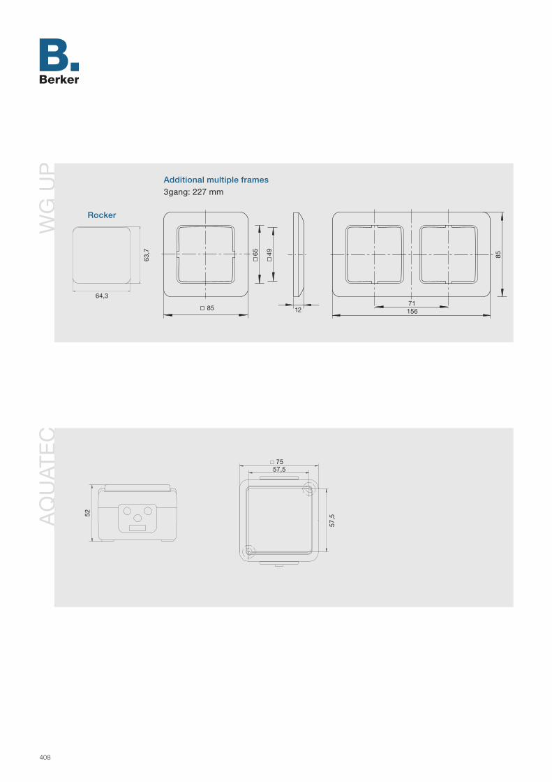
408
WG
UP
AQ
UAT
EC
Rocker
Additional multiple frames3gang: 227 mm
63,7
64,3
65
1285
49
71156
85
7557,5
57,552

409
dIMensIonal draWIngsB
.IQ B.IQ Glass, stainless steel
Push-button 1-3gang: at top Push-button 4gang: on right
Push-button with room thermo-stat and display 3-5gang
B.IQ Polar white
Push-button 1-3gang: at top Push-button 4gang: on right
Push-button with room thermo-stat and display 3-5gang
B.IQ Labelling fieldsfor push-buttons 1-3gang (left), for push-buttons 4gang (bottom left) and push-buttons 5gang (bottom)
labelable surface
labelable surface
88,516
,65
118,
1
88,5
88,5 3gang118,1 4gang147,7 5gang
31,1
88,5
88,5
15
118,
1
88,5
88,5 3gang118,1 4gang147,7 5gang
31,1
88,5
8,5°
151,61,3 5,
7
28,9
85 79,7
151,61,3 5,
7
28,9
114,
6
109,
3
151,61,3 5,
7
28,9
144,
2
138,
9
labelable surface

410
TS
SE
NS
OR
dIMensIonal draWIngs
76 31 93 160
48,5
86
71
138,
414
8,9
60
74,9
24,5
15
4
5,7
5
24,515
45,7
25,
6
7,5
5
31 93 160
8660
2737
71
138,
414
8,9
60
74,9
TS SENSOR
TS SENSOR wITh ROOm ThERmOSTAT

411
AAcknowledgement ................................ Feedback that an item of information has been received, understood and/or
processed.
Actuator ................................................ Device which executes control commands. It includes, for example, NO (normally open) contacts to switch consumers.
Address ................................................ Identification of devices on the bus, e.g. in the form of a consecutive numbering (see Group address, Physical address, Source address, Telegram, Destination address).
Addressing ........................................... The process in which a device on the bus is assigned a physical address and/or one or more group addresses.
Analogue value ..................................... An analogue value may assume an infinite number of intermediate values between a minimum and maximum, e.g. temperature, brightness, etc.
Application program ............................. The program which is loaded into a bus coupling unit or user module and defines the function of the bus device.
Application ........................................... Application program in a bus coupling unit. A push-button can be used, for example, for dimming or to control the shutters or window blinds. In ETS 2 the term “program” is used.
Area coupler ......................................... Provides the data link between a main line and the area line.
Area ...................................................... Multiple bus lines can be grouped with line couplers over a main line to form an area.
BBaud rate .............................................. Number of bits transferred in a specific time unit. The unit is bits per second.
On the instabus the baud rate is 9600.
Binary character, binary data ............... A value which can assume only two variables, “1” or “0”.
Bit ......................................................... Smallest unit of representation of binary data (binary digit). A bit can only assume the value 0 or 1.
Building systems engineering .............. Interconnection of system components and users over the instabus to form a unified electrical installation system, implementing functions and processes, and the systemic links between them, within a building. The intelligence is distributed across the system components. Information is exchanged directly between the devices.
Building visualization ............................ Visualization of the switching states of electrical equipment forming part of the building installation, on a PC monitor or touch panel. The program also permits remote control of the installed components.
Bus access method .............................. Organizational method by which each individual device accesses the bus to exchange information. The instabus uses the CSMA/CA (Carrier Sense Multiple Access/Collision Avoidance) method. It permits equal access privileges for the devices connected to the bus, with avoidance of collisions.
glossarY
412
Bus cable .............................................. Twisted-pair two-wire cable. Permissible cable types: PYCYM or J-Y(St)Y 2x2x0.8
Bus coupling unit (BCU) ....................... Forms the mechanical, electrical and data link between the bus (cable or data rail) and the user module.
Bus ....................................................... Transfer medium over which a number of users (devices) exchange information. On the instabus the transfer medium used is a two-wire cable or data rail. Apart from the information, the power to the electronics of the devices connected to the bus is also transmitted over the instabus.
Byte ...................................................... A unit of information comprising 8 bits. A byte can assume 256 (28) different values.
CCoupler ................................................. Bus device to provide the data link between, and to extend, lines and areas.
DData type .............................................. Determines the length of the telegram. An item of On/Off switching information
has a different telegram structure to an item of dimming information, for example.
Debounce time ..................................... Waiting time in order to avoid erroneous telegrams possibly caused by the repeated spring-back when a mechanical contact closes.
Decentralized system ........................... A system which operates with no higher-level central control. In a system of such a kind, the users/subsystems control the information flow, bus access, etc. themselves.
Destination address ............................. The address of the device on the bus which receives the information.
DIN rail .................................................. Rail executed to DIN EN 50 022, onto which appropriately designed DIN rail mounted devices (“RMD”) to DIN 43 880 are snapped. Dimensions: 35 x 7.5 mm (x modules).
EEEPROM/EPROM ................................. Electrically Erasable Programmable Read Only Memory. The data are retained in
the event of power failure.
ETS ....................................................... KNX/EIB Tool Software, non-proprietary program for parameter setting of KNX/EIB devices.
European Installation Bus Association (KNX/EIBA) ....................... Association of leading electrical installation companies with the aim of offering a
uniform, high-reliability installation bus system on the market.
Extra-low voltage ................................. Protective measures against direct touch contact to DIN VDE 0100 part 410. Umbrella term for: FELV = Functional Extra Low Voltage PELV = Protective Extra Low Voltage SELV = Safety Extra Low Voltage

413
glossarY
FFeedback .............................................. Indication that an item of information (command) has been understood and/or
processed and/or executed and/or the item of equipment concerned has changed its state.
Filter table ............................................. List stored in a coupler that decides which telegrams are allowed through and which are blocked.
Flag ....................................................... Accessory to an object. It decides, for example, whether the object status can be read over the bus.
Forced guidance .................................. Forced activation or deactivation of an actuator contact, without other devices being able to change the set switching state. When forced guidance is cancelled, the actuator can return to its original state.
Functions .............................................. Functions generally refer to the correlation between cause and effect, between input and output variable, or between sensor and actuator. The instabus provides the following functions: - Switching, loop control, measurement - Open-loop control, signalling, monitoring
GGroup address...................................... Address at which multiple recipients can be reached by one telegram. They thus
form a group. The group address is a function-oriented address.
hInterfaces .............................................. Defined points within a system or within devices. In the instabus KNX/EIB, for
example, the following interfaces are defined: - Between bus (cable or data rail) and bus coupling unit - Between bus coupling unit and physical external interface (PEI)
LLight scene ........................................... Specific lighting situation in a room with multiple lighting groups.
Line amplifier ........................................ Coupler which detects, based on its physical address, that it is to be used to expand a line.
Line coupler .......................................... Bus device to interconnect lines. Depending on the destination address, telegrams are forwarded via line couplers or limited to one line.
Line ....................................................... Part of an instabus comprising an electrical segment or created by the interconnection of electrical segments via line amplifiers.
Logic operation .................................... Combines the effect of different sensors on an actuator.

414
mMain line ............................................... Interconnects multiple line couplers and connects them where appropriate to the
assigned area coupler. Thereby permits data exchange across multiple lines and areas.
Module .................................................. A function group with defined, known properties, which may be either hardware (unit, circuit board) or software.
PParameter ............................................. Configurable settings of an KNX/EIB device. They can be used to define whether,
for example, pressing the upper rocker of the push-button triggers an On or Off telegram.
Physical address .................................. Unique identifier of a bus device in the instabus. The physical address contains the device, line and area numbers.
Physical external interface (PEI) ........... 2 x 5-pin connection between a bus coupling unit and a user module. The func-tion of the PEI is programmable, e.g. as inputs/outputs or serial data transfer.
Programming ........................................ In relation to the instabus this term is also used for parameter setting and addressing, e.g.: - Assigning addresses - Entering switching times - Entering logic operations - Defining threshold values
RRS 232-C .............................................. Designation of a standardized serial port; another is V.24.
SSensors ................................................ Devices in the system which record physical variables, process them and send
them as telegrams over the bus.
Serial data transfer ............................... Sequential information processing, i.e. the information is transmitted and received consecutively.
Source address .................................... The address of the device sending information over the bus.
System components ............................ Designation of devices on the bus which perform higher-level non-application-specific functions.
Software plug-in ................................... For an additional program provided for an instabus device. A software plug-in is started by calling up the parameters view within the ETS. This is a convenient facility for overall project control and parameter setting for devices, covering all functions.
415
glossarY
TTelegram rate limitation ....................... This parameter defines how many telegrams the device can send as a maximum
in 17 seconds. It prevents overloading of the bus time capacity.
Telegram ............................................... A bit sequence for transfer of an item of information from one device on the bus to others. In the instabus the telegram contains: - Control field - Address field with source and destination address - Data field - Security field with checksum - Confirmation field
Time functions ..................................... Switch actuator contacts can operate at a delay after reception of a telegram.
Time switch .......................................... Implements the so-called “automatic stairwell light”. When an On telegram is received the contact of an actuator remains closed for a certain period of time.
Topology ............................................... System layout/structure
Transfer rate ......................................... Number of bits transferred in a specific time unit. The unit is bits per second. The instabus KNX/EIB uses a transfer rate of 9600 bit/s.
Twisted pair .......................................... Twisted pair of wires
UUSB ...................................................... The universal serial bus is a port for connecting peripheral devices (mouse,
modem, printer, KNX/EIB data interface) to the computer. Up to 127 devices can be connected to one single USB port. In 2000, USB 1.1 was upgraded to USB 2.0. However, the KNX/EIB interfaces support both standards.
User module (UM)................................. Part of an instabus KNX/EIB device which is clipped onto or connected to a bus coupling unit.

416

417
Training and service
acquiring the know-how you need to make use of the advantages of KnX/eiB. Berker offers suitable theoretical and practise-oriented professional training, and cordially
invites anyone who would like to upgrade their capabilities to include KnX/eiB. in addition to the basic course, Berker also offers special advanced courses for KnX/eiB insiders.
Please address any technical questions to our KnX/eiB hotline at:
Phone +49 (0) 23 55/9 05 - 2 01
Feel free to ask our representatives directly about options for product training. Please contact the representative or Berker office nearest you.
information about representatives, contact persons and the download area with current data are available on the Berker website at www.berker.com
Please contact us directly if you have any other questions.
Berker gmbH & co. Kgdomestic sales
Klagebach 3858579 schalksmühle, germany
Phone +49(0)2355/905-0Fax +49(0)2355/905-112
Trai
nin
gS
ervi
ce

418
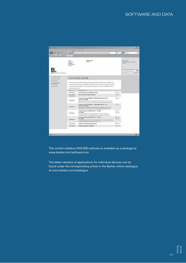
419
The current instabus KNX/EIB software is available as a package at www.berker.com/software-knx
The latest versions of applications for individual devices can be found under the corresponding article in the Berker online catalogue at www.berker.com/catalogue
soFTware and daTa
Trai
nin
gS
ervi
ce

Prin
ted
in G
erm
any
01
10
LBERKER THE RIGHT WAY.Berker is a family-owned German company that is aware of its tradition as well as an internationally recognized design brand. We have been manufacturing premium wiring devices and home automation systems in the Sauerland region of Germany since 1919. High-quality elegant products designed to last long-term as well as numerously awarded in design contests. Today our products can be found in some of the most exciting buildings worldwide. Soon perhaps also in yours.
Berker GmBH & Co. kG klaGeBaCH 38, 58579 SCHalkSmüHle, Germany
pHone +49 (0) 23 55/9 05-0, Fax +49 (0) 23 55/9 05-105 [email protected]
WWW.BERKER.com
Order no. 0300 65 / Version 6