inst dynnics of of tech full cambridge dept of · pdf filedynamics of .-2 full annular rotor...
TRANSCRIPT

AD-173 311 DYNNICS OF FULL NNULAR ROTOR RUB(U) NSSCHUSETTS 1/2INST OF TECH CAMBRIDGE DEPT OF OCEAN ENGINEERING5 J STACKLEY JUN 96
UNCLASSIFIED F/G 20/11 IL

.
.60.
.2
11111 4 .6 j%
,.
NAINj89A ~SA[AD 6MICROCOPY RESOLUTION TEST CHART
'.
N O BN4.J

........ . ." . . .. . . . . . . . . . . . . .
ii '
I I')
* cv.) Li
rlr
* of"
N _79
1YL
''4,*

DYNAMICS OF .-2FULL ANNULAR ROTOR RUB
by
SEAN JOSEPH STACKLEY --B.S.M.E., United States Naval Academy
(1979)
SUBMITTED IN PARTIAL FULFILLMENT -_OF THE REQUIREMENTS FOR THE
DEGREE OF
OCEAN ENGINEERand
MASTER OF SCIENCE IN MECHANICAL ENGINEERING
at the
MASSACHUSETTS INSTITUTE OF TECHNOLOGY "TE.D
June 1986
Sean Joseph Stackley 1986 ..-. "
The author hereby grants to M.I.T. and the U.S. Government permission toreproduce and to distribute copies of this thesis document in whole or in
part.
Signature of Author S"_,41_Depar ment o cean Engineering.. ' " I ay 1986 .
Certified byP O essor Stephen CrandallT Thesis Supervisor
~k;: ,.
Certified b ._".."__-'Professor J. Kim Vandiver
Thesis Reader
4 ~Accepted by V 'Professor A. Doug 1hael, Chairman
Ocean Engineerin Department Graduate Committee
Accepted by _ _ _ __ _ _ _ _Professor A.A. Sonin, Chairman
Mechanical Engineering Department Graduate Committee
-This d-'- .-e rt has bees pow v, ..

-2-
DYNAMICS OF
FULL ANNULAR ROTOR RUB
by -..
SEAN JOSEPH STACKLEY
Submitted to the Departments of Ocean Engineering and Mechanical Engineering .,
on May 1986 in partial fulfillment of the requirements for the degree of
Ocean Engineer and Master of Science in Mechanical Engineering.AL
ABSTRACT LA
Four modes of possible rotor motion are defined: synchronous preces-sion (without rub), partial rub, full annular synchronous rub and reversewhirl. A model is developed to investigate the relationships between arotational system's characteristic parameters and the conditions of equili- ..
brium for the full annular rub motion. The dynamics of an unconstrainedrotor with unbalance are first established. The impact of constraining therotor's motion by a rigid casing with a finite clearance is then analyzed.For any given system, the speed regimes in which full annular synchronousrub is in equilibrium are defined as a function of the system's unbalance, .-
clearance, rotor stiffness, damping and the coefficient of friction between '
the rotor and casing. The rigid stator restriction is subsequently allevi-ated and the equilibrium conditions for full annular synchronous rub arereanalyzed. Additionally, reverse whirl as a possible stable mode of rotormotion is studied. Specific rotational systems are then analyzed according
to the model developed to demonstrate tne effect of varying particular .. *-
parameters. -
Thesis Supervisor: Stephen H. CrandallTitle: Professor of Mechanical Engineering
"a- ,p*" -
--..Ipy &AV,- -- - - - -
-3- -_
lkACKNOWLEDGEMENTS
The author wishes to express his gratitude to Professor Stephen H.
Crandall for his guidance and encouragement throughout the development of
this thesis. Also, the author must express his most sincere appreciation to
his wife and children for their encouragement and patience during the last
three years.
-, - --li
Ac esi For
WTISGAI
Unanllouor
I , 1'"
-'...' .
, .',"'
4<.-.;
j4'.
:.',...
4. . %'
O4 es I
*~--*' ~ ........... ~4'* -~.4 . 4 /..r
r- w.
-4-
TABLE OF CONTENTS
li,
Page-
ABSTRACT..................................2
ACKNOWLEDGEMENTS.......................... . .. ..... . . .. .. .. .....
TABLE OF CONTENTS.............................4
* LIST OF FIGURES.............................5
INTRODUCTION...............................7
SECTION 1. DEVELOPMENT OF THE MODEL...................10
SECTION 2. FREE-ROTOR DYNAMICS.....................14
SECTION 3. CONSTRAINED ROTOR DYNAMICS..................21
SECTION 4. DYNAMICS OF REVERSE WHIRL...................42
SECTION 5. NON-RIGID STATOR DYNAMICS..................49
SECTION 6. CONCLUSIONS AND RECOMMENDATIONS FOR FUTURE WORK ....... 72
REFERENCES................................75
APPENDIX A................................77
7..

LIST OF FIGURES
Page
1 ~ ~~~~~~~~~~~~~~~ Roou oe.......................1Figure Title
2 Rotor Rub Planar Model ............. ...... 13
3 Free-Rotor Free Body Diagram ............ .... 15
4a Rotor Displacement Versus Rotor Speed. ............ 19
'4b Phase Angle versus Rotor Speed ............. .. 19
5a Normalized Rotor Displacement versus Speed (No Rub) . . . . 22
5b Normalized Rotor Displacement versus Speed (Rub). ..... 22
6 Rotor Rub Free Body Diagram. ........... ..... 23
7 Rub Forces Vector Diagram. ............ ..... 29
8 Centrifugal Force Components .............. .. 29
9 Composite Force Diagram. .......... ........ 30
10 Rotor Modes of' Motion Outline. ............. .. 36
11 Amplitude versus Frequency (No Rub) .. ............ 37
12 Amplitude versus Frequency (Limited Synchronous Rub) ... 37
13 Amplitude versus Frequency (Synchronous Rub-Limited
Discontinuity. ............. .......... 38
14Amplitude versus Frequency (Continuous Synchronous Rub) 38
15 Rotor Motion Mode Diagram. ......... ........ 39
16 Reverse Whirl Free Body Diagram. ........... .... 44
17 Normal Force Plot (Limited Synchronous Rub). ..........48
18 Translational Rub Model. ............ ...... 51
19 Rub Condition -Case 1 .................... 55
20 Rub Condition - Case 2 ............... .... 55
21 Rub Condition - Case 3 ............... .... 56
% e~
-6-
Page
22 Rub Condition -Case 4................................56
23a Rotor-Stator Load Diagram. .............. ... 58
23b Rotor-Stator Displacement Vector Diagram ........... 58
2~4 Rotor and Stator Free Body Diagrams. ............. 59
P'- .'

-7-
INTRODUCTION
All rotating machinery have some practical degree of unbalance which
drives flexural vibrations in the system. These vibrations may be readily
calculated in terms of the system's mass, unbalance, rotational speed, %V
radial stiffness and damping imposed by the medium in which the rotating
element operates. Should the magnitude of the vibrations exceed the
physical constraints of the enclosure which houses the rotating element, the
potentially destructive phenomena described here as rotor rub occurs.
Shaft vibrations, misalignment, blade creep and thermal expansion are
some of the physical realities which precipitate design of a radial
clearance between the high speed rotor and surrounding casing in
turbomachinery. Theoretical efficiencies of the turbomachinery are reduced
though, by blade tip losses which result from the presence of the radial
clearance between the rotor blade tip and the casing. Demand for improved
system efficiency thus drives a reduction of the blade tip clearance and so
increases the likelihood of rotor rub. Rotor rub in fact may be a design ,.
condition and so accounted in the design by the use of abradable materials.
Prior to the occurrence of rub, the rotating element's dynamics may be
described as synchronous precession, driven by the system's residual
unbalance. If rub develops, it may occur over a fraction of the rotor's
precessional orbit (termed partial rub), or may persist over the full orbit
(full annular rub). Of these two conditions, full annular rub is
potentially more destructive and is the subject of this thesis. For further
information regarding partial rub, attention is drawn to reference [2-4].
Examples of full annular rotor rub occur with rotor blade-to-casing or
a.:?..
.. ~ ~~

-8- -
rotor-seal rub, as well as with a rotating shaft having clearance in a
bearing. [5] The rub introduces a reaction force at the rotor's periphery
which strongly influences the rotor's dynamics and may additionally excite
the casing (further referred to as the stator) into motion. The reaction
force may be broken down into its normal and tangential (friction) force
components; the two being linearly related by the coefficient of friction.
Friction may be moderated by proper lubrication (such as in the case of
bearing rub) as well as through suitable selection of materials. Other
design considerations or abnormal operating conditions may preclude these
preventiv( measures though, and so friction may take on a particularly
destructive nature. .
Friction is tne rcsistive force which acts tangentially at the
in'erfo utee, two surfaces in relative motion. By acting tangentially
... r* .r.s per4ne-y, it essentially establisnes a torque which counters
t : , irgut? torque for the rotating element. The result is either a
speed or d nigher input torque required to maintain a
The effect of friction on the mating surfaces is to cause a
S, b Icup and, in the very least, some degree of grinding wear and
deformatlion of the rotor and seal or bearing annulus. The more extreme case
e.1cornpisses catastrophic destruction of the machine. [2] Typically
accompanyirg these mechanisms is the annoying and often unacceptable
acoustic phenomenon due to frictional vibration instabilities known as stick
slip. Dynamically, the occurrence of rotor rub may destabilize the
synchronous precession of the rotor. If friction forces are of large enough
magnitude, the counter-torque developed may instigate a reverse whiri
condition wherein the precession is in a direction opposite to the direction
of rotation of the shaft. The nature of reverse whirl is such that the
\"-"-,
-9-
rotating element is subjected to high frequency alternating stresses which .
may lead to rapid fatigue failure of the shaft. [61
O-

-10-
1 .DEVELOPMENT OF THE MODEL
The characteristics of rotating machinery designed for the generation .
or transmission of power vary greatly with their particular application. An
exact analysis of the motion is extremely complex, but many meaningful
- results can be determined through employment of reasonable simplifying
assumptions in a single degree of freedom model. Even with these simplifi-
cations though, numerous variables are necessary to describe the motionZ-
involved. -
The model in this thesis is displayed in Figure 1 . The rotating
element consists of a central disk of mass, M, mounted symmetrically on a
laterally flexible but torsionally rigid, massless shaft of stiffness Kr
The snaft stiffness is determinable knowing the shaft's material type,
cross-sectional properties and length. Tine shaft is then supported at each
end by rigid bearings without clearance. The natural frequency of the
rotojr, 'N the freqaency of excitation at which resonance occurs, is given
by czr= /Kr 1 r. The rotor dikis enclosed in its casing, separated
radially by a symmetric clearance, rc, existing when the rotor is at rest.
(The effects of gravity are neglected in this analysis). The casing, or
stator, is characterized by its mass, M, and its mounting stiffness, K.
As in the case of the rotor, the natural frequency of the stator is given by
'N /K 3/M.s Damping is introduced for motion of the rotor and stator
respectively by the damping coefficients, D rand D s. It is the presence of
damping in both the rotor and stator which limits the magnitude of their
responses at their respective resonant frequencies. Damping also causes a
phase lag between the System's excitation and response. For ease of .o..%
analysis, the model has been ".compressed" in Figure 2 to a planar diagram
elmn.ossso4 eta iko asMmutdsmerclyo .'-'
laeal lxbe.ttrioal iimsls hfto tfns r 4
Th4.f tfns sdtrial nwigtesatsmtra ye -"""...".
-- .- -- 4- .- * .. .- .4 * 4=4.

~.4 . ~ .- , - . ~ * ... '-
with the element's dynamic characteristics represented as in a simple linear
resonator system: a spring-mounted mass with a dashpot in which the energy
of the motion is dissipated. Both radial and longitudinal symmetry are
implicit in this model.
'p.-.-
..-J,
'-°%
./'. -..
'p.,
. - . ..

D"° Ks
w A- J.°
Mr B
VF >K,__ ,___ .,..-.
K\
FIGURE L ROTOR RUB MODEL % **
-- k- ,- -- !'X. -- - s.-

-13-
4..
4Ks -4
rN
-4 ?
-r
-- -. "
FMLRE~~~~-4 2.R7R U LNA OE
% 4"
-14-
2. FREE ROTOR DYNAMICS
'
It is assumed that under design conditions, the rotor is driven at a
constant speed, w, independent of the external load applied. This assump-
tion essentially neutralizes the effects of fluctuations in the design load
due to damping or rub related friction. Under ideal conditions, it is
imaginable that the rotor is perfectly balanced. Thus when driven at its
design speed, the rotor center remains at the center of rotation; aligned
with the axis defined by the supporting bearings' centers. This idealiza-
tion is not realized in practice though, and to some extent, a residual
unbalance exists in the mass distribution of the rotor. This unbalance may
be depicted in the planar model by locating the mass center (or center of
gravity), g, at a distance 6 from the center of the disk. The effect of the
unbalance is to establish a centrifugal force acting upon the center of ."
gravity while the rotor is in motion. This centrifugal force, which is
proportional to the square of the rotational speed, acts as the driving
force for the rotor's dynamical motion.
An analysis of the motion of the free rotor (i.e., without displacement
constraints imposed by the stator) provides the baseline condition for which
the rub condition may be compared. The equation of motion for the free
rotor is derived by applying Newton's 2nd Law to the rotor:
(sum of forces acting on the rotor)
(mass of the rotor) x (acceleration of the rotor center of gravity).. -.
Referring to the free body diagram for the rotor, Figure 3, the forces which
must balance in the steady motion of the rotor are described in the
following:
.1°
'-"I
,-: 5.4

-15-
FII.
% .
% %
F 1 %
FIGURE~~ ~ ~ ~ ~ ~ 3.FE*4r,1R ~ DY IGA

1P__ M .,
-16-
a. Centrifugal Force - As described above, this force results from the
presence of a residual unbalance; i.e., the center of gravity does not
coincide with the center of rotation. The centrifugal force acts on the
center of gravity and is directed radially outward from the bearing axis
(stationary reference position about which the rotor precesses).
b. Spring Force - The spring (or restoring) force acting radially
inward on the rotor center results when the rotor center is displaced from
the bearing axis. It is assumed in this model that the spring force is a
linear function of the shaft stiffness (assumed constant) and magnitude of
displacement.
c. Damping Force - The damping force acts on the rotor center such ,--.'
that it resists translational motion by the rotor. The damping force is
assumed to be a function of the damping coefficient experienced by the rotor
in its particular medium and the linear component of the rotor's velocity. -
The nature of the rotor's dynamics readily lend the analysis to
description using complex variables. Defining zc as the time dependent4
position of the rotor's center, referenced such that z = 0 coincides withc
the rest condition where the rotor center is aligned with the bearing axis,
then the equation of motion may be written as: ...
[-D - KrZ] = M z (I)
4rc -r c rg9
where z gt) = the vector position of the center of gravity of the rotor.g
Furthermore, z (t) may be broken down into the vector sum:g
4i
z (t) = z t) + z(t)g c go
where z gc(t) represents the vector position of the rotor center of gravity
relative to the disk center. -
The equation of motion then becomes:
+s. +. . + ~. . .. . - + . .
. Y X - -A-
-17- - _ i
- K(z + .-Dz Kzr c gc r c r c
or,
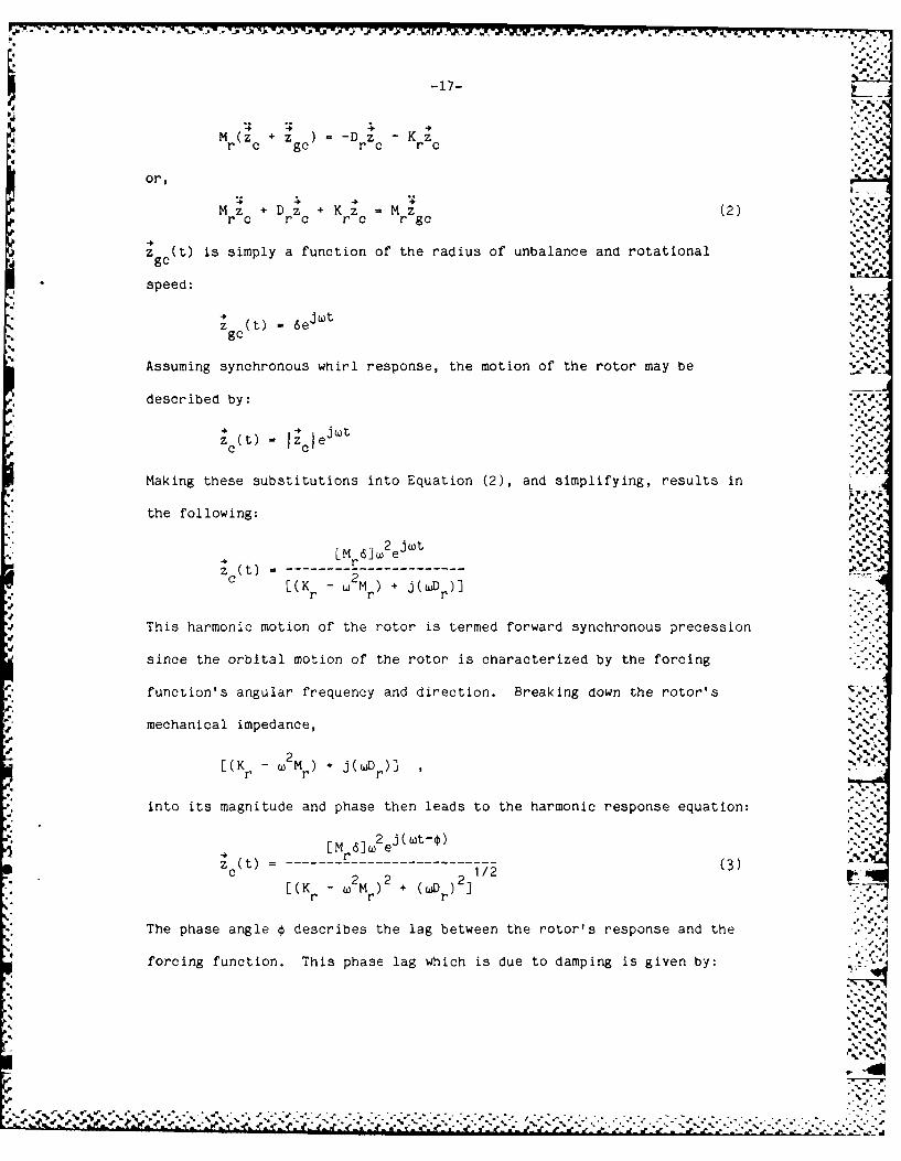
Mz + D z + K z - M z (2)rc r c r c r gc
zg(t) is simply a function of the radius of unbalance and rotational ,gc
speed:
j*4t
Zgc (t) = 6eimt
Assuming synchronous whirl response, the motion of the rotor may be
described by:
~j =
zc(t) JcIe j ~ :.:-
Making these substitutions into Equation (2), and simplifying, results in I ,
the following: -, -"
Z ( t) [ -Mr )----- -'
[(Kr M + j(wDp)]rr r
This harmonic motion of the rotor is termed forward synchronous precession
since the orbital motion of the rotor is characterized by the forcing
function's angular frequency and direction. Breaking down the rotor's -
mechanical impedance,
[(Kr - W2Mr + j(wD )] ' " ' "
into its magnitude and phase then leads to the harmonic response equation: "-"-.
[M 61W2e (wt-0)r t) = r (3) - - -"-c 2 2 212
[(K - W M ) + (wjr)2 .r r r
The phase angle 0 describes the lag between the rotor's response and the
forcing function. This phase lag which is due to damping is given by:
.,% ."
• . o o . o . .. . . . . . . . . . .. .- , .
""-' -', .% ' ':':;- """ ". "., , ", .".'V .,'--',-'.'-- .-.'..',-' -'--.-'.'. -,:'. ,:.-.-..-.-....-.... -'- "" - "--"- - - -"- " - -" "
S-,"-. ,', -. Z' ' ' {. .'r' r , f Lj j 2 - . . . ' . - .- .- , - .- . .- .

-18-
*tan r
(Kr -2Mr )
It is convenient to introduce non-dimensional variables into Equation
(3) for ease of future analysis. By defining a non-dimensional rotor speed
and damping ratio as given below:
B = WWD
2-KM% r r-
then Equation (3) may be rewritten:
2 jYwt-C)- -- - e (4)
B2)2 2/2"[(1 - B (2 ) '.-''
Similarly, the phase relationship may be rewritten:
tan-1 (1 - - (4a)
The plots of z c vs. a and 4 vs. B are typical amplitude and phase plots
for a second order system, such as those in Figure 4.
Consider the case of light damping, r << 1.0. At low speeds, i.e.,O ., temagnitude 2qain
<< I the of Equation (4) reduces to I cI . As the speed
increases, the displacement increases non-linearly until the maximum dis-
placement occurs at B - (1 - 2 ) 1/2
+ clma x 2 112.. ..
2 (I - ) - -
Here it can be seen that the maximum displacement is solely a function of
the radius of unbalance (directly) and the damping ratio (inversely).
Further increases in speed bring a reduction in displacement. For very high-"
speeds, i.e., B >> 1.0, the displacement approaches 6 (a constant).
1P
--"- ... -.

-19- :4-.
2.0- Rotor Diepicoermoet vs Rotor SpeedC. 2.o -0--
1.9-
1.4-
0.8-
1.7-1.6 . .
1.5 '-'
1.2
40.3
0.2-0.1
0.0"
0 1 2 3 4
ROTOR SPEED
18Phase Angle v Rotor Speed
170-160-150-140-130
S *
120-w 110-
10.-
0.3 , .,4
go-,
0.2 '- "- .'
50-
40 -%*~
30-20-
0.0 1 2 3 4
ROTOR SPEED
FZGLJRE 4Ca). ROTDR DI.&PLAMWHNT vs RDTDR SPEEI) (Top)FIGURE 402). PHASE ANGLE vs RoTOR SPEED (Botto.)
* O. '-
..'.-.Z,,,
13e'_..
-20-
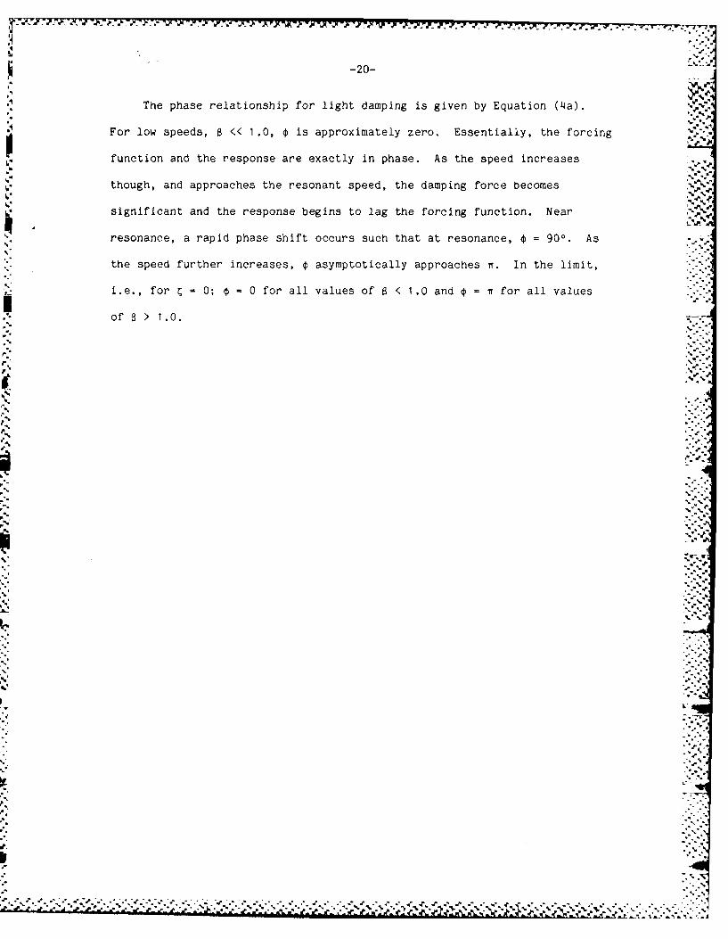
The phase relationship for light damping is given by Equation (4a).
For low speeds, B << 1.0, 0 is approximately zero. Essentially, the forcing
function and the response are exactly in phase. As the speed increases .,N %.
6- though, and approaches the resonant speed, the damping force becomes
significant and the response begins to lag the forcing function. Near
resonance, a rapid phase shift occurs such that at resonance, 0 = 900. As
the speed further increases, 0 asymptotically approaches n. In the limit,
i.e., for = 0; € = 0 for all values of B < 1.0 and = n for all values
of > > 1.0.
• .-,.
* .* ',. .-- °,*.9 %~. '°

-21-
3. CONSTRAINED ROTOR DYNAMICS , .. ,
As previously described, rotating machinery designed for the generation
or transfer of pow,-" are typically enclosed within a casing which minimizes
the clearance between the rotating element and casing. The dynamics of the %
constrained rotor motion may simply reduce to those of the free rotor as
presented in the preceding section if the rotor and stator never come into
contact. Tnis no-rub condition exists if either of two basic criteria are
in effect:
(1) Tne maximum amplitude of free rotor displacement, 1z , is lesscomaxp
than the constrained rotor clearance, or
(2) The rotor is operated within a speed regime, characterized by a
speed w, such that the amplitude of free rotor displacement, zc(), is
less than the constrained rotor clearance.
As will become evident through the following analysis, condition (2) above "
should be further restricted to speed regimes where w is less than the rotor
natural frequency, These two cases are depicted in Figure 5 using the
plot of amplitude vs. speed.
If in fact the rotor and stator come into contact, the dynamics may
become quite complex. The analysis will be first conducted with the
assumption that the stator is perfectly rigid (though this restriction will
be alleviated later) and only full annular rub will be considered.
The free body diagram for the rub case is presented in Figure 6. Prior
to contact, Equation (4) describes the rotor's motion. It can be seen that
upon the initiation of rub, the rigid stator limits the rotor's displacement
while introducing a reaction force, R(t), at the point of contact. This .

-23-
FIMURE~~~-. 6-R-, UBFE
IL .

-22-
Rotor Dlplacement v8 Speed (No Rub)2.0 -1.9 - ,'
1.7-1.6-
1.3 -
1.2 -5 1.1-= - 10o-----------------------------
1N 0.9
~"0.80.7-
r 0.6-0.5-0.4-0.3-0.2-0.1 -0.0,
02 3 4
ROTOR SPEED
Rotor Displacement vs Rotor Speed .-., ...-
2.0-
1.7-
4 1.7-
1.3-
* 1.5.
1.4-
10.3
10.2
0. 7 - ' "
0.8 - I"""-,
0.4 - ..,.,I
0.2 .',.
0.1 I
00-0 rv1 ~ 2 34
ROTOR SPEED
FIGURE 5(a), NORMALIZED RO7OR DISPLACEMENT vs SPEED (No-Rub) (Top)
FIGURE 5(b). NORMALIZED RO3TnR DISPLACEMENT vs SPEED (Rub) (Bottom)
,:--,:.-

-23-
9 CVt
F GU f RVT OR RUB FREE BODY DIAGRAM '

-24-
reaction force is comprised of a normal force and a tangential (friction)
force. Since the displacement is constant, the restoring force acting on .-"%a
the rotor is also constant (i.e., independent of rotor speed, w). As in the -- A
5,,.. ,
case of the free rotor, the equation of motion for the rub condition may be
developed from Newton's Second Law:
M z = -D z - K z - R(t) (6)r g r c r c
4 4 - , e wt,-'-."
Substituting z (z + z ) and R(t) = (N jN)e then Equationg gc c
(6) becomes (after rearranging terms):
M z + D z + K z = -M z - R(t)r c r c r c r gc
j .. tSince z = 6ej"t, then the above equation may be solved for z bygc c
assuming synchronous precession:
[M 6W (N + j N) J4 r e3~t(7
z (t) - - (7)a.c [(Kr - 2Mr + j()D r)].
By dividing through Equ3tion (7) with the radial clearance, rc, and
utilizing the previously defined non-dimensional speed and damping ratio
variables, Equation (7) is transformed to its non-dimensional form:
e e
Z c(t) E62_ j~t
r-- 2ece [(1 - 2) + j(2 6)]
Ac
where the new variables are defined:
= 6/rc
n = N/kr
The right hand side of Equation (8) is reduced to a magnitude and a phase in
the following rotor rub equation:
z (t) F 2_ )2 _( n2_] e~t- -.(C6__ j(Wt - -Y)
r - 122 (/ 2 (9)
- .2 2

-25-
where
= tan 1(EB2 - n)
The following observations may be drawn regarding the physical
implications of the rotor rub equation. The parameter 6 is a measure of the .,
rotor's unbalance, and as such is not designed into the rotor, but results
• . from manufacturing processes which are unable to meet with ideal design --
conditions. The value of rc though is designed into the system, and so jtolerances must be placed on 6 in order to ultimately control the value of
E, a measure of the rotor's displacement-to-clearance ratio. In the case of
the free rotor, any increase in 6 leads to a direct increase in the rotor's
maximum displacement. Since the maximum displacement is now constrained
though, a normal force develops at the interface between the rotor and
stator when the rotor's runout equals the clearance. The maximum normal
force developed thereafter is directly related to the value of e. Referring
to Figure 5, the normal force developed for rotor speeds less than the rotor "'.
resonant speed may be crudely estimated as the magnitude of force necessary
to compress a 'spring' of stiffness equivalent to the rotor's impedance a.,W
distance equal to tne difference between the free rotor's displacement and
the radial clearance. For speeds greater than the rotor resonant speed
( > 1.0) the characteristics of the combined rotor-stator govern the
system's behavior and a more detailed analysis is necessary.
Meanwhile, a frictional force, f - un, develops at the rotor-stator-'..interface in opposition to the relative motion between the rotor and stator.
The coefficient of friction, vi, depends primarily on the material types in .
contact and the degree of lubrication present. For unlubricated metal-to- .
metal applications, typical values of i may range from 0.1 - 0.3. [7] The
... e-

-.. 14 . 6 -V -
-26-
frictional force may be replaced by a force and a couple acting upon the
* rotor's center. The torque thus created acts as an additional load upon the
rotor's driving force. Equation (9) emphasizes the phase lag, ( +),
between the response of the rotor and the forcing function. 0 was defined ".
previously as the phase lag caused by the damping force in opposition to the ""4
linear component of the rotor's velocity and was given by the expression,
2= tan- I (2CB)/(I - B2). Y is the phase lag caused by the frictional force
which further opposes the rotor motion as previously given by:
Y - tan -1(n)/(B - n).
Since rub is presumed, the magnitude of the rotor's displacement is
exactly equal to the radial clearance (given a rigid stator). This
condition results in the magnitude of Equation (9) being equal to unity.
The independent variable in the equation is the rotor speed. The values of
, and c are assumed constant, and so the values of the normal force and
phase angle may be solved for any value of B. This arises from the I"-. condition:
Li 2_ n) 2 + ( n)l2 11/2 • -
2 2 21/2 -
( ---- + (2- 1
Following a few algebraic steps, the following quadratic equation in n is
derived: "''
( 2 2 2 2)2 2 2 4(I + V2)n + 2(1 - B + 2;ap)n + [(1 + (2GB) B 284] = 0 (10)
" which when solved yields the relationship for n as a function of B:
2 2+ 2 2 22 2 2 4
-' la2
(1qu) (11) "
- ~Equation (11) indicates two possible solutions for the normal force.'-"-
S..
.. 5
. 5 . . p .*..... .. .. ... . -'-- - - .. " ' '- *;, , ','--, . .;,_ " " .. . .-. '.
-27-
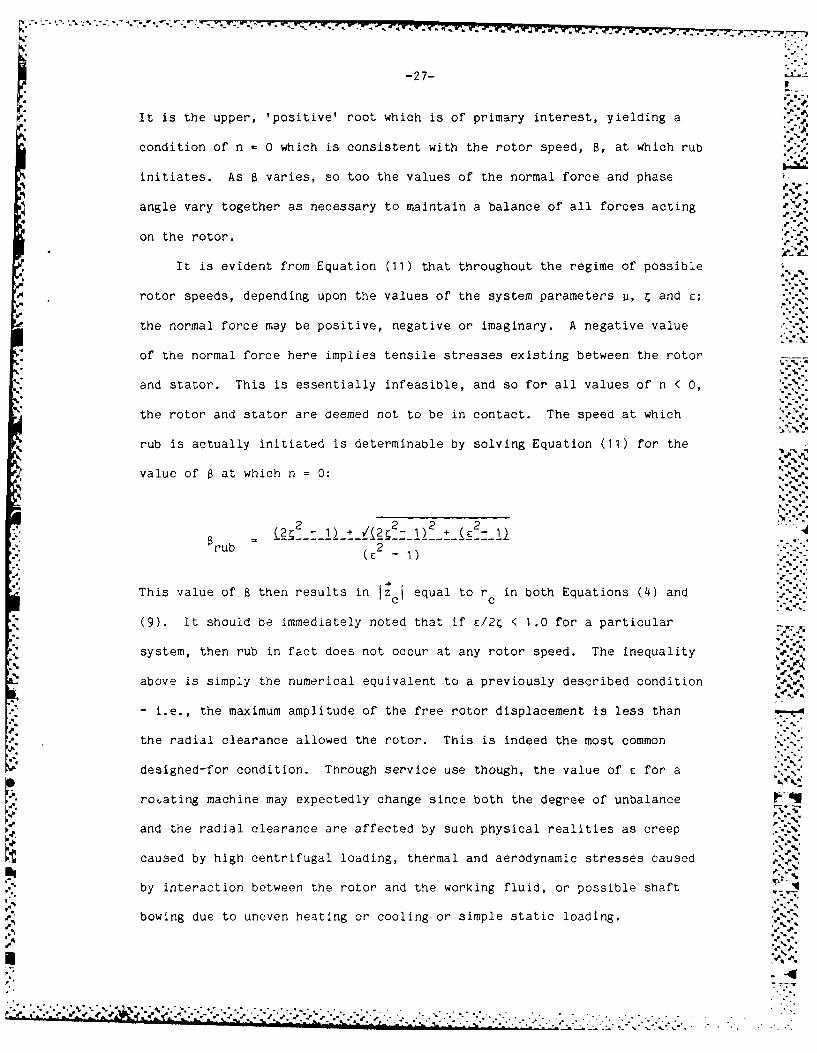
It is the upper, 'positive' root which is of primary interest, yielding a
condition of n 0 which is consistent with the rotor speed, B, at which rub
initiates. As B varies, so too the values of the normal force and phase
angle vary together as necessary to maintain a balance of all forces acting
on the rotor.
It is evident from Equation (11) that throughout the regime of possible
rotor speeds, depending upon the values of the system parameters p, and C;V.-
the normal force may be positive, negative or imaginary. A negative value
of the normal force here implies tensile stresses existing between the rotor
and stator. This is essentially infeasible, and so for all values of n < 0,
the rotor and stator are deemed not to be in contact. The speed at which
rub is actually initiated is determinable by solving Equation (11) for the
value of at which n = 0:
rub 2 2 2
This value of B then results in zi equal to rc in both Equations (4) and
(9). It should be immediately noted that if /24 < 1.0 for a particular
system, then rub in fact does not occur at any rotor speed. The inequality
above is simply the numerical equivalent to a previously described condition
- i.e., the maximum amplitude of the free rotor displacement is less than
the radial clearance allowed the rotor. This is indeed the most common
designed-for condition. Through service use though, the value of e for a
ro.ating machine may expectedly change since both the degree of unbalance .-1
and the radial clearance are affected by such physical realities as creep
caused by high centrifugal loading, thermal and aerodynamic stresses caused
by interaction between the rotor and the working fluid, or possible shaft - I
be.ebowing due to uneven heating or cooling or simple static loading. **,.
'4"
- 4 . . . , . 4
o.~

r°,l .. .
-28-
It is the intent of this analysis to determine the behavior of rotating
machinery as the rotor speed is increased beyond the rub speed for systems
where e/2 > 1.0. Figure 5(b) provides a simple plot of the amplitude vs.
speed relationship for the rotor. It is known that for 8 <ru Equation
(4) describes the rotor's motion. Furthermore, for rotor speeds within the
regime a < B < a', it is assured that the rotor and stator will be in 'Arub
contact with the normal force given by Equation (11). For rotor speeds j. !
greater than 8' though, Figure 5(b) can only provide basic insight into the
problem. It was alluded earlier that while the rotor is undergoing a full
annular synchronous rub, then it is the characteristics of the combined
rotor-stator which govern the system's performance. This performance may
best be analyzed by investigating the normal force and phase angle
experienced by the rotor.
Equation (11) for the normal force may be rearranged algebraically to
yield the following expression:
21/2/ 2•[(1-8 2 ) + v(2C6)] + (lI+'2 ) /(e82)2 --[ -I2---2--2:'
n ----------------------- (12)Tetrepsilremeof(1 + u )2£'.,
The three possible regimes of n (positive, negative or imaginary) may be ,'."
examined through this equation. It is instrumental to first analyze F, the
sum of the external forces acting on the rotor center, by resolving it into
orthogonal components (see Figure 7) - those forces acting parallel to zc
(designated the radial or r-direction) and those forces acting normal to
zc (designated the tangential or t-direction).
F is further resolved into a component due to rotor displacement and
a component due to the mass eccentricity itself in Figure 8.
By combining the non-dimensional relationships in Figures (7) and (8),
I.-.- -

-29-
,A nn an
FccKrrKrr c 1
c.
FIGURE 7. RURS FORCES VECTOR DIAGRAM
m'
K, r.
FIGURE B. CENTRIFUGtAL FORC:E COMPONENTS

-30-
AnA
F~ 77
n
oc.Fe
c?.
Kr
FIGUJRE 9. CCNFQ=TE F13RCE DZAGRAi
% % %Ij .

-31-
a geometric interpretation for the relationship between forces in Equation V
(11) is attained in Figure 9.
By applying the Pythagorean Theorem to Figure 9, the variables become
related by:
2 2 2 2 2 (3( 2) (2 a + pn) 2 + [(I +2 n]2 (13) , .
Physically, this states that:
[the component of centrifugal force acting on the rotor center due to mass
2eccentricity], c8 , is balanced tangentially by [the damping and friction
forces], and radially by [the normal and elastic forces lessened by the
centrifugal force acting on the rotor center due to rotor displacement]. By
solving for the normal force itself, Equation (13) yields:
n -( - 2) + {(o2)2 - (2r.8 + jn) 21/2(14)
The parallel between this equation and Equation (12) is immediately
apparent. The following generalizations may now be drawn regarding the
nature of the normal force as a function of the remaining system parameters
and variables:
' (a) As the rotor speed increases:
(i) The normal force, n, first becomes positive when:
22 - 22 + (28)2
This simply states what was earlier determined; that rub initiates when the
magnitude of the centrifugal force due to mass eccentricity equals the
rotor's impedance multiplied by the radial clearance. A
(ii) The value of (82 - 1) increases; which tends to increase the 5
normal force.
.N 2(iii) The value of the centrifugal force, (c2) increases; which will
increase tne normal force if tne phase angle, , is less than 900; and will
decrease the normal force if 0 exceeds 900.
"- -% ,
......- ..- _ ..... .. S S * - .> -- '. : . iJ '; ;; "

-32-
(iv) The value of the damping force, (2GB) increases; which drives the
phase angle towards 900. For values of 0 less than 900, this means a
reduction in normal force, and obversely, for values of > 900 this .
translates to an increase in normal force.
reuto•nnra ocadovrey fo vlusof 4>9Q ti
(b) Any increase in the damping ratio, , or friction coefficient, i, will
increase the tangential forces, and in a manner similar to (iv) above will
drive the phase angle towards 900. Again, for values of * less than 900,this means an increase in normal force, and for values of 0 greater than
900 , this means a reduction in normal force.
(c) The center of gravity of the rotor will orient itself to that phase
angle necessary to balance the forces acting upon the rotor. This assumes
that there is in fact some angle which will satisfy this dynamic
requirement.
If for a given rotating system characterized by the parameters i, and
c operating at a particular speed B; there is no value of the phase angle
which will cause the forces acting on the rotor to balance, then the
assumption that the rotor is precessing at synchronous speed is no longer ...
valid. When this case arises, i.e., when the radical term in Equation (12)
becomes negative and n becomes imaginary, an alternative mechanism for the
rotor motion must be determined. The 'equilibrium criterion' for
synchronous rub may thus be stated mathematically:
00*0 ,' , ".
09,14o .. % -
2 +(B 2 ) 2 2--- i no t ? oss b0 (15)
then synchronous rub is not a possible mode of rotor motion.

-i
-33-
The multiplicity of rotor speeds (roots) which make the radical term in
Equation (15) identically equal to zero lead to three possible sequences of
rotor modes of motion occurring within the rub regime:
(i) If all the roots to Equation (15) occur at speeds below the speed
at which rub initiates, then a real solution to the rub equation exists for
all rotor speeds. This does not preclude the possibility that rub may cease
(i.e., n < 0), but rather indicates that the rotor dynamics will be governed
by the relationships previously developed for synchronous whirl (i.e.,
Equations (4) and (12)). .
(ii) If one of the roots to Equation (15) occurs at a speed greater than
the rub speed, then the rub equation has no solution for rotor speeds
greater than this limiting speed B1. It is possible that B1 could occur at
a speed for which rub is not in effect (i.e., the normal force is less than
zero according to Equation (12)). This condition shall be discussed in
greater detail in a later section.
(iii) If two of the roots to Equation (15) occur at a speed greater than
the rub speed, then there is a limited regime within which synchronous rub
is not in equilibrium. For all rotor speeds less than the first root and
greater than the second root, the rotor dynamics may be described by
Equations (4) or (12). Otherwise synchronous rub is not a possible mode of
rotor motion.
Throughout the speed regime in which synchronous rub is not a solution,
three modes of rotor motion are possible - either a forward synchronous
whirl without rub, a partial rub or a full annular rub reverse whirl. These
cases shall be discussed in greater detail in the following section. In
order to provide clarity on the interrelationships of these various modes,
C~~~. .- .- .. ..

, '-a..-%
I-34-
the outline in Figure 10 provides a sequencing of the possible system
dynamics as a function of rotor speed. It is informative to demonstrate
these various modes by comparing the amplitude of displacement and normal
force experienced by the rotor as functions of rotor speed as in Figures 11 -..
through 1 4. '''
i) No rub
Tne reference case is the simple condition that rub never occurs. This ."-7:
is true for systems where c < 2 . As can be seen in Figure 11, the radial
clearance is greater than the maximum displacement experienced by the rotor
and so the normal force is zero for all speeds.
(ii) Limited synchronous rub
As depicted in Figure 12, rotor rub initiates at some speed B < 1.0.rub
Further increases in rotor speed drive the rotor hard against the stator
while the normal force steadily increases. The large friction and damping
forces which also develop ultimately disrupt the synchronous rub. Further
increases in rotor speed do not lead to a restoration of rotor rub but
rather follow the course of action for the free rotor. %
(iii) Synchronous rub-limited discontinuity
Similar to the limited synchronous rub case, rub initiates at a speed
B < 1.0, and ceases at some speed, BI. At Bi, rotor precession jumpsrub I
down to the free-rotor synchronous whirl. As shown in Figure 13, at a yet
higher speed, dynamic conditions once again become favorable for a stable,%J6
synchronous rub. At this speed though, some perturbance is required to
bring the rotor into contact with the stator and thus initiate the rub. It
I"%
a..

-35- -,'
must be emphasized that reverse whirl may also be stable at this speed '
(dependent upon the slip condition), thus making it difficult to predict the
exact motion which would ensue.
(iv) Continuous synchronous rub
As in the limited rub case, rotor rub initiates at some rotor speed, I-"
ru < 1.0. As rotor speed is further increased, the rub reaction forcerub
also steadily increases. In this case though, the damping and friction
forces are not significant enough to disrupt the equilibrium of the
synchronous rub (see Figure 14).
Analytically, regimes where the various modes dictate the behavior of
the rotor may be defined and mapped onto a family of curves using variables
thus far defined. Figure 15 depicts the impact on rotor motion of varying
the coefficient of friction, unbalance (or inversely the radial clearance),
or speed ratio for a fixed value of rotor damping. For this particular case
of C - .10, region (i) of the plot depicts the condition for which no rub
occurs (independent of the rotor speed) and is described by the inequality .
of E < 2r. For a particular value of E > 2C, rub first initiates at the
speed defined by the previously derived relationship:~. .?-*-'
ru 2 2Brub ( 2- 1 ) . £
This value provides the lower bound to region (ii) in Figure 15. Region
(ii) depicts the speed regime wherein synchronous rub is in equilibrium. If
we consider the specific case where the coefficient of friction, o - 0.25,
then region (iii) depicts the speed regime where synchronous rub has fallen

-36-
-V
SK)WT RUTATN
UNDALACE -SYWMNWJ VjURJ
RESTJNG VURCE
FREE rT1DDR
CDCL FZFLfL ANLRR A
cvrrm= RM 4 SWI IM 1 RUN
To SYNCH WHIRL IJJWPT DEIVNVmrr RUB TD SYNCH VKUL
vrn=R_
ZYi WHIRL SYNCH VIRL SYNCH MBE SYNCH RMvrnc3rr RL wnVrTHXm RrESIALmSAIVt
ME RIT SOO0MFT3 II A7 ALL S1AE
TD
TD
RU) I
FIGURE 10. RDITUR M13DS OF PT11DN MnUTNE
2!].

-37-
Rotor DIaplocernent v3 Speed (No Rwb)2.0- .,
1.9 -",1.51.7-
1.6 ..
1.41 .,..-." %
w 1.2 -L.) 1.1 -0 1
M 0.9
S 0.50.
*"0.7
0.2n- 0.4 +
0.2 . .
0.1-
0.0-0 1 234
ROTOR SPEED
Rotor Displacement vs Rotor Speed
2.0"1.9I.-
1.7.-r
1.5N1.4 -
Wi 1.23L .2-
0.9S . 1.0 - I \'
0.5-0"(.7 - "%
0.5-0.4-0.3
0.20.1
-a.-00
0 12 3 4
ROYTOR 21PEED
FIGURE 1L AMPLITUDE vs; FRE8UrNCY (No Rub) (Top)FIGURE 2P. AMPLITUDE vs FREQUENCY (Llrted Synchroftous Rub) (Eotto...
• '-p-
-a -i.' -a.
. -. °a "
': . " "%; "" J " " .'',' . . .- ". "- -". . - . . '+ .- .. '" .- .r - . . . - ' ." - .. '.,..-' .% ... ' .'. '... ' -% . .,- . .. % ."." .'-" . '..."""--
. " " % % • ." .a. . ..-. . . . . ..'.-. .-. .,. ... .-" " .a..•.-. 'i-% .---.'-'m" - . -+ .% -d'. .,_[T.x' 'm - - d*-'

-38-
Rotor Disploceen.t vs Rotor Speed2.0-1.9 -. .1.8
1.7 -1.6-
1.5-
1.4 -i
1.3-
0.-
U.J I * .A .'.A:
0.1
.1.0
S 0.9 I-
1 .8 -
- 0.7 -: 0.6-1
0.5 -.0.8 -.
0.7-
0 1 2 3 4
R0)T0F SPEED"'""
?...,..Rotor Oluplo~emerit vs Rotor S peecd../.
2.0 ."-,-
1.9 -j.
1.6-
0.5-
1.4-1.3-1.2-
0.9
S 0.8
0 0.28
*- 0.4 -'' '
0.3 -". .
0.2 - '-.-.,0.1 - ' " -
0c1 2 3 4 --.
ROTOR SPEED
FIGURE *3, AMP'TUDE vs .FRE.- ZLEJ',Y CSynch Rub-LWJ -td DI sC-T" ,y) CTcp)
FIGURE 14. A$PUrTUDE vs FREGUE ZY (Contmnous Synch Rueo) Cbottol.)
.*.%,---.-:.
.- '-~~~~.,.-.'..-v.-.--"... ... -...........-............... . . ..

-~~~~ %.~ ~~
z
C- D
CSC
044
LLJ
z L)
CC
.0'
0 ni CD
ad. L Li I'aJ ~Ct.-
A.,
-40-
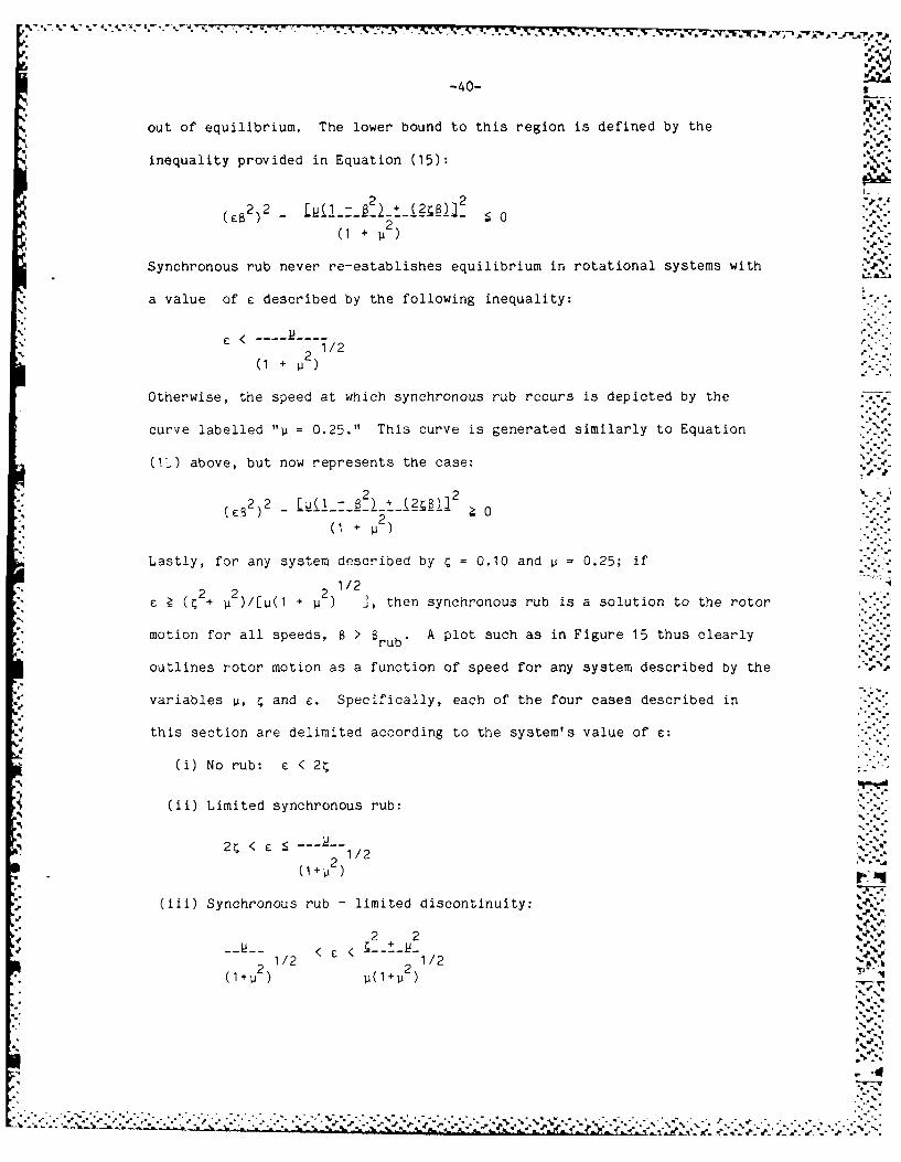
out of equilibrium. The lower bound to this region is defined by the
inequality provided in Equation (15):
2 2 2 2( ) ((1 + U2) . -
Synchronous rub never re-establishes equilibrium in rotational systems with
a value of c described by the following inequality:
E < 1/22(1 + 2)
Otherwise, the speed at which synchronous rub recurs is depicted by the
curve labelled "Ip = 0.25." This curve is generated similarly to Equation
(1:) above, but now represents the case:
2 2(82 2 ( >0
2( 1 i 2)
Lastly, for any system described by C = 0.10 and i 0.25; if
1/2> ( + )/[I(1 + ], then synchronous rub is a solution to the rotor
motion for all speeds, B > rB" A plot such as in Figure 15 thus clearlyrub*- .
outlines rotor motion as a function of speed for any system described by the
variables i, C and e. Specifically, each of the four cases described in
this section are delimited according to the system's value of E:
(i) No rub: E < 2'
(ii) Limited synchronous rub:
2 < -- "" 11221/ 2 ,..-(1+P
2 )
(iii) Synchronous rub - limited discontinuity:
2 2--U-- /2 < E < -+ -1/,,,""'
212 1/2(I+W2 2.1 +. 2 )

*-41-
(iv) Continuous synchronous rub:
2 2
l% I(1+~ )2/I~ a.
The relationships above explicitly indicate the effect on the rotor's mode
of motion of altering any of the variables involved.
JN.
V.,.°-° -
"5%
|S
I -
;.::;
S1N
S.lp
-. '-°
p.11
..5"i
a al

-42-
4. DYNAMICS OF REVERSE WHIRL
Reverse whirl is the state of rotor dynamics wherein the direction of
precession of the rotor center about the bearing axis opposes the direction
of rotation of the rotor about its own center. It was shown that in the*.'..-
absence of rub, an unbalance in the rotor's mass distribution results in a ,
forward synchronous whirl of the rotor. The presence of damping resists
this forward precession and thus creates a phase lag between the rotor
center as it precesses and the mass center as it rotates. This damping _
force though, is linearly related to the whirl speed and so can not by
itself destabilize the precessional motion of the rotor. When rub occurs, a
frictional force at the interface between the rotor and stator develops p
which combines with the damping force to oppose the rotor's forward
precession. Unlike the damping force though, the frictional force is a non-
linear function of rotor speed. If the additional force created by the .
frictional force opposing the rotor's forward whirl can not be balanced by
the tangential component of the centrifugal force associated with the
rotor's mass unbalance, then the synchronous whirl assumption breaks down.
The dynamics of the reverbe whirl problem are far more complex than for
forward synchronous whirl. Since the whirl speed, Q, is now independent of
the rotational speed, w, it must be introduced as a new variable in the
analysis. This then creates the additional complexity of having a phase
angle which is now a function of time (more specifically, a function of
(w - Q)t). Since the phase angle varies regularly with time though (i.e.,
constant frequency), a simplifying assumption is that the time averaged, or
net position of the mass center of the rotor is located at the centroid of h
the rotor (i.e., 6 = 0). Furthermore, since the whirl and rotational
16--
$,.

-43-
directions are opposed, then the direction of relative motion at the point
of contact (designated point A) between rotor and stator must be determined.
The velocity of point A may be written: 6
V -V c VAc
where IV 0=- rc = linear velocity of the rotor center
IVA aw = linear velocity of point A relative to the rotor center
- .
where a - rotor diameter
By assuming (aw) > (r Q), then the linear velocity of the rotor at A may bec
assumed in the direction of the rotor's rotation and the friction force is
thus aligned with the direction of whirl.
The free body diagram may now be analyzed to determine the conditions
whereby reverse whirl is possible. Figure 16 displays the forces at work
and their assumed orientation for reverse whirl. By considering the balance
of forces in the tangential and radial directions, two independent equations 5-.'.
are developed. In the tangential direction, the friction force is balanced % \ :
solely by the damping force:
.N = D (r Q)r c
By defining p = Q/w and substituting non-dimensional variables: 5 5
n - 2 Bp (16)
In the radial direction, the centrifugal force of the rotor is balanced by
the elastic force of the rotor plus the normal force between the rotor and
stator:
2M r Q N + K rr c r c.
In non-dimensional form this becomes:
2 2
The rotor rotational speed, w, and whirl speed, Q, may be kinematically
: I:e C:
.4.
''"" '''', ''' ' " ''' "' '-'',,' ''-''" ". 4" "., ".," "" .''..............................................-.........-..-...-.-..".........- "' " " .. "".....

*PWo -7 077W77 F
-44-
%.r
FD
4-
4 4d

-/45-
related through the slip condition that exists at the rotor-stator
interface. A no-slip condition would yield the kinematic relationship
common to epicyclic gear trains:
= (a/r )w
c
If there is slip at the interface, the whirl speed is reduced accordingly.
The slip ratio, s, is thus defined as the ratio of the (rotor whirl speed)-
to-the- (rotor whirl speed without slip); i.e.,
s- (a/r )w
Equations (16) and (17) may thus be rewritten:
pn = 2CB[(a/r )s] (16a)c
[s(a/rc)]282 = n + I (17a) .-
By substituting (17a) into (16a), the critical condition for reverse
whirl is determined:
{(a/rc)2S2]82 - 1} = 21, [(a/r )s]
The above condition may be resolved into a quadratic equation in B:
,(a/r c)S22 - 2 [(a/r )S] - = 0 (18)
Solving for 6 yields the critical speed above which reverse whirl is
possible:
2 2)1/2
---]-[------ (19) %rev a s --
The lone unknown variable in the above equation is the slip ratio, s,
which may in fact be difficult to determine. The limiting case arises of
course when no slip is present (i.e., s = 1.0). If it is assumed that the
damping and friction are of the same order of magnitude, then a is of the
order of r /a, which in general is much less than unity. The limiting casec
thus states that reverse whirl is possible for essentially all rotor speeds
-6..

- --
of interest (i.e., within the rub regime). It is not until a significant
degree of slip is present (i.e., s is of the order of r /a) that the minimumC
possible speed for reverse whirl may become restrictive on the behavior of a
rotor undergoing full annular rub.
Since the rotor first assumes a forward synchronous precession though,
it will continue with this motion until either it becomes unstable or is
perturbed into another stable mode of motion. As previously developed, the
forward synchronous whirl without rub is continuously stable as long as the
displacement of the free rotor is less than the constrained rotor's radial
clearance. The only mode where synchronous whirl may be destabilized then,
is during a synchronous rub. This has been analytically developed and
occurs if the reaction force between the rotor and stator becomes imaginary
or if the equilibrium state for the rotor-stator is inherently unstable.
In this situation, the equations developed based on synchronous whirl are no
longer applicable.
A qualitative analysis of the transient state following destabilization
of the synchronous rub proves quite meaningful. It may first be reasonably
presumed that the rotor will assume either a partial rub or a forward
subsynchronous whirl following the destabilization. Considering the latter
mode of motion, the impact of the non-synchronicity on the rotor's dynamics
is primarily that the phase angle, , is now a time dependent variable. The
centrifugal force which has been pressing the rotor against the stator
throughout the full annular rub now has a fluctuating component. As the ..
phase angle approaches 1800, the centrifugal force acting on the rotor
center due to the mass unbalance is actually joining with the spring force
to drive the rotor center in towards the bearing axis. The normal force
rapidly drops to zero and contact is broken between the rotor and stator.
• "N"-V "",."""5 "- ""' '" -"•"."-" -" " -"'."""" ' " - -- . . """, . "".", " '; .".- -"."," "" " " ' - . -

-47-
This may be somewhat anticipated by observing the near-vertical negative
slope of the corresponding normal force plot at the critical equilibrium
speed (see Figure 17). Now that rub is no longer present, there is no force
to drive a reverse whirl, and so the rotor will jump down to the stable mode
of forward synchronous whirl without rub. Perturbing the rotor back into
contact at this speed (or higher) may now provoke a reverse whirl. In the
previous section, the possibility for a restabilization of synchronous rub
was demonstrated. Under these conditions, either synchronous rub or reverse
whirl may result when the rotor is perturbed back into contact with the
stator. In general, no smooth transition can occur from a synchronous whirl
to a reverse whirl since this would mean transiting through a regime of zero
whirl speed. The whirl speed though would not drop below that necessary to
maintain rub-contact; for when contact is lost, the rotor either assumes a
partial rub whirl or resumes a synchronous whirl without rub.
The behavior of the rotor when transiting from a higher to a lower
speed differs markedly from the behavior of the rotor as it is increasing
speed. In the absence of some outside perturbation, when reducing speed
from a situation of synchronous whirl without rub at a speed, 6 > 1.0; no
jump phenomenon in the rotor displacement curve would occur, but rather rub
would occur only within that region of Figure (5b) where the free-rotor's
displacement exceeds the rotor radial clearance.
4.4
-4. . " . . "% "% ° , "% -% ' -% ' . ° ,. ' " .. ° . • ,- .° , " " . % " - °•. °"°", -. -o %

-48-
.Rotor OtsplaremeMt ve Rotor Speed1.0
1.7-1 . 7 .,
1.4-1.3-1 2
. - .'1,2-
0 . 0 --" "
0.5-
0.7-0.6-0.5-0.4-0.3-0.2-0.10.0 ' ',. .,;
0 2 3 4ROTOR SPEED
Normal Force ve Rotor Speed
0.4-
0.3
U-.....S
A? 0-
z
-0 .2, ' ., .
-0 .3 ',..
-0.4-
* -0.5 , ,a 0.2 0.4 0.6 0.8 1 1.2
Beta (&peed ratio)
:IGURE 17. NORMAL FORCE PL1T (Lvted Synchronous Rub)
, if-.':
I ..**%4 4 *.* -2 1

-49-
5. ROTOR RUB WITH A NON-RIGID STATOR
The assumption of an ideally-rigid stator enclosing the rotating
element in this analysis is not feasible, but depending on the stator's
dynamic characteristics, such may be an entirely satisfactory assumption for
the analysis. In this section, the stator is assigned a finite mass, radial
stiffness and damping coefficient. For ease of analysis, these characteris- -.
tics are assumed to be axisymmetric. Additionally, the stator is assumed to
be torsionally rigid. It is often instrumental to investigate the
translational system analogous to the rotating system under analysis. This
is first accomplished to provide insight to the complex equations developed
in the final analysis.
The basic precept in analyzing the coupled rotor-stator system is that 4.
once the state of continuous contact is interrupted, the synchronous full *,
annular rub condition will rapidly deteriorate to a partial- or no-rub
state; or if sufficiently perturbed, to a reverse whirl. The translational
system designed to model the rotor-stator is presented in Figures 18(a) and
(b). The rotor and stator are assigned their respective masses, a linear
spring and damper to characterize their dynamic characteristics, and are
restricted to motion along the horizontal axis. In the rotational system, - - a
steady motion of the combined rotor-stator may be depicted b an arc which
traces the path of the rotor-stator center of mass. The acti al force
experienced by the combined mass would have a frequency equa'. to the rotor's
precessional frequency, and a magnitude which depends upon the centrifugal
force acting on the rotor and the dynamic characteristics of both the rotor .'.
and stator. In the translational system a static pre-load, F0 , is presumed
to displace the rotor mass across the radial clearance, rc, and then further
- -

-50- 7,"
displaces the combined rotor-stator mass to a static equilibrium position
about which the system vibrates. A sinusoidal force then drives the system
at the 'synchronous' speed, w (analogous to the rotor's rotational speed),
with a magnitude F
The free body diagrams for the rotor and stator under the static pre-
load are displayed in Figure 18(c).
The force which acts at the interface is given by P Essentially,0
only the stiffness of the rotor and stator resist the static load. The
static equation for the rotor and stator are given by Equations (19) and
(20) respectively:
F -P =Ikx (19)0 0 1
P =kx (00 22 (20)
Additionally, x and x are related by the kinematic condition:
= r + xc 2
Therefore, a single equation may be written:
F - P = k (r + P /ko o 1 c 02
Solving for the static load at the interface yields:
Po = (Fo - k r c)k 2/(k + k 2) (21)
The equation of motion for the system's dynamic condition is similarly
determined by analyzing the forces acting on the rotor and stator. The
dynamic condition free body diagrams are provided in Figure 18(d).
Applying Newton's 2nd Law, the balance of forces may be written:
rotor:
-kx - Dx -P Pej t F + FeJt mx (22)1 11 1 0 1 1
stator:
jwt-kx - D P + Pe =mx 2 (23)2 2 2 2 0 1 2 2
jOWtwhere P e represents the dynamic reaction force at the rotor-stator
. . V.°

-51-
R1TO STT3
"'k,1 '
D, D2
%t -PC PC- kexe
FaNi J)
DI p. D
FIGURE 18, TRANSLATMtNAL RUB MODEL

-52-
interface.
By assuming the coupled system's response is a harmonic motion of magnitude
L, and recalling the kinematic relationship between x1 and x2, the rotor'sand stator's displacement variables may be rewritten:
xI = (rc + Pc/k2 + A~e3 t ...--',
1 c 0 2
j Wtx2 = (P /k + Ae t )
22 o2
Making these substitutions into Equations (22) and (23) results in the
following equations of motion:
rotor:+p/2A j~ t ,.j , oil •~ j= 2 ,-.-w
-k (r+P IK ) - D (jw)ae -P - P eJt + F + F eJt -mIA2 LW'1 c o 2 10 1 o 11 -
stator:
-k ( jt + + p ej+ t = m 2Awt-k2(Po/K2 A e ) -D 2 (Jw)AeJt c P 1
These relationships are valid only if the rotor and stator elements maintain
continuous contact. Eliminating the static equilibrium relationships from
the above equations and solving each equation for the dynamic reaction at
the interface yields equivalent relationships:
PI = FI + L(-k - JwDI+ 2 "
P = L(k + jWD m W 2
1 2 2 2
These two relationships may be reduced to a single equation and solved
for the magnitude of the vibrational response:
'" FIS------- -------------- -- (24)S(kl + k 2) W In2, + M )] + jw(D1+ D2
2. .-..
The criterion that 'synchronous rub' (as portrayed by this model)
remains in equilibrium is evidenced through the model by a positive
reaction force at the interface, i.e., that the magnitude of the dynamic
reaction force be less than the static reaction force: p
.4P.1i ] < Po
%~ J, qr%
." 4 4- . * - *. . . .-- . .4 . .. "*.-*.-'.*- - *,, *4.'_.,_ . . . . .. : .. . . .'_. _. _. ... _ :.'' ". . . . ._' 4.*'-,4, _.....'m. ,,.'.',,._,,.* . ", . --- : ¢, .. _ .4 . ,*4y4. -'*
-54-
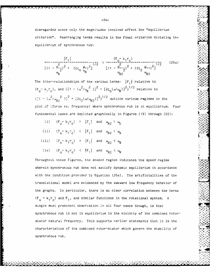
disregarded since only the magnitudes involved affect the "equilibrium
criterion". Rearranging terms results in the final criterion dictating the
equilibrium of synchronous rub:
FJI (Fo- k )--------------- rc--------------- (26a) %.2''"
[ 2 !9 ) 2 1/2 [(I 2 1/2 236, 1[(I - -- ) + (2 0 1 (N- --- ) + (2 2[ ' '--
ON t 'N 2 'N2
The inter-relationships of the various terms: IFIl relative to
(F0 - k r), and {[D - (w2 /,N 2 )]2 + [2(w/)] 2 1/2 relative to
- 2 2 2 2112{ - (W/ )] + [2,( 1N2 )] outline various regimes in the
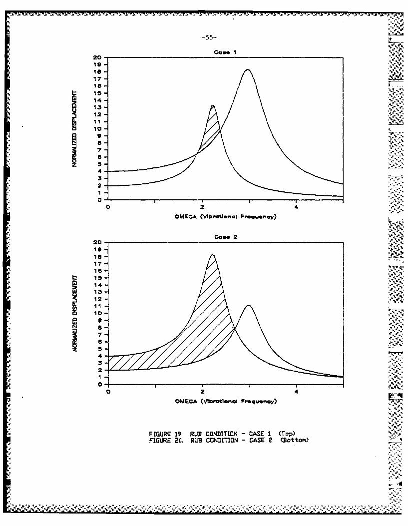
plot of (force vs. frequency) where synchronous rub is in equilibrium. Four
fundamental cases are depicted graphically in Figures (19) through (22):
(i) (F0- k rc) > IF and >
(ii) (F 0- k 1 rc) < IF, I and wN2 >N
(iii) (F0 k r) > IF1 and <N W
-' 1 0 1 N 2 N -.,
(iv) (F0- k1 rc ) < IF11 and wN2 < wN
Throughout tnese figures, the shaded region indicates the speed regime
wherein synchronous rub does not satisfy dynamic equilibrium in accordance
with the condition provided by Equation (26a). The artificialities of the
translational model are evidenced by the awkward low frequency behavior of
the graphs. In particular, there is no clear correlation between the terms
(F - k r ) and F I , and similar functions in the rotational system. Ao 1 c 1
single most prominent observation in all four cases though, is that .. S- -..
synchronous rub is not in equilibrium in the vicinity of the combined rotor-
stator natural frequency. This supports earlier statements that it is the
characteristics of the combined rotor-stator which govern the stability of
synchronous rub.
*.. *. **

-53-
Combining Equations (22), (23) and (24), this criterion becomes:
2IF 1 1[(k 2M + JiDc < (Fo - k r )k /(k + k2 ) (25)
I[(k& 2 + JwD2]1 < (F0- k r )k /(k + k (26)IL2 2 ~ 2 0 i1c 2 1 2
Substituting for the variable A using Equation (24), this condition becomes:
F 1 [(k1 - W 2M ) + jwDI ] k2
IF- 1 2 -< (Fo- -lrc-- - - -1 1 + k2 ) - i+ M2 )] + jw(DI+ D2 )
It is convenient to employ the following definitions when referring to the
rotor, stator and combined rotor-stator:
= [(< I k2)/(ml+ m2) 1/2"
"wN1 ( 1 2M1 12(k /m )112
'N2 (k /m2)1/2
221
o= (DI+ D2)/2[(k1+ k2 )(ml+ m2 )]I/2
1/2= D1/201 m1 I%%
112= D /2[klm2 2 2
The condition that "full annular synchronous rub" be a solution to system
motion now becomes:
2[(1 + j(2C222
k 2 wN2 WN2 k2IFk1 + k2 2 < (F 0) c k1+ k2
[(1 - --- =) +j(2 9-)] 1V22 ON
This inequality may be further simplified by eliminating common factors and
by writing the two complex dimensionless impedances in terms of their 14
magnitude and phase. The phase relationships which evolve may be
,'" f-4-
: pi:
A 4 . % . . - -- . . .S
-55-_
Case I20- _". ,
16 - .** .
17-
15! -
'S%.
14-3. 13 - -.- "
1 -
a S
7-
4 -3 -2
0
0 2 4
OMEGA (Vbrational Frequency)
Case 220-19-
17-16-
J 14 - ",'% -
122§5 115 10-
z 5
4-- 3-
2-.11
O2 4
OMEGA (Vibrational Frequency)/i! 'S<
FIGURE 19 RUB CONDITIDN - CASE I (Top)FIGLRE 20. RUB CONDITION - CASE 2 CGottom)
J %'
, S*
', ', '2# , 'j -.,,.% -,.%_.. ,_,,a'.P,',,..-.- -. - -,_- - .- , .. ,,. , ; .. - ...-.-.-.-.- - . .- ... -,. .. . .. .... , , .- - -_.

-56-
Cae 3 . ,
20-19 -18 - -,,
17-115-
14-
10m10 -
7- '"J
4 -3-2-
010 2
OMEGA (VIbratlonal Frequency)
Come 420-19-
18-
1415-
I .3
12
10
FIUR .1 RUBCODIIO,-CAE,:+ori-R EsRU ONITO -CSE4.-ttM
z S4'.UEP.RgCND[~N-CS Tp :.,.
3 U£L L C3IiID B'-~
2...,1e o
0- '%
• '% % %" " '.%,O. 1% " % " % " o" 2% " % ." l"" 13." ,% " " -% " 4% " .% " ." " .".% % " o ."

-57-
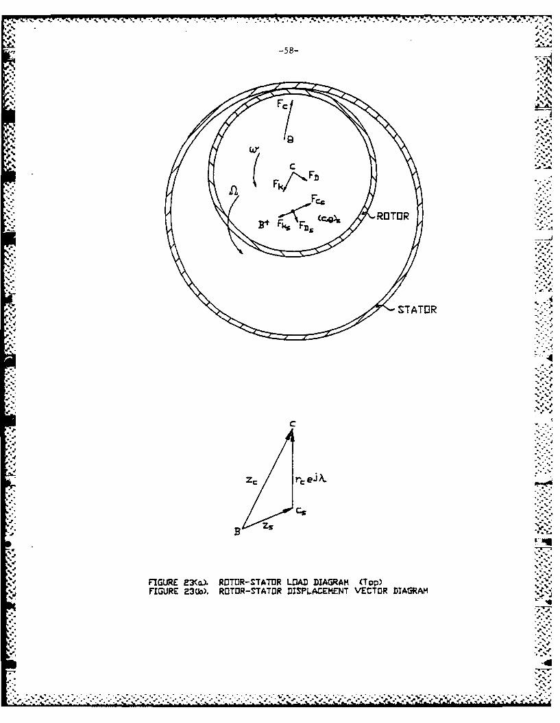
The more exact analysis of the rotor-stator dynamics requires the
assignment of finite mass, radial stiffness and damping characteristics to
the stator in Figure 2. As earlier stated, these characteristics are
assumed axisymmetric. The reference position for both the rotor and stator
displacements remains the imaginary bearing axis, B, which marks the rest
position for the rotor and stator. Figure 23 depicts the rotor in contact
with the stator; with the free body diagrams for each element provided in
Figures 24(a) and (b). The equations of motion for the rotor and stator are
developed according to the balance of forces in the free body diagrams. The
forces acting on the rotor are identical in nature to the forces present in
the rigid stator case. The balance of forces for the rotor is written:
-K z -D r -R(t) = Mr (z g) (27)
.r c rc r
The reaction force which acts at the rotor-stator interface though, is now a
variable which depends on both the rotor's and stator's dynamic -4
characteristics. Since the stator is non-rigid, the reaction force drives
the stator out of line with the bearing center-rotor center axis. The0 r
resultant phase relationship between the rotor displacement and the rub
location may be described by the angle X, which is a function of the rotor
displacement, stator displacement and reaction force lines of action.
Tne reaction force may thus be broken down into its normal and tangential
(friction) components with a periodic time dependence characterized by the
synchronous speed, w, and the phase angle X: -'.7-..
R(t) (N + jpN)ej(Wt + X)
or . ,~ ~~ 2112 eJ(Wt + X + '"--R(t) =N(O + e.,I>
-1-'a-where i tan -I
..--4
-.. ,..~J...-- .-. ,-'.-. . . . . .
-58-
:r< (." ROTOR+ F,
STATOR
c4
QW ' b'r.e J%. .
cs
'.-
a.R.nR.,.
FIGUIRE 23(T ROTOR-STAT-R LOAD DIAGRAM (Top)FIGURE 23(b). ROTOR-STATOR DISPLACEMENT VECTOR DIAGRAM
a.--
-• "- '.
4
~ ~ ~.. .~..d.; i

-59-
"..'1
*F r
Fk.°
+'F4 v 4 " .
Tn -. '.."
4. -. -,
STTU
N c *. VN
.l4 ' " -
T rlR.4.,..
FIGURE 24. RDTR AND STATOR FREE BDDY DIAGRAMS .. ,.
,.,
.4'.'4 1
"4
4
,', ," % % % ,
, ,-,/
-60-
Additionally, the displacement of the rotor's center of gravity may be
expressed:
Zg = IZg lejwt + 6eJ(ut+B)
e is the phase angle which accounts for the lag between the rotor center
and its forcing function. This forcing function now comprises both the
centrifugal force due to unbalance, F , and the reaction force, R(t). The
resulting expression for 0 is thus a function of three phase angles: 4,
the phase angle due to rotor damping; p, the phase angle describing the
line of action of the reaction force at the rub location; and X, the phase
difference between the rub location and the rotor center's displacement:
= a~1 w N1~ 2 1/2 2 2 1/2o = tan-l[Dr+ N(+I sin(+X)]/[(Kr- M + N(1+ 2 )/cos(4+X)]
Making these substitutions, the force balance equation for the rotor may
now be written:
2- D2 12 j(wtA) = M --- ( eJ(wt + )) (
-Krzc r c r dt2 c + (28)dt
Equation (28) may be solved for the displacement of the rotor center:
2 "(Wt+G) 2 1/2 jwt+x+£p)W M6e - N(1+V ) e
z ----- -----------------c r-2
r r rzc = [(Kr- Mr) +(JuDr)] .. (
Breaking the rotor's impedance down to its magnitude and phase yields:
W2M 6 ej(wt+) _ N(p2 1/2 eJ(Wt X+*)
r --- --------------------- e ( )c [(K M2 211/2
[ r Wr +
Dividing through by the term r e and substituting non-dimensional
variables, the rotor displacement may be finally written:
z 2 jO 2 1/2 j(lp+A)Zc _e - - n(l+L8 e ) - e e (29a)
r ej t [(1-82)2, ) 2
c
d % %

K .- 7 T- . - - -. - - - - - - - .
-61-
Whereas the centrifugal force due to unbalance drives the rotor's.
motion, it is the synchronous rub force (i.e., the reaction force, R(t))
which acts as the input driving force for the stator's motion. The forces
which respond to this driving force are the stator's inertial, elastic and
damping responses. The force balance for the stator is derived from the
free body diagram:
-Ksz - Dz- R(t) = z (30)
By assuming a synchronous whirl response by the stator, z= zI ej(wt'.)-4s
and solving for zs, the stator's equation of motion is determined:
~(t).' .,
- [(K - 2 M ) + (j D s
Reducing the stator's receptance to a magnitude and phase, T, and
substituting for the reaction force, the stator's equation of motion %
becomes:
N(JI i 2 )et2 j ( wt +A) -3..
s (Ks- M2 + (wD)21/2[(s 2s s .
1 wDwhere T = tan 2-------2Ms
K - w Ms
This equation may be expressed in non-dimensional terms by utilizing
the following definitions:
d. at.v,
w. K5 /M
w~~s ss
",?. -. :
, D .[2VK M75 S s
%". -

-62-
Now dividing through by the term r e and factoring out the ratio (K /Kc r s
the non-dimensional relation for the stator's displacement becomes:
Kr 2 1/2 j( 4+X-T) %S (Fr )n(1+ 2) e
jWt- 22 2]1/2 (31)r ej [(1- + (2 a"6 )c s s
Two variables of interest in this analysis are the rotor's displacement
and the reaction force at the rotor-stator interface. To determine the
rotor's displacement Zc, Equations (27) and (30) are utilized. The reaction
pforce acting upon the stator is equal in magnitude but opposite in direction
to that acting upon the rotor, so Equations (27) and (30) may be combined
with the force term R(t) eliminated:
4 .
-K z -K z -D z -D z M z + M z (32)r c ss r c ss rg ss
Figure 23(b) provides the vector triangle relating the stator displacement,
rotor displacement and radial clearance. The kinematic condition which
arises from the geometry presented here is given by:
0, j(Wt+A)-Z = r e
V The implication here is twofold:
(i) The magnitude of the rotor displacement relative to the stator
displacement equals the radial clearance between the two elements.
(ii) The point of contact between the two elements must be in line with
the centers of the displaced rotor and stator.
Applying this kinematic relationship and the previously derived condition,
4 6ej(wt+4)z . z + 6e results in the following equation of motion for theg c
rotor:
K d2 j(wt+") K (Wt+)
(Mr+ Ms)zc + (Dr Ds)c+ (Kr K s )zc Mr dt2 s c e
The synchronous whirl solution is thus given by:
-: :,:.:,:,:

-63-
2 j jA jut --[ M 6e + K r e le
z----------------------_----------------------------------c2 (33[(Kr+ K s) - W (Mr+ Ms)] + j[w(Dr+ Ds)]
The time-independent, non-dimensional solution for the rotor displacement
is obtained by dividing each side by the quantity r e and factoring outc
Kr on the right hand side. The resulting expression is:
32 jo K S jX-e +
r _
z K_2 - -- - - - - - - - -f - - - - - - - - - - - - - - - - - e- (3 3a )"- .' ,re J~t K2 2 N]2} 1 12 " " "
reJ {[(I-2) K+N 2 [2C6 + 2C - - ""
K2r wNs 'Ns
-1 W(D + D)where K =tan 2------ ---
(Kr + K) - w (M r + M) s
This equation is further reduced to a single magnitude and phase in the
following:
IK K
-z [E F3 cosp + R -cosx) 2+ (EB sin + K--sinX) 2 11
r j(v-K)-------------------------- f-------------------------------------e (33b)
r ~3t K2rc e7(12) K s 2 N 2 Nr 2 112
Kr "N s wNs
(82 K(Ssin t + -sinX)
-K r
-------- --------
where v : tan K
(Ear 2 ..s +- O
2 K K
r
The reaction force is more difficult to solve than the rotor displace-
ment, but provides much meaningful information regarding the rub motion. A
positive reaction force indicates full annular synchronous rub is in
equilibrium. Conversely, a negative reaction force indicates a no-rub
action, while an imaginary reaction force indicates full annular synchronous
rub is not in equilibrium (i.e., not a solution to the rub equation). In
Ks . .,2 1/

-64- -
order to solve for the reaction force as a function of the rotor speed, the
kinematic condition relating the rotor and stator motion must once again be ,.'
applied:
zc zs ejx
=e
re jWtc
The rotor's displacement relative to the stator is derived from Equations
(29a) and (31):
Kr -J"2 .2 ( - ) (-_ e -
z -z C e-iA KCZc Zs 2 e 112 j s -.-,.• X"")
c-- -- 1 - n(1+1 2 ) e/2 )jt 1/2 1/2 112
r e R R Rc r r s
where R = [(1-8 )2 + (2c,) 2 ]r
and R = [(I-Bs22 + (2C Is2
) ]:.:.
Applying the above kinematic condition, this equation may be written:
Kr )eJiIP-T)
2 j(e- ) K-)F-2e 1- n(l + /2 eJ(--) K e - jx
1I/2 1 I/2 1/2 ]e'eR R R
r r s
Solving for the phasor e yields:
x= 1 /2 2ej(-)L e R c e
K112 2 1/2 12 r 1/2
[(R R) + n(1+2) R cos(p-) + (-r)R r cosOP-)s
2 1/2 1/2 1/2jn(1+p R)[s sin(p-) + (-)R sin -T)j5 K r
S
By defining
-4t
S9 . * 9 4. 9.9, %...
9- 4- -. . . . .. . . . . . . .,.

* --' -. ~ . .- --
-65- _
2 1 1/ 2 Kr)R 1/2n(1+p 2) R I sin(,_¢) + (j ) ( _T)]....
o = tan R K R s-K r
1/2, 2 1/2 1/2 K 1/2(RRs)I+ n(1+p ) [R cos(P-Q) + (-r)R cos(-t)] -, %r "s 3 K r
then the relationship becomes:
eXj = /2 e -- )
1/2 12 1/2 1/2 Kr 1/2 2({(R R ) ~~ ) R cos(ip-4) (--)R cos( p-T)If +
rs 3s K rs
2 1/2 1/2 r 1/2 2 1/2+in(l+i )/[R sin( -) + (--)R sin(,-T)] ) (34)s K r
5
Tnerefore, tne phase angle may be defined in terms of known variables:
wiln the magnitude of Equation (32) being equal to unity. The square of
the magnitude may also be equated to unity, yielding:
R s(2)2( {(RR) 1/2+ n(1+2)/2 [R 1/2 e s ( - ) + K C)R T/2 cos(,-T)]2 +s r s LS cr
K2 1/2 1/2 r 1/2 2+ {n(1+p2) ) [R sin(p-p) + (--)R 1"sin(p-c)]} )- (34a)
K r
Equation (34a) is resolved into a quadratic equation in the variable n in
the following expression:
K 12 2K"'2 2 1/2 r R r Rn (+i) [2(-----cos(T-4) + (- ~
K R K R5 5 S S
2 4112 K Rr (Rr
+ 2n R r cos(W- + o() 1 cos(() -T)] + ,2-'...0
r/2 K R (/2 -(1s4) .
Solving this equation for the tormal force, n, yields the lengthy
expression:
-. ~ ~ ~ ~ , -- T ... --. 77-
-66-
K R(-[Rr os/ s( -t) ] -' 'r K 1
Ks R
K R
1/2 KR± {R cosoip-p) (E- o(PToK R 112-'
1/2 2
[1+2-- -C os(T- + (-E) -][R e /2K R1 1 K R rSK s S
11K 2K R K R
[(+u 2 1 [/1+2 c r r cos( -) (-E) -e]}112K R1 1 K Rss s s
An alternative expression is derived by applying the following
relationships:
2
I/ o ( o .RE } (5)" "
2 1/2 1/2
(1+u2 I/2(1+2 ) Rr ..K~~~ r / --
2[(1B )+ 2 a
S SS S ' '''
cos(IP - ) --------------
(1+ 21/2 1 /2
2 1/2 1 2R
r R
Making these substitutions:
-..
KR+
2 r R 2n =([ -6+2 Bw) + K E -RE1-6B + 2C S 6 S5 5
os(2 -2 ) K R 2 2
s ss
(I+B2)2 )_B
2s 2 )2 2%*
)+(2 )(2 6 ) K R[1 s2 -- -( ) E]( 1 )[R I/2R 1/2
K R K R r
r s
2 2 22 Kr (1-6 )(1-B ) + (2 8)(2 S 8 ) Kr R
- [ - C- (-) - (36)1 K R -' R
s
.;:I : K (-j2(l-s2)(2>)(2s: s K 2 R ". - K - J
-67-
It should be noted that the expression above reduces to the earlier
derived result for rub against a rigid stator (Equation 11)) by employing
the corresponding conditions:
K =, therefore K /K = 0
s r s
C 0R 1.0
The impact of releasing restrictions on the stator's dynamic behavior
is particularly complex due to the numerous variables involved. By
comparing Equations (11) and (35) though, qualitative conclusions may be
drawn. There are three dynamic 'elements' significant to this system: the
rotor, the stator and the combined rotor-stator. The character of the s.,
response of each element is dependent on the speed of excitation and the
element's natural frequency. By considering the magnitude of a generic
element's mechanical impedance, [(K W M) + (0, then it is apparent
that at low excitation frequencies, the response is as a stiff spring,
characterized by the value of K. At high frequencies, the response is as a
massive element; characterized by the value of M. The response is a maximum
in the vicinity of the natural frequency, VK7IM, (specifically at
= 2 2 1/2w [wN2-D /2M] ) These simple principles may be applied to help explain
the dynamics of the rotor-stator system.
Given the rotor's and stator's characteristic mass and stiffness;
the composite element's natural frequen /, wN, occurs between and w *
w~ Ns
- ",~ %
r"-

....... ....... V%. TI K.).M T *jT Zw R.IhC ~ ~ ~ . 4. 4. '.4*'*~ ~ ~~ '.4.q.
-68-
..- _
/+ Kr s .5M+M .4e'-
r s
Three simple relationships thus exist between the rotor and stator:
(i) the stator's natural frequency is greater than the rotor's natural
frequency
(ii) the stator's natural frequency is less than the rotor's natural
frequency
(iii) the stator's natural frequency is of the order of the rotor's
natural frequency
Each of these relationships may be satisfied by several conditions relating
the elements' mass and stiffness. For example, 'Ns > wNr is unconditionally
true when K > K and M = M or when K = K and M < M . It is condi-s r - s r s r- s r
tionally true when K > K and M > M or when K < K and M < M . It is• , ~s r- s r s r- s r
.4 evident that a large number of cases may be analyzed based on the relative
masses and stiffnesses alone. This is exacerbated when variations in
unbalance, friction and damping are investigated.
If us is sufficiently greater than wNr' then when rub first initiates,
the stator response resembles the infinitely stiff case; with the resulting
reaction force depending directly on K . In general, since it is the
stator's stiffness which keeps it pressed against the precessing rotor at
*J speeds below wN' then continuous synchronous rub becomes a less stable mode
of motion as K decreases. As rotor speed approaches w., the rotor-stator5
.4 system becomes very compliant and continuous synchronous rub will cease
(i.e., the radical term in Equation (36) becomes negative). As the rotor
speed further increases and reaches wNs' the stator alone is extremely:s .
*4b

. ..-. .. .* ' , .
-69-
compliant. Since a small push by the rotor thus brings a disproportionately
large response by the stator, then continuous contact may rapidly diminish.
(This is evident in Equation (36) since the value of R tends toward zero as _A
B approaches 1.0 and the negative term within the radical, .2
-(K r/K ) (R /Rs ), becomes dominant). Throughout this speed regime, the"'
rotor's motion (if unperturbed) is identical to that of the free rotor. At
yet higher speeds, the stator's mass dominates the character of its
response. Using limit analysis, the stator'-- behavior once again approaches
the rigid response at very high speeds (B >> B). The criterion for
stability of synchronous rub at very high speeds is identical to that for an
infinitely stiff stator; i.e.,
if >2 1/2
then synchronous rub is stable for B >> a5
At this speed though, the rotor must be perturbed to initiate the rub.
If W and wNr are equal, then the stator's response resembles the
rotor's response for any particular excitation frequency. Therefore, the Oe
speed at which the combined rotor-stator is most compliant coincides with
the speed at which the free-rotor's runout is greatest. This similarity in
response tends to nullify the stator's non-rigid character if (K /K ) andr s
(M /M ) are greater than 1.0. As K and M are increased, the responser s 5 -
rapidly approaches the rigid stator case. When the stator's dynamic
characteristics equal the rotor's, then the speed regime in which continuous
synchronous rub is a solution to rotor motion is identical to the rigid *A
stator case and the reaction force is exactly half that which would result
if the stator were rigid. As the stator becomes less stiff and less
massive, synchronous rub becomes less stable. In the limit, for low values
.-*
.. - .¢ . '. . ' - . . ' °- . - - - - . . . . , - . ,- e f . - . . . . . . . . - . . . .. " '
-70-
of (K /K the system is unable to sustain a continuous rub with thes r
precessing rotor.
If the stator's natural frequency is measurably less than the rotor's,
then the speed regime in which the stator is most compliant occurs prior to
the initiation of rub. When the rotor first gains contact, the stator's
impedance and that of the combined rotor-stator are increasing with the
square of the speed. The response of the system rapidly approaches that of
the rigid stator case as M increases and thus either w decreases or, for
a constant wNs K increases. If in fact a low value of w is due to lowN's Nsvalues of both Ks and Ms , then wN may be approximated by wNr and the rub ..
response is as described previously for N = UNr"
The impact of the stator's damping characteristics are straightforward.
Independent of the natural frequencies, stiffnesses or masses of the rotor
and stator; any increase in the stator's damping coefficient tends to
diminish the equilibrium of synchronous rub. Assuming light damping for '4
both rotor and stator, variations in stator damping has little effect on the
magnitude of the reaction force during rub.
In summary, if the stator's natural frequency is greater than the
rotor's natural frequency, then synchronous rub is not in equilibrium
throughout a speed regime which encompasses the stator's and the combined
rotor-stator's natural frequencies (wNs and UN respectively). This speed
regime widens for a given value of wN as the stator stiffness, Ks, and
stator mass, M , are decreased. Similarly, the reaction force experienced
during continuous rub for a given value of wNs decreases as Ks and Ms are
decreased. As the stator's natural frequency is reduced towards the rotor's 14
natural frequency, this particular speed regime where synchronous rub is not
viable diminishes accordingly. When wNs = UNr' the stability of synchronous
r 44

-71-
rub resembles that of the rotor against a rigid stator; being more stable if
(K /K ) (and thus (M /M )) is less than unity and vice versa. As may ber s r s
expected, the reaction force in this case increases as K and M increase.S S
As the values of wN and are reduced below the synchronous rub system
response becomes as stable as if the rotor were rubbing against a rigid
stator. This is true since the stator's impedance rapidly increases with
the square of the excitation frequency. Regarding stator damping, any
increase in the damping coefficienct, D reduces the speed regime in which
synchronous rub may occur. In general, the stator's finite mass, stiffness
and damping characteristics serve to abate the negative characteristics of ".. *, .,
rotor rub. In no case do these characteristics intensify the reaction
forces between the two elements (when compared with rub against a rigid 1 4
stator), but rather they tend to reduce the reaction forces, often
sufficient enough to create a dynamic relationship less favorable for full
annular synchronous rub (and too, reverse whirl). L,.
Appendix A presents a numerical investigation of the impact of varying
the parameters discussed in this section. Through the efforts of Professor
Udo Fischer of the University of Magdeburg, Magdeburg, East Germany, a
Fortran program has been developed which clearly demonstrates the time -
dependent response of the rotor and stator in accordance with the equations
of motion developed here. The stability of the synchronous rub precession
in those speed regimes where this mode of rotor motion is in equilibrium is
clearly demonstrated.
.4
...$'- _ '.',%1, ,- . .' .',,%' '''•'", ,.,,•." .." -. ., . k .Gi'.% %,L L,'L, '•' '' ¢' '" ¢' . . . . . ."'" '' "" "" '" ' ..e " . .. " ,"" .... ""J" "" "' '" "' '" "' ' '''" ' '" ;" "'.." • . ,. ... - - -,, * , .,,. - ..

-72-
6. CONCLUSIONS AND RECOMMENDATIONS FOR FUTURE WORK
Mechanical vibrations in rotating machinery result from any mass
unbalance present in the rotating element. Should rotor rub occur as a .:\
result of these vibrations, the integrity of the system may be significantly
impaired. Two direct solutions to this problem are immediately apparent: k
(i) Reduce the mass unbalance which drives the vibrations in the -
system, or
(ii) Increase the radial clearance between the rotating element and the .
stationary element. .
Both of these solutions are costly, either through the precision required in
the manufacturing phase or efficiency lost throughout the operational life ,.
of the system.
The dynamics of rotor rub are quite complex, but in general a system° %
may be resolved to one of four behavioral types dependent on the system's
parameters:
l. ..
(i) Synchronous precession without rub
(ii) Partial rotor rub
(iii) Full annular rotor rub
(iv) Reverse whirl
%Most rotating machinery are designed for the no-rub condition. Analyti-
cally, rub may be anticipated if the ratio of the mass eccentricity-to-the- .,:
- .. . . .
Ad___ _ _ ,
: ,,.
-73-
* radial clearance exceeds twice the damping ratio for the system. Should rub
occur, the equilibrium of full annular rub is then dependent on both the ,
rotor's and stator's dynamic characteristics, the system's unbalance, the
radial clearance and friction experienced between the two contacting
surfaces, and the rotor's speed.
Initial analysis was conducted with the assumption that the system's
stator is infinitely rigid. Dependent upon the system's damping ratio, -,,
displacement-to-clearance ratio and frictional coefficient; the rotor's
response as a function of speed can then be characterized according to one
of the following: ..-
-.. .
(i) Limited synchronous rub: Synchronous rub is in equilibrium up to a
"critical speed" (unique to each system) above which equilibrium is never
regained.
(ii) Synchronous rub - limited discontinuity: Similar to the limited
rub case, equilibrium is lost at some critical speed, but is then regained -V
at a higher speed.
(iii) Continuous synchronous rub: As the description implies, this type
system is able to find an equilibrium position for all rotor speeds.
Speed regimes where full annular rub is either not in equilibrium or
not stable may fall into a partial rub (if this mode is in stable equili-
brium at this rotor speed) or jump down to a synchronous whirl without rub.
An alternative mode of rotor motion which may be stable under these
conditions is a reverse whirl driven by the counter-torque produced by the
frictional forces acting on the rotor. Some disturbance is necessary to
perturb the system into the reverse whirl, but such may occur through a
..EZ:-
-74-
transient partial rub motion following the deterioration of full annular
rub.
Expanding the analysis to investigate the impact of the stator being
non-rigid results in extremely detailed equations describing the motion of
the system and the forces at work between the rotating and stationary '
element. In contrast to the rigid-stator system, the stator now joins with
the rotor in responding to the unbalance driving the vibrations. In
general, equilibrium of the full annular rub diminishes in the vicinity of
the combined rotor-stator natural frequency (which previously was infinite).
Additionally, the amplitude of the motion varies greatly now that the stator
is not absolutely constraining. If the stator natural frequency is greater
than the rotor natural frequency, then the recurrence of rub at speeds above
this requires some perturbation to initiate contact. In general, the finite
dynamic characteristics assigned to the stator which make it non-rigid
diminish the reaction forces experienced by the rotor and stator (as
compared to the rigid stator case) and in fact may create a dynamic
relationship less favorable for fuli annular synchronous rub.
Much work remains to be accomplished in the study of rotor rub.
Experimental investigation of the results presented here would prove
particularly meaningful in validating the results and justifying the
assumptions made. An analytical investigation of the equilibrium conditions
for partial rotor rub would be very complementary to this study on the full
annular rub problem. Of particular significance would be work which
contributes to the analytical determination of the stability of full annular". -
rub, partial rub and reverse whirl for a rotational system as a function of
the excitation frequency.
.° °
.•.'
.-.,
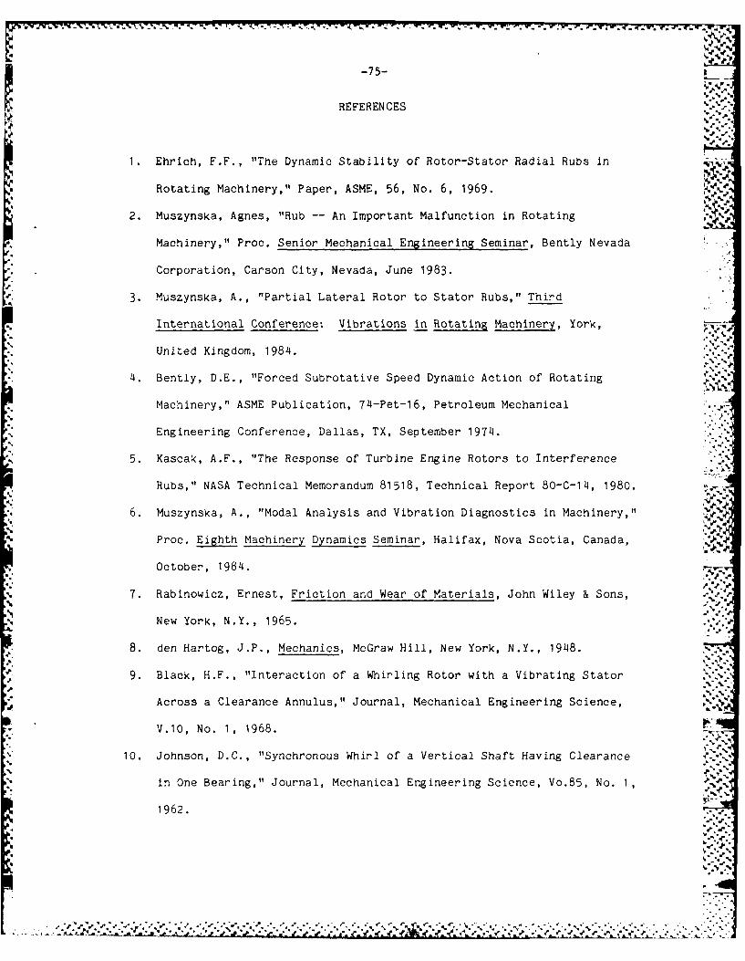
-75-
REFERENCES
1. Ehrich, F.F., "The Dynamic Stability of Rotor-Stator Radial Rubs in
Rotating Machinery," Paper, ASME, 56, No. 6, 1969.
2. Muszynska, Agnes, "Rub -- An Important Malfunction in Rotating
Machinery," Proc. Senior Mechanical Engineering Seminar, Bently Nevada
Corporation, Carson City, Nevada, June 1983.
3. Muszynska, A., "Partial Lateral Rotor to Stator Rubs," Third
International Conference: Vibrations in Rotating Machinery, York,
United Kingdom, 1984. .
4. Bently, D.E., "Forced Subrotative Speed Dynamic Action of Rotating
Machinery," ASME Publication, 74-Pet-16, Petroleum Mechanical
Engineering Conference, Dallas, TX, September 1974.
5. Kascak, A.F., "The Response of Turbine Engine Rotors to Interference
Rubs," NASA Technical Memorandum 81518, Technical Report 80-C-14, 1980.
6. Muszynska, A., "Modal Analysis and Vibration Diagnostics in Machinery,"
Proc. Eighth Machinery Dynamics Seminar, Halifax, Nova Scotia, Canada,
October, 1984.
7. Rabinowicz, Ernest, Friction and Wear of Materials, John Wiley & Sons, .
New York, N.Y., 1965.
8. den Hartog, J.P., Mechanics, McGraw Hill, New York, N.Y., 1948.
9. Black, H.F., "Interaction of a Whirling Rotor with a Vibrating Stator
Across a Clearance Annulus," Journal, Mechanical Engineering Science,
V.10, No. 1, 1968.
10. Johnson, D.C., "Synchronous Whirl of a Vertical Shaft Having Clearance
in One Bearing," Journal, Mechanical Engineering Science, Vo.85, No. 1,
1962.
;,T,..

-76-
11. Billett, R.A., "Shaft Whirl Induced by Dry Friction," Engineer, V.220,
No. 5727, 1965.
12. Childs, D.W., "Fractional-Frequency Rotor Motion Due to Non-symmetric
Clearance Effects," ASME Publication, 81-GT-145, International Gas
Turbine Conference and Products Show, Houston, TX, March 1981.
13. Morris, J., "The Impact of Bearing Clearances on Shaft Stability: A
New Approach to Shaft Balancing," Aircraft Engineering, V.29, December
1957.
14. den Hartog, J.P., Mechanical Vibration, 2nd ed., McGraw Hill, New York,
N.Y., 1940. -
do,
9.7
• -.
'..

-77-
APPENDIX A
It is the intent in this Appendix to investigate the dynamics of
several exemplary rotor-stator systems in accordance with the analysis thus
far conducted for rotor-rub. Unlimited combinations of rotor and stator
dynamic characteristics are possible, but here a limited number are studied
to demonstrate the impact on system behavior of varying key parameters. In
particular, variations in rotor and stator natural frequencies, stiffnesses,
masses and damping characteristics are investigated. Similarly, the effects
of varying the magnitude of the unbalance and friction are studied. The
indicators for system behavior deemed here to convey the most information
are:
(i) Rotor Amplitude vs. Speed
(ii) Normal Force vs. Speed
(iii) Rotor and Stator Displacement History
W
Synchronous rub is presumed in the analysis, and is indicated by stable
rotor displacement solutions (aside from the fundamental free-rotor
solution) in conjunction with a real, positive reaction (or normal) force at -
the rotor-stator interface.
The plot of rotor amplitude (z /rc) vs. frequency ratio (w/uN) is%c c Nr
Cpresented for the two solutions to Equation (29) as well as the free-rotor
solution to Equation (4). The free-rotor solution (depicted by the broken-
line) is the only stable solution below the rub speed, Brub and is again
stable at speeds greater than B' (described in section 3). Both equilibrium
solutions to Equation (29) are presented (depicted by the solid lines - ',
**'*'~d:, ....

-78-
labelled I and 2), but it is only curve 1, that solution initiating at the
rub speed, which provides stable equilibrium. This is somewhat intuitive by
analyzing the geometry of the rotor and stator equilibrium conditions (such
as Figure 23) corresponding to a particular speed of interest. Where the
solution is discontinuous, the recurrence of this stability is not assured.
The normal force is also plotted for the stable solution as a function
of rotor speed. Regions where the normal force is negative indicates rub is
not in action. It is immediately apparent that no solution exists for
synchronous rub in the vicinity of the combined rotor-stator and the stator
natural frequencies. Stability of equilibrium is determinable using a ..
simulation program provided by Professor Udo Fischer which traces both the
rotor's and stator's displacement as a function of time. Several examples - -
of both stable and unstable equilibrium are provided throughout this
appendix. A stable equilibrium is indicated by the constant orbit of both
the rotor and stator. This solution may be artificially perturbed (through
initial conditions to the program), but still returns to the equilibrium
condition. Unstable equilibrium is evidenced by varying amplitude of both
rotor and stator displacement, typically ending in the rotor undergoing a
synchronous whirl without rub while the stator returns to the rest position.
Two primary groupings are analyzed: 'Ns > wNr and wNs < Nr". A total
of 18 cases are presented with their key parameters outlined in Table Al.
Rotor characteristics are indicated by subscript 1 while stator characteris-
tics are indicated by subscript 2. One baseline case for each of the ..,.<..
primary groupings is analyzed, with comments regarding each subsequent case
within the grouping being referenced to the baseline case (unless specifi-
cally stated otherwise).
These cases, as described in the following, clearly demonstrate the
impact of varying the system's parameters as previously discussed:-.. .
.-. jl .oj..., •... ,..- °% -. : .'.._ -- . .• .... .- <.] ..-. ,-. .. - o.- - . .. _-_-.. .- -...- , -- -. -.

-79-
Case 1: This case provides the baseline for the condition w > r As an xM
example of limited synchronous rub, only a limited speed regimes exists
wherein synchronous rub is in equilibrium. -71
Case 2: This case demonstrates the impact of an increase in the mass
unbalance. As an example of synchronous rub-limited mass unbalance. As an
example of synchronous rub-limited discontinuity, synchronous rub is in
equilibrium for all speeds greater than the rub speed, except for a limited
region demarked by the combined rotor-stator and the stator natural frequen-
cies. Additionally, the amplitude of displacement is increased above the
baseline while the reaction force increases severely. -_ .11.-Case 3: A reduction in friction increases the speed regime wherein
synchronous rub is in equilibrium. Concurrent with this is a large increase
in the reaction force.
Case 4: Similar to Case 3, a reduction in stator damping leads to estab-
lishing the equilibrium of synchronous rub over all speeds outside of the
combined rotor-stator and stator natural frequencies. As well, there is an
increase in the reaction force.
Case 5: Reducing the rotor's damping results in a large increase in the
amplitude of displacement (above the baseline) and a slight increase in the
speed region for synchronous rub. No recurrence of rub occurs though above
the stator natural frequency.
Case 6: An increase in excitation and damping on the rotor and stator
demonstrates how the damping reduces the displacement and reaction force at
low speeds (in comparison to Case 2), but has little impact at high speeds
:, ~(W > WNs )."'"
Case 7: Reducing stator rigidity while maintaining the same stator natural 4e
frequency results in a reduced region of synchronous rub and a reduced
reaction force.
, - .%,

-80- __
Case 8: Converse to Case 7, increasing stator rigidity increases the region - ,
of synchronous rub and results in increased reaction forces. ,
Case 9: Increasing stator stiffness and so the stator natural frequency
extends the speed regime for synchronous rub while causing an increase in
the reaction force and a reduction in displacement.
Case 10: Increasing stator stiffness and the excitation demonstrates the
large displacements and severe reaction forces that may develop. Once
again, synchronous rub is re-established above the stator natural frequency.
Case 11: This case represents the baseline for the condition wNs < wNr A
limited synchronous rub occurs with a displacement less than the radial
clearance.
Case 12: Increasing excitation results in a continuous synchronous rub with
significant reaction forces developing at high speeds.
Case 13: Reducing friction also causes a continuous synchronous rub to
occur similar to the previous case.
Case 14: Reducing the stator's damping has only a slight impact on the
reaction force and equilibrium range for synchronous rub at speeds much
greater than the stator natural frequency.
Case 15: Reducing rotor damping results in a continuous synchronous rub
similar to Case 12.
Case 16: Increasing stator rigidity, while maintaining constant natural
frequency reduces the speed regime of synchronous rub in this case while
causing the amplitude to approach the radial clearance.
Case 17: Converse to the previous case reducing stator rigidity for a given
WNs, causes a reduction in amplitude with a slight increase In the speed
regime for synchronous rub.
°-. .-
.o•°- °- °°°- - - + + ° - °- 4 + . , ° ., ° . .. . . . . . . . .... . . .. • °
-81-p--wV
Case 18: Increasing stator mass (and thus reducing N has little effect -- 'Nsj
on the speed regime or reaction force of the synchronous rub, but does drive -
the displacement toward the radial clearance (i.e., the rigid stator
condition).
The stability of the solutions represented by displacement curves 1 and
2 is analyzed for the three rub behavior types: limited synchronous rub
(Cases 1 and 11), synchronous rub-limited discontinuity (Case 2) and
continuous synchronous rub (Case 12). Within these examples, several speeds
are investigated in order to study the stability of each speed regime
wherein synchronous rub is in equilibrium and too the stability of the two
solutions at those speeds. These examples demonstrate the inherent
instability of curve 2 solutions as well as the variability of stability
associated with curve 1 solutions. In particular, curve 1 appears stable
for both the limited rub and continuous rub conditi(ns, but there is a speed
range within the synchronous rub-limited discontinuity equilibrium solutions
wherein stability is lost.
,".. ".h
;-.-- *.-
-.& - , ..... . .L L. . .

-82-
TABLE Al
Case No. K2/KI M2/M1 DI D2
1 4.0 1.0 0.2 0.2 0.3 0.3
2 4.0 1.0 0.2 0.2 0.5 0.3
3 1.0 1.0 0.2 0.2 0.3 0.2
14 4.0 1.0 0.2 0.0 0.3 0.3
5 4.0 1.0 0.0 0.2 0.3 0.3
6 4.0 1.0 0.4 0.4 0.3 0.3 _
7 1.0 0.25 0.2 0.2 0.3 0.3
8 8.0 2.0 0.2 0.2 0.3 0.3
9 16.0 1.0 0.2 0.2 0.3 0.3
10 16.0 1.0 0.2 0.2 0.5 0.3
11 1.0 4.0 0.2 0.2 0.3 0.3
12 1.0 4.0 0.2 0.2 0.5 0.3
13 1.0 4.0 0.2 0.2 0.3 0.2
14 1.0 4.0 0.2 0.0 0.3 0.3 e. %
15 1.0 4.0 0.0 0.2 0.3 0.3-.-
16 2.0 8.0 0.2 0.2 0.3 0.3
17 0.25 1.0 0.2 0.2 0.3 0.3
18 1.0 9.0 0.2 0.2 0.3 0.3
.. . .'. . . ..
,-.-, x .- .'- . .. :

-83-
t4,
* J*Ja
tm4
qt.
I I %
X~-
Is*1Ca (\Ie. .1
w I
-4 1
LL.4
.1* - 11"-- - - -
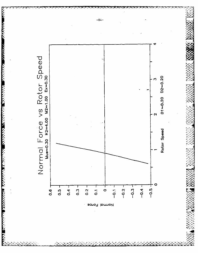
-84-
- '.' .*..
0~
0f~o 0
o00
10
00
o a o 6 - o -
C')n
Q: =O IOU."UON '''
# % *. #0'. .P.0
-'U --0
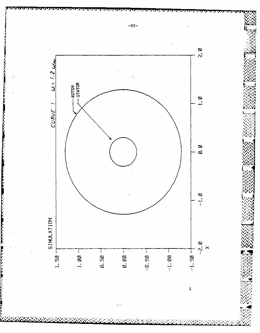
-85-
C 4
Ea I---cEe-
cy-
0::m
cm.
rmA
z .
In) xf fM -..
LO m ** .n m U-)-q -4"6 %

-86-
20I I I c
'p I jLI .
N
6 - -<- I
p~wN NL
'If6 UdW

*.: -7;. . - - , '. W* - - - -'
-87-
1)0 0
~il 6
0 CL A
ii 0
0) C o N
OD-JOJIDU"-
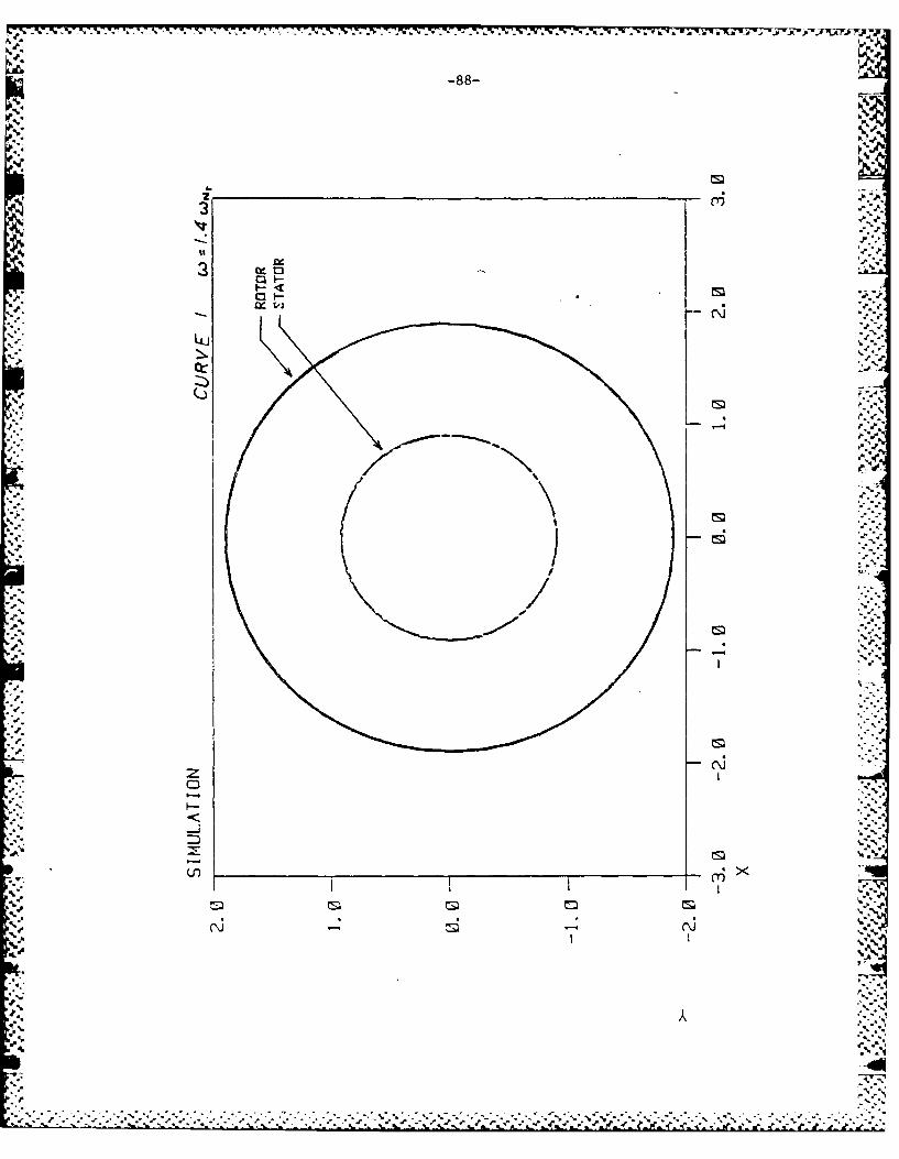
-88-
r'a-
Ix.
33
.. ....... .-
NNN

-89-
N5*2
LLJ D~
te.
-. e If

-90-
4w %
'Is
Lu
IX 0
I-
4L
2cm
If) tf n n%
CD m
Ln Uq

-. -- f-l -- pw -x Y - .
1-91
. 14
is, 3
LOl
(~cm
4 IICI:
. l . . . .
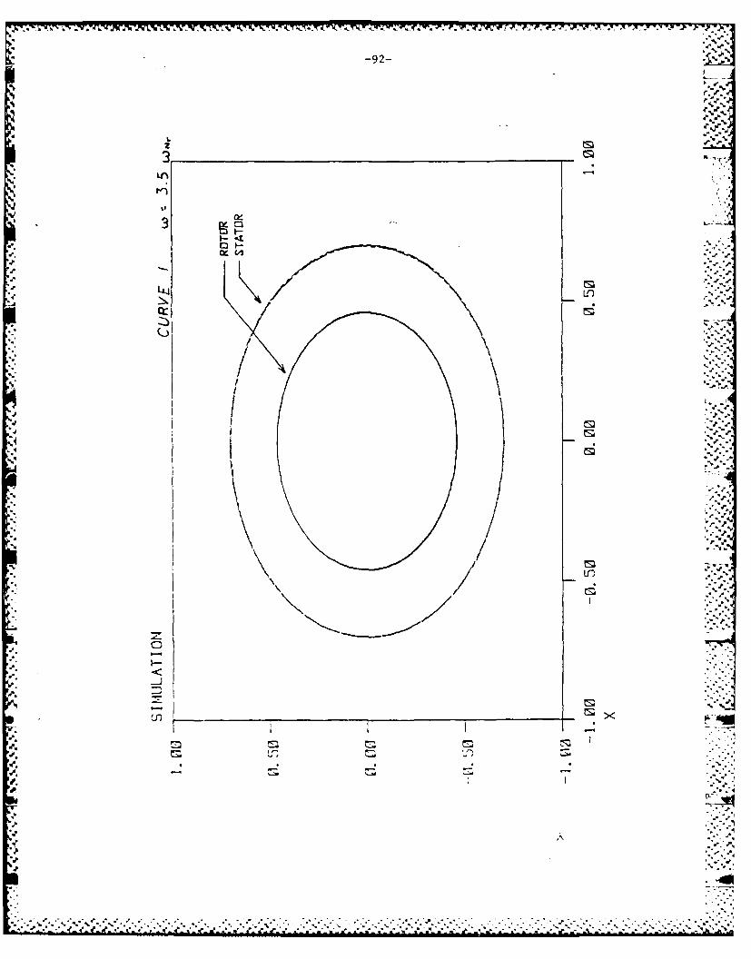
* * S S A. . -- 4. *.5. *1. - -
S ** .~5
- -S-9z-
.5.5r, r
Sq
Sq-~
- L2 5--.
-~ ___________________________________________
LA -
II.5-
S..
.5.
LL.j
-a
(5,
-55-.
'p
4 I I S
.4 IS.
.5
'p
5-5
'.5-.
*5PS
'p.
*5*. I-5'
S.. -
.5 ~1S
4 I*5% 5*-.
4 5
Spa. - - -'
'5
S~.
A5.
.5'.
5,
*.-:*.~-.:%\-%'-.-w.*.~-.:.:-.-*.-~.-.-.. ':'.2~-.*~*-i*- :--K-.2 -.-.-.-.-. '.**.P*~**.-K* K. K .-: *Kf..............................................

-93-
L&JO
Lflx

-94-
I.m
C%4CM
a I I
Ca N
0 W3
I V.(N
C'j NM
x~Y- lH

AD-RI?3 311 D YNAN CS OF FULL NNUL R ROTOR RU BU) N SS C USETTS 2/2
I INST OF TECH CANIRIOGE DEPT OF OCEAN ENGINEERING
UNCLASSIFIEID SJSRKEJU 6F/ 2/1NL
I flf~ffflflllff

L1.0.
III1
111111 1L. L3 6
1-114 - "jIII~ ~ I -
MICROCOPY RESOLUTION TEST CHARTNAI(ONAL BUREAU OF SIANDARDS 1963 A
"-j
"_- .S.: ." _,". -:' ,' -" .'"- '"" " " " ' " ' "'" " " " " -'- - -" '-" .. . "- "- --- "-" " . ...

-95-
00~
ci r) cy
x ii.w - Y
.04
6
0
0 S. 0
zoN A
DzJ04 IDuIJON

-96- M-
I -4
I 02
w/2 .9
wS -
0 1 *.p- **jW
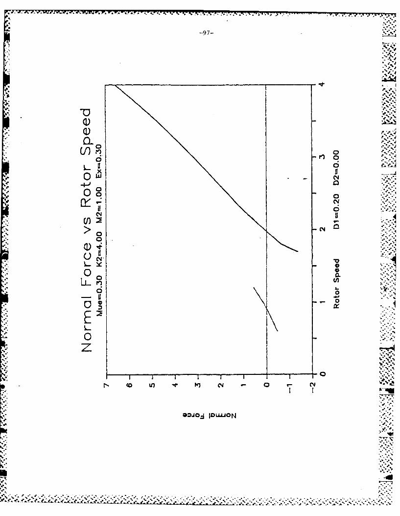
-- 7
Oo
'I 4
a. Q)
0~ CL
* L~J0
0
Nfi' a a
0OJO 1)0 pa

-98-
tm,
MN
Im
* I* I ri.
X N
wN
C-N,
I I ( 02
I j
w N
0N- 1 -. -I
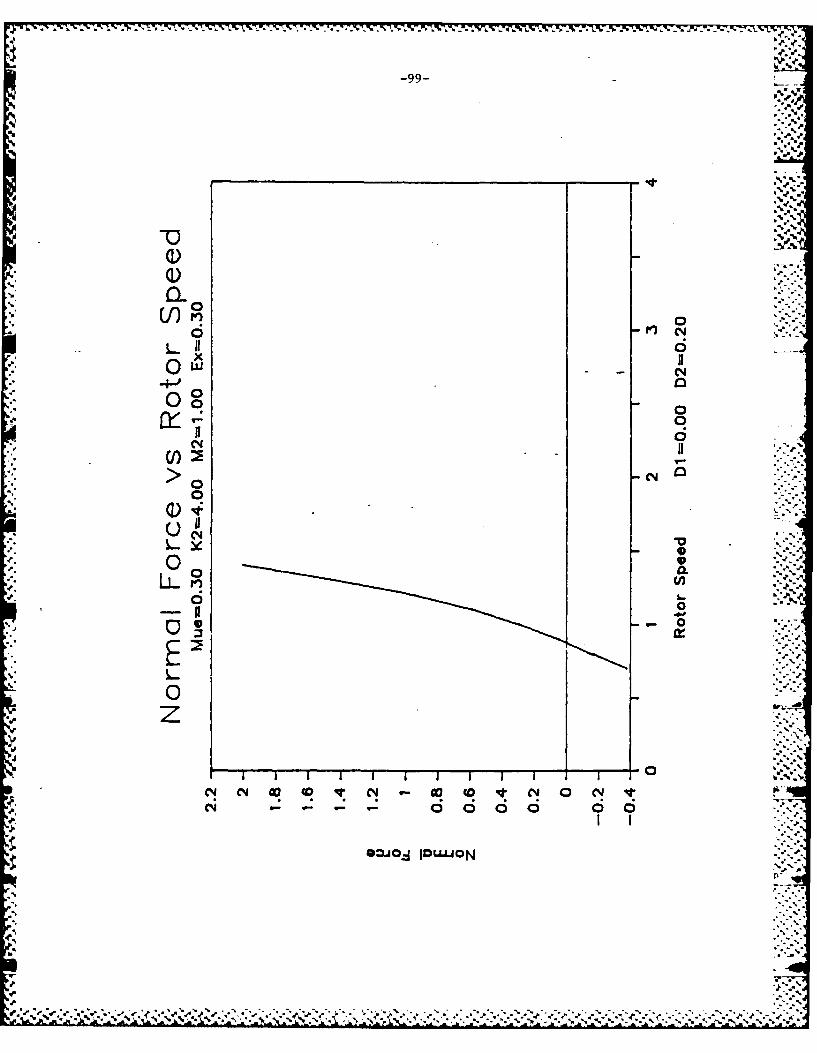
-99-
-4-J.000~0
0
'LL (Aiv
LI1 000 DV0 o ,N0NI
C4 6
GZN OLO
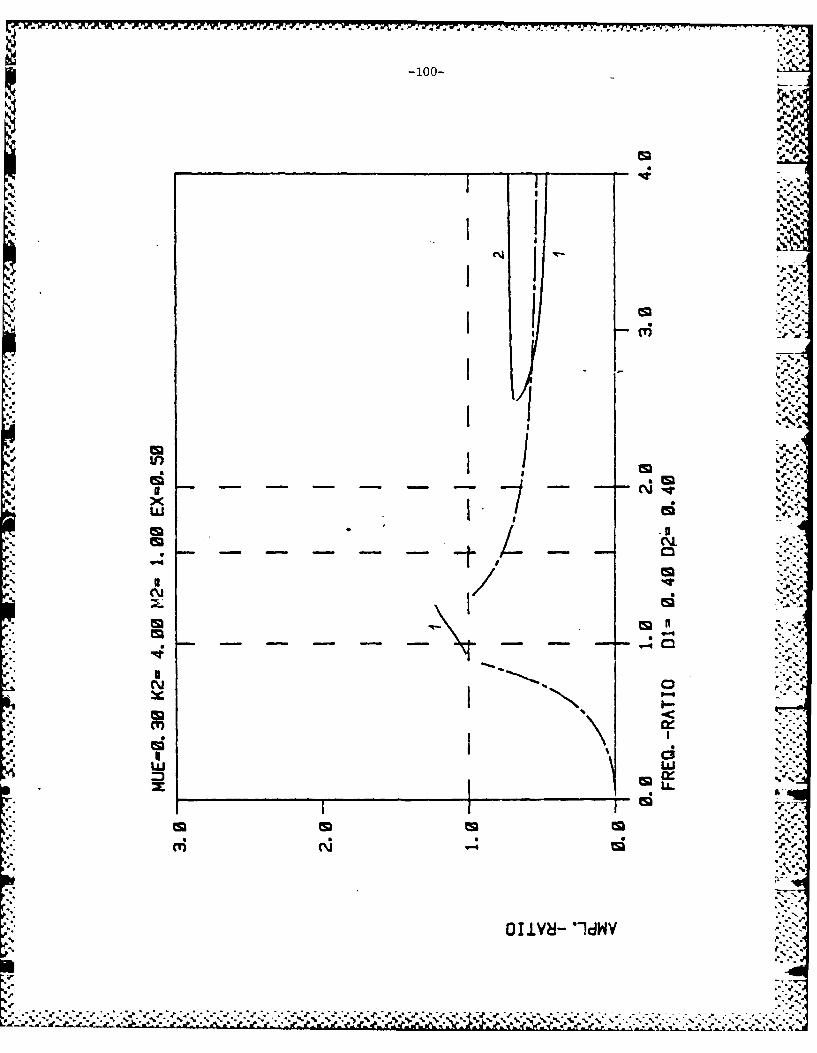
~~~~~~~*~~~~.. 77 7 7~JJ T7-T' '.~~--z - " . .~J~
-100-
cmA
M
I I%
553
Ca <
w I.
OLYN *- IW

-101-
in 0.
cvvci0 6
0 0
Cl I
>0 CL0
00
00JO a."O
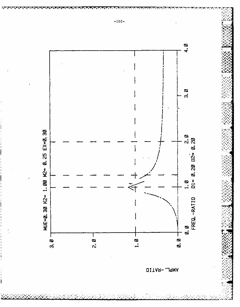
-102-
N -- - - - - -N NMw ILr) .
c~Jcm NGwM
x _________________________________________________
cm '-4
OItm 1H
CM* .. .
CaI

-103-
% %
~L0
x inQw (0
0
Cl a C1 In VI6 6 0
DONO 10B

'X ~ ~ ~ ~ ~ ~ ~ ~ ~ ~ T -7J .~ .J .2 ~ Y ~ 2 ~ . ~ .
-104-
ED a
cm a ~
MNCtzzzzlCa I
C .
-~Y8 -IW

-10 5-
p -- 4
00
000
Q Ce4 c1I
II 0
>0 r,( n M NV C ' J)I000oooo666666666
soUicuAO

-106-
U.1.
N C.
I I I ~. :~-d
IL IL
tm
0 1 (L6-mJdW
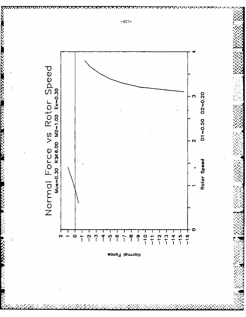
-10 7-
4- .
CI0
LIIC6
-a 0
N=O IIDiO

-108-
LI)
U InNxS
N
N oi
ii ci
W. ZW0 1 V6 LlW

-109-
LLJm
____ ____ ____ ___ ____ ____ __
0 .
C!05--
00
-cv
0
IDU"ON

-:%r .5-7-. " -w -. 7 7 - :
-' -110-
I~ rr--r4' II *~ x
LL)-F
.4 I a .
* I I .cm
m I a
N 0
Im N
tm =
fLL
ED I EDEd1
w 1 L8 idW

-C-
0
J.ii
cqN
0mOH 60"O
c'J Ad

1 - d 1
-J.~KS 1>% J
L hn
33I-
V- < c5- /- CDabe C-1
L'-a
4..1

-113
L~LJ
z-
Ln Lr.

I -114-
ai M
w 1i
a
x a1
0 J C\i
I Itm Ir
x. -
OR0
* -g*'dW

N N; I. -
(A '~
6 'd
'V
4' 0-~66
r). -- 0 )MC-WV tX
QO4J'~uO
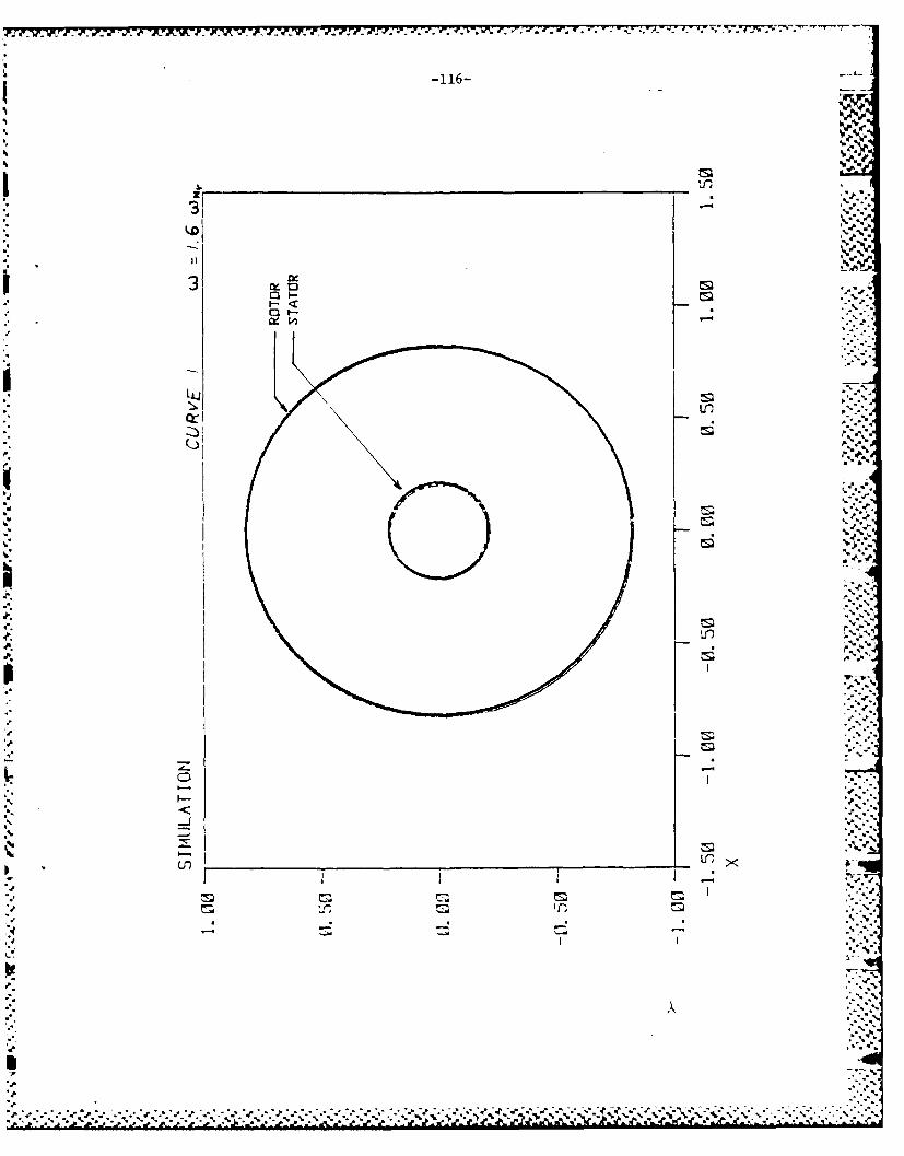
-116- -
I.z
I _ __ __ __ __ __ __ ___ __ __ __ __ _ of
XiccW. 3 s
c
i~
&L
CD ..
.1-. 77V

Ix 0
IIl
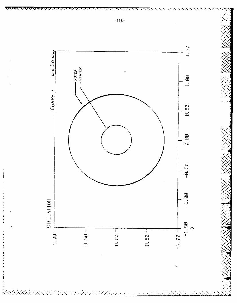
4.~y~JJ.7..W 7 . . 7- - - . 777. ~.
CV- M
QL)
3n x
LL u

3Q,%0
Ltt
3C
01-X
4.q

-120- t.-
1r
I I - ~.r
I 1
I.L.1ED
m ~ 020
- - - - 4 -
OIIV8-"ld-
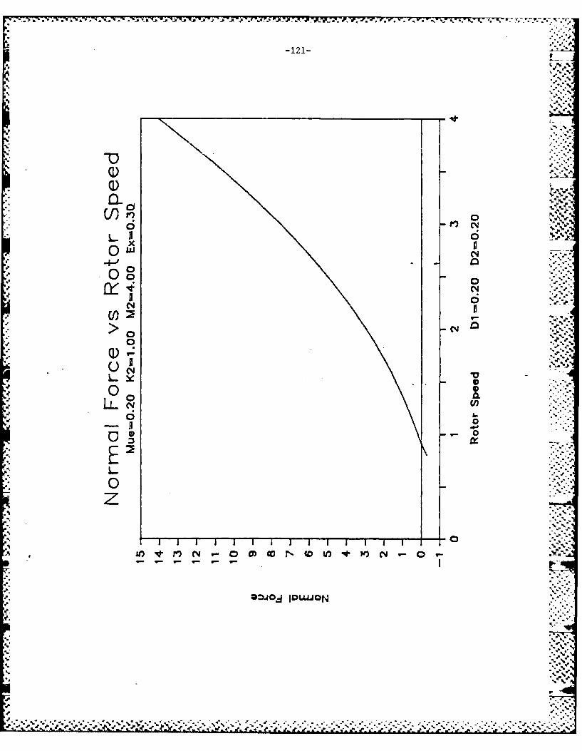
4- 0
-'Y*
-o> CY%
(I)',
C)J
>01) N0 C o t ',P) C
D4-~ 00"

-122-
m
%~
N "
wv
CM,ta NI ~
In Ix
I I.,.,
II -- /Nm
-4 -I.IdW

-123-
P.
". %
-q-
(1)) % U
000
t~~~l)gV 0n 0 ni rLI' 6
-Po*-
I77

-124-
J.4.
Ma III
I 1
w Id
I
S. /S. rI
N 1 0V-0IW

-125-
00
6 cy
6C)
>0
00
V)/
0
0
DoI I - -N

-126- ,
jjtIL m;
Im I i .l*- i
tm N
00N~
N i s;
'.4 * -
-tm-,
C-i C3
xc
ouiV8-ldWY
.5 %5*.~. \%S%* ~ *,.5..* . -. * .~. . .. . . .. -
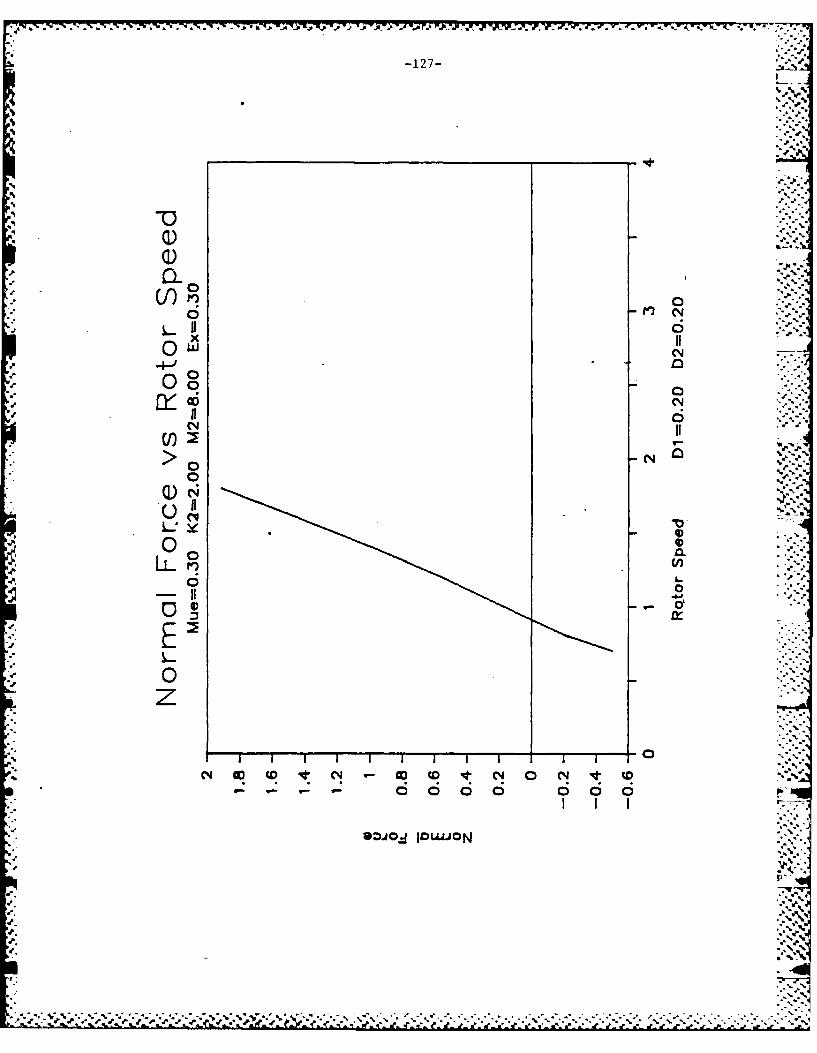
-127-
ic
x 1
'4
IQ)
0 ML,
L61 6 ;c
xZJO II"O

-128-
tm4
p I I
I a)
I P. w-
Ln M P.. *d.
w W,
t 4
- - - - - -d
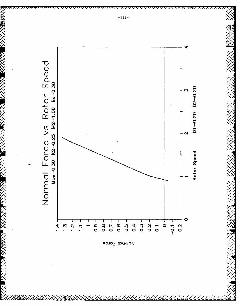
-129-
-4-
I6-Q
4o 00(0
II 6C4i
- 4-0
0000
fn1 CYM CoN Q JV )N
6*t 6 6c ic
OD-JJ 'C."O

-W . 7 . . - - .
-130-1
I EDNYA
Ca-
I pIC
x 0
ts)~
ww
LL. : . ~
m1 E DS5
OI.LV- 1dWV
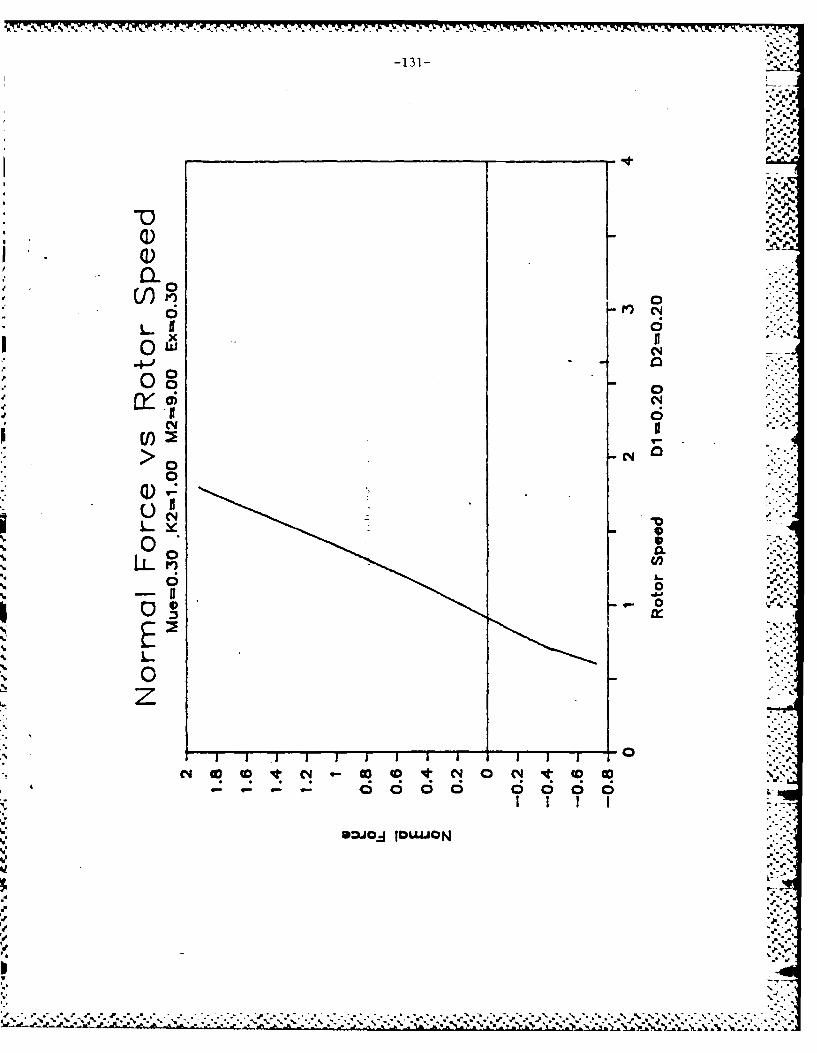
-131-
AA
C-4.
x~
w N*
~0
0 0
C4
0 0
0
6p 6I 66
O=* NO"O

A'
N4 .1'
'I.
-4
A',
.c.
K
1-.-----
4-
A
w I,
a
I.. ~
4/4. .~.