inspection of austenitic welds in iter vacuum vessel …
TRANSCRIPT

829
INSPECTION OF AUSTENITIC WELDS IN ITER VACUUM VESSEL WELDS WITH
ULTRASONIC PHASED ARRAY TECHNOLOGY.
A. García, F.J. Fernández, M.C. Pérez, R. Martínez-Oña, Tecnatom, Spain; G. Pirola,
Ansaldo Nucleare, Italy.
ABSTRACT
The ultrasonic inspection of austenitic welds has always been a great challenge due to the dispersion and
attenuation of the ultrasonic beam in these materials. In the case of the ultrasonic inspection of ITER
Vacuum Vessel welds, the complex geometry of this component adds to these difficulties.
Seven sectors of the ITER vacuum vessel will be manufactured by an Italian Consortium led by
Ansaldo Nucleare and including Mangiarotti and Walter Tosto as manufacturing partners; Tecnatom will
be in charge of performing the ultrasonic qualification.
To detect and characterise defects in these materials, Tecnatom is developing an ultrasonic
inspection technique based on the phased array technology using dual probes. This technique will be
qualified under the supervision of the European Domestic Agency “Fusion for Energy”, responsible for
managing the production of the seven sectors of the vacuum vessel mentioned above.
This paper will show the main tasks achieved in the development and implementation of this
inspection technique, which have been as follows:
• Specification of phased array probes adapted to the component to be inspected (defined by
its geometry and materials) and the type of defects postulated (defined by their type, size, shape and
position). As a support for the definition of the array probes, simulation tools have been used to predict
the shape of the ultrasonic beam.
• Design and manufacture of scanners, specific for the ultrasonic examination of the
components subject to inspection.
• Performance of ultrasonic examinations on test pieces with realistic defects for the
optimisation and tuning of equipment and inspection techniques.
INTRODUCTION
The vacuum vessel is an austenitic steel component that houses the fusion reaction. The plasma particles
revolve inside a toroidal inner chamber with a D-shaped cross-section. Both the design and manufacturing
of the vacuum vessel and the corresponding examinations are in accordance with the requirements of the
2007 edition of the RCC-MR Code.
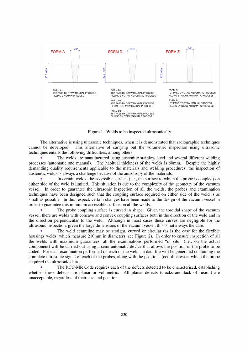
This Code requires that a radiographic examination be performed on all category 1 and 2 welds of
the vacuum vessel. Given the geometric characteristics and the construction sequence of the vacuum
vessel, certain of these welds are accessible only from one surface. These characteristics mean that it is
not possible to perform the volumetric examination of these welds (represented in Figure 1) using
radiographic techniques.
830
60.0
(40.0
)
60.0
(40.0
)
60.0
(40.0
)
FORM A11ST PASS BY GTAW MANUAL PROCESSFILLING BY SMAW PROCESS
10.0°
FORM A
FORM D1
1ST PASS BY GTAW MANUAL PROCESSFILLING BY GTAW AUTOMATIC PROCESS
12.0°
FORM D
FORM D2
1ST PASS BY GTAW MANUAL PROCESSFILLING BY SMAW MANUAL PROCESS
FORM D3
1ST PASS BY GTAW MANUAL PROCESSFILLING BY GTAW MANUAL PROCESS
FORM Z11ST PASS BY GTAW AUTOMATIC PROCESS
FILLING BY GTAW AUTOMATIC PROCESS
FORM Z
FORM Z21ST PASS BY GTAW MANUAL PROCESS
FILLING BY GTAW AUTOMATIC PROCESS
4.0°
Figure 1. Welds to be inspected ultrasonically.
The alternative is using ultrasonic techniques, when it is demonstrated that radiographic techniques
cannot be developed. This alternative of carrying out the volumetric inspection using ultrasonic
techniques entails the following difficulties, among others:
• The welds are manufactured using austenitic stainless steel and several different welding
processes (automatic and manual). The habitual thickness of the welds is 60mm. Despite the highly
demanding quality requirements applicable to the materials and welding procedures, the inspection of
austenitic welds is always a challenge because of the anisotropy of the materials.
• In certain welds, the accessible surface (i.e., the surface to which the probe is coupled) on
either side of the weld is limited. This situation is due to the complexity of the geometry of the vacuum
vessel. In order to guarantee the ultrasonic inspection of all the welds, the probes and examination
techniques have been designed such that the coupling surface required on either side of the weld is as
small as possible. In this respect, certain changes have been made to the design of the vacuum vessel in
order to guarantee this minimum accessible surface on all the welds.
• The probe coupling surface is curved in shape. Given the toroidal shape of the vacuum
vessel, there are welds with concave and convex coupling surfaces both in the direction of the weld and in
the direction perpendicular to the weld. Although in most cases these curves are negligible for the
ultrasonic inspection, given the large dimensions of the vacuum vessel, this is not always the case.
• The weld centreline may be straight, curved or circular (as is the case for the flexible
housings welds, which measure 210mm in diameter) (see Figure 2). In order to ensure inspection of all
the welds with maximum guarantees, all the examinations performed “in situ” (i.e., on the actual
component) will be carried out using a semi-automatic device that allows the position of the probe to be
coded. For each examination performed on each of the welds, a data file will be generated containing the
complete ultrasonic signal of each of the probes, along with the positions (coordinates) at which the probe
acquired the ultrasonic data.
• The RCC-MR Code requires each of the defects detected to be characterised, establishing
whether these defects are planar or volumetric. All planar defects (cracks and lack of fusion) are
unacceptable, regardless of their size and position.

831
Figure 2. Welds of form A with straight and circumferential trajectories.
In view of the difficulties described above, the European Fusion for Energy Agency, which is
responsible for managing the manufacturing of seven sectors of the vacuum vessel, requires the
qualification of the ultrasonic volumetric inspections of welds accessible from a single surface. Tecnatom
is responsible for such qualification.
INSPECTION TECHNIQUES
Taking into account all the ultrasonic examination requirements indicated above, the basic ultrasonic
technique proposed is the pulse-echo technique, using a phased array probe performing the inspection in
the two directions (perpendicular and parallel to the weld) and in the four possible orientations (Y+, Y-,
X+ and X-). This probe is of the dual type (i.e., with the emitting and receiving stages separate) and is
mounted on an angle wedge. The active surface of the probe is made up of two lines of transducers with
up to 28 elements (see Figure 3). The advantage of using a phased array probe is that this type of probes
allows scanning movements to be minimised (this being adequate in view of the small space available on
either side of the weld), and also allows ultrasonic beams with different angles and with both types of
wave (longitudinal and transversal) to be refracted in a single examination.
With dual probes, the maximum sensitivity occurs in the zone in which the ultrasonic beams of the
emitter and receiver stages cross. The advantage of this design is that it improves the signal-noise ratio of
the ultrasonic signal in the crossover zone.
The focal laws are calculated for steering of the inspection volume with refracted beams varying
within a given range of angles. A first set of ultrasonic beams covers the upper third of the inspection
volume with longitudinal waves; a second set covers the intermediate area and lower third with
longitudinal waves; and a third covers the lower third with transverse waves. In this way, a dual array
probe replaces an entire series of conventional probes, allowing inspection times to be reduced.

832
Longitudinal waves.
Inspection of the upper part of the
inspection volume.
Longitudinal waves.
Inspection of the middle and lower
part of the inspection volume.
Transversal waves.
Inspection of the lower part of the
inspection volume.
60
.0
Pro
be
+ W
ed
ge
. F
ron
t vie
w
Pro
be
+ W
ed
ge
. L
ate
ral vie
w
Act
ive
su
rfa
ce
of
tra
nsd
uce
r
Figure 3. Prototype dual probe for vacuum vessel weld inspections.
SCAN PLANS WITH PHASED ARRAY PROBES
In order to detect defects parallel to the weld, the probe is displaced along either side of this weld (see
Figure 4). To detect defects perpendicular to the weld, the probe is passed along the weld in the two
possible orientations (X+ and X-) (see Figure 5). With a view to improving the technique, this
examination is also performed by skewing the probe to facilitate the detection of defects located
perpendicular to the weld and close to the root of the weld.
Scan Y+Y+Y+Y+
Scan line number 1 Scan line number 2 Scan line number 3
Figure 4. Scanning for the detection of defects parallel to the weld.
Scan X-Y+Y+Y+
Scan line number 1 Scan line number 2 Scan line number 3
833
Figure 5. Scanning for the detection of defects perpendicular to the weld.
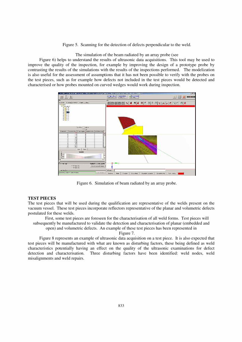
The simulation of the beam radiated by an array probe (see
Figure 6) helps to understand the results of ultrasonic data acquisitions. This tool may be used to
improve the quality of the inspection, for example by improving the design of a prototype probe by
contrasting the results of the simulations with the results of the inspections performed. The modelization
is also useful for the assessment of assumptions that it has not been possible to verify with the probes on
the test pieces, such as for example how defects not included in the test pieces would be detected and
characterised or how probes mounted on curved wedges would work during inspection.
Figure 6. Simulation of beam radiated by an array probe.
TEST PIECES
The test pieces that will be used during the qualification are representative of the welds present on the
vacuum vessel. These test pieces incorporate reflectors representative of the planar and volumetric defects
postulated for these welds.
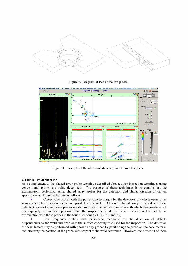
First, some test pieces are foreseen for the characterisation of all weld forms. Test pieces will
subsequently be manufactured to validate the detection and characterisation of planar (embedded and
open) and volumetric defects. An example of these test pieces has been represented in
Figure 7.
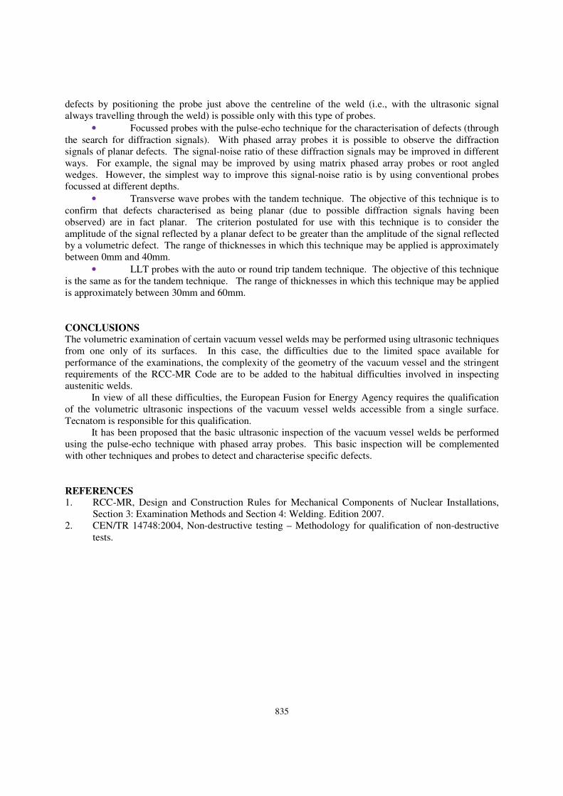
Figure 8 represents an example of ultrasonic data acquisition on a test piece. It is also expected that
test pieces will be manufactured with what are known as disturbing factors, these being defined as weld
characteristics potentially having an effect on the quality of the ultrasonic examinations for defect
detection and characterisation. Three disturbing factors have been identified: weld nodes, weld
misalignments and weld repairs.
834
Figure 7. Diagram of two of the test pieces.
Figure 8. Example of the ultrasonic data acquired from a test piece.
OTHER TECHNIQUES
As a complement to the phased array probe technique described above, other inspection techniques using
conventional probes are being developed. The purpose of these techniques is to complement the
examinations performed using phased array probes for the detection and characterisation of certain
specific cases. These probes are as follows:
• Creep wave probes with the pulse-echo technique for the detection of defects open to the
scan surface, both perpendicular and parallel to the weld. Although phased array probes detect these
defects, the use of creep wave probes notably improves the signal-noise ratio with which they are detected.
Consequently, it has been proposed that the inspection of all the vacuum vessel welds include an
examination with these probes in the four directions (Y+, Y-, X+ and X-).
• Low frequency probes with pulse-echo technique for the detection of defects
perpendicular to the weld and open onto the surface opposing that used for the inspection. The detection
of these defects may be performed with phased array probes by positioning the probe on the base material
and orienting the position of the probe with respect to the weld centreline. However, the detection of these
835
defects by positioning the probe just above the centreline of the weld (i.e., with the ultrasonic signal
always travelling through the weld) is possible only with this type of probes.
• Focussed probes with the pulse-echo technique for the characterisation of defects (through
the search for diffraction signals). With phased array probes it is possible to observe the diffraction
signals of planar defects. The signal-noise ratio of these diffraction signals may be improved in different
ways. For example, the signal may be improved by using matrix phased array probes or root angled
wedges. However, the simplest way to improve this signal-noise ratio is by using conventional probes
focussed at different depths.
• Transverse wave probes with the tandem technique. The objective of this technique is to
confirm that defects characterised as being planar (due to possible diffraction signals having been
observed) are in fact planar. The criterion postulated for use with this technique is to consider the
amplitude of the signal reflected by a planar defect to be greater than the amplitude of the signal reflected
by a volumetric defect. The range of thicknesses in which this technique may be applied is approximately
between 0mm and 40mm.
• LLT probes with the auto or round trip tandem technique. The objective of this technique
is the same as for the tandem technique. The range of thicknesses in which this technique may be applied
is approximately between 30mm and 60mm.
CONCLUSIONS
The volumetric examination of certain vacuum vessel welds may be performed using ultrasonic techniques
from one only of its surfaces. In this case, the difficulties due to the limited space available for
performance of the examinations, the complexity of the geometry of the vacuum vessel and the stringent
requirements of the RCC-MR Code are to be added to the habitual difficulties involved in inspecting
austenitic welds.
In view of all these difficulties, the European Fusion for Energy Agency requires the qualification
of the volumetric ultrasonic inspections of the vacuum vessel welds accessible from a single surface.
Tecnatom is responsible for this qualification.
It has been proposed that the basic ultrasonic inspection of the vacuum vessel welds be performed
using the pulse-echo technique with phased array probes. This basic inspection will be complemented
with other techniques and probes to detect and characterise specific defects.
REFERENCES
1. RCC-MR, Design and Construction Rules for Mechanical Components of Nuclear Installations,
Section 3: Examination Methods and Section 4: Welding. Edition 2007.
2. CEN/TR 14748:2004, Non-destructive testing – Methodology for qualification of non-destructive
tests.