inspection manual
DESCRIPTION
IHI deck crane inspection manualTRANSCRIPT
Copyright © 2014 IHI Corporation All Rights Reserved.
IHI DECK CRANE
MAINTENANCE AND INSPECTION MANUAL
1. NOTICE
2Copyright © 2014 IHI Corporation All Rights Reserved.
Please keep the following when proceeding with maintenance or inspection.
CAUTION
1. The crane should be rested without cargo when proceeding with maintenance or inspection.
2. Both SOURCE SWITCHES for the main and auxiliary circuit of the crane should be securely turned to “OFF”, on the control panel in the engine room. (In this case, suspend the “Under inspection” caution plate.)
3. Never adjust the safety devices, timer, hydraulic valve or brake device(s) for no reason at all.
4. Never replace, disassemble or adjust the HYDRAULIC PUMP and MOTOR without contacting IHI SERVICE NETWORK.
!
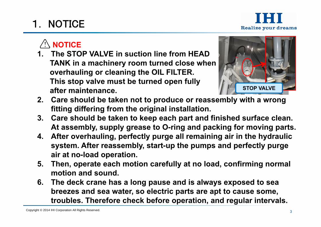
NOTICE1. The STOP VALVE in suction line from HEAD
TANK in a machinery room turned close whenoverhauling or cleaning the OIL FILTER.This stop valve must be turned open fullyafter maintenance.
2. Care should be taken not to produce or reassembly with a wrongfitting differing from the original installation.
3. Care should be taken to keep each part and finished surface clean. At assembly, supply grease to O-ring and packing for moving parts.
4. After overhauling, perfectly purge all remaining air in the hydraulic system. After reassembly, start-up the pumps and perfectly purge air at no-load operation.
5. Then, operate each motion carefully at no load, confirming normalmotion and sound.
6. The deck crane has a long pause and is always exposed to seabreezes and sea water, so electric parts are apt to cause some, troubles. Therefore check before operation, and regular intervals.
1. NOTICE
3
!
Copyright © 2014 IHI Corporation All Rights Reserved.
STOP VALVE
10
9
2. MACHINERY AND HYDRAULIC PARTS
4
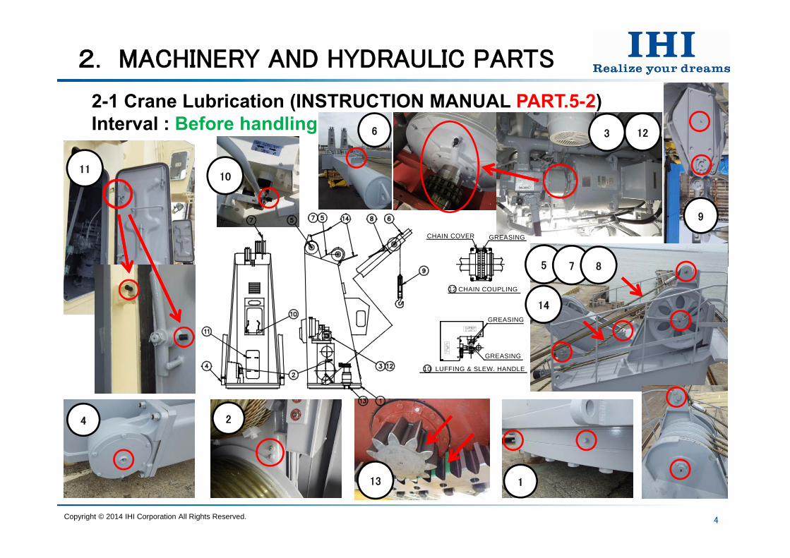
2-1 Crane Lubrication (INSTRUCTION MANUAL PART.5-2) Interval : Before handling
Copyright © 2014 IHI Corporation All Rights Reserved.
4 2
1
11
123
13
6
12 CHAIN COUPLING
CHAIN COVER GREASING
10 LUFFING & SLEW. HANDLE
GREASING
GREASING
5 7 8
14
2. MACHINERY AND HYDRAULIC PARTS
5
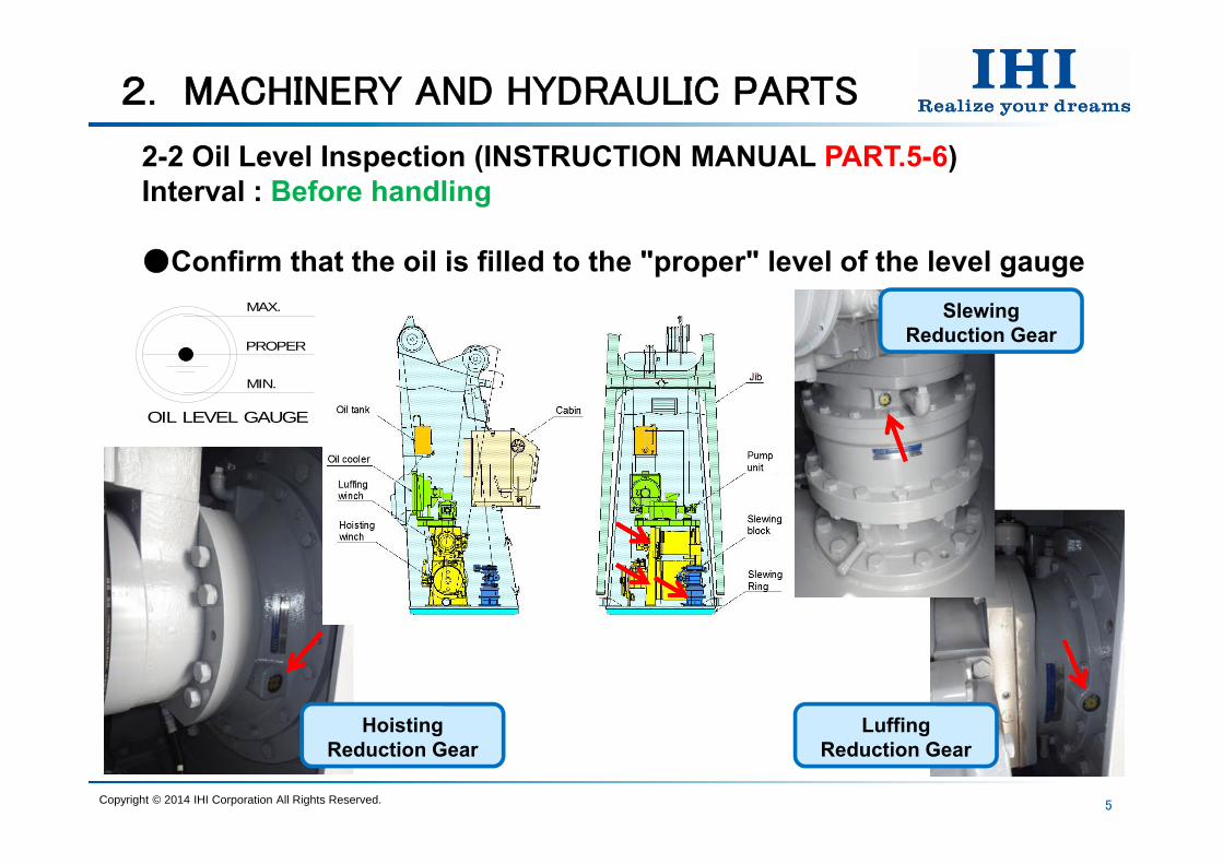
2-2 Oil Level Inspection (INSTRUCTION MANUAL PART.5-6) Interval : Before handling
Confirm that the oil is filled to the "proper" level of the level gauge
OIL LEVEL GAUGE
MAX.
PROPER
MIN.
Copyright © 2014 IHI Corporation All Rights Reserved.
HoistingReduction Gear
LuffingReduction Gear
SlewingReduction Gear

2. MACHINERY AND HYDRAULIC PARTS
6
2-3 Slewing Gear Lubrication (INSTRUCTION MANUAL PART.5-6) Interval : Before handling
Make a clean sweep of the stale oil on the gear and the pinion.Check the contact-surfaces of teeth (if damage such as pitching,
is found, this will require repair).Brush or spray with the recommended new oil to both surfaces of
the gear and pinion.
Copyright © 2014 IHI Corporation All Rights Reserved.
2. MACHINERY AND HYDRAULIC PARTS
7
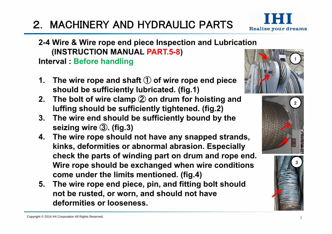
2-4 Wire & Wire rope end piece Inspection and Lubrication(INSTRUCTION MANUAL PART.5-8)
Interval : Before handling
1. The wire rope and shaft ① of wire rope end piece should be sufficiently lubricated. (fig.1)
2. The bolt of wire clamp ② on drum for hoisting and luffing should be sufficiently tightened. (fig.2)
3. The wire end should be sufficiently bound by the seizing wire ③. (fig.3)
4. The wire rope should not have any snapped strands, kinks, deformities or abnormal abrasion. Especially check the parts of winding part on drum and rope end. Wire rope should be exchanged when wire conditions come under the limits mentioned. (fig.4)
5. The wire rope end piece, pin, and fitting bolt should not be rusted, or worn, and should not have deformities or looseness.
Copyright © 2014 IHI Corporation All Rights Reserved.
1
2
3

2. MACHINERY AND HYDRAULIC PARTS
8
2-4 Wire & Wire rope end piece Inspection and Lubrication
DANGERIn case that maintain wire rope and wire rope end piece, be caution about fire and ventilation.
CAUTIONIf the oil with wire rope get less, apply the proper oil.
DANGERWire rope should be exchanged when wire rope conditions come under the limits mentioned on INSTRUCTIN MANUAL PART.5-8 JUDGEMENT.
!
!
!
Copyright © 2014 IHI Corporation All Rights Reserved.

2. MACHINERY AND HYDRAULIC PARTS
9
2-4 Wire & Wire rope end piece Inspection and LubricationThe end times to exchange wire rope are given by Labor Safety Regulations in JAPAN as follows :
When the individual wires of wire rope have snapped over 10% of the total number of wires in 1 pitch or over 5% of one strand of wire rope in 1 pitch. (Refer to P.5-21)When the individual wires of wire rope have snapped over 20% of the total number of wire rope in 5 pitch. (Refer to P.5-21)When the outer-diameter of wire rope has come to be worn up to 7% less the original diameter. (Refer to P.5-22 and 23)If wire rope has a kink, deformity, or abnormal wear.If wire rope is corroded as follows.
a)Wires are petted to pockmark.b)Core is completely corroded and outer wires are loosed.
Copyright © 2014 IHI Corporation All Rights Reserved.
2. MACHINERY AND HYDRAULIC PARTS
10
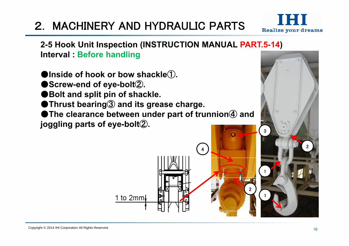
2-5 Hook Unit Inspection (INSTRUCTION MANUAL PART.5-14) Interval : Before handling
Inside of hook or bow shackle①.Screw-end of eye-bolt②. Bolt and split pin of shackle. Thrust bearing③ and its grease charge.The clearance between under part of trunnion④ and joggling parts of eye-bolt②.
Copyright © 2014 IHI Corporation All Rights Reserved.
1
1
2
3
2
4

11
2. MACHINERY AND HYDRAULIC PARTS
2-5 Hook Unit Inspection (INSTRUCTION MANUAL PART.5-14) Interval : Before handling
CAUTIONThe hook and shackle will wear out, creating grooves or openings by the rubbing from loads when used for a long time. Also, fatigue hardness due to long periods of use may harden and make the material brittle, resulting in cracking. Therefore, besides periodical inspection, carry out a non-destructive test once a year.
!
Copyright © 2014 IHI Corporation All Rights Reserved.
12
2. MACHINERY AND HYDRAULIC PARTS
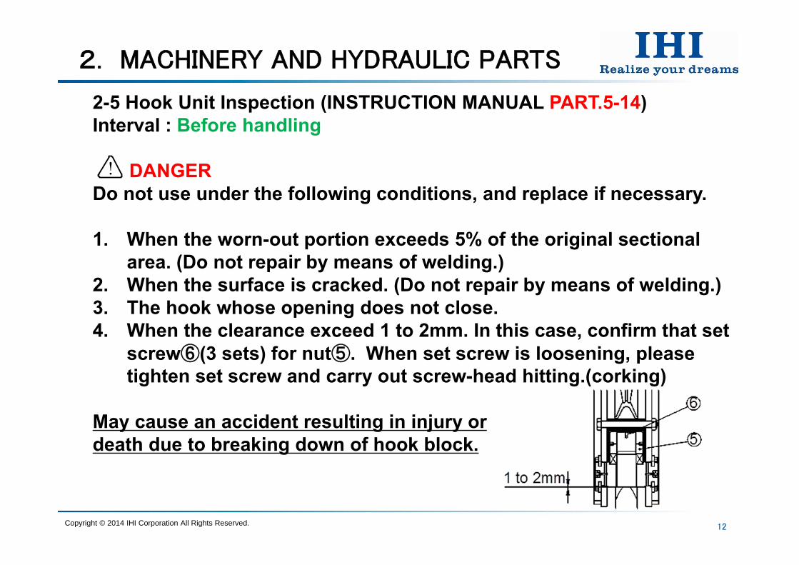
2-5 Hook Unit Inspection (INSTRUCTION MANUAL PART.5-14) Interval : Before handling
DANGERDo not use under the following conditions, and replace if necessary.
1. When the worn-out portion exceeds 5% of the original sectional area. (Do not repair by means of welding.)
2. When the surface is cracked. (Do not repair by means of welding.)3. The hook whose opening does not close.4. When the clearance exceed 1 to 2mm. In this case, confirm that set
screw⑥(3 sets) for nut⑤. When set screw is loosening, please tighten set screw and carry out screw-head hitting.(corking)
May cause an accident resulting in injury or death due to breaking down of hook block.
!
Copyright © 2014 IHI Corporation All Rights Reserved.
2. MACHINERY AND HYDRAULIC PARTS
13
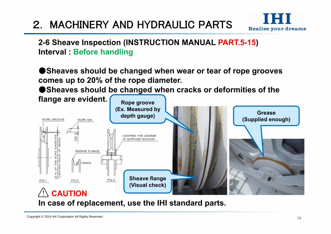
2-6 Sheave Inspection (INSTRUCTION MANUAL PART.5-15) Interval : Before handling
Sheaves should be changed when wear or tear of rope grooves comes up to 20% of the rope diameter.Sheaves should be changed when cracks or deformities of the flange are evident.
CAUTIONIn case of replacement, use the IHI standard parts. !
Copyright © 2014 IHI Corporation All Rights Reserved.
Rope groove(Ex. Measured by
depth gauge)
Sheave flange(Visual check)
Grease(Supplied enough)
2. MACHINERY AND HYDRAULIC PARTS
14
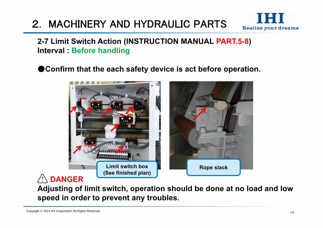
2-7 Limit Switch Action (INSTRUCTION MANUAL PART.5-8) Interval : Before handling
Confirm that the each safety device is act before operation.
DANGERAdjusting of limit switch, operation should be done at no load and low speed in order to prevent any troubles.
!
Copyright © 2014 IHI Corporation All Rights Reserved.
Rope slackLimit switch box(See finished plan)
2. MACHINERY AND HYDRAULIC PARTS
15
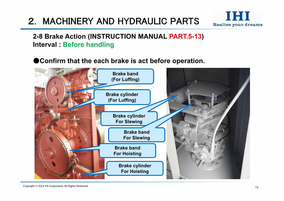
2-8 Brake Action (INSTRUCTION MANUAL PART.5-13) Interval : Before handling
Confirm that the each brake is act before operation.
Copyright © 2014 IHI Corporation All Rights Reserved.
Brake bandFor Hoisting
Brake band(For Luffing)
Brake cylinderFor Hoisting
Brake cylinder(For Luffing)
Brake cylinderFor Slewing
Brake bandFor Slewing
2. MACHINERY AND HYDRAULIC PARTS
16
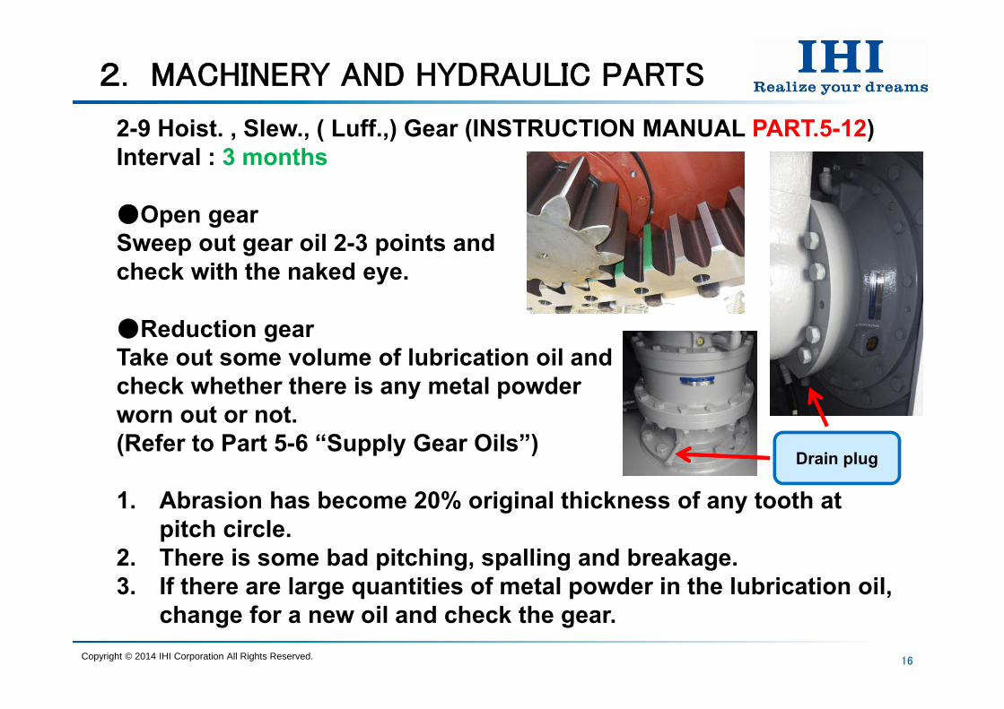
2-9 Hoist. , Slew., ( Luff.,) Gear (INSTRUCTION MANUAL PART.5-12) Interval : 3 months
Open gearSweep out gear oil 2-3 points and check with the naked eye.
Reduction gearTake out some volume of lubrication oil and check whether there is any metal powder worn out or not.(Refer to Part 5-6 “Supply Gear Oils”)
1. Abrasion has become 20% original thickness of any tooth at pitch circle.
2. There is some bad pitching, spalling and breakage.3. If there are large quantities of metal powder in the lubrication oil,
change for a new oil and check the gear.Copyright © 2014 IHI Corporation All Rights Reserved.
Drain plug
2. MACHINERY AND HYDRAULIC PARTS
17
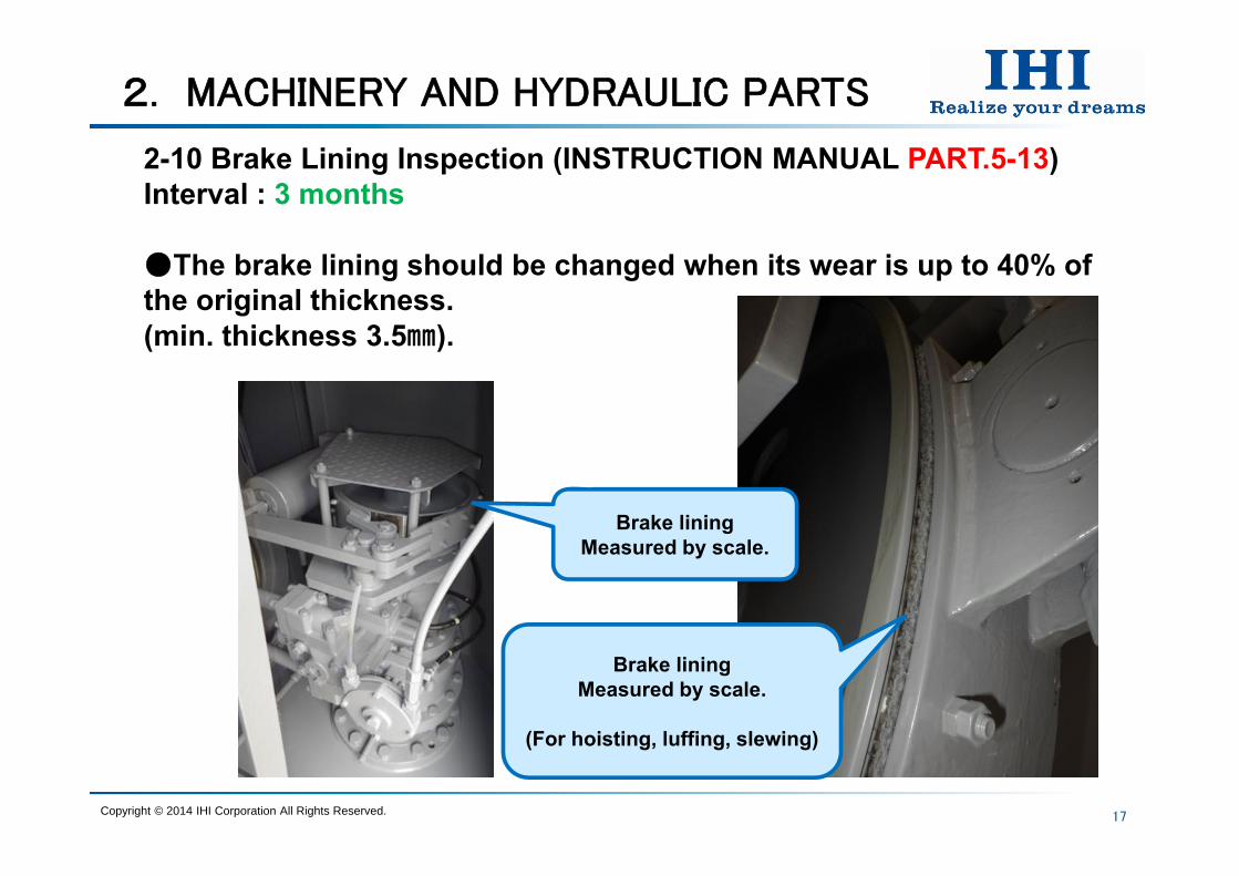
2-10 Brake Lining Inspection (INSTRUCTION MANUAL PART.5-13) Interval : 3 months
The brake lining should be changed when its wear is up to 40% of the original thickness.(min. thickness 3.5).
Copyright © 2014 IHI Corporation All Rights Reserved.
Brake liningMeasured by scale.
(For hoisting, luffing, slewing)
Brake liningMeasured by scale.
2. MACHINERY AND HYDRAULIC PARTS
18
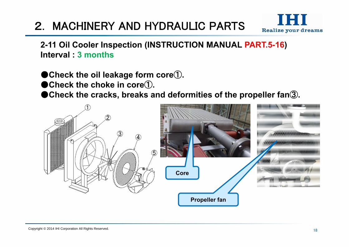
2-11 Oil Cooler Inspection (INSTRUCTION MANUAL PART.5-16) Interval : 3 months
Check the oil leakage form core①.Check the choke in core①.Check the cracks, breaks and deformities of the propeller fan③.
Copyright © 2014 IHI Corporation All Rights Reserved.
Core
Propeller fan

2. MACHINERY AND HYDRAULIC PARTS
19
2-12 Geared Cable Inspection (INSTRUCTION MANUAL PART.5-10) Interval : 3 months
When the special cable wears out more than 1 in Dia.(Original cable Dia. 7.95)
When the spiral cable breaks, or when there are more than 2 center wire break.
CAUTIONIn case of adjusting, maintenance and exchanging, crane keep stop.!
Copyright © 2014 IHI Corporation All Rights Reserved.
Geared cableHoist. Luff. Slew.
Special cable(In the plastic tube)
Spiral cable

2. MACHINERY AND HYDRAULIC PARTS
20
2-13 Chain Coupling Grease (INSTRUCTION MANUAL PART.5-2) Interval : 6 months
Copyright © 2014 IHI Corporation All Rights Reserved.
Grease(By brush)
2. MACHINERY AND HYDRAULIC PARTS
21
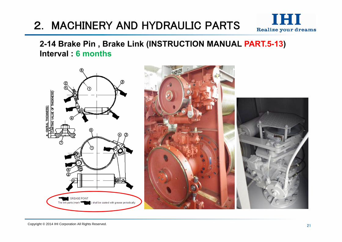
2-14 Brake Pin , Brake Link (INSTRUCTION MANUAL PART.5-13) Interval : 6 months
Copyright © 2014 IHI Corporation All Rights Reserved.

2. MACHINERY AND HYDRAULIC PARTS
22
2-15 Control Handle Inspection(INSTRUCTION MANUAL PART.2-6/5-10) Interval : 6 months
The neutral position of the control handle.
Copyright © 2014 IHI Corporation All Rights Reserved.
Luffing & Slewing(Universal handle)
Hoisting(Vertical handle)
Grease point
2. MACHINERY AND HYDRAULIC PARTS
23
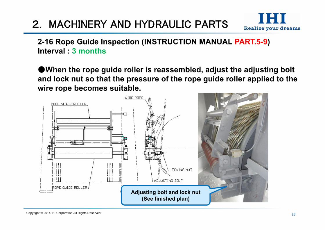
2-16 Rope Guide Inspection (INSTRUCTION MANUAL PART.5-9) Interval : 3 months
When the rope guide roller is reassembled, adjust the adjusting bolt and lock nut so that the pressure of the rope guide roller applied to the wire rope becomes suitable.
Copyright © 2014 IHI Corporation All Rights Reserved.
Adjusting bolt and lock nut(See finished plan)
2. MACHINERY AND HYDRAULIC PARTS
24
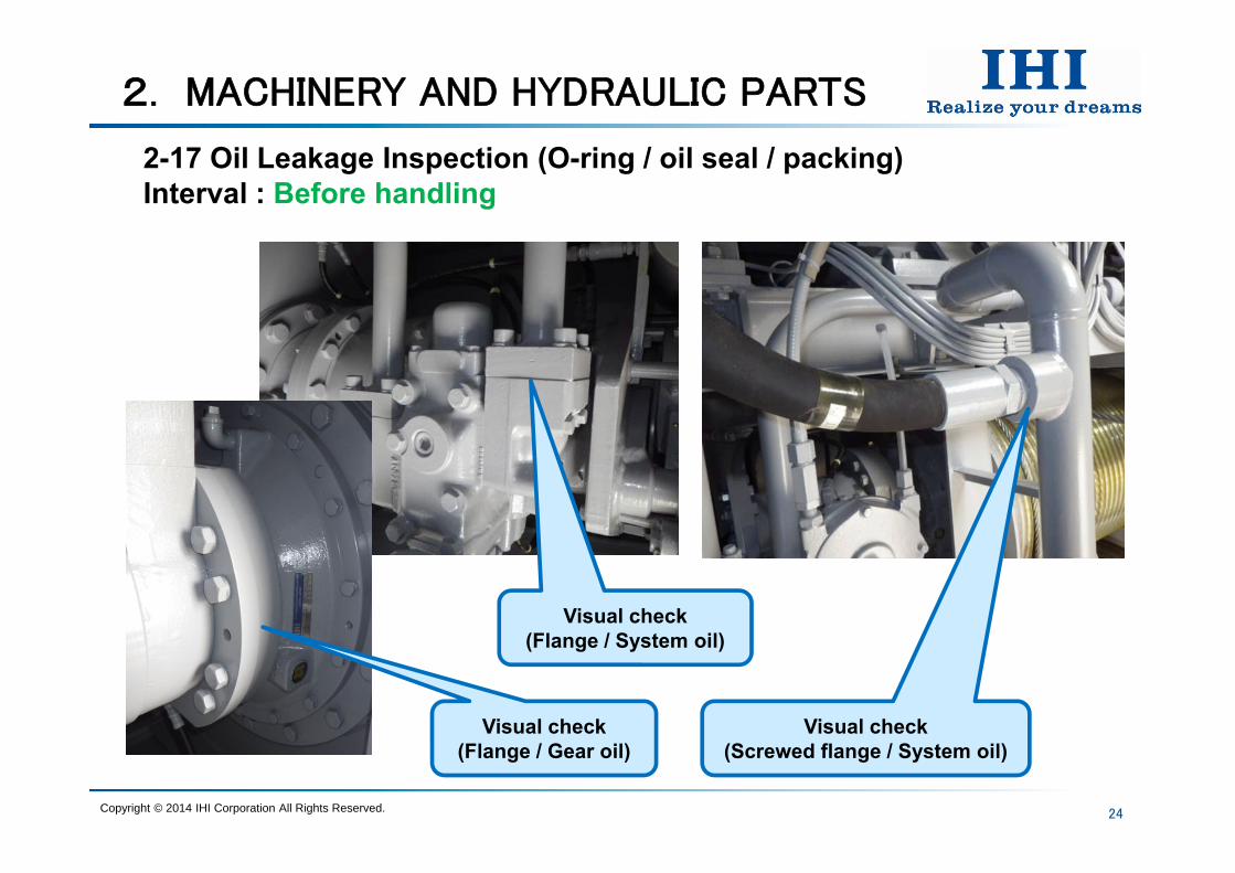
2-17 Oil Leakage Inspection (O-ring / oil seal / packing) Interval : Before handling
Copyright © 2014 IHI Corporation All Rights Reserved.
Visual check(Screwed flange / System oil)
Visual check(Flange / System oil)
Visual check(Flange / Gear oil)
2. MACHINERY AND HYDRAULIC PARTS
25
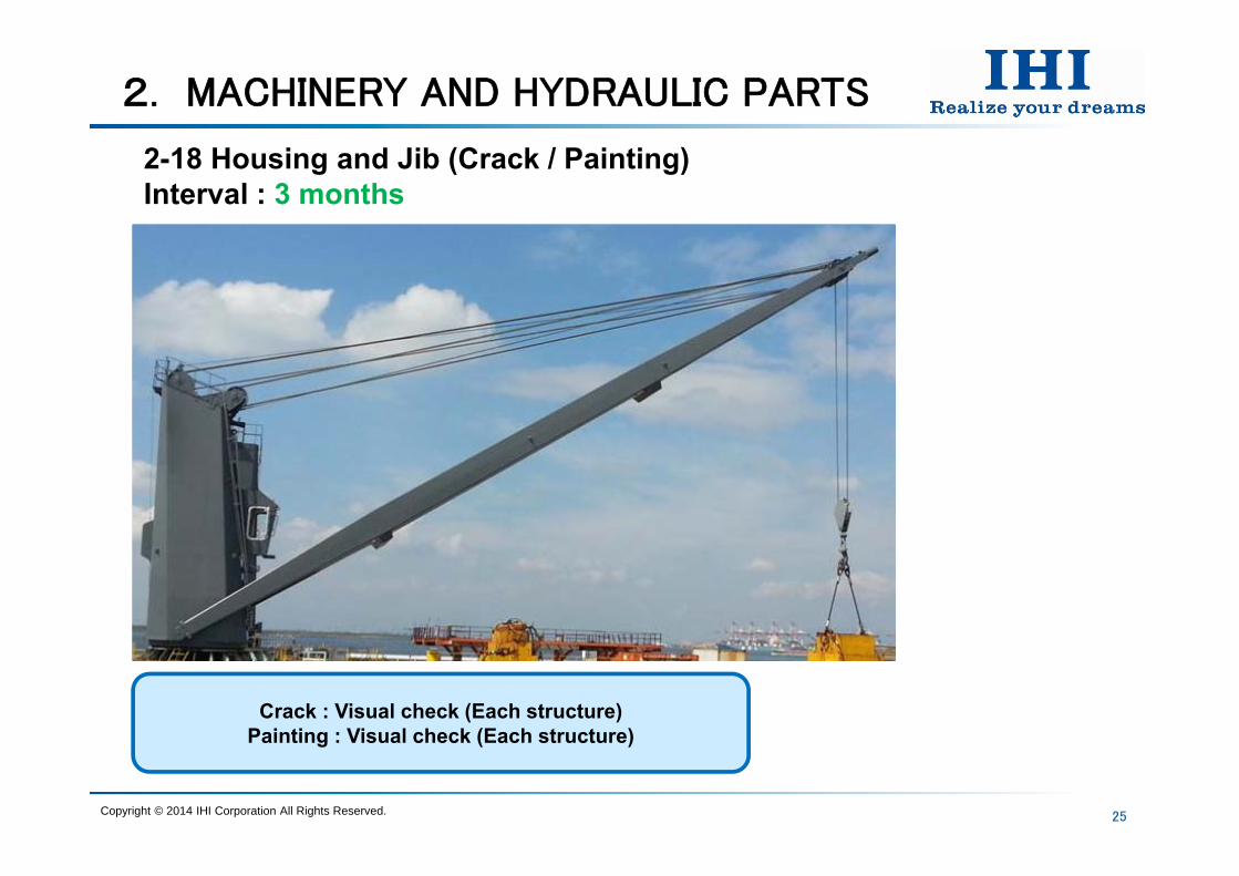
2-18 Housing and Jib (Crack / Painting) Interval : 3 months
Copyright © 2014 IHI Corporation All Rights Reserved.
Crack : Visual check (Each structure)Painting : Visual check (Each structure)

2. MACHINERY AND HYDRAULIC PARTS
26
2-19 Bolts for Machine Inspection (Loosened or not) Interval : 3 months
In case that the paint film is broken at the tightening point and / or hammering sound is dull, bolts and nuts may be loose, then, they should be tightened.
Copyright © 2014 IHI Corporation All Rights Reserved.
Fitting bolts ofwinch frame
Fitting bolts ofDrum bearing(Hoist. / Luff.)
Tightening bolt of wire clamp
(Hoist. / Luff.)

2. MACHINERY AND HYDRAULIC PARTS
27
2-20 Foundation Bolt Inspection (Loosened or not) Interval : 3 months
In case that the paint film is broken at the tightening point and / or hammering sound is dull, bolts and nuts may be loose, then, they should be tightened.
Copyright © 2014 IHI Corporation All Rights Reserved.
Slewing ring fitting bolts(Lower parts of slewing ring)
Crane anchor bolts(Post flange)
Fitting bolts of jib
Fitting bolts of shaft end for wire rope end piece
2. MACHINERY AND HYDRAULIC PARTS
28
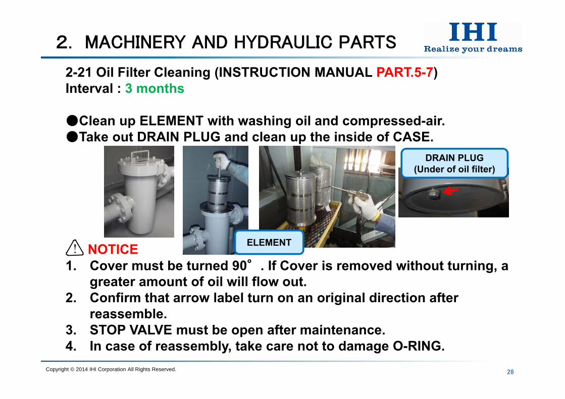
2-21 Oil Filter Cleaning (INSTRUCTION MANUAL PART.5-7) Interval : 3 months
Clean up ELEMENT with washing oil and compressed-air.Take out DRAIN PLUG and clean up the inside of CASE.
NOTICE1. Cover must be turned 90°. If Cover is removed without turning, a
greater amount of oil will flow out.2. Confirm that arrow label turn on an original direction after
reassemble.3. STOP VALVE must be open after maintenance.4. In case of reassembly, take care not to damage O-RING.
!
Copyright © 2014 IHI Corporation All Rights Reserved.
DRAIN PLUG(Under of oil filter)
ELEMENT
2. MACHINERY AND HYDRAULIC PARTS
29
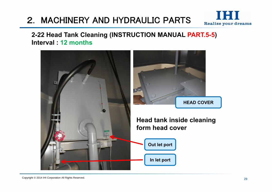
2-22 Head Tank Cleaning (INSTRUCTION MANUAL PART.5-5) Interval : 12 months
Head tank inside cleaningform head cover
Copyright © 2014 IHI Corporation All Rights Reserved.
HEAD COVER
Out let port
In let port
2. MACHINERY AND HYDRAULIC PARTS
30
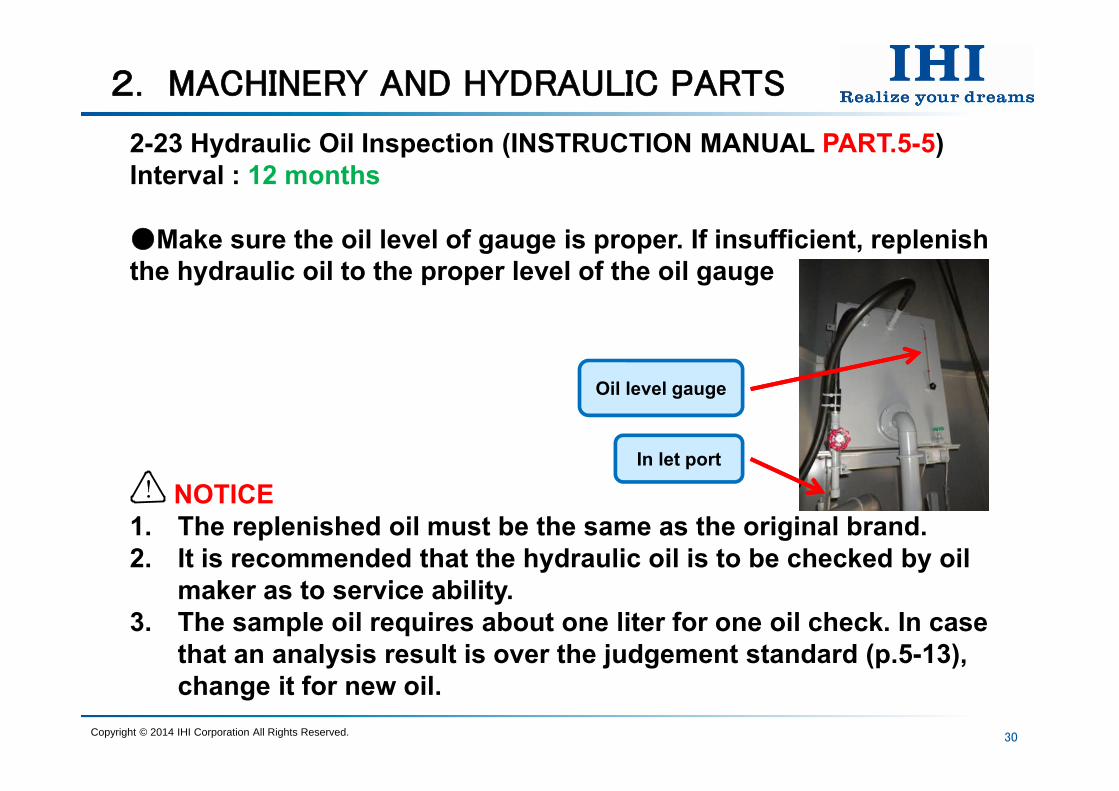
2-23 Hydraulic Oil Inspection (INSTRUCTION MANUAL PART.5-5) Interval : 12 months
Make sure the oil level of gauge is proper. If insufficient, replenish the hydraulic oil to the proper level of the oil gauge
NOTICE1. The replenished oil must be the same as the original brand.2. It is recommended that the hydraulic oil is to be checked by oil
maker as to service ability.3. The sample oil requires about one liter for one oil check. In case
that an analysis result is over the judgement standard (p.5-13), change it for new oil.
!
Copyright © 2014 IHI Corporation All Rights Reserved.
Oil level gauge
In let port
2. MACHINERY AND HYDRAULIC PARTS
31
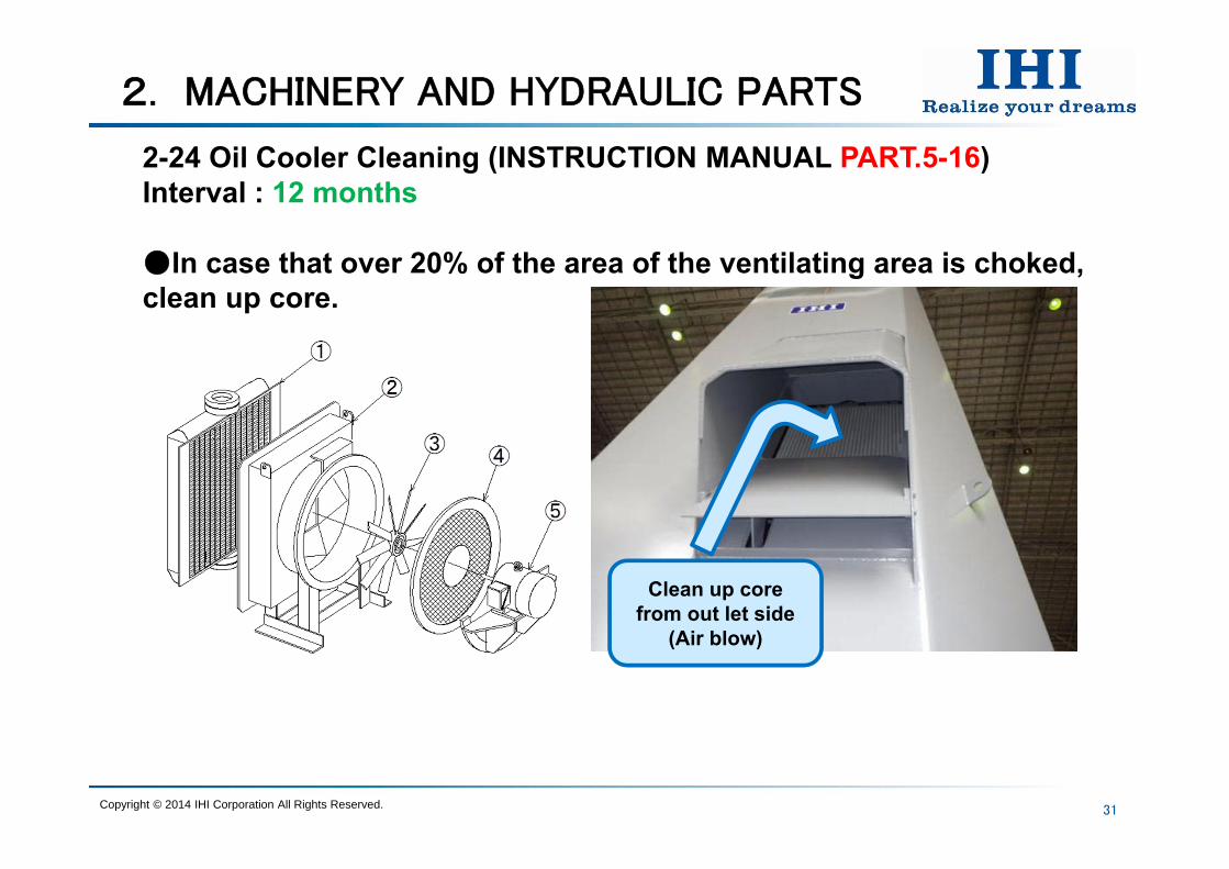
2-24 Oil Cooler Cleaning (INSTRUCTION MANUAL PART.5-16) Interval : 12 months
In case that over 20% of the area of the ventilating area is choked, clean up core.
Copyright © 2014 IHI Corporation All Rights Reserved.
Clean up core from out let side
(Air blow)
2. MACHINERY AND HYDRAULIC PARTS
32
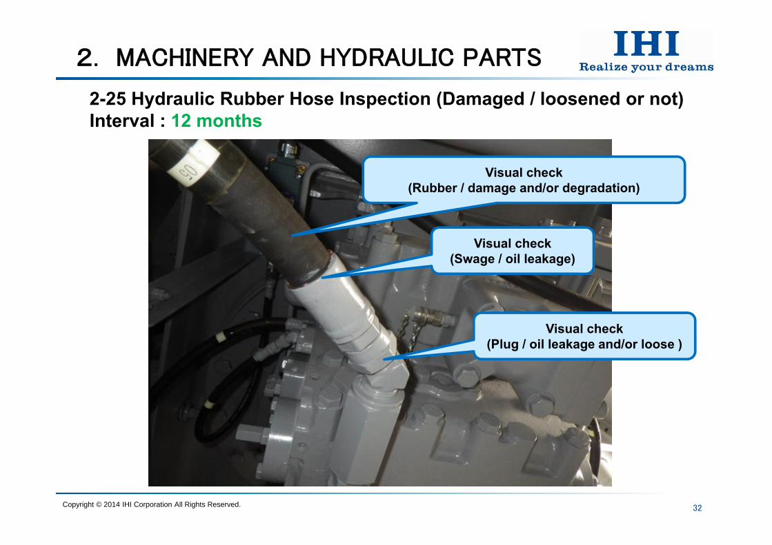
2-25 Hydraulic Rubber Hose Inspection (Damaged / loosened or not) Interval : 12 months
Copyright © 2014 IHI Corporation All Rights Reserved.
Visual check(Rubber / damage and/or degradation)
Visual check(Swage / oil leakage)
Visual check(Plug / oil leakage and/or loose )
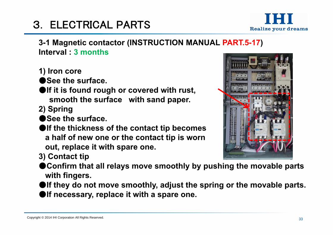
3-1 Magnetic contactor (INSTRUCTION MANUAL PART.5-17) Interval : 3 months
1) Iron coreSee the surface.If it is found rough or covered with rust,
smooth the surface with sand paper.2) SpringSee the surface.If the thickness of the contact tip becomes
a half of new one or the contact tip is wornout, replace it with spare one.
3) Contact tipConfirm that all relays move smoothly by pushing the movable parts
with fingers.If they do not move smoothly, adjust the spring or the movable parts.If necessary, replace it with a spare one.
3. ELECTRICAL PARTS
33Copyright © 2014 IHI Corporation All Rights Reserved.
3. ELECTRICAL PARTS
34
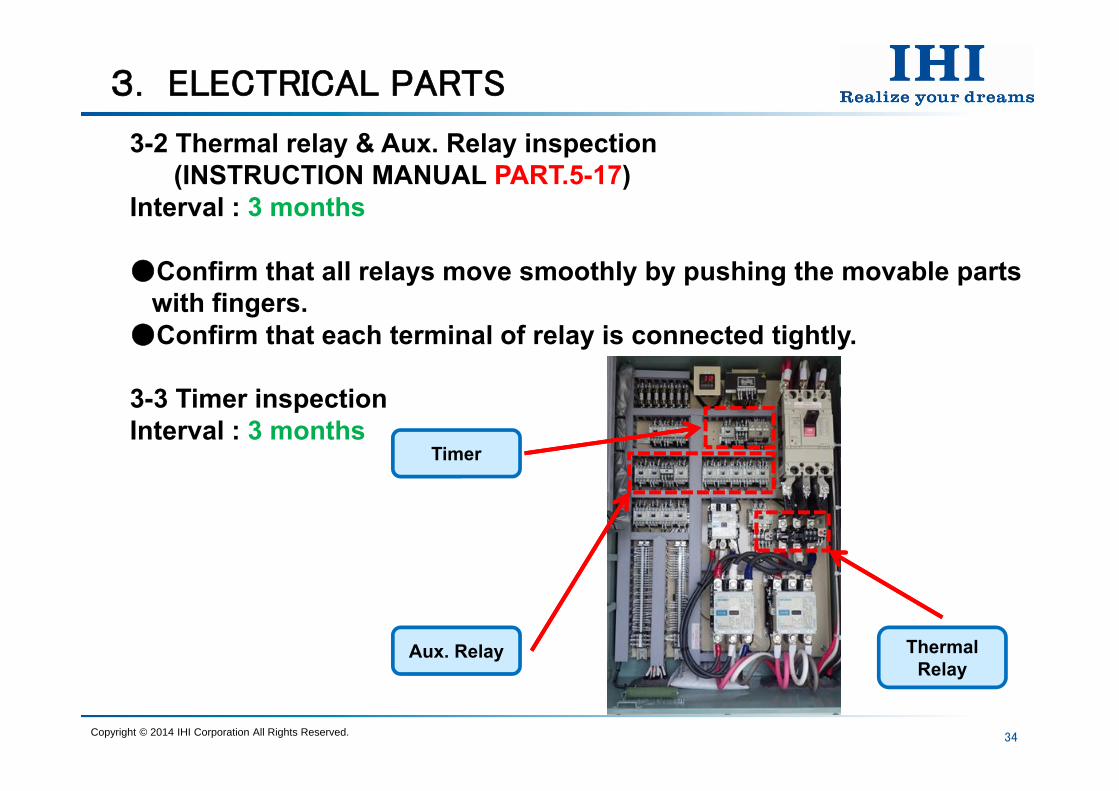
3-2 Thermal relay & Aux. Relay inspection (INSTRUCTION MANUAL PART.5-17)
Interval : 3 months
Confirm that all relays move smoothly by pushing the movable partswith fingers.
Confirm that each terminal of relay is connected tightly.
3-3 Timer inspection Interval : 3 months
Copyright © 2014 IHI Corporation All Rights Reserved.
Timer
Aux. Relay ThermalRelay

3. ELECTRICAL PARTS
35
3-4 Slipring (INSTRUCTION MANUAL PART.5-17) Interval : 3 months
1) Brush, holderCheck brush condition
2) Insulation resistanceMeasure it between earth and each phaseof main circuit, light. & heat. circuit. Measuring point : Secondary side of main switch of shipInsulation resistance : More than 10 MΩ( main )
More than 1 MΩ( light. & heat. )
3) Terminal fitting nutMake sure the terminal fitting nuts are tightened. If they are loose, fix them tightly. Check point : First and Secondary side terminal of slipring
Copyright © 2014 IHI Corporation All Rights Reserved.
Terminal fitting bolt
Brush holder
3. ELECTRICAL PARTS
36
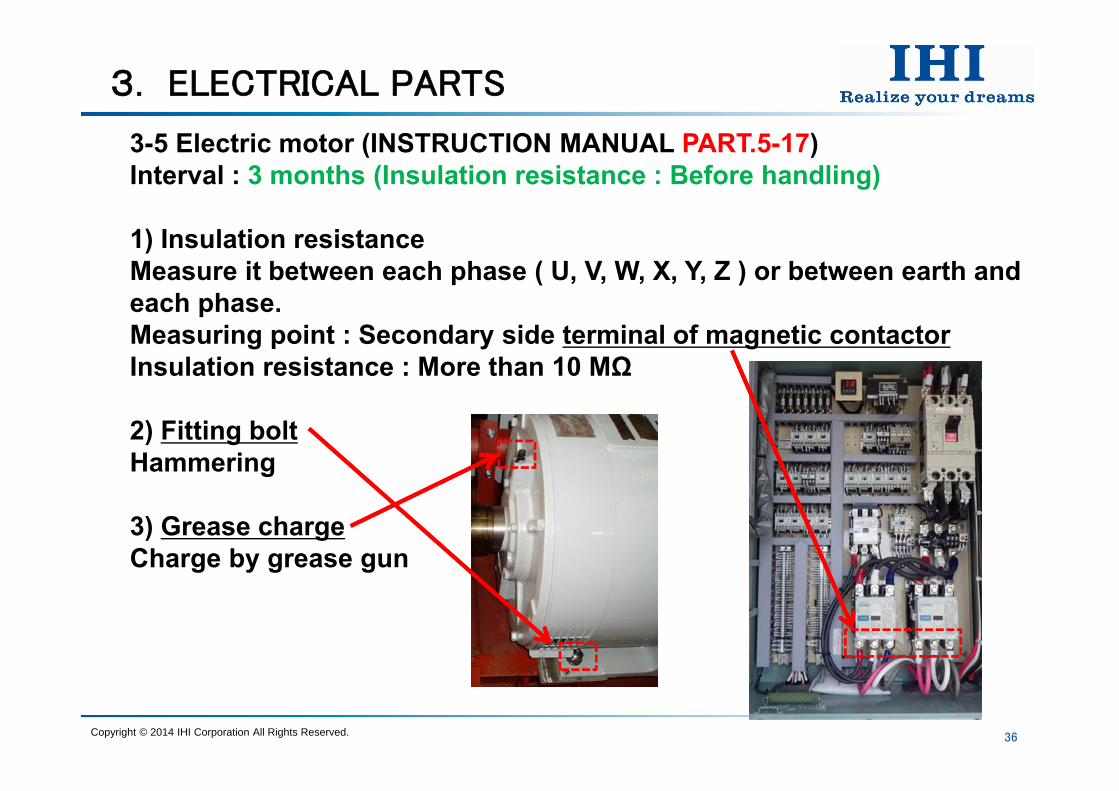
3-5 Electric motor (INSTRUCTION MANUAL PART.5-17) Interval : 3 months (Insulation resistance : Before handling)
1) Insulation resistanceMeasure it between each phase ( U, V, W, X, Y, Z ) or between earth and each phase.Measuring point : Secondary side terminal of magnetic contactorInsulation resistance : More than 10 MΩ
2) Fitting boltHammering
3) Grease chargeCharge by grease gun
Copyright © 2014 IHI Corporation All Rights Reserved.
3. ELECTRICAL PARTS
37
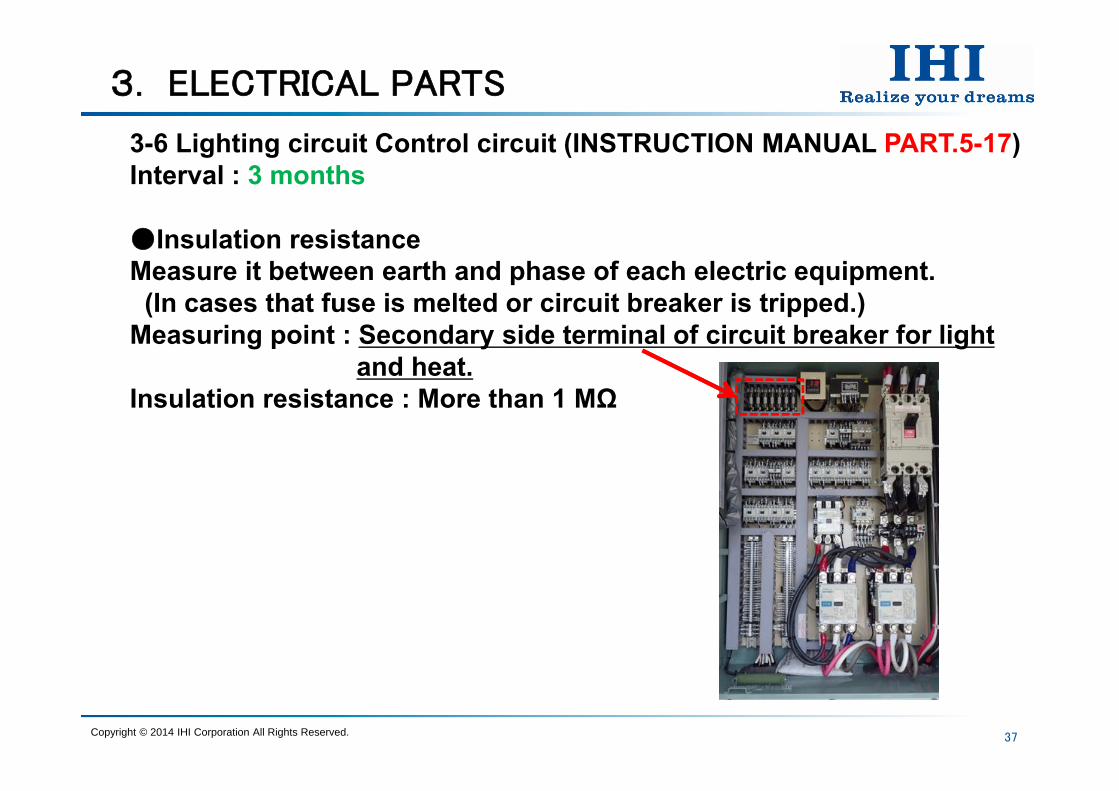
3-6 Lighting circuit Control circuit (INSTRUCTION MANUAL PART.5-17) Interval : 3 months
Insulation resistanceMeasure it between earth and phase of each electric equipment. (In cases that fuse is melted or circuit breaker is tripped.)
Measuring point : Secondary side terminal of circuit breaker for lightand heat.
Insulation resistance : More than 1 MΩ
Copyright © 2014 IHI Corporation All Rights Reserved.
3. ELECTRICAL PARTS
38
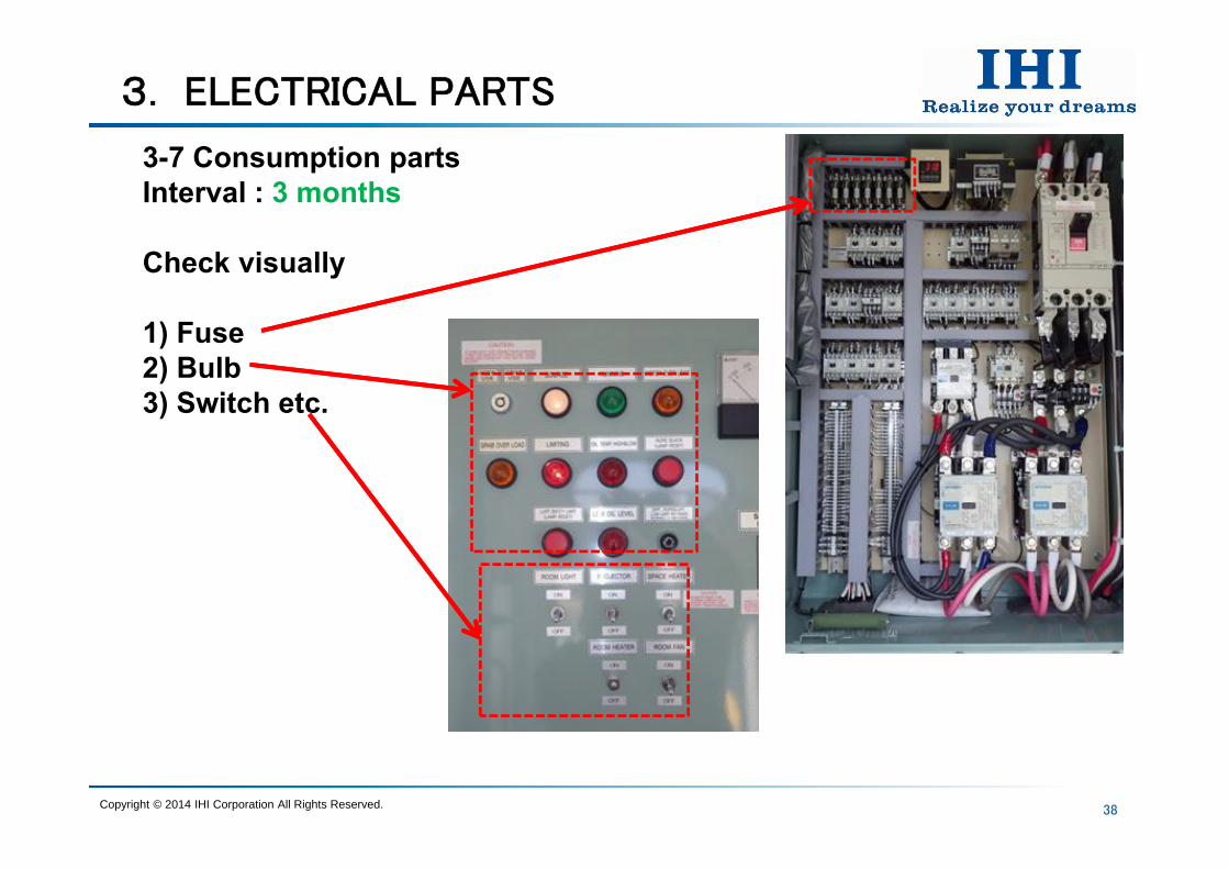
3-7 Consumption partsInterval : 3 months
Check visually
1) Fuse2) Bulb3) Switch etc.
Copyright © 2014 IHI Corporation All Rights Reserved.
39
4. NOTICE (OPERATION)
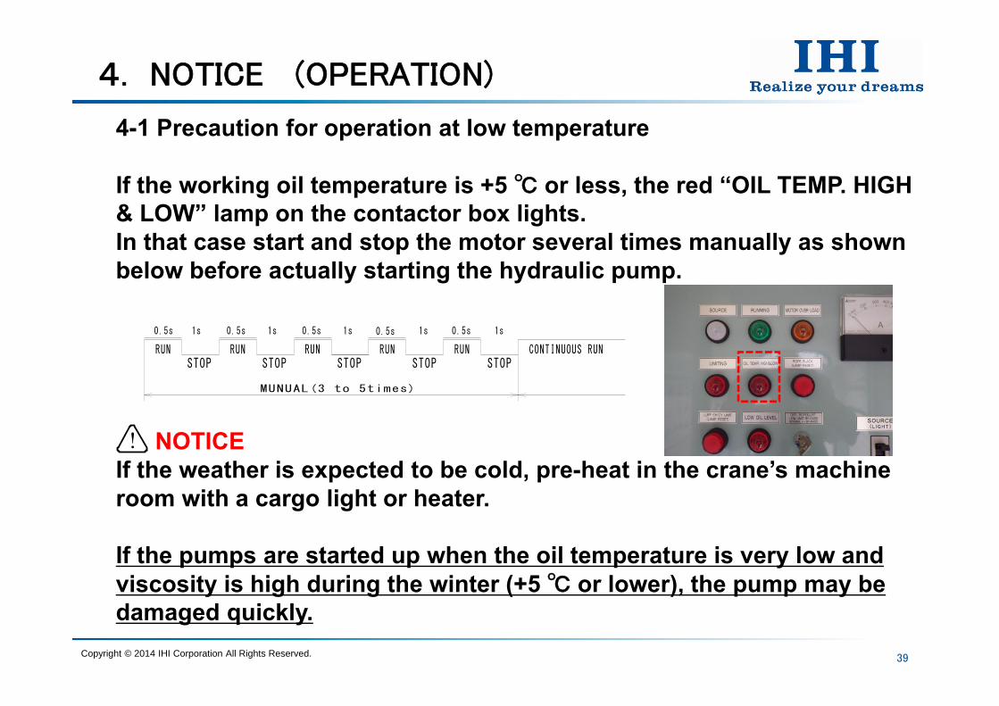
4-1 Precaution for operation at low temperature
If the working oil temperature is +5 or less, the red “OIL TEMP. HIGH & LOW” lamp on the contactor box lights.In that case start and stop the motor several times manually as shown below before actually starting the hydraulic pump.
NOTICEIf the weather is expected to be cold, pre-heat in the crane’s machine room with a cargo light or heater.
If the pumps are started up when the oil temperature is very low and viscosity is high during the winter (+5 or lower), the pump may be damaged quickly.
Copyright © 2014 IHI Corporation All Rights Reserved.
STOP STOP STOP STOP STOPRUN RUN RUN RUN RUN CONTINUOUS RUN
0.5s 1s 1s
MUNUAL(3 to 5times)
1s0.5s 0.5s 0.5s 0.5s1s 1s
!
40
4. NOTICE (OPERATION)
4-1 Precaution for operation at low temperature
Preparation of hydraulic motorWhen temperature of system oil became to allowable level for operation (above +5) after warming up of hydraulic pump and hydraulic circuit, the operation of each hydraulic motor should be carried out for preparation by following method.
NOTICE1. Run the hydraulic motor (hoisting, luffing and slewing) toward
normal and/or reverse rotation slowly (less than about 5 rpm) in about 2 or 3 seconds for more than 5 times.
2. And, after brief stop of the hydraulic motor for 1 minute, each motion should be carried out about several times.
The above operations have to be carried out independently without load to each motion.The hyd. motor may be damaged.
Copyright © 2014 IHI Corporation All Rights Reserved.
!
41
4. NOTICE (OPERATION)
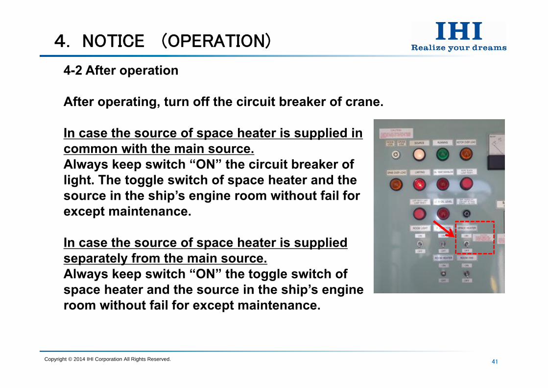
4-2 After operation
After operating, turn off the circuit breaker of crane.
In case the source of space heater is supplied in common with the main source.Always keep switch “ON” the circuit breaker of light. The toggle switch of space heater and the source in the ship’s engine room without fail for except maintenance.
In case the source of space heater is supplied separately from the main source.Always keep switch “ON” the toggle switch of space heater and the source in the ship’s engine room without fail for except maintenance.
Copyright © 2014 IHI Corporation All Rights Reserved.
42
5. IHI SERVICE NETWORK
Strength to support our users
Due to our long experience in the market, we have been able to develop our after-sales service and provide an enhanced response to your needs..We apply our own instruction facilities for hydraulic technology and have commit resources into training high-quality engineers.We will continue to strive to provide a better service to meet our customers constantly evolving needs.
If you have some difficult and trouble, please contact our service network. (Please see attached our service network.)
Copyright © 2014 IHI Corporation All Rights Reserved.
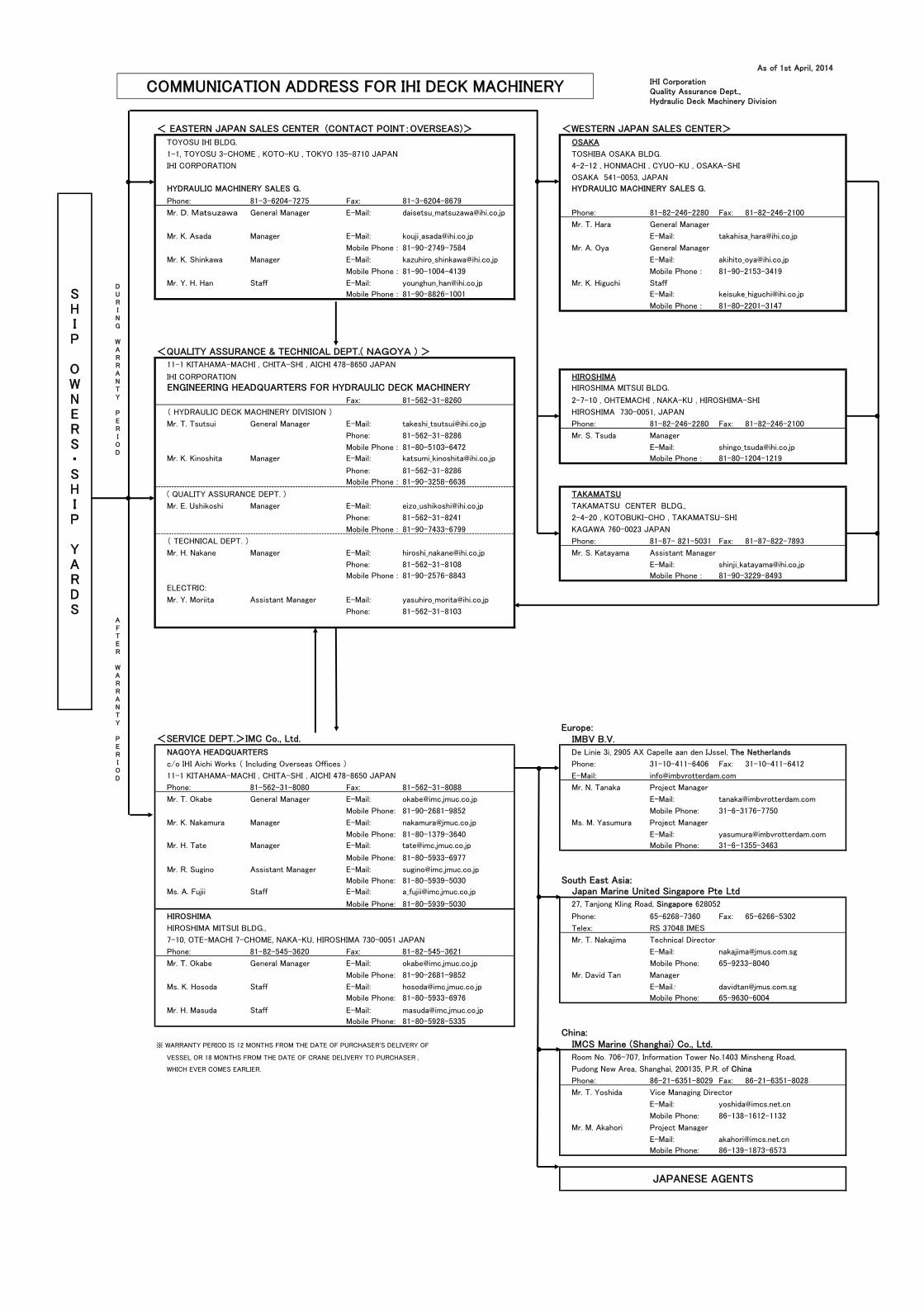
As of 1st April, 2014
IHI CorporationQuality Assurance Dept.,Hydraulic Deck Machinery Division
< EASTERN JAPAN SALES CENTER (CONTACT POINT:OVERSEAS)> <WESTERN JAPAN SALES CENTER>
TOYOSU IHI BLDG. OSAKA
1-1, TOYOSU 3-CHOME , KOTO-KU , TOKYO 135-8710 JAPAN TOSHIBA OSAKA BLDG.
IHI CORPORATION 4-2-12 , HONMACHI , CYUO-KU , OSAKA-SHI
OSAKA 541-0053, JAPAN
HYDRAULIC MACHINERY SALES G. HYDRAULIC MACHINERY SALES G.
Phone: 81-3-6204-7275 Fax: 81-3-6204-8679
Mr. D. Matsuzawa General Manager E-Mail: [email protected] Phone: 81-82-246-2280 Fax: 81-82-246-2100
Mr. T. Hara General Manager
Mr. K. Asada Manager E-Mail: [email protected] E-Mail: [email protected]
Mobile Phone : 81-90-2749-7584 Mr. A. Oya General Manager
Mr. K. Shinkawa Manager E-Mail: [email protected] E-Mail: [email protected]
Mobile Phone : 81-90-1004-4139 Mobile Phone : 81-90-2153-3419
Mr. Y. H. Han Staff E-Mail: [email protected] Mr. K. Higuchi Staff
Mobile Phone : 81-90-8826-1001 E-Mail: [email protected]
Mobile Phone : 81-80-2201-3147
<QUALITY ASSURANCE & TECHNICAL DEPT.( NAGOYA ) >
11-1 KITAHAMA-MACHI , CHITA-SHI , AICHI 478-8650 JAPAN
IHI CORPORATION HIROSHIMA
ENGINEERING HEADQUARTERS FOR HYDRAULIC DECK MACHINERY HIROSHIMA MITSUI BLDG.
Fax: 81-562-31-8260 2-7-10 , OHTEMACHI , NAKA-KU , HIROSHIMA-SHI
( HYDRAULIC DECK MACHINERY DIVISION ) HIROSHIMA 730-0051, JAPAN
Mr. T. Tsutsui General Manager E-Mail: [email protected] Phone: 81-82-246-2280 Fax: 81-82-246-2100
Phone: 81-562-31-8286 Mr. S. Tsuda Manager
Mobile Phone : 81-80-5103-6472 E-Mail: [email protected]
Mr. K. Kinoshita Manager E-Mail: [email protected] Mobile Phone : 81-80-1204-1219
Phone: 81-562-31-8286
Mobile Phone : 81-90-3258-6636
( QUALITY ASSURANCE DEPT. ) TAKAMATSU
Mr. E. Ushikoshi Manager E-Mail: [email protected] TAKAMATSU CENTER BLDG.,
Phone: 81-562-31-8241 2-4-20 , KOTOBUKI-CHO , TAKAMATSU-SHI
Mobile Phone : 81-90-7433-6799 KAGAWA 760-0023 JAPAN
( TECHNICAL DEPT. ) Phone: 81-87- 821-5031 Fax: 81-87-822-7893
Mr. H. Nakane Manager E-Mail: [email protected] Mr. S. Katayama Assistant Manager
Phone: 81-562-31-8108 E-Mail: [email protected]
Mobile Phone : 81-90-2576-8843 Mobile Phone : 81-90-3229-8493
ELECTRIC:
Mr. Y. Moriita Assistant Manager E-Mail: [email protected]
Phone: 81-562-31-8103
Europe:<SERVICE DEPT.>IMC Co., Ltd. IMBV B.V.
NAGOYA HEADQUARTERS De Linie 3i, 2905 AX Capelle aan den IJssel, The Netherlands
c/o IHI Aichi Works ( Including Overseas Offices ) Phone: 31-10-411-6406 Fax: 31-10-411-6412
11-1 KITAHAMA-MACHI , CHITA-SHI , AICHI 478-8650 JAPAN E-Mail: [email protected]
Phone: 81-562-31-8080 Fax: 81-562-31-8088 Mr. N. Tanaka Project Manager
Mr. T. Okabe General Manager E-Mail: [email protected] E-Mail: [email protected]
Mobile Phone: 81-90-2681-9852 Mobile Phone: 31-6-3176-7750
Mr. K. Nakamura Manager E-Mail: [email protected] Ms. M. Yasumura Project Manager
Mobile Phone: 81-80-1379-3640 E-Mail: [email protected]
Mr. H. Tate Manager E-Mail: [email protected] Mobile Phone: 31-6-1355-3463
Mobile Phone: 81-80-5933-6977
Mr. R. Sugino Assistant Manager E-Mail: [email protected]
Mobile Phone: 81-80-5939-5030 South East Asia:Ms. A. Fujii Staff E-Mail: [email protected] Japan Marine United Singapore Pte Ltd
Mobile Phone: 81-80-5939-5030 27, Tanjong Kling Road, Singapore 628052
HIROSHIMA Phone: 65-6268-7360 Fax: 65-6266-5302
HIROSHIMA MITSUI BLDG., Telex: RS 37048 IMES
7-10, OTE-MACHI 7-CHOME, NAKA-KU, HIROSHIMA 730-0051 JAPAN Mr. T. Nakajima Technical Director
Phone: 81-82-545-3620 Fax: 81-82-545-3621 E-Mail: [email protected]
Mr. T. Okabe General Manager E-Mail: [email protected] Mobile Phone: 65-9233-8040
Mobile Phone: 81-90-2681-9852 Mr. David Tan Manager
Ms. K. Hosoda Staff E-Mail: [email protected] E-Mail: [email protected]
Mobile Phone: 81-80-5933-6976 Mobile Phone: 65-9630-6004
Mr. H. Masuda Staff E-Mail: [email protected]
Mobile Phone: 81-80-5928-5335
China:※ WARRANTY PERIOD IS 12 MONTHS FROM THE DATE OF PURCHASER'S DELIVERY OF IMCS Marine (Shanghai) Co., Ltd.
VESSEL OR 18 MONTHS FROM THE DATE OF CRANE DELIVERY TO PURCHASER , Room No. 706-707, Information Tower No.1403 Minsheng Road,
WHICH EVER COMES EARLIER. Pudong New Area, Shanghai, 200135, P.R. of China
Phone: 86-21-6351-8029 Fax: 86-21-6351-8028
Mr. T. Yoshida Vice Managing Director
E-Mail: [email protected]
Mobile Phone: 86-138-1612-1132
Mr. M. Akahori Project Manager
E-Mail: [email protected]
Mobile Phone: 86-139-1873-6573
DURING WARRANTY PERIOD
AFTER WARRANTY PERIOD
SHIP OWNERS・SHIP YARDS
JAPANESE AGENTS
COMMUNICATION ADDRESS FOR IHI DECK MACHINERY