inspection and repair of concrete highway · pdf filedesign manual for roads and bridges...
TRANSCRIPT

Inspection and Repair ofConcrete Highway Structures
Summary: This Advice Note is intended to assist the Engineer responsible for carryingout Principal Inspections, Special Inspections and the repair of concretehighway structures.
THE HIGHWAYS AGENCY BA 35/90
THE SCOTTISH OFFICE DEVELOPMENT DEPARTMENT
THE WELSH OFFICEY SWYDDFA GYMREIG
THE DEPARTMENT OF THE ENVIRONMENT FORNORTHERN IRELAND

DESIGN MANUAL FOR ROADS AND BRIDGES
VOLUME 3 HIGHWAYSTRUCTURES:INSPECTION ANDMAINTENANCE
SECTION 3 REPAIR
PART
BA 35/90
INSPECTION AND REPAIR OFCONCRETE HIGHWAYSTRUCTURES
Contents
Chapter
1. Introduction
2. Scope
3. Safety
4. Defects in concrete
5. Principal Inspections
6. Special Inspections
7. Testing
8. Repairs to Chloride Contaminated Structures
9. Surface Impregnation
10. Draining of Voids within Bridge Decks
11. Alkali - Silica Reaction
12. References
13. Enquiries

Volume 3 Section 3 Chapter 1BA 35/90 Introduction
ELECTRONIC COPY - NOT FOR USE OUTSIDE THE AGENCY
June 1990 PAPER COPIES OF THIS ELECTRONIC DOCUMENT ARE UNCONTROLLED 1/1
1. INTRODUCTION
1.1 The Departments procedures for inspections are given in TRMM 2/88, Trunk Road and Motorway Structures -Records and Inspection. Guidance is also given in the Bridge Inspection Guide published by HMSO. To enablestructures to retain their serviceability it is important that defects and causes of deterioration are identified as soon aspossible so that remedial works can be carried out.
1.2 The most serious cause of deterioration in the Department's concrete highway structures is reinforcement corrosiondue to the presence of free chloride ions in the concrete. These come mainly from de-icing salt, although at coastal siteswind-borne chlorides and sea-water are alternative sources. Alkali-silica reaction (ASR) is another cause ofdeterioration. In both cases a substantial reduction in the service lives of affected structures may occur.

Volume 3 Section 3 Chapter 2BA 35/90 Scope
ELECTRONIC COPY - NOT FOR USE OUTSIDE THE AGENCY
June 1990 PAPER COPIES OF THIS ELECTRONIC DOCUMENT ARE UNCONTROLLED 2/1
2. SCOPE
2.1 This Departmental Advice Note is intended to assist the Engineer responsible for carrying out Principal Inspections,Special Inspections and the repair of concrete highway structures. It supersedes Departmental Advice Note BA 23/86.

Volume 3 Section 3 Chapter 3BA 35/90 Safety
ELECTRONIC COPY - NOT FOR USE OUTSIDE THE AGENCY
June 1990 PAPER COPIES OF THIS ELECTRONIC DOCUMENT ARE UNCONTROLLED 3/1
3. SAFETY
3.1 The provisions of the various statutory or Authority's requirements for safety should be observed. The main safetyaspects for work on the Departments properties are traffic signing, working near trafficked roads and running lines, andprecautions for handling and use of material for impregnating concrete surfaces.
3.2 The Engineer should consult the Environmental Health Officer, the Health and Safety Executive, Water Authorityand any other interested parties as soon as the scale and location of the work is known so that any precautionsconsidered necessary can be arranged.

Volume 3 Section 3 Chapter 4BA 35/90 Defects in Concrete
ELECTRONIC COPY - NOT FOR USE OUTSIDE THE AGENCY
June 1990 PAPER COPIES OF THIS ELECTRONIC DOCUMENT ARE UNCONTROLLED 4/1
4. DEFECTS IN CONCRETE
4.1 General
The first indications of serious deterioration can usually be identified in General or Principal Inspections (refer to TrunkRoad Management and Maintenance Notice TRMM 2/88). The visual signs are cracks, spalls and rust stains. Howeverlocal pitting corrosion can develop with no obvious signs and additional internal stresses may be induced by ASR. Onbridge decks, failure of the carriageway surfacing may indicate problems with the deck concrete. It is important todetermine the causes of deterioration and their likely consequences before deciding on the type and scale of remedialworks.
4.2 Durability
Durability may be defined in general terms as the ability of a structure to retain its serviceability. Durability is affectedby original design faults, poor detailing, the use of unsuitable materials, shortfalls in workmanship and lack of routinemaintenance. These inadequacies accelerate penetration of the concrete by atmospheric carbon dioxide and water bornechloride ions from de-icing salts and marine environments.
Serious breakdown occurs where concrete is permeable or concrete cover to reinforcement is deficient. Permeableconcrete is caused by high water/cement ratios, low cement contents, inadequate curing and poor compaction. Lack ofan effective waterproof membrane, blocked surface water drainage, leaking expansion joints or spray from passingtraffic are all means by which water reaches the surfaces of decks, piers and abutments. Concrete with a high alkalicontent, reactive aggregates and sufficient moisture is also at risk from alkali-silica reaction (see Section 11).
4.3 Surface Deterioration of Concrete
Frost damage and leaching are probably the most common causes of surface deterioration.
4.3.1 Frost Damage
This usually starts as scaling and may be followed by loosening of the surface aggregates and is most prevalent onhorizontal surfaces. Frost damage on vertical surfaces is often associated with spalling and progressive cracking. Poorquality or poorly compacted concretes and concretes containing shrinkable aggregates are readily saturated andvulnerable. De-icing salts and urea exacerbate the problem as thermal shock is caused when latent heat required to meltsnow and ice is extracted from the concrete. The resulting differential temperature induces secondary tensile stresses,which in combination with stresses already in the concrete exceed the tensile strength and scaling occurs.
4.3.2 Leaching
Water migrating through permeable concrete reduces both its alkalinity and its strength as it leaches lime from theconcrete and deposits it on the surface. Evaporation of moisture leaves unsightly deposits on the surface. Leaching isfrequently associated with construction joints although these are not essential for its occurrence.
4.4 Cracks
Fine cracks may occur in tensile zones of reinforced concrete members under normal design loading conditions becauseconcrete can only sustain a relatively small tensile stress before cracking develops. Design codes limit calculated crackwidths according to exposure condition. However cracks may also form for a variety of reasons eg structuraldefficiency, settlement or ASR. Thermal and shrinkage cracks may be associated with high cement contents. Allcracking may affect the serviceability of a member. Where cracks significantly increase the permeability of the concreteand the risk of reinforcement corrosion they should be considered deleterious.

Chapter 4 Volume 3 Section 3Defects in Concrete BA 35/90
ELECTRONIC COPY - NOT FOR USE OUTSIDE THE AGENCY
PAPER COPIES OF THIS ELECTRONIC DOCUMENT ARE UNCONTROLLED June 19904/2
4.5 Corrosion of the Reinforcement
Corrosion can be classified into two types: general corrosion associated with carbonation and pitting corrosionassociated with chloride ions.
4.5.1 Carbonation is a chemical reaction between atmospheric carbon dioxide and hydrated cement compounds whichcauses a reduction in the alkalinity of the concrete. The rate of carbonation is dependent on the permeability andmoisture content of the concrete. As the pH of the concrete falls below 11.5 the protection afforded to the reinforcingsteel is reduced, and corrosion may occur. General corrosion is characterized by superficial corrosion products beinggenerated over relatively large areas of the reinforcement causing cracking and spalling of the cover concrete. Usuallythere is initially a minimal loss of section. Conditions for rapid carbonation are not entirely the same as conditions forreinforcement corrosion but the depth of carbonation is of significance in assessing the risk of corrosion. In modern wellconstructed highway structures the rate of carbonation is low giving a long period of time before the steel isdepassivated. Urea used as a de-icing agent decomposes into carbon dioxide and ammonia. Its use may increase the riskof carbonation.
4.5.2 Penetration of concrete by chloride ions from de-icing salts and marine environments is the primary cause ofreinforcement corrosion in highway structures. The miniscule and highly mobile free chloride ion is able to penetrateconcrete through the water present in the pore structure. The passive layer surrounding the reinforcement is locallybroken down, causing the anode of an electro-chemical cell to form and anodic pitting corrosion to develop. Thecathode may be an adjacent area of steel, or other layers of reinforcement. Once corrosion is initiated the rate ofcorrosion is determined by the availability of oxygen and moisture and the resistivity of the concrete, but pittingcorrosion is rapid and severe local loss of section can occur. Corrosion will be accelerated in damp concrete with a highwater/cement ratio and low electrical resistivity. The products of pitting corrosion may initially be black with noexternal visual clues to their existence. Where sufficient oxygen is available the black corrosion product turns to red rustwhich is expansive and can lead to cracking of the cover concrete.

Volume 3 Section 3 Chapter 5BA 35/90 Principal Inspections
June 1990 5/1
5. PRINCIPAL INSPECTIONS
5.1 General
The requirements for Principal Inspections are given in TRMM 2/88. In order to better assess the condition ofreinforced concrete structures, a limited amount of site testing should be carried out in addition to a visual examination.It should be confined to those members most likely to be at risk from reinforcement corrosion eg areas below deckjoints and/or subject to salt traffic spray. Testing should include half-cell potential, chloride level, covermeter and depthof carbonation measurements. Such non-destructive testing should enable the early diagnosis of corrosion and indicatewhere Special Inspections should be undertaken. For subsequent Principal Inspections it should only be necessary tocarry out half-cell potential measurements.
5.2 Visual Examination
When carrying out the visual examination particular attention should be given to the following:
5.2.1 Cracking
The nature and extent of any cracks and crack patterns. Cracks generally show up better when wet concrete is drying.
5.2.2 Wet or Damp Surfaces
Surface staining due to leaking expansion joints, malfunction of the drainage system or water penetration through thestructure.
5.2.3 Corrosion of the Reinforcement
The presence of spalling and rust stains indicates corrosion, though exposure of the steel may have accelerated the rateof corrosion. Examination of exposed reinforcement will confirm the depth of cover at that location and degree ofcorrosion. Local corrosion may not be detected by visual examination.
5.2.4 The effectiveness of any remedial work already carried out.
5.2.5 Hollow Surfaces or Delamination
"Ringing" with a light hammer or a short length of steel tubing can sometimes indicate these areas.
5.2.6 Bearings and Expansion Joints
Signs of distress in the structure caused by locked up forces. Leakage of water through joints.
5.2.7 Post Tensioned Segmental Construction
For post tensioned construction without an insitu deck slab where prestressing tendons pass through construction joints,the integrity of the joints between units should be checked to ensure they are watertight. If there is evidence of leakageor rust staining, a Special Inspection should be carried out to examine the condition of the tendons. Where drain holesare provided they should be inspected to ensure they are not blocked.
5.3 Testing for Chloride Damage
The test areas given below are for guidance only. Within each test area depth of cover and half-cell potentialmeasurements should be taken on a 500 mm grid and dust samples for chloride analysis taken from positions ofnumerically high half-cell potentials. This may be supplemented if necessary by half-cell potential measurements overthe whole member and spot chloride tests at positions of numerically high half-cell potentials. Where appropriate,

Chapter 5 Volume 3 Section 3Principal Inspections BA 35/90
June 19905/2
permanent connections to the reinforcement should be made to facilitate half-cell testing.
5.3.1 Reinforced Concrete Piers, Abutments, Columns and Crossheads
The test areas should be 2m x 1m. For members with a deck joint above, the test areas should be located where staininghas occurred and generally in accordance with Figure 1. Where these members are below deck joints and are alsosubjected to salt traffic spray, the test areas shown in Figure 2 should also apply.
5.3.2 Reinforced Concrete Wingwalls and Retaining Walls
Where these members are subjected to salt traffic spray the test areas should be as for leaf piers and abutments shown inFigure 2, except that the test area should be repeated every 5m along a horizontal line.
5.3.3 Reinforced Concrete Parapets and Parapet Plinths
For reinforced concrete parapets subjected to salt traffic spray the test areas should be on the traffic face. The test areasshould be 2m x 1m or 2m x 0.5m or other convenient dimensions, 100mm below the top edge of the concrete parapetand repeated every 5m along a horizontal line. For reinforced concrete parapet plinths subjected to salt traffic spray thetest area should be 1m long and repeated every 5m along the length of the plinth.

Volume 3 Section 3 Chapter 6BA 35/90 Special Instructions
ELECTRONIC COPY - NOT FOR USE OUTSIDE THE AGENCY
June 1990 PAPER COPIES OF THIS ELECTRONIC DOCUMENT ARE UNCONTROLLED 6/1
6. SPECIAL INSTRUCTIONS
6.1 General
Where deterioration of concrete members is observed or detected during General or Principal Inspections, or if thepresence of ASR is suspected, the Engineer should consider a Special Inspection. The objective is to determine thecause and extent of deterioration for the purpose of assessing structural integrity and specifying remedial measures.Special Inspections may require a staged approach ie a preliminary investigation followed by monitoring or a detailedinvestigation or both.
6.2 Preliminary Investigation
The first step in a preliminary investigation is to refer to all previous records including forms BE 11/85 and BE 14/86(refer to TRMM 2/88). If information from a recent Principal Inspection is not available, it may be necessary to carryout a visual examination. This will establish the need for monitoring or insitu and laboratory testing.
6.3 Monitoring
After the preliminary investigation it may be necessary to monitor the structure before coming to a decision on the needfor a more comprehensive investigation. The rate of deterioration should be assessed in relation to external influences.In the case of cracks where more information is required before a diagnosis is made, periodic measurement will indicateif movement is still taking place or has ceased.
During the resurfacing/waterproofing of reinforced concrete bridge decks the opportunity should be taken to carry outchloride ion and half-cell potential tests. This allows bridge decks to be monitored without damage to the waterproofmembrane and disruption to traffic. One chloride test should be taken at 3 metre intervals per lane width. Additionaltests should be carried out when half-cell potential measurements are numerically greater than -350mV (with respect toa copper/copper sulphate reference electrode) and at vulnerable areas such as expansion joints and kerb lines.
6.4 Detailed Investigation
The Engineer should prepare a schedule of sampling and testing based upon the recommendations given in Section 7.On large projects or where deterioration is severe, a pilot investigation should first be carried out to determine the typesand numbers of tests required.
6.5 Post Tensioned Segmental Construction
Where a Special Inspection is required to examine the condition of tendons this should be carried out by carefulselective drilling/water jetting and observation using an endoscope. To avoid damage to the tendon an automatic-stopdrill should be used. All voids within post tensioned segmental decks should be provided with drainage holes (refer toSection 10).

Figure 1: LOCATION OF TEST AREAS FOR REINFORCED PIERS, ABUTMENTS, COLUMNS AND CROSSHEADS WITH A DECK JOINT ABOVE.
100
Deck soffit 100
of deckCrossfall of deck
Testarea
a
Ground orwater level
LEAF PIERS AND ABUTMENTS
x
1 2
Ground level
COLUMNS AND CROSSHEAD
4
Crossfall of deck
of deck
100
___________________________________________________________________________
Deck
x
100
100
100
of column of column
a
First internalcolumn
1 2
3
NOTES
1. if x 8m then 'a' = 4m. If x 5m then 'a' = 1m. Otherwise area 2 shall lie on the centreline of the bridge deck.2. Test areas shall be 2m x 1m unless otherwise specified.3. Diagrams not to scale.
Chapter 6 Volume 3 Section 3Special Instructions BA 35/90
June 19906/2

Figure 2: LOCATION OF TEST AREAS FOR REINFORCED PIERS, ABUTMENTS AND COLUMNS SUBJECT TO SALT TRAFFIC SPRAY
LEAF PIERS AND ABUTMENTS
Deck soffit
of deck Crossfall of deck
a
x
Ground orwater level
500
500
65
NOTES:
1. if x 8m then 'a' = 4m. If x 5m then 'a' = 1m. Otherwise area 6 shall lie on the centreline of the bridge deck.2. Test areas shall be 2m x 1m unless otherwise specified.3. Diagrams not to scale.
COLUMNS
of column
Ground level
of deck
500 7
Volume 3 Section 3 Chapter 6BA 35/90 Special Instructions
ELECTRONIC COPY - NOT FOR USE OUTSIDE THE AGENCY
June 1990 PAPER COPIES OF THIS ELECTRONIC DOCUMENT ARE UNCONTROLLED 6/3

Volume 3 Section 3 Chapter 7BA 35/90 Testing
June 1990 PAPER COPIES OF THIS ELECTRONIC DOCUMENT ARE UNCONTROLLED 7/1
7. TESTING
7.1 General
All sampling and testing should be carried out by specialist testing firms or laboratories approved by the NationalMeasurement Accreditation System (NAMAS) for laboratory testing, or by equivalent accreditation bodies of memberstates of the European Community. Test information is of fundamental importance in assessing the condition of astructure and the likelihood of reinforcement corrosion. Tests should be accurately related to their location in thestructure and it is recommended that the test area is gridded at 500mm intervals, or other convenient spacing forreference.
7.2 Condition of Concrete
7.2.1 General
Cores can provide information on:
(a) strength (7.2.2)
(b) compaction
(c) crack geometry
(d) cement content (7.2.3)
(e) water/cement ratio (7.2.4)
(f) aggregate type
(g) carbonation (7.2.5)
(h) chloride content (7.3.2)
(i) alkali-silica reaction (11.)
A diameter of 100mm is required for compression testing, but cores of 50mm diameter can also provide usefulinformation on quality where 100mm cores are impracticable. Drilling, core cutting and making-good core holes andholes for chloride tests, should be carried out under the supervision of the Engineer to ensure that the integrity of thestructure is not affected.
7.2.2 Strength
Tests for strength on cores should comply with BS 1881: Part 120. The BRE pull out test (BRE CP 25/77) and theSchmidt Hammer are in-situ methods of assessing concrete quality at the surface; the results give a comparative guideto strength. Ultrasonic methods (BS 1881: Part 203) can also be used where appropriate to give an indication ofstrength.
7.2.3 Cement Content
It is normally possible to determine the cement content to within ±15% of that originally used in the mix. Tests should becarried out in accordance with BS 1881: Part 6 and BS 4551.

Chapter 7 Volume 3 Section 3Testing BA 35/90
PAPER COPIES OF THIS ELECTRONIC DOCUMENT ARE UNCONTLLED June 19907/2
7.2.4 Water/Cement Ratio
A test method for determining the water/cement ratio in the mix is described in BS 1881: Part 6.
7.2.5 Carbonation of the Concrete
The extent of carbonation should be determined by spraying a fractured surface with phenolphthalein indicator. Thecolour of any carbonated concrete is unchanged but the uncarbonated material turns purple. As the pH value at whichthe colour change occurs is about 9, this test indicates concrete which has ceased to be protective. The depth ofcarbonation may also be determined by petrographic examination. The rate of carbonation varies with age, exposure andquality of concrete, which will influence choice of sample location.
7.3 Assessment of Corrosion Risk
7.3.1 Covermeter
The time to initiation of corrosion is reduced when cover to the reinforcement is less than specified. The depth of coverafforded by the concrete will need to be measured using a suitable covermeter. Measurements should be taken on a gridsystem, compatible with the reinforcement arrangement. An average site accuracy of about ±15 per cent may beexpected with a maximum error of ± 5mm. A check to confirm that the instrument has been properly calibrated shouldbe carried out at a convenient location on the structure before any field measurements are taken. This may be doneusing the covermeter to record the cover and then breaking out the concrete at the same location to expose thereinforcement so that a physical measurement of the actual cover can be recorded. Corrections should be applied for bardiameters outside the range of 10mm to 32mm, high yield bars, special cements, heavy or lightweight concretes andcurved bars. Inaccuracies can result from tying wire, dense or multi-layered reinforcement and the close proximity ofoverhead power lines. The covermeter is particularly useful for determining the location of reinforcement prior to coredrilling.
7.3.2 Total Chloride Ion Content of the Concrete
Total chloride ion content is determined by analysing dust samples taken from holes drilled into the concrete. For insituconcrete, holes should be 20-25mm in diameter. Alternatively core samples may be used. For prestressed concretemembers the position of tendons and wires should first be located. Holes should be not greater than 10mm in diameter.Guidance on frequency and location of sampling is given in BRE Information Paper IP 21/86. Chemical analysis isperformed by the method described in BS 1881: Part 6. A quick simplified method available as a field test is describedin IP 21/86, but this method is not as accurate as the laboratory method.
Results of chloride analysis can be presented as a profile, chloride concentration against depth, and care must be takento separate the incremental samples. The analysis provides the total chloride ion content from all sources, both duringconstruction and in service. Most of the chloride that was present in the wet mix will have combined with otherconstituents to form stable compounds.
7.3.3 Half-Cell Potential
The half-cell potential method together with chloride ion content data enables the risk of corrosion to be assessed.Corrosion potential measurements are made using a reference electrode placed on the concrete surface, which isconnected via a high impedance voltmeter to the reinforcement. The method is described in ASTM C 876. Byconvention, potentials are considered negative when measuring the steel with respect to the electrode. Potentialsnumerically less than -200mV indicate a low probability of corrosion. The half-cell potentials given in this Advice Noteare in terms of the copper/copper sulphate electrode. The interpretation of results requires experience and due accountmust be taken not only of absolute values of current, but rate of change of potential and moisture content of theconcrete. Where concrete has been impregnated with iso-butyl silane there will be a shift in half-cell potentialmeasurements and due account of this must be taken in interpreting the readings. Before carrying out measurements theStructures File (refer to TRMM 2/88) should be examined to determine whether any concrete members have beenimpregnated.

Volume 3 Section 3 Chapter 7BA 35/90 Testing
ELECTRONIC COPY - NOT FOR USE OUTSIDE THE AGENCY
June 1990 PAPER COPIES OF THIS ELECTRONIC DOCUMENT ARE UNCONTROLLED 7/3
7.3.4 Resistivity of the Concrete
Resistivity is related to the moisture content and quality of the concrete. Resistivity measurements can give informationwhich help in the interpretation of half-cell potential tests made under the same conditions. Experience has shown thatin regions where the half-cell potential is numerically greater than -350mV (eg -400mV):
(a) If the resistivity is greater than 12,000 ohm cm, corrosion is unlikely.
(b) If the resistivity is in the range 5,000-12,000 ohm cm, corrosion is probable.
(c) If the resistivity is less than 5,000 ohm cm, corrosion is almost certain.
The technique is similar to that used for measuring soil resistivity and uses electrodes temporarily attached to theconcrete, across which measurements of voltage and current are taken. As standardised equipment for this test isgenerally not yet available it is recommended that where required, tests are carried out by an approved testing firmwhich has developed its own apparatus and trained staff in its use. There are a large number of possible factors whichmay affect electrical potential and resistivity measurements and hence the actual values determined. An experiencedtesting firm will be aware of these.
Volume 3 Section 3 Chapter 8BA 35/90 Repairs to Chloride Contaminated Structures
June 1990 PAPER COPIES OF THIS ELECTRONIC DOCUMENT ARE UNCONTROLLED 8/1
8. REPAIRS TO CHLORIDE CONTAMINATEDSTRUCTURES
8.1 General
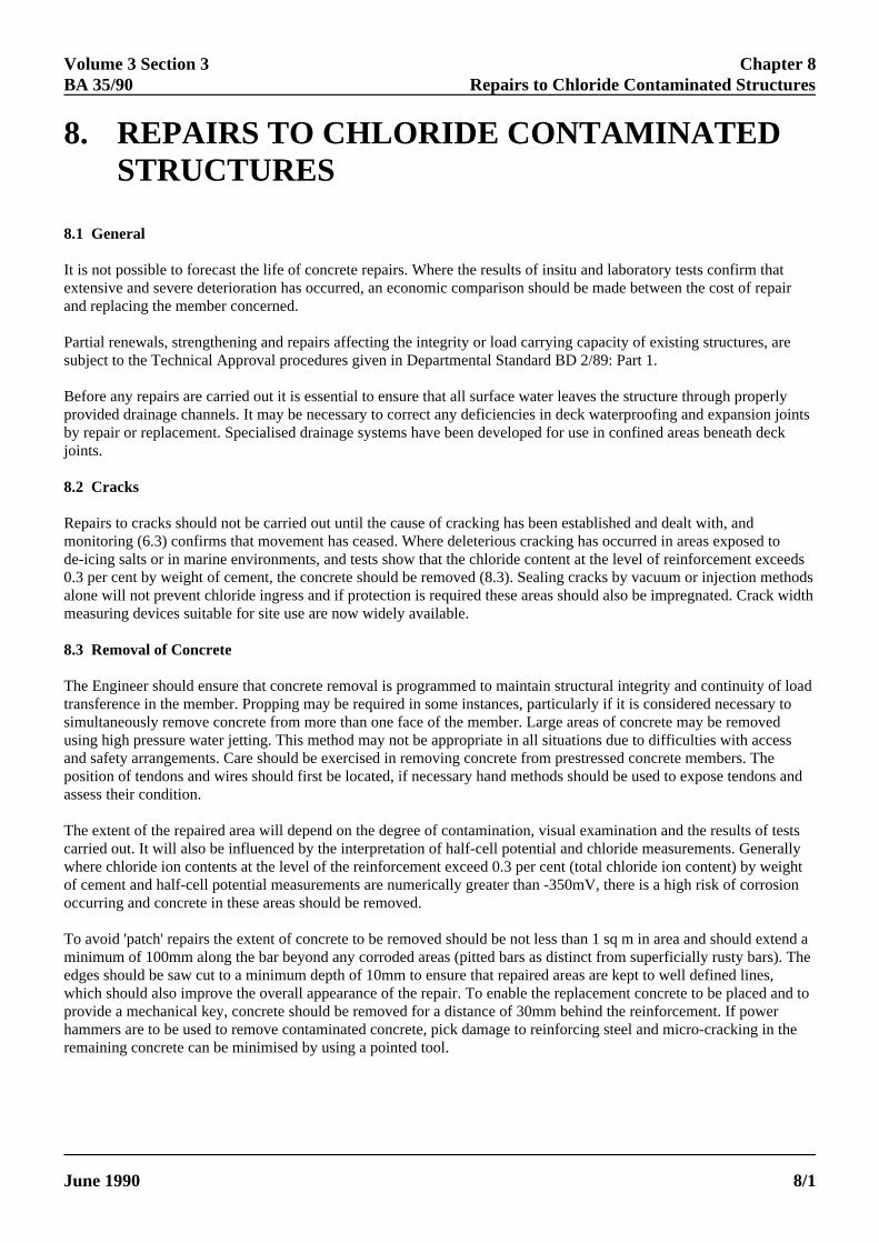
It is not possible to forecast the life of concrete repairs. Where the results of insitu and laboratory tests confirm thatextensive and severe deterioration has occurred, an economic comparison should be made between the cost of repairand replacing the member concerned.
Partial renewals, strengthening and repairs affecting the integrity or load carrying capacity of existing structures, aresubject to the Technical Approval procedures given in Departmental Standard BD 2/89: Part 1.
Before any repairs are carried out it is essential to ensure that all surface water leaves the structure through properlyprovided drainage channels. It may be necessary to correct any deficiencies in deck waterproofing and expansion jointsby repair or replacement. Specialised drainage systems have been developed for use in confined areas beneath deckjoints.
8.2 Cracks
Repairs to cracks should not be carried out until the cause of cracking has been established and dealt with, andmonitoring (6.3) confirms that movement has ceased. Where deleterious cracking has occurred in areas exposed tode-icing salts or in marine environments, and tests show that the chloride content at the level of reinforcement exceeds0.3 per cent by weight of cement, the concrete should be removed (8.3). Sealing cracks by vacuum or injection methodsalone will not prevent chloride ingress and if protection is required these areas should also be impregnated. Crack widthmeasuring devices suitable for site use are now widely available.
8.3 Removal of Concrete
The Engineer should ensure that concrete removal is programmed to maintain structural integrity and continuity of loadtransference in the member. Propping may be required in some instances, particularly if it is considered necessary tosimultaneously remove concrete from more than one face of the member. Large areas of concrete may be removedusing high pressure water jetting. This method may not be appropriate in all situations due to difficulties with accessand safety arrangements. Care should be exercised in removing concrete from prestressed concrete members. Theposition of tendons and wires should first be located, if necessary hand methods should be used to expose tendons andassess their condition.
The extent of the repaired area will depend on the degree of contamination, visual examination and the results of testscarried out. It will also be influenced by the interpretation of half-cell potential and chloride measurements. Generallywhere chloride ion contents at the level of the reinforcement exceed 0.3 per cent (total chloride ion content) by weightof cement and half-cell potential measurements are numerically greater than -350mV, there is a high risk of corrosionoccurring and concrete in these areas should be removed.
To avoid 'patch' repairs the extent of concrete to be removed should be not less than 1 sq m in area and should extend aminimum of 100mm along the bar beyond any corroded areas (pitted bars as distinct from superficially rusty bars). Theedges should be saw cut to a minimum depth of 10mm to ensure that repaired areas are kept to well defined lines,which should also improve the overall appearance of the repair. To enable the replacement concrete to be placed and toprovide a mechanical key, concrete should be removed for a distance of 30mm behind the reinforcement. If powerhammers are to be used to remove contaminated concrete, pick damage to reinforcing steel and micro-cracking in theremaining concrete can be minimised by using a pointed tool.

Chapter 8 Volume 3 Section 3Repairs to Chloride Contaminated Structures BA 35/90
ELECTRONIC COPY - NOT FOR USE OUTSIDE THE AGENCY
PAPER COPIES OF THIS ELECTRONIC DOCUMENT ARE UNCONTLED June 19908/2
8.4 Cleaning of Reinforcement
Dry methods are not effective in removing corrosion products. Where possible high pressure water jetting should beused or alternatively wet blast cleaning. Particular attention should be given to pits and crevices. Where significant lossof section has occurred or pitting is extensive, reinforcement should be replaced. Additional reinforcement may also berequired to restore serviceability if mechanical damage to reinforcement has taken place during removal of concrete.While repairs are being carried out, care should be taken to protect exposed concrete substrates and reinforcement fromsalt spray from passing traffic.
8.5 Replacement Concrete
8.5.1 General
Concreting should be programmed to minimise shrinkage cracks. Wherever practical, deficient cover to thereinforcement should be increased to meet current standards. To avoid ponding, all horizontal surfaces ie tops ofbearing shelves, piers and crossheads should be finished to a fall of 1 in 5.
Blended cement concretes properly placed and cured reduce the penetration rate of chloride ions by changing the poresize distribution and chloride binding capacity of the cement paste. They will assist in reducing the risk of chloride iondiffusing back into repaired areas. The use of bagged aggregates and cement either singly or combined offer advantagesfor small amounts of concrete mixed on site. It will also enable quality control to be maintained.
8.5.2 Water Cement Ratio and Curing
These have a profound affect on reducing permeability and increasing the durability of concrete. It is important that awater/cement ratio of 0.4 is not exceeded. All repaired areas should be continuously water cured for a minimum of 5days after placing the concrete. This can be achieved using a hose pipe 'sprinkler' system together with absorbentmaterial covered by polythene sheeting. Proprietary curing membranes do not provide a sufficient reservoir of water inthe early stages of curing and the pore blocking action of some may reduce the efficiency of subsequent impregnation.
The importance of curing to reduce shrinkage cracking and increase the durability of concrete repairs cannot be overemphasised. A separate item covering this work should be included in the Bill of Quantities.
8.5.3 Sprayed Concrete
In situations where reinforcement is not too congested sprayed concrete may be used. Care should be taken to avoidcreating 'shadow areas' behind the reinforcement. In areas that are aesthetically sensitive, the final coat should be floatfinished to provide a smooth surface. Further information is given in the Sprayed Concrete Association's Manual.Procedure trials should be carried out to demonstrate the Contractor's competence, method of working and mix design.
8.6 Minor Repairs
These include repairs to arrises and reinstatement of core holes etc.
8.7 Repair of Particular Elements
8.7.1 Crossheads
Crossheads are particularly vulnerable to chloride attack from leaking expansion joints. Where deterioration is severe itmay be necessary to provide temporary supports while repairs are carried out. This will require careful programmingand traffic management. For repairs to the sides and soffits of crossheads using high flow materials, strict control shouldbe exercised at all stages during mixing and placing of the concrete.

Volume 3 Section 3 Chapter 8BA 35/90 Repairs to Chloride Contaminated Structures
ELECTRONIC COPY - NOT FOR USE OUTSIDE THE AGENCY
June 1990 PAPER COPIES OF THIS ELECTRONIC DOCUMENT ARE UNCONTROLLED 8/3
8.7.2 Bridge Decks
Contamination of bridge decks generally occurs through failure or damage to the waterproofing membrane. Thelocation, extent and severity of the problem may only become apparent when resurfacing/waterproofing is carried out.Damp patches on the soffit while not necessarily indicating the position of faults in the membrane, can affect half-cellpotential measurements particularly on thin deck slabs. Where contamination is severe, consideration should be given toreplacing the deck slab. Where the concrete replacement option has been chosen, high pressure water jetting will reducethe risk of damage to the reinforcement. This is particularly relevant to thin deck slabs. Localised contamination atexpansion joints can occur due to inadequate sealing. All repaired areas should be continuously water cured for aminimum of 5 days after placing of the concrete, and be surface dry for a minimum of 24 hours before application ofthe waterproof membrane.

Volume 3 Section 3 Chapter 9BA 35/90 Surface Impregnation
ELECTRONIC COPY - NOT FOR USE OUTSIDE THE AGENCY
June 1990 PAPER COPIES OF THIS ELECTRONIC DOCUMENT ARE UNCONTROLLED 9/1
9. SURFACE IMPREGNATION
Concrete is not impermeable to the migration of chloride ions. It is possible that without protection, soundly constructedand properly maintained structures subjected to sustained chloride attack will eventually deteriorate during their servicelife.
Impregnation is carried out by spraying concrete surfaces with a hydrophobising material that achieves maximumpenetration of the concrete and reacts with the silicates and moisture present. This produces a water-repellant butvapour-permeable layer that inhibits the ingress of water and chloride ion. Effectiveness of this layer is determined bythe quality of the hydrophobisation and the strength and permanence of the bond between the silane molecule and thesubstrate. Impregnation is known to be effective for at least 15 years provided it is applied correctly. Longer servicelives are anticipated. However it is considered advisable to assume that re-application may be necessary after about 20years.
The depth of penetration will vary depending on concrete quality and moisture content. To obtain feedback, a recordshould be kept of the quantity of material used on treated areas and forwarded through the Regional Office to BEDivision.
After curing, the whole of repaired structural members including the tops of piers, crossheads and bearing shelvesshould be impregnated. Graffiti and encrusted surface deposits ie algae should be removed by light dry grit blasting orwire brushing. Areas with cracks not exceeding 0.3mm in width should be waterproofed by impregnation. Bridge decksurfaces which are to be waterproofed in accordance with Technical Memorandum BE 27 should not be treated. Aminimum interval of 14 days after placing the concrete is required before impregnation to allow the concrete porestructure to develop.

Volume 3 Section 3 Chapter 10BA 35/90 Draining of Voids within Bridge Decks
ELECTRONIC COPY - NOT FOR USE OUTSIDE THE AGENCY
June 1990 PAPER COPIES OF THIS ELECTRONIC DOCUMENT ARE UNCONTROLLED 10/1
10. DRAINING OF VOIDS WITHIN BRIDGEDECKS
10.1 Collection of water within the voids of bridge decks has occurred in some instances. Water finding its way into thevoids is likely to remain there unless provision has been made for drainage. It will increase the risk of corrosion of thesteel reinforcement and possibly reduce the live load carrying capacity of the bridge. Voids within existing bridge decksshould therefore be provided with drainage holes at the earliest opportunity.
10.2 Four types of non-recoverable void formers have been used in cellular or voided bridge decks:
(a) Spirally wound corrugated steel tubes.
(b) Waxed cardboard tubes and boxes.
(c) Timber.
(d) Expanded polystyrene void formers to any shape.
10.3 The following methods have been used to provide internal formwork to precast pretensioned box beams:
(a) Recoverable formwork where the concrete is cast in two stages.
(b) Recoverable, tensioned, high-tensile wire wrapped with wire netting followed by polythene sheets.
(c) Permanent formwork of hollow prefabricated box formers.
(d) Permanent formwork of expanded polystyrene.
10.4 Precast pretensioned U beams formed using collapsible steel forms and pseudo-box construction using M beamsshould both be drained.
10.5 As-built Contract Drawings should be examined to verify the method used to form the voids and the position oftendons and reinforcement. The latter should be verified by non-destructive testing before any drilling is started. Forvoided and cellular bridge decks one 22mm diameter hole should be drilled, while for precast pretensioned box, Ubeams and pseudo-box construction, two 15-20mm diameter holes should be drilled near each end on the centre line ofeach void or at the low point away from adjacent vertical concrete members using a small gauge diamond drill.
10.6 Before commencing drilling operations as-built Contract Drawings should be checked for the locations of anyStatutory Undertakers Services ie gas, water, electricity, telephone etc, and their positions confirmed on site where theyare in the vicinity of the holes to be drilled. Extreme caution should be exercised during the drilling operation to avoidcausing damage to tendons. Water held in deck voids can be highly alkaline and consequently potentially harmful.Precautions should be taken to avoid the water coming into contact with eyes or skin. If water is present in the void itshould be tested for its chloride ion content, its source of entry should be identified if possible, and measures taken toprevent further ingress into the voids. If there is any evidence of rust staining or corrosion to reinforcement thenconsideration should be given to treatment or repair of such areas.

Figure 3: DRAINING OF EXISTING VOIDED SLAB BRIDGES
22mm dia hole
Polyester Resin
UPVC Pipe with ascrew thread onoutside of barrel
13mm Nominal dia
25m
m
5mm
Detail A
Voidformer
UPVC Pipe See Detail A
Chapter 10 Volume 3 Section 3Draining of Voids within Bridge Decks BA 35/90
ELECTRONIC COPY - NOT FOR USE OUTSIDE THE AGENCY
PAPER COPIES OF THIS ELECTRONIC DOCUMENT ARE UNCONTROLLED June 199010/2
10.7 Once the holes have been drilled a 13mm nominal bore and 50mm length tube of inert material eg UPVC orsimilar with a screw thread should be fixed into the hole using a polyester resin so that it projects 25mm below the soffit(or lesser dimension where the headroom is affected), as shown in Figure 3 for a circular voided slab bridge deck.
Volume 3 Section 3 Chapter 11BA 35/90 Alkali - Silica Reaction
June 1990 PAPER COPIES OF THIS ELECTRONIC DOCUMENT ARE UNCONTROLLED 11/1
11. ALKALI - SILICA REACTION
11.1 Introduction
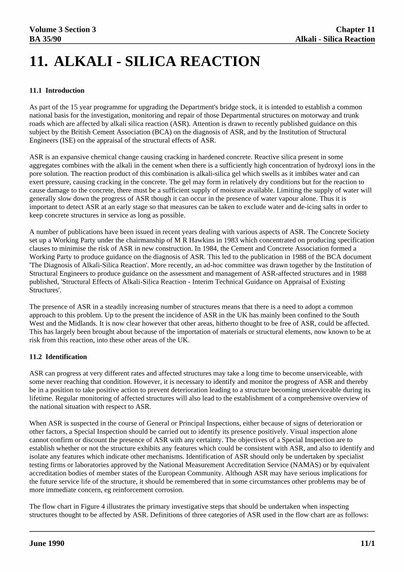
As part of the 15 year programme for upgrading the Department's bridge stock, it is intended to establish a commonnational basis for the investigation, monitoring and repair of those Departmental structures on motorway and trunkroads which are affected by alkali silica reaction (ASR). Attention is drawn to recently published guidance on thissubject by the British Cement Association (BCA) on the diagnosis of ASR, and by the Institution of StructuralEngineers (ISE) on the appraisal of the structural effects of ASR.
ASR is an expansive chemical change causing cracking in hardened concrete. Reactive silica present in someaggregates combines with the alkali in the cement when there is a sufficiently high concentration of hydroxyl ions in thepore solution. The reaction product of this combination is alkali-silica gel which swells as it imbibes water and canexert pressure, causing cracking in the concrete. The gel may form in relatively dry conditions but for the reaction tocause damage to the concrete, there must be a sufficient supply of moisture available. Limiting the supply of water willgenerally slow down the progress of ASR though it can occur in the presence of water vapour alone. Thus it isimportant to detect ASR at an early stage so that measures can be taken to exclude water and de-icing salts in order tokeep concrete structures in service as long as possible.
A number of publications have been issued in recent years dealing with various aspects of ASR. The Concrete Societyset up a Working Party under the chairmanship of M R Hawkins in 1983 which concentrated on producing specificationclauses to minimise the risk of ASR in new construction. In 1984, the Cement and Concrete Association formed aWorking Party to produce guidance on the diagnosis of ASR. This led to the publication in 1988 of the BCA document'The Diagnosis of Alkali-Silica Reaction'. More recently, an ad-hoc committee was drawn together by the Institution ofStructural Engineers to produce guidance on the assessment and management of ASR-affected structures and in 1988published, 'Structural Effects of Alkali-Silica Reaction - Interim Technical Guidance on Appraisal of ExistingStructures'.
The presence of ASR in a steadily increasing number of structures means that there is a need to adopt a commonapproach to this problem. Up to the present the incidence of ASR in the UK has mainly been confined to the SouthWest and the Midlands. It is now clear however that other areas, hitherto thought to be free of ASR, could be affected.This has largely been brought about because of the importation of materials or structural elements, now known to be atrisk from this reaction, into these other areas of the UK.
11.2 Identification
ASR can progress at very different rates and affected structures may take a long time to become unserviceable, withsome never reaching that condition. However, it is necessary to identify and monitor the progress of ASR and therebybe in a position to take positive action to prevent deterioration leading to a structure becoming unserviceable during itslifetime. Regular monitoring of affected structures will also lead to the establishment of a comprehensive overview ofthe national situation with respect to ASR.
When ASR is suspected in the course of General or Principal Inspections, either because of signs of deterioration orother factors, a Special Inspection should be carried out to identify its presence positively. Visual inspection alonecannot confirm or discount the presence of ASR with any certainty. The objectives of a Special Inspection are toestablish whether or not the structure exhibits any features which could be consistent with ASR, and also to identify andisolate any features which indicate other mechanisms. Identification of ASR should only be undertaken by specialisttesting firms or laboratories approved by the National Measurement Accreditation Service (NAMAS) or by equivalentaccreditation bodies of member states of the European Community. Although ASR may have serious implications forthe future service life of the structure, it should be remembered that in some circumstances other problems may be ofmore immediate concern, eg reinforcement corrosion.
The flow chart in Figure 4 illustrates the primary investigative steps that should be undertaken when inspectingstructures thought to be affected by ASR. Definitions of three categories of ASR used in the flow chart are as follows:

Chapter 11 Volume 3 Section 3Alkali - Silica Reaction BA 35/90
ELECTRONIC COPY - NOT FOR USE OUTSIDE THE AGENCY
PAPER COPIES OF THIS ELECTRONIC DOCUMENT ARE UNCONTROLLED June 199011/2
Suspect - structures which are suspected to be suffering from ASR due to the presence of map-type cracking and/orother factors eg structures categorised as 'potential'.
Confirmed - structures where laboratory tests have confirmed the presence of ASR.
Potential - structures with similar aggregates/alkali contents to structures where ASR has been confirmed.
The BCA document describes the various steps to be undertaken during this process which can lead to the identificationof ASR as the primary cause of deterioration or eliminate it from further consideration.
11.3 Management and Monitoring of Structures Affected by ASR
When ASR is confirmed records of other structures in the vicinity should be examined, especially of those constructedin the same contract, to check whether or not the same aggregate and cement were used. If records are not available theaggregate can be identified from cores 50mm diameter by 100mm long. The choice of structures to be examined isdetermined by the number of different contracts, known geology of aggregate sources in the areas, known local cementalkali contents (at the time of construction if possible), and the number of structures in each contract. Where aggregatesare identified as potentially reactive, structures should be observed for signs of ASR in the course of General orPrincipal Inspections and Special Inspections should follow if considered necessary. The identification of aggregatessusceptible to ASR and the results of these investigations are important records for future investigatory work and shouldbe included in the Special Inspection Report. A revised copy of BE 13 should be forwarded for amendment of theBridge Database.
The need for a structural assessment should be considered if ASR is confirmed. The effects of ASR on the ultimatestrength of reinforced concrete is still a subject for research but vulnerable details can be identified. Tests on concretesamples have indicated that ASR-affected concrete generally has a high cube crushing strength for uncracked cores buthas a markedly reduced tensile strength as a result of the development of micro-cracking and internal stresses. Theexpansion of ASR-affected concrete is restrained by reinforcement which sets up stresses and strains in the concretesuperimposed upon the structural effects. Details sensitive to the effects of ASR should be carefully noted. Theseinclude half-joints, pile caps, zones of high bond stress and concrete elements with little or no shear steel. Furtherguidance on the effects of ASR on concrete structures is given in the ISE report.
Where ASR has been positively identified, the long-term programme for the management of structures should also bereviewed. The current expansion should be determined by measurement of the crack widths especially at structurallysensitive locations. If possible, overall structural dimensions should also be monitored. The potential for expansionshould be estimated from expansion testing of cores. For rapid diagnosis, the expansion testing is normally carried outat 38°C and 100% RH, but there is increasing evidence that over the longer term, lower temperatures will lead to greaterexpansion levels. The testing of cores for longer periods at lower temperatures should therefore be considered in termsof the structural importance of the element being investigated.
The ISE report suggests generalised guidelines for the management and the monitoring procedures for concretestructures suffering from ASR. It describes the relationship that exists between the site environment, the reinforcementdetailing, an expansion index - determined from the current and total

In the course of General or Principal Inspections(ref. TRMM 2/88) structure is suspected to beaffected by ASR because of pattern of cracking,surface deposits and/or other factors.
Class the structure as 'Suspect'.
Does the geology of aggregate sources and alkali content in the concrete mix suggest the possibility of ASR? Obtain information from construction records and cores.
Carry out Special Inspection to establish whether structure exhibits any features which are consistent with ASR and to determine whether or not ASR is present. Investigation should include determining from cores the alkali contents/aggregate types for different mixes, petrographic examination, accelerated expansion tests and evaluating environmental conditions.
Do results indicate ASR is primary cause of deterioration?
Structure is classed as 'Confirmed' Examine records of other structures in the contract
or where similar aggregates and cements have been used. Structures in this category are classed as 'Potential' and should be kept under observation in the course of General or Principal Inspections. Special Inspections may also be necessary.
Is the degree and extent of cracking severe enough to warrant an assessment?
Insert frequency of inspection or provideregular monitoring arrangements.
Carry out structural assessment.
Investigate for otherforms of deterioration.
YES
NO
NO
YES
NO
YES
PRIMARY INVESTIGATIVE STEPS THAT SHOULD BE UNDERTAKEN WHENINSPECTING STRUCTURES LIKELY TO BE AFFECTED BY ASR.
Figure 4 :
Volume 3 Section 3 Chapter 11BA 35/90 Alkali - Silica Reaction
ELECTRONIC COPY - NOT FOR USE OUTSIDE THE AGENCY
June 1990 PAPER COPIES OF THIS ELECTRONIC DOCUMENT ARE UNCONTROLLED 11/3
Chapter 11 Volume 3 Section 3Alkali - Silica Reaction BA 35/90
ELECTRONIC COPY - NOT FOR USE OUTSIDE THE AGENCY
PAPER COPIES OF THIS ELECTRONIC DOCUMENT ARE UNCONTROLLED June 199011/4
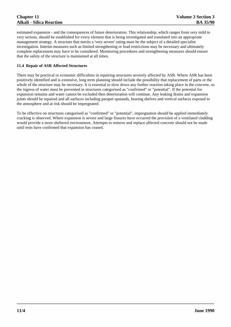
estimated expansion - and the consequences of future deterioration. This relationship, which ranges from very mild tovery serious, should be established for every element that is being investigated and translated into an appropriatemanagement strategy. A structure that merits a 'very severe' rating must be the subject of a detailed specialistinvestigation. Interim measures such as limited strengthening or load restrictions may be necessary and ultimatelycomplete replacement may have to be considered. Monitoring procedures and strengthening measures should ensurethat the safety of the structure is maintained at all times.
11.4 Repair of ASR Affected Structures
There may be practical or economic difficulties in repairing structures severely affected by ASR. Where ASR has beenpositively identified and is extensive, long term planning should include the possibility that replacement of parts or thewhole of the structure may be necessary. It is essential to slow down any further reaction taking place in the concrete, sothe ingress of water must be prevented in structures categorised as "confirmed" or "potential". If the potential forexpansion remains and water cannot be excluded then deterioration will continue. Any leaking drains and expansionjoints should be repaired and all surfaces including parapet upstands, bearing shelves and vertical surfaces exposed tothe atmosphere and at risk should be impregnated.
To be effective on structures categorised as "confirmed" or "potential", impregnation should be applied immediatelycracking is observed. Where expansion is severe and large fissures have occurred the provision of a ventilated claddingwould provide a more sheltered environment. Attempts to remove and replace affected concrete should not be madeuntil tests have confirmed that expansion has ceased.

Volume 3 Section 3 Chapter 12BA 35/90 References
ELECTRONIC COPY - NOT FOR USE OUTSIDE THE AGENCY
June 1990 PAPER COPIES OF THIS ELECTRONIC DOCUMENT ARE UNCONTROLLED 12/1
12. REFERENCES
Departmental and HMSO Publications
1. Bridge Inspection Guide (HMSO) 1983.
2. Trunk Road Management and Maintenance Notice TRMM 2/88, Trunk Road and Motorway Structures - Recordsand Inspection.
3. Technical Memorandum BE 27, Waterproofing and Surfacing of Bridge Decks.
4. Departmental Standard BD 2/89: Part 1 , Technical Approval of Highway Structures on Motorways and other TrunkRoads.
5. Departmental Standard, BD 43/90, Criteria and Material for the Impregnation of Concrete Highway Structures.
6. Departmental Advice Note BA 33/90, Impregnation of Concrete Highway Structures.
7. The Performance of Concrete in Bridges (HMSO), April 1989.
British Standards (Published by BSI)
8. BS 1881: Methods of Testing Concrete
Part 5: 1970 Methods of testing hardened concrete for other than strength
Analysis of hardened concrete
Part 105: 1984 Method for determination of flow
Part 108: 1983 Method of making test cubes from fresh concrete
Part 111: 1983 Method of normal curing of test specimens
Part 116: 1983 Method for determination of compressive strength of concrete cubes
Part 120: 1983 Method for determination of the compressive strength of concrete cores
Part 201: 1986 Guide to the use of non-destructive methods of test for hardened concrete
Part 202: 1986 Recommendations for surface hardness testing by rebound hammer
Part 203: 1986 Measurement of the velocity of ultrasonic pulses in concrete
Part 204: 1988 Recommendations on the use of electromagnetic covermeters
9. BS 4551: 1980 Methods of testing mortars screeds and plasters.
10. BS 5400: Steel, concrete and composite bridgesPart 4: 1984 Code of practice for design of concrete bridges

Chapter 12 Volume 3 Section 3References BA 35/90
ELECTRONIC COPY - NOT FOR USE OUTSIDE THE AGENCY
PAPER COPIES OF THIS ELECTRONIC DOCUMENT ARE UNCONTROLLED June 199012/2
American Society for Testing Materials (Published by ASTM)
11. ASTM C876 Method for Half-Cell Potentials of Uncoated Reinforcing Steel in Concrete.
Transport and Road Research Laboratory Publications
12. LR 953: A survey of site tests for the assessment of corrosion in reinforced concrete. P R Vassie
13. LR 981: Case studies of the corrosion of reinforcement in concrete structures. R J Woodward.
14. AG3: Microprocessor controlled multiple half-cell measurements. M A Winnett.
15. RR 81: Repair of cracked concrete: assessment of injection methods. A J Calder.
16. RR 150: Repair of cracked concrete: assessment of corrosion protection. A J Calder and D M Thompson.
17. RR 109: Durability of concrete repairs: the effect of steel cleaning procedures. P R Vassie.
18. The half-cell method of locating corroding reinforcement in concrete structures. Application Guide 9. P R Vassie.
Building Research Establishment Publications
19. CP 25/77: A simple pull out test to assess the strength of in-situ concrete.
20. IP 21/86: Determination of chloride and cement of hardened concrete.
Other References
21 The Diagnosis of Alkali-Silica Reaction. Report of a working party, British Cement Association, 1988.
22. Structural effects of Alkali-Silica Reaction - Interim technical guidance on appraisal of existing structures. TheInstitution of Structural Engineers, 1988.
Volume 3 Section 3 Chapter 13BA 35/90 Enquiries
ELECTRONIC COPY - NOT FOR USE OUTSIDE THE AGENCY
June 1990 PAPER COPIES OF THIS ELECTRONIC DOCUMENT ARE UNCONTROLLED 13/1
All enquiries or comments about this Advice Note should be sent in writing to:
Head of DivisionBridges Engineering DivisionDepartment of TransportSt Christopher HouseSouthwark StreetLONDON SE1 0TE Quoting Reference : BE 28/14/021
Orders for furthur copies of this Advice Note should be accompanied by the remittance shown on the cover andaddressed to :-
DOE / DTp Publications Sales UnitBuilding OneVictoria RoadSouth RuislipMiddlesexHA4 0NZTelephone No : 081-841-3425
13. ENQUIRIES
P H DAWEHead of Bridges Engineering DivisionDepartment of TransportSt Christopher HouseSouthwark StreetLONDON SE1 0TE
June 1990