inspection and evaluation of concrete in 1913 facilities
TRANSCRIPT

www.CTLGroup.com
Corporate Office: 5400 Old Orchard Road Skokie, Illinois 60077-1030 Phone: 847-965-7500 Fax: 847-965-6541 Washington D.C. Office: 9030 Red Branch Road, Suite 110 Columbia, Maryland 21045-2003 Phone: 410-997-0400 Fax: 410-997-8480
CTLGroup is a registered d/b/a of Construction Technology Laboratories, Inc.
Inspection and Evaluation of Concrete in 1913 Facilities, Evanston, Illinois
Report to City of Evanston Water and Sewer Division 555 Lincoln Street Evanston, IL 60201 by John J. Roller, PE, SE Carlton A. Olson February 26, 2010 CTLGroup Project No. 262442 COA # 184-001246

Inspection and Evaluation of Concrete in 1913 Facilities Page i of ii CTLGroup Project No. 262442 February 26, 2010
www.CTLGroup.com
TABLE OF CONTENTS
Page
1 INTRODUCTION ...................................................................................................................1
2 REVIEW OF AVAILABLE DOCUMENTS ..............................................................................3
3 FIELD INVESTIGATION........................................................................................................3
3.1 INSPECTION OF FILTER TANKS ................................................................................3
3.1.1 Visual Inspection and Hammer Sounding of Filter Tank Concrete Surfaces ............4
3.1.2 Nondestructive Testing (NDT) of Filter Tank Concrete .............................................9
3.2 INSPECTION OF CLEARWELLS 1 AND 2.................................................................11
3.2.1 Visual Inspection and Hammer Sounding of Clearwell Concrete Surfaces.............12
3.2.2 Nondestructive Testing (NDT) of Clearwell Concrete .............................................14
3.3 INSPECTION OF PIPE GALLERY AND DEHUMIDIFICATION ROOM .....................16
4 SAMPLING, TESTING AND EXAMINATION OF CONCRETE ...........................................19
4.1 Concrete Compressive Strength Results ....................................................................20
4.2 Concrete Chloride Testing Results..............................................................................21
4.3 Microscopic (Petrographic) Examination Results........................................................22
4.3.1 Core Sample F15 ....................................................................................................22
4.3.2 Core Sample C7......................................................................................................23
5 DISCUSSION OF FINDINGS AND CONCEPTUAL REPAIR RECOMMENDATIONS........24
5.1 FILTER TANK ROOF SLABS .....................................................................................24
5.2 FILTER TANK BACK WALLS .....................................................................................25

Inspection and Evaluation of Concrete in 1913 Facilities Page ii of ii CTLGroup Project No. 262442 February 26, 2010
www.CTLGroup.com
5.3 FILTER TANK SIDE WALLS.......................................................................................26
5.4 CLEARWELL WALLS AND CEILING .........................................................................26
5.5 MISCELLANEOUS REPAIRS IN FILTERS AND PIPE GALLERY .............................28
5.6 PRELIMINARY COST DATA FOR CONCEPTUAL REPAIRS....................................28
Inspection and Evaluation of Concrete in 1913 Facilities Page 1 of 29 CTLGroup Project No. 262442 February 26, 2010
www.CTLGroup.com
INSPECTION AND EVALUATION OF CONCRETE IN 1913 FACILITIES
by
John J. Roller, P.E., S.E. 1
Carlton A. Olson 2
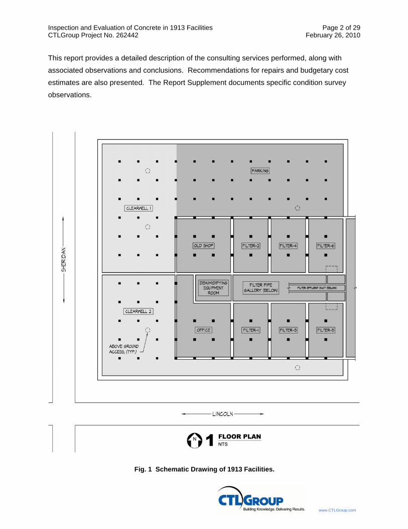
1 INTRODUCTION
The City of Evanston operates a water treatment facility located at 555 Lincoln Street in
Evanston, Illinois. The original portion of this facility (the West Plant) was constructed in 1913.
The 1913 facilities include six filter tanks (Filters 1 through 6), two below-grade filtered water
reservoirs (Clearwells 1 and 2), a pipe gallery, and dehumidification equipment room. A
schematic drawing identifying the locations of the 1913 facilities is shown in Fig. 1. CTLGroup
was retained by the City of Evanston to perform inspection and evaluation of the concrete
incorporated in the 1913 facilities. The scope of the inspection and evaluation program included
the following:
• Review of available documents.
• Visual inspection and limited nondestructive testing of Filters 1 through 6.
• Visual inspection of pipe gallery and dehumidification room areas.
• Visual inspection and limited nondestructive testing of Clearwells 1 and 2.
• Extraction of concrete core samples from selected areas of filters and clearwell structures.
• Laboratory testing and examination of extracted concrete core samples.
• Preparation of a written report.
1 Principal Structural Engineer, CTLGroup, 5400 Old Orchard Road, Skokie, IL 60077 2 Principal and Group Manager, CTLGroup, 5400 Old Orchard Road, Skokie, IL 60077
Inspection and Evaluation of Concrete in 1913 Facilities Page 2 of 29 CTLGroup Project No. 262442 February 26, 2010
www.CTLGroup.com
This report provides a detailed description of the consulting services performed, along with
associated observations and conclusions. Recommendations for repairs and budgetary cost
estimates are also presented. The Report Supplement documents specific condition survey
observations.
Fig. 1 Schematic Drawing of 1913 Facilities.
Inspection and Evaluation of Concrete in 1913 Facilities Page 3 of 29 CTLGroup Project No. 262442 February 26, 2010
www.CTLGroup.com
2 REVIEW OF AVAILABLE DOCUMENTS
CTLGroup reviewed available drawings related to the 1913 facilities. These drawings were
identified as “1915 Mechanical Record Plans,” and incorporated construction details related to
the filtered water reservoirs (clearwells), the pipe gallery (including the dehumidification
equipment room), and filter tanks. Drawings reviewed by CTLGroup included Sheets 1 through
20 of these plans.
CTLGroup also reviewed information related to chemical use history at the water treatment
plant. Historical chemical use data was provided by Mr. Kevin Lookis in an e-mail dated
January 4, 2010. Chemical compounds containing chlorides or sulfates can be detrimental to
concrete or embedded steel reinforcement if concentrations are high enough. Based on the
information provided, it is apparent that aluminum sulfate (either alone or in combination with
cationic polymer) and chlorine gas have been used for decades at the Evanston plant.
Treatment practices employed at the Evanston plant are reportedly consistent with other
Chicago-Area water treatment facilities that draw water from Lake Michigan. Testing and
examination of concrete core samples extracted from interior surfaces of clearwell and filter
structures were performed during this program to evaluate significance of chemical exposure
that has occurred to date.
3 FIELD INVESTIGATION
3.1 INSPECTION OF FILTER TANKS
The 1913 facilities include six filter tanks (Filters 1 through 6). According to available drawings,
each filter has exterior plan dimensions of 25 ft x 38 ft. The 38-ft long concrete side walls are 9-
in. thick, and are reinforced with a single layer of vertical and horizontal bars located near the
outer face. The 25-ft long concrete end walls are predominantly 12-in. thick; however, the
above-grade portion of the exterior end wall tapers from 12- to 9-in. thick within the upper 3 ft
region. The interior end wall is reinforced with a single layer of vertical and horizontal bars
located near the outer face. The exterior end wall is reinforced with two layers of vertical and
horizontal bars.
The overall depth of each filter tank is 10 ft, with the lower 3.5 feet occupied by the strainer
system and filtration media. Each filter tank is longitudinally divided into halves (east and west)
by a central 2 ft wide channel that collects wash water from a network of six gutters located on
each side. The interior concrete walls that form the sides of the channel are 6-in. thick and are

Inspection and Evaluation of Concrete in 1913 Facilities Page 4 of 29 CTLGroup Project No. 262442 February 26, 2010
www.CTLGroup.com
reinforced with two layers of vertical and horizontal bars. Both channel walls have a series of
four equally-spaced large window openings near the top separated by three 18-in. wide
columns.
Each filter tank has a concrete roof slab that covers approximately 75% of the plan area. The
roof originally consisted of a 5-in.-thick concrete slab reinforced with a single layer of bars in
both longitudinal and transverse directions. Since the time of original construction, the top
surface of the roof slab of all six filter tanks has reportedly been subject to multiple
repair/rehabilitation programs. The top surface of the roof slab for Filters 1 through 6 has
reportedly undergone at least one partial-depth repair, and the addition of a supplementary
lightweight topping layer. Approximately eight years ago, a 6-ft wide strip of the lightweight
topping along the outermost edge of the roof slab for Filters 1, 3 and 5 was reportedly removed
and replaced. The roof slab for Filters 2, 4 and 6 reportedly underwent a partial-depth repair
approximately two years ago (2008) wherein the lightweight topping and the upper portion of the
slab was demolished and replaced with new concrete.
The top surface of the roof slab and the exterior above-grade portion of the south wall of Filters
1, 3 and 5 are currently exposed to weather. The top surface of the roof slab for Filters 2, 4 and
6 was recently enclosed, leaving only the exterior above-grade portion of the north wall exposed
to weather. All other filter tank wall, floor, or roof surfaces are either below grade or within the
building enclosure.
On January 12 through 14, 2010, CTLGroup performed visual inspection, hammer sounding,
and limited nondestructive testing of accessible concrete surfaces of Filters 1 through 6.
Concrete core samples were also extracted at various locations.
3.1.1 Visual Inspection and Hammer Sounding of Filter Tank Concrete Surfaces
On the interior of each filter, all wall surfaces above the filter media and the bottom surface of
the roof slab were visually examined and sounded. On the exterior, the top surface of the roof
slab and above-grade portion of the north (Filter Nos. 2, 4 and 6) or south (Filter Nos. 1, 3 and
5) walls were visually examined and sounded. Sounding involves striking the concrete surface
with a hammer and listening for audible indications of distress. Sound, undamaged concrete
will typically exhibit a distinct ring or “sharp” audible sound that is consistent with what would be
expected from impact with a hard steel tool. Concrete that has been altered or damaged will
typically exhibit an audible sound that is “dull” or hollow-sounding when struck with a metallic

Inspection and Evaluation of Concrete in 1913 Facilities Page 5 of 29 CTLGroup Project No. 262442 February 26, 2010
www.CTLGroup.com
object. Observed concrete cracks and areas where hammer sounding revealed audible
indications of suspect integrity were mapped to scale on drawings. Maximum crack widths were
measured and documented where possible. Documented observations for each of the filter
tanks are provided in the Report Supplement (see F-Series sheet numbers). Significant findings
from the filter tank inspections are as follows:
1. All original interior concrete wall surfaces exhibited varying degrees of surface scaling.
2. The interior surface of the back wall exhibited ice build-up, indicating that both interior and
exterior surfaces of these walls are subject to freeze-thaw exposure during winter months.
3. Interior inspection of each filter tank revealed that a 1-to-2-in. thick layer of shotcrete has
been applied to the underside of the roof slab. It is our understanding that this shotcrete
was likely applied sometime in the 1980’s. The shotcrete layer typically extends down the
adjoining vertical walls for a distance of approximately 12 in. Varying degrees of cracking
was observed in the shotcrete layer for all six filter tanks. Cracks in the shotcrete are filled
with efflorescence (a white-colored deposit), thus preventing crack width measurement.
Localized delaminated/hollow-sounding areas were noted in five of the six filters, with
Filters 2, 4 and 6 exhibiting the greatest populations of these areas. Evidence of shotcrete
repair was also observed in these three filters. Exposed/corroded wire mesh
reinforcement was noted in the shotcrete layer for Filters 2, 3 and 5. Specific locations of
cracks and delaminated/hollow-sounding areas are shown in the reflected ceiling plans
included in the Report Supplement.
4. The west side wall of Filters 1 and 3 exhibits a horizontal crack on the interior surface.
Both cracks are very similar in location and appearance. These cracks appear to initiate at
the inside corner where the west wall intersects the back wall, and extend for a length of
approximately 25 to 28 ft. Both cracks have been repaired (filled) over a portion of the
length using a black tar-like substance, and then subsequently covered with a thin layer of
shotcrete. Where unfilled, estimates of crack widths range from 0.020 to 0.040 in. The
thin shotcrete layer has become loose or fallen off at several locations. A photograph of
the crack noted in the west side wall of Filter 2 is shown in Fig. 2.

Inspection and Evaluation of Concrete in 1913 Facilities Page 6 of 29 CTLGroup Project No. 262442 February 26, 2010
www.CTLGroup.com
Fig. 2 Crack Noted in West Side Wall of Filter 2.
5. The side walls of all six filters typically exhibit one or more vertical or diagonal cracks that
generally extend from the roof slab down below the filter media. In many instances, these
cracks coincide with gutter locations. Most cracks are filled with efflorescence, thus
preventing crack width measurement. Where unfilled, estimates of crack widths range
from 0.015 to 0.025 in. A photograph of the cracks noted in the west side wall of Filter 6 is
shown in Fig. 3.
6. The interior surface of the back wall of all six filters typically exhibits multiple cracks.
These cracks are generally horizontal or diagonal. Many of the cracks intersect the interior
concrete walls that form the sides of the channel that bisects each filter tank. Most cracks
are filled with efflorescence, thus preventing crack width measurement. Where unfilled,
estimates of crack widths range from 0.015 to 0.025 in. The back wall for two of the six
filters (Filters 2 and 4) exhibited localized areas near the roof slab where hammer
sounding revealed audible indications of suspect integrity. A photograph of the cracks
noted in the back wall of Filter 2 is shown in Fig. 4.

Inspection and Evaluation of Concrete in 1913 Facilities Page 7 of 29 CTLGroup Project No. 262442 February 26, 2010
www.CTLGroup.com
Fig. 3 Cracks Noted in West Side Wall of Filter 6.
Fig. 4 Cracks Noted in Back Wall of Filter 2.

Inspection and Evaluation of Concrete in 1913 Facilities Page 8 of 29 CTLGroup Project No. 262442 February 26, 2010
www.CTLGroup.com
7. Wash water gutters appear to be in good condition, exhibiting no visible cracking except at
wall interfaces.
8. Localized areas exhibiting delaminated/hollow sounding and/or cracked concrete were
observed at a few locations near the interior openings of the filter tanks. These areas were
generally limited to the underside of the short elevated slab section that spans
longitudinally between the front end wall and roof slab, and to the innermost edge of the
roof slab. In some instances, previous repair attempt was evident. An example of such
distress is shown in Fig. 5.
9. Exterior above-grade portions of the back wall of all six filter tanks typically exhibit a
uniform network of fine cracks likely caused by freeze-thaw exposure. A photograph of
this typical cracking is shown in Fig. 6. All cracks are filled with efflorescence, thus
preventing crack width measurement. Several areas where hammer sounding revealed
audible indications of suspect integrity were also noted on the exterior surface of these
walls.
Fig. 5 Distress Noted at Interior Opening of Filter 3.

Inspection and Evaluation of Concrete in 1913 Facilities Page 9 of 29 CTLGroup Project No. 262442 February 26, 2010
www.CTLGroup.com
Fig. 6 Typical Cracking Noted on South Wall Exterior Surface of Filter 5.
10. The exterior roof surface for Filters 1, 3 and 5 exhibits several large delaminated/hollow-
sounding areas within portions incorporating the lightweight topping. Most of these hollow-
sounding areas are adjacent to the manhole openings that penetrate the roof slab. Other
areas not incorporating the lightweight topping (the 6-ft wide strip incorporating
conventional concrete topping along the outermost edge of the roof) exhibit a network of
fine, orthogonal, regularly-spaced cracks.
11. The top roof surface for Filters 2, 4 and 6 exhibits a somewhat uniform network of random
cracks. Most cracks intersect the manhole openings that penetrate the roof slab.
3.1.2 Nondestructive Testing (NDT) of Filter Tank Concrete
Nondestructive testing (NDT) using pachometer and Impulse Response (IR) equipment was
performed in representative study areas. A pachometer is an instrument that utilizes an
electromagnetic field to locate steel elements embedded in concrete. Pachometer surveys were
performed on the north wall of Filter 4 and the south wall of Filter 3 to identify reinforcing bar
spacing and concrete cover. One representative area was selected and tested on both interior
and exterior wall surfaces of each filter. Surveys were performed within the upper tapered

Inspection and Evaluation of Concrete in 1913 Facilities Page 10 of 29 CTLGroup Project No. 262442 February 26, 2010
www.CTLGroup.com
portion of the wall where thickness decreases from 12 in. to 9 in. According to available
drawings, the specified wall reinforcement consists of two layers of vertical (5/8” @ 24 in.) and
horizontal (3/8” @ 18 in.) bars. Results from the pachometer surveys indicated spacing of
reinforcement was reasonably consistent with what was specified in available drawings.
Measured concrete cover over the reinforcing bars varied considerably, ranging from as little as
3/8” to as much as 2-3/4”. Concrete cover requirements are not specified in the drawings.
Current code requirements for cast-in-place concrete exposed to weather call for minimum
concrete cover of 1-1/2 in.
The IR NDT technique involves applying a low strain impact to the concrete surface with a
hammer of a known mass, and measuring the force input and velocity response. The principal
output parameter yielded from IR testing is average mobility. The average mobility is defined as
the surface velocity responding to the impact divided by the force input [(m/s)/N x10–7]. The
mean mobility value over the 0.1-1 kHz range is directly related to the concrete modulus,
density and effective thickness. In general, presence of an internal delaminated layer,
weakened layer or cold joint, will result in an increased average mobility value. On the other
hand, a sound concrete element without distress will typically exhibit a reduced average mobility
value.
IR surveys were performed on the interior surface of the south wall of Filter 3, and on the
exterior surface of the north wall of Filter 4. As indicated by the condition survey results
provided on pages F3-D and F4-E of the Report Supplement, the south wall of Filter 3 and north
wall of Filter 4 exhibited multiple areas of concrete distress in the form of cracking and/or
audible indications of suspect integrity. For comparison, an IR survey was also performed on
the interior surface of the east wall of Filter 3, in an area where there is no evidence of concrete
distress. Results from the IR surveys indicated correlation between observed surface
conditions and corresponding average mobility readings. Average mobility readings obtained
from the east wall of Filter 3 were consistent and relatively low, indicating that the wall is sound
in the area where the survey was performed. Average mobility readings for the interior surface
of the south wall of Filter 3 and exterior surface of the north wall of Filter 4 were generally higher
and more variable, indicating the integrity of these walls has likely been compromised to various
extents due to deterioration.
In an effort to confirm the results from the IR testing, concrete cores were extracted from
selected locations within the IR survey areas. Locations of the concrete cores are identified in

Inspection and Evaluation of Concrete in 1913 Facilities Page 11 of 29 CTLGroup Project No. 262442 February 26, 2010
www.CTLGroup.com
condition survey documentation given in the Report Supplement. Results from the IR testing
are provided in Table 1, along with corresponding observations documented before and after
core extraction. Photographs of the extracted cores are provided in Appendix A.
Table 1 – IR NDT Test Results and Corresponding Core Observations
Filter Test/Core Location
Concrete Surface
Condition
Average Mobility, (m/s)/N x10–7
Core I.D. Core Condition Observation
3 East Wall,
Interior Surface
No Cracks/ Sound
6.33 F3 No Cracks
3 South Wall,
Interior Surface
Cracked/ Sound 23.10 F1
Transverse cracking noted at depth of 1-1/2 in. from
surface.
3 South Wall,
Interior Surface
Cracked/ Sound 19.25 F2
Transverse cracking noted at depths of 2-1/2 in., 3-1/2 in. and 5-1/4 in. from surface.
4 North Wall,
Exterior Surface
No Cracks/ Sound
5.64 F12 No Cracks
4 North Wall,
Exterior Surface
Cracked/ Hollow 56.72 F13
Multiple transverse cracks noted within 4-1/2 in. from
surface.
4 North Wall,
Exterior Surface
Cracked/ Dull 12.54 F14 Horizontal crack noted
through full length of core.
3.2 INSPECTION OF CLEARWELLS 1 AND 2
The 1913 facilities include two filtered water reservoirs (Clearwells 1 and 2). The two clearwells
are located entirely below grade, and a portion of each supports the building that houses the six
filter tanks. According to available drawings, the northernmost clearwell (Clearwell No. 1) is
rectangular-shaped and has interior plan dimensions of approximately 87 ft x 161 ft. The
southernmost clearwell (Clearwell No. 2) is L-shaped with maximum interior plan dimensions of
approximately 67 ft x 161 ft. Both clearwells have curved (elliptical) floor and ceiling surfaces,
and floor-to-ceiling heights ranging from approximately 14 to 19 ft. The clearwell ceiling slabs
are supported by 16 in. x 16 in. or 20 in. x 20 in. concrete square columns spaced at 12.5 ft on
center. The ceiling slab thickness is 9 in. beneath the building and 6 in. elsewhere. The
exterior walls range from 18 to 36-in. thick.

Inspection and Evaluation of Concrete in 1913 Facilities Page 12 of 29 CTLGroup Project No. 262442 February 26, 2010
www.CTLGroup.com
On January 21 through 25, 2010, CTLGroup performed visual inspection, sounding, and limited
nondestructive testing of accessible concrete surfaces of Clearwells 1 and 2. Concrete core
samples were also extracted at various locations.
3.2.1 Visual Inspection and Hammer Sounding of Clearwell Concrete Surfaces
On the interior of each clearwell, all wall, floor, column, and ceiling surfaces were visually
examined. On the interior of Clearwell 1, sounding of accessible wall, floor, column, and ceiling
surfaces was also performed. Observed concrete cracks and areas where hammer sounding
revealed audible indications of suspect integrity were mapped to scale on drawings. Maximum
crack widths were measured and documented where possible. Documented observations for
each of the clearwells are provided in the Report Supplement (see CW-Series sheet numbers).
Significant findings from the clearwell inspections are as follows:
1. All interior concrete wall and column surfaces exhibited varying degrees of surface
scaling. Observed scaling was noticeably more extensive in Clearwell 1 than in
Clearwell 2.
2. Approximately 25 percent of the plan area for Clearwell 1 and 50 percent of the plan
area for Clearwell 2 serves as the foundation for the building above. After draining each
clearwell, frost was observed on portions of the ceiling not directly below the building.
Based on this observation, it appears that portions of the roof slab for both clearwells
may be subject to freeze-thaw exposure during winter months. In addition, it was noted
that approximately 35 percent of the plan area for Clearwell 1 lies directly beneath a
paved area that accommodates parking and access to a loading dock. Consequently, it
appears that a portion of the roof slab for Clearwell 1 may also be exposed to de-icing
salts and traffic loading.
3. Both clearwells exhibit several vertical wall cracks that extend from floor into ceiling.
Many of these cracks appear to have occurred at joints between adjacent formwork
sections. Many of these cracks have been previously patched, and the patch material
has subsequently become cracked and delaminated. Some of these cracks are filled
with efflorescence or with vegetation, thus preventing crack width measurement. Where
unrepaired and open, estimates of crack width range from 0.035 to 0.060 in.
Representative photographs are provided in Figs 7 and 8.

Inspection and Evaluation of Concrete in 1913 Facilities Page 13 of 29 CTLGroup Project No. 262442 February 26, 2010
www.CTLGroup.com
Fig. 7 Vertical Crack Noted on North Wall of Clearwell 1.
Fig. 8 Vertical Crack Noted on West Wall of Clearwell 2.

Inspection and Evaluation of Concrete in 1913 Facilities Page 14 of 29 CTLGroup Project No. 262442 February 26, 2010
www.CTLGroup.com
4. Hammer sounding of accessible wall, floor and ceiling surfaces inside Clearwell 1
revealed no audible indications of suspect integrity except at locations where patches
had been applied to existing wall and/or ceiling cracks. At most locations where patches
over cracks exist, the patch material has become cracked/delaminated.
5. The north and east walls of Clearwell 1 exhibit several horizontal cracks. These cracks
typically exist along the upper half of the wall. Horizontal cracks observed at the
northeast corner of Clearwell 1 are shown in Fig. 9. Recognizing that these cracks were
observed only along the north and east walls, and that these walls are located directly
beneath the paved parking and loading dock access area, it appears that they may be
related to traffic load from above.
6. The elliptical floor and ceiling surfaces of Clearwells 1 and 2 exhibit numerous
orthogonal cracks. These cracks typically exist along the high- and low-points of the
elliptical ceiling and floor surfaces, midway between adjacent column lines. Ceiling
cracking is most prominent in areas not beneath the building. Distribution of floor
cracking was relatively uniform throughout each clearwell. Evidence of water, soil or
vegetation infiltration through ceiling cracks was observed at several locations in both
clearwells. Representative photographs are provided in Figs. 10 and 11.
7. The columns of Clearwells 1 and 2 appear to be in good condition. A few of the columns
in Clearwell 1 exhibited minor cracks near the top and localized areas of poor concrete
consolidation. Many of the columns in Clearwell 1 exhibit extensive surface scaling from
approximately mid-height to ceiling level. Column surface scaling was minimal in
Clearwell 2.
8. Exposed reinforcing steel was observed at a few localized areas in the ceiling of both
Clearwells 1 and 2, with some associated corrosion and minor concrete cracking.
3.2.2 Nondestructive Testing (NDT) of Clearwell Concrete
Nondestructive testing (NDT) using pachometer and Impulse Response (IR) equipment was
attempted in representative study areas within Clearwell 1. However, due to the degree of
concrete surface saturation inside the clearwell, NDT activities did not produce meaningful
results. Consequently, these results are not presented in this report.

Inspection and Evaluation of Concrete in 1913 Facilities Page 15 of 29 CTLGroup Project No. 262442 February 26, 2010
www.CTLGroup.com
Fig. 9 Horizontal Wall Cracks Noted at Northeast Corner of Clearwell 1.
Fig. 10 Cracks Noted on Ceiling of Clearwell 1.

Inspection and Evaluation of Concrete in 1913 Facilities Page 16 of 29 CTLGroup Project No. 262442 February 26, 2010
www.CTLGroup.com
Fig. 11 Cracks Noted on Ceiling of Clearwell 2.
3.3 INSPECTION OF PIPE GALLERY AND DEHUMIDIFICATION ROOM
The 1913 facilities include a pipe gallery and dehumidification equipment room located between
the filter tanks and clearwells. The pipe gallery and dehumidification equipment room have
combined interior plan dimensions of approximately 17.5 ft x 100 ft. The long side walls of the
pipe gallery are common walls to the filter tanks above and adjacent clearwells. These walls
have multiple pipe penetrations leading into the filters and clearwells. The three side walls of
the dehumidification equipment room are common walls to the adjacent clearwells.
On January 13 through 15, 2010, CTLGroup performed visual inspection and sounding of
concrete surfaces of the pipe gallery and dehumidification equipment room. Accessible wall,
floor (including stairs), column, and ceiling surfaces were examined. Observed concrete cracks
and areas where hammer sounding revealed audible indications of suspect integrity were
mapped to scale on drawings. Maximum crack widths were measured and documented where
possible. Documented observations for the pipe gallery and dehumidification equipment room
are provided in the Report Supplement (see PG-Series sheet numbers). Significant findings
from the inspection are as follows:

Inspection and Evaluation of Concrete in 1913 Facilities Page 17 of 29 CTLGroup Project No. 262442 February 26, 2010
www.CTLGroup.com
1. Along the north and south walls of the pipe gallery, there are continuous horizontal
construction joints located at approximately mid-height, denoting where the front end
walls of the filter tanks above meet the exterior wall of the clearwell below. Along these
joints, there are numerous areas of efflorescence, likely resulting from moisture exuding
from the joint. A representative photograph of this condition is shown in Fig. 12.
2. Beneath the aforementioned joint, there are several vertical cracks that extend
downward to the floor surface. Five of these cracks penetrate through the entire wall
thickness, as evidenced by the existence of a crack observed at the same location on
the corresponding inside wall surface of the adjacent clearwell. Where cracks
penetrated into the adjacent clearwell, evidence of corresponding water leakage into the
pipe gallery was observed. One of these cracks measured 0.040 in. wide. A
representative photograph of this condition is shown in Fig. 13.
3. In addition to the vertical cracks noted in the pipe gallery walls, several small areas
exhibiting surface spalls with exposed reinforcing steel or where hammer sounding
revealed audible indications of suspect integrity were noted. Concrete surface spalls
were also noted along the vertical joint that separates the 1913 construction from the
adjacent next-generation construction.
4. Numerous vertical cracks were observed along the sides of the drain and filtered water
conduits that run down the middle of the pipe gallery and dehumidification equipment
room. Most of these cracks are relatively short, and have measured widths ranging from
0.005 to 0.020 in. A few of these cracks span the full height of the stacked conduits,
some of which exhibit evidence of water leakage. Numerous random cracks were
observed on the top surface of the drain conduit.
5. The underside of the stairs leading down into the pipe gallery and dehumidification
equipment room from above have a few areas exhibiting surface spalls with exposed
reinforcing steel. One such area is shown in Fig. 14. In areas where the reinforcing
steel is exposed, observed cracking of the surrounding concrete is limited. On the
topside of the stairs, diagonal cracking and localized areas exhibiting hollow sound were
noted between adjacent stair treads.

Inspection and Evaluation of Concrete in 1913 Facilities Page 18 of 29 CTLGroup Project No. 262442 February 26, 2010
www.CTLGroup.com
Fig. 12 Efflorescence Noted Along Construction Joint
Fig. 13 Apparent Water leakage at Location of Vertical Thru-Wall Crack

Inspection and Evaluation of Concrete in 1913 Facilities Page 19 of 29 CTLGroup Project No. 262442 February 26, 2010
www.CTLGroup.com
Fig. 14 Concrete Surface Spall and Exposed Reinforcing Steel on Underside of Stairs
6. Some random cracking and localized areas of exposed reinforcing steel were noted on
floor and ceiling surfaces. Limited hammer sounding of these surfaces revealed no
audible indications of suspect concrete integrity.
7. Concrete columns appeared to be in good condition, exhibiting little surface cracking
and no audible indications of suspect concrete integrity.
4 SAMPLING, TESTING AND EXAMINATION OF CONCRETE
Fifteen partial-depth core samples were extracted from the walls and roof slabs of the filter
tanks. Seven partial-depth core samples were extracted from the walls of Clearwell 1. Some of
these cores were used for laboratory testing and examination, which included concrete
compressive strength tests, tests to determine total chloride-ion concentration at different
depths from the surface, and microscopic (petrographic) examination to evaluate overall
concrete condition and characteristics. The remaining cores were used for general observation

Inspection and Evaluation of Concrete in 1913 Facilities Page 20 of 29 CTLGroup Project No. 262442 February 26, 2010
www.CTLGroup.com
of concrete condition. Locations of all extracted core samples are shown in the condition survey
results provided in the Report Supplement. Individual core logs documenting specific
observations and conditions associated with each core sample are provided in Appendix A.
4.1 CONCRETE COMPRESSIVE STRENGTH RESULTS
Six core samples were tested in compression in accordance with ASTM Designation C 42,
“Standard Test Method for Obtaining and Testing Drilled Cores and Sawed Beams of Concrete.”
Three of the cores selected for compressive strength testing (Cores F2, F3 and F4) were
extracted from the interior side of the east wall of Filter 3. The remaining three cores (Cores C1,
C2 and C3) were extracted from the interior side of the north wall of Clearwell 1. Specific core
locations are shown in the condition survey results provided in the Report Supplement. Results
from the compressive strength tests are given in Table 2. Available facility drawings do not
indicate concrete compressive strength requirements. Consequently, no strength basis for
acceptability is currently available. However, it is likely that concrete design strength for the
1913 facilities would have been 3,000 psi or less.
Strength results associated with Type 1 fractures generally produce the most reliable measures
of compressive strength. Results presented in Table 2 for the Type 1 fractures are reasonably
consistent for each structure, with the filter concrete strength averaging approximately 9,000 psi
and the clearwell concrete strength averaging approximately 4,000 psi. The strengths
associated with the filter cores are consistent with what might be expected for a concrete of this
age subject to a moist environment. The strengths associated with the clearwell cores are
somewhat lower than might be expected.
Table 2 – Core Compressive Strength Test Results
Core Specimen Concrete
Compressive Strength, psi
Fracture Pattern
Filter 3 – Core F3 8,910 Type 1 (conical)
Filter 3 – Core F4 9,190 Type 1 (conical)
Filter 3 – Core F5 7,880 Type 4 (diagonal)
Clearwell 1 – Core C1 3,610 Type 1 (conical)
Clearwell 2 – Core C2 4,270 Type 1 (conical)
Clearwell 3 – Core C3 5,090 Type 4 (diagonal)

Inspection and Evaluation of Concrete in 1913 Facilities Page 21 of 29 CTLGroup Project No. 262442 February 26, 2010
www.CTLGroup.com
4.2 CONCRETE CHLORIDE TESTING RESULTS
Total chloride-ion (Cl-) concentration was determined near the surface, at a depth of
approximately 1 in., and at the inner-most end of one core sample from Filter 3 and one core
sample from Clearwell 1. The core sample from Filter 3 (Core F3) was extracted from the
interior side of the east wall. The core sample from Clearwell 1 (Core C3) was extracted from
the interior side of the north wall. Excessive amounts of chloride-ion in reinforced concrete can
lead to corrosion of embedded reinforcing steel and corresponding cracking and delamination.
Recognizing that chlorine is routinely used in the water treatment process, the potential for
chloride exposure to interior concrete surfaces is inevitable. The objective of the concrete
chloride testing is to evaluate concentrations present at various depths beneath surfaces
exposed to water, and to determine if measured quantities at each depth would be considered
deleterious to reinforced concrete.
Concrete samples representing the three levels were saw-cut from each core. The thickness of
each saw-cut specimen was approximately 1/4 in. The filter tank and clearwell wall surfaces
typically had a thin layer of residue that had been deposited over time by the water. This layer
was intentionally eliminated prior to obtaining the samples used for chloride testing by cutting
and discarding the outer 1/8-in. of the core. Consequently, the sample representing “near
surface” consisted of concrete at a depth range of approximately 1/8 - 3/8 in. in from the
surface. Each of the three concrete samples obtained from each core were processed and
analyzed for total chloride concentration in accordance with ASTM Designation: C1152.
Results of chloride tests are given in Table 3.
Table 3 - Total Chloride Content Test Results
Structure Sample Depth Total Chloride Concentration, % by sample weight
Near Surface (1/8 – 3/8 in.) 0.039
Approximately 1 in. (7/8 – 1-1/8 in.) 0.045 Filter 3 Innermost End (8-3/4 in.) 0.032
Near Surface (1/8 – 3/8 in.) 0.035
Approximately 1 in. (7/8 – 1-1/8 in.) 0.040 Clearwell 1 Innermost End (8-3/4 in.) 0.037

Inspection and Evaluation of Concrete in 1913 Facilities Page 22 of 29 CTLGroup Project No. 262442 February 26, 2010
www.CTLGroup.com
The American Concrete Institute (ACI) Committee 222 reports an approximate acid-soluble
(total) chloride ion threshold of 0.20 % by weight of cement in order to initiate corrosion of
embedded mild steel in concrete. For concretes with conventional strength levels, the ACI
Committee 222 threshold translates to approximately 0.03 percent acid-soluble chloride by
weight of sample. As indicated by the data in Table 3, measured acid-soluble (total) chloride
concentrations at all three levels were somewhat greater than the ACI threshold. Measured
chloride concentrations corresponding to the “innermost end” sample depth likely represent a
baseline condition for the concrete prior to introduction of any additional chloride from the
surrounding environment. Recognizing that the measured chloride concentrations at other
depths are not that different than the baseline values, chloride contribution from the water
stored inside the filter tanks and clearwells does not appear to have had a significant effect on
overall concrete chloride content. In addition, observed concrete distress does not appear to be
attributable to chloride exposure.
4.3 MICROSCOPIC (PETROGRAPHIC) EXAMINATION RESULTS
One core sample taken from the filter tanks (Core F15) and one core sample taken from a
clearwell (Core C7) was subjected to microscopic (petrographic) examination. Core F15 was
extracted from the roof slab of Filter 3. Core C7 was extracted from the north wall of Clearwell
1. As indicated in the condition survey results provided in the Report Supplement, Core F15
was removed from an area where hammer sounding revealed audible indications of suspect
integrity, and Core C7 was removed adjacent to a vertical crack.
Petrographic examination was performed on each core sample in accordance with ASTM
Designation C 856, “Standard Practice for Petrographic Examination of Hardened Concrete.”
The objective of the examination was to evaluate overall condition, identify concrete
characteristics, and identify any deleterious reactions that may have contributed to the observed
conditions. Detailed findings from the petrographic examination are given in Appendix B.
Summary observations from the petrographic examination are discussed below.
4.3.1 Core Sample F15
1. Core F15 is comprised of three different concrete layers. The outermost layer consists
of approximately 5-3/4 in. of lightweight topping. The intermediate (middle) layer
consists of approximately 2-in. of conventional concrete topping. The innermost layer is
Inspection and Evaluation of Concrete in 1913 Facilities Page 23 of 29 CTLGroup Project No. 262442 February 26, 2010
www.CTLGroup.com
believed to represent a portion of the original roof slab concrete. Evidence of resinous
material (likely bonding agents) was observed at the interface between each layer.
2. The outermost lightweight topping layer of Core F15 contains a fracture at a depth of
approximately 2-3/4 in. from the surface. Examination of the fracture surface revealed
small amounts of calcium carbonate deposits. The topping layer was made with
crushed, lightweight expanded shale aggregates. The cementitious paste incorporates
portland cement and fly ash. The estimated air content of the topping layer is very high
(10 to 13 percent), and the air void system is coarse. Many voids are lined with
secondary ettringite and calcium carbonate deposits, likely indicating passage of
moisture. The top surface of the topping is carbonated to a depth of approximately 0.5
in. The bond between the lightweight topping layer and the adjacent concrete layer is
tight.
3. The intermediate (middle) concrete layer is in good condition, exhibiting no significant
cracks or microcracks. The outermost surface is irregular, and likely represents a
surface that was roughened prior to installation of the lightweight topping. The concrete
exhibits good physical paste properties and is air-entrained. The estimated air content is
3 to 4 percent. The bond between the intermediate concrete layer and the adjacent
innermost concrete layer is relatively weak.
4. The innermost concrete layer of Core F15 is in poor condition. Numerous observed
cracks and microcracks are attributed to freeze-thaw exposure. The concrete is not air-
entrained, and incorporates an estimated total air content of less than 1 percent.
Secondary ettringite and calcium carbonate deposits are abundant in the cracks, likely
indicating passage of moisture.
4.3.2 Core Sample C7
1. The outer 0.2 to 0.3 in. of Core C7 is soft and crumbly. Microscopic examination
revealed that the concrete near the outer surface has been altered by carbonation and
subsequent leaching of carbonate compounds. Conditions observed at the outer
surface are attributed to long-term exposure to a mildly-aggressive environment.
2. With the exception of the outer surface region, the concrete represented by Core C7 is in
good condition, exhibiting no visible cracks or excessive microcracks. Physical paste
properties are consistent with concrete made and placed with moderately high water-

Inspection and Evaluation of Concrete in 1913 Facilities Page 24 of 29 CTLGroup Project No. 262442 February 26, 2010
www.CTLGroup.com
cement ratio. The concrete is not air-entrained, and incorporates an estimated total air
content of 1 to 2 percent. No evidence of intrinsic material defects or deleterious
chemical reactions was observed.
5 DISCUSSION OF FINDINGS AND CONCEPTUAL REPAIR RECOMMENDATIONS
Many of the documented conditions observed in the 1913 concrete facilities are judged to be
minor, having little apparent current structural or operational consequence. These conditions do
not require any specific corrective action at this time. However, there are some documented
conditions where corrective action is recommended. These conditions are identified and
discussed below, along with recommended conceptual repairs and associated preliminary cost
data.
5.1 FILTER TANK ROOF SLABS
Based on our observations and findings, it is CTLGroup’s opinion that the roof slabs of all six
filters require rehabilitation. Cores extracted from the roof slab of Filters 1, 3 and 5 indicate the
existence of in-plane cracks at various depths. The original concrete located beneath multiple
layers of supplementary topping is in very poor condition due to exposure to freeze-thaw
conditions. The outermost lightweight topping layer exhibits similar deterioration and is also in
poor condition. As a result of the observed deterioration, the structural integrity of the roof slabs
for Filters 1, 3 and 5 has likely been severely compromised. In addition, further degradation is
inevitable unless corrective action is taken.
It is our understanding that the roof slab for Filters 2, 4 and 6 recently underwent a partial-depth
repair from the top side downward. However, based on communications with City staff involved,
the implemented repair did not eliminate all of the deteriorated concrete. In addition, recent
inspection identified extensive cracking in the new concrete topping layer, and cracking and
delamination in the shotcrete layer applied to the slab soffit. Consequently, the structural
integrity of these roof slabs is also in question. Although the roof slabs for Filters 2, 4 and 6 are
no longer exposed to weather, they now serve as a functional floor surface subjected to other
loading conditions. As a result of the deteriorated concrete that likely still remains in the middle
portion of the slab, the new concrete topping and the shotcrete layer applied to the underside
are now being compromised. Further degradation of these slabs will likely occur unless
corrective action is taken.
Inspection and Evaluation of Concrete in 1913 Facilities Page 25 of 29 CTLGroup Project No. 262442 February 26, 2010
www.CTLGroup.com
It is CTLGroup’s opinion that the roof slabs for Filters 1, 3 and 5 should be completely replaced
with durable air-entrained concrete. It is envisioned that this repair would be accomplished by
first shoring the existing slabs and masonry walls using the interior and exterior walls and
possibly some of the drainage gutters for support. Once properly shored, demolition and
reconstruction would be performed from the exterior.
It is CTLGroup’s opinion that partial-depth replacement of the roof slabs for Filters 2, 4 and 6
may be feasible depending upon the extent and quality of the recent restoration efforts and how
the City plans to use these slabs in the future. In order to make this determination, it will be
necessary to 1) review specific details related to the recent repair, 2) extract additional core
samples to assess effectiveness of the repair and identify how much deteriorated concrete still
exists, and 3) review anticipated loading conditions. If partial-depth replacement is deemed
feasible, it is envisioned that the repair would be executed from the underside. The repair
would likely involve demolishing the existing shotcrete layer and any residual deteriorated
concrete. Once the demolition has been completed, a new steel-reinforced shotcrete layer
would be applied. If conditions are such that partial depth replacement is judged to be not
feasible, then complete replacement of the roof slabs may be necessary.
5.2 FILTER TANK BACK WALLS
Based on our observations and findings, it is CTLGroup’s opinion that the back walls of all six
filters require rehabilitation. Cores extracted from these walls indicate the existence of
extensive concrete deterioration due to exposure to freeze-thaw conditions, most to depths
ranging from 1/3 to 1/2 of the wall thickness. These back walls carry a portion of the filter roof
slab load and, in the case of Filters 2, 4 and 6, additional load from the recently-constructed
masonry wall and roof enclosure built above. It is difficult to evaluate the load carrying capacity
of concrete damaged by cyclic freezing and thawing. To restore structural integrity and extend
the service life of the filters, deteriorated portions of the filter back walls should be removed and
replaced with durable, air-entrained concrete.
For each of the six filters, CTLGroup recommends full-thickness repairs over a portion of the
total wall height. For the south side filters (Filters 1, 3 and 5) the end wall repairs can be
accomplished at the same time the roof slab is replaced. For the north side filters (Filters 2, 4
and 6), it will be necessary to complete the roof slab rehabilitation efforts first, and then shore
the portions of the roof slab that support the recently-constructed exterior masonry wall and
roof. The filter end wall extends approximately 3 ft above grade on the south side (Filters 1, 3

Inspection and Evaluation of Concrete in 1913 Facilities Page 26 of 29 CTLGroup Project No. 262442 February 26, 2010
www.CTLGroup.com
and 5) and 4 ft above grade on the north side (Filters 2, 4 and 6). It is envisioned that all above-
grade portions of the walls, and part of the below-grade portions of the wall will be removed and
replaced. Encasement of the deteriorated back walls with durable air-entrained concrete could
also be a viable alternative remedy. However, the level of effort and associated cost would
likely be comparable to full thickness replacement.
5.3 FILTER TANK SIDE WALLS
Filters 1 and 2 both have a horizontal crack in the west side wall that extends from the back wall
inward for approximately 25-30 ft. Repair attempts have apparently been made in the past;
however, the repairs are not holding up well and the cracks have extended beyond the bounds
of the previous repairs. It is CTLGroup’s opinion that further repair measures should be
implemented in the near future to keep potential water loss or infiltration to a minimum.
CTLGroup is recommending that the entire length of both cracks be repaired again using more
appropriate materials and methods. It is envisioned that these cracks will be repaired by
removing any existing old patch material, cleaning, notching or otherwise preparing the fracture
surface, and injecting an appropriate NSF-61-approved resin material.
5.4 CLEARWELL WALLS AND CEILING
During our inspection of the clearwells, several cracks were observed on floor, wall and ceiling
surfaces. Evidence of current or previous infiltration by water, soil or vegetation was observed
at most wall and ceiling crack locations. Some of the wall and ceiling cracks have been
previously patched; however, in all cases the old patch material has become cracked and
delaminated. It is our understanding that clearwell infiltration is not an acceptable condition.
Consequently, it is CTLGroup’s opinion that any proposed repair program must address the
objective of eliminating or minimizing infiltration.
Even though the clearwells are located below grade, frost was observed on portions of the
ceilings. Based on this observation, it appears that the roof slab for both clearwells may be
subject to freeze-thaw exposure during winter months. Long-term exposure to freezing and
thawing conditions could severely compromise structural integrity. At this time, the condition of
the clearwell roof slab concrete is unknown. Therefore, prior to developing or implementing a
repair program for the clearwells, it is recommended that the outer roof surface of both
clearwells be exposed at a few locations for the purpose of assessing concrete condition. This
assessment should include both visual observations and extraction of partial depth core

Inspection and Evaluation of Concrete in 1913 Facilities Page 27 of 29 CTLGroup Project No. 262442 February 26, 2010
www.CTLGroup.com
samples. If further investigation indicates the structural integrity of the clearwell ceilings is not
adequate, a comprehensive rehabilitation program will have to be developed and implemented
to address this issue.
Assuming that the structural integrity of the clearwell roof slab is confirmed, it is CTLGroup’s
recommendation that repair measures to address all wall and ceiling cracks be implemented. It
is CTLgroup’s opinion that the most reliable method to repair the clearwell cracks and eliminate
infiltration would be to 1) excavate to expose all roof and wall surfaces, 2) execute full-thickness
crack repairs, and 3) apply a waterproof coating to all exterior surfaces. However, given the
highly-invasive nature of such a repair, it is questionable whether such measures would be
considered practical. Nonetheless, CTLGroup recommends that this approach be considered.
The conceptual repair offered herein focuses on repairing wall and ceiling cracks exhibiting
evidence of current or previous infiltration from the interior. It is CTLGroup’s opinion that the
repair of the clearwell cracks from the interior side cannot be accomplished with a high degree
of reliability. Due to the difficulties associated with cleaning the fracture surface, the
effectiveness of executing such repairs by injecting cracks with various moisture-insensitive
resin materials will likely be variable. Consequently, although this approach will likely be
effective in reducing infiltration for a finite period of time, it should not be viewed as a
permanent, all-encompassing solution.
It is estimated that there are approximately 300 lineal ft of wall cracks and 1700 lineal feet of
ceiling cracks inside Clearwell 1. Inside Clearwell 2, it is estimated that there are approximately
240 lineal ft of wall cracks and 750 lineal feet of ceiling cracks. It is envisioned that these
cracks will be repaired by removing any existing old patch material, cleaning, notching or
otherwise preparing the fracture surface, and injecting an appropriate NSF-61-approved resin
material.
It is our understanding that clearwell repairs would have to be executed during low-demand,
non-summer months. It is also our understanding that if the repairs are performed during early-
spring or late-fall months, internal access for up to 3 weeks could be accommodated. The time
frame required to repair all the cracks exhibiting evidence of current or previous infiltration will
depend on several factors, and cannot be accurately quantified at this time. Consequently, a
prioritized approach should be implemented which would initially focus on those cracks believed
to be of greatest concern (i.e., cracks exhibiting evidence of current infiltration). Each clearwell
could be addressed separately. In the event that all crack repairs cannot be made within the

Inspection and Evaluation of Concrete in 1913 Facilities Page 28 of 29 CTLGroup Project No. 262442 February 26, 2010
www.CTLGroup.com
designated access period, subsequent access periods would need to be scheduled to complete
the work.
5.5 MISCELLANEOUS REPAIRS IN FILTERS AND PIPE GALLERY
In addition to the aforementioned conditions, there were several localized areas in the filter
tanks and pipe gallery where patch repairs are recommended. Specifically, areas where
hammer sounding revealed audible indications of delamination and areas exhibiting spalled
concrete with exposed reinforcing steel should be addressed. It is also recommended that
cracks in the pipe gallery with associated water infiltration be repaired unless it can be shown
that the infiltration is eliminated through execution of crack repairs in the clearwells. It is
envisioned that the patch repairs will be performed by removing any existing distressed
concrete, cleaning, preparing the fracture surface, and applying an appropriate repair material.
It is envisioned that pipe gallery cracks will be repaired by removing any existing old patch
material, cleaning, notching or otherwise preparing the fracture surface, and injecting an
appropriate NSF-61-approved resin material.
5.6 PRELIMINARY COST DATA FOR CONCEPTUAL REPAIRS
Preliminary cost data associated with each of the recommended conceptual repairs is provided
in Table 4. The data contained in Table 4 represent order-of-magnitude estimates of contractor
costs only. These data do not include allowances for refinement of repair concepts, design of
the actual repair to be implemented, development of details and specifications needed to
execute the repairs, administrative costs, or various unforeseen circumstances that may be
associated with execution of the work. In addition, no allowances have been included for
investigating the integrity of the clearwell roof slabs or any potential repairs that may be needed.
Estimated cost for roof slab repair for Filters 2, 4 and 6 is based on an assumed repair depth of
3 in. Estimated costs for crack repair inside the clearwells are based on an assumed production
rate of 130 lin. ft per day using a six-man crew, and include allowance for confined space safety
monitoring. Based on the assumed production rate, it would take approximately 15 days to
repair the cracks in Clearwell 1 and 8 days to repair the cracks in Clearwell 2. It should be
noted that the actual production rate for crack repair will likely depend on several factors
including conditions of access, interior ambient temperature, humidity levels, extent of water
infiltration through cracks, and type of repair material used. It is envisioned that the crack repair
activities inside each clearwell will be prioritized, and will focus initially on those cracks

Inspection and Evaluation of Concrete in 1913 Facilities Page 29 of 29 CTLGroup Project No. 262442 February 26, 2010
www.CTLGroup.com
exhibiting evidence of current infiltration by water, soil or vegetation. In the event that all cracks
cannot be repaired within the designated time allotment, then addition repair intervals will need
to be scheduled.
Table 4 – Preliminary Cost Data for Conceptual Repairs
Conceptual Repair Approximate Contractor Cost
Replace Filter Tank Roof Slabs (Filters 1, 3 and 5)
$240,000
Repair Filter Tank Roof Slabs (Filters 2, 4 and 6)
$200,000
Repair Filter Tank Back Walls (Filters 1 thru 6)
$260,000
Repair Cracks in Filter Tank Side Walls (Filters 1 and 2)
$10,000
Repair Cracks in Walls and Ceiling of Clearwell 1
$160,000
Repair Cracks in Walls and Ceiling of Clearwell 2
$80,000
Miscellaneous $20,000
TOTAL $970,000

Inspection and Evaluation of Concrete in 1913 Facilities Page A1 of A1 CTLGroup Project No. 262442 February 26, 2010
www.CTLGroup.com
APPENDIX A
Core Logs

Evaluation of Concrete in 1913 Facilities CTL Project No. 262442
Concrete Core Sample: F-1 EVALUATION SUMMARY
LOCATION: Filter 3, South (Back) Wall, Interior Date: January 14, 2009
DIMENSIONS: L = 6-1/2 in. D = 3-3/4 in.
REINFORCEMENT: None observed.
COMMENTS: Core extracted by CTLGroup for examination and/or testing.
CRACKING: None other than where fracture was observed.
MACROSCOPICAL OBSERVATIONS: Core extracted in two pieces. Concrete fracture exists approximately 1-1/2 in. from the exposed surface. Fracture passes through and around coarse aggregate. White secondary deposits observed on surface at fracture. Bottom fracture surface passes around coarse aggregate.
View of Core F-1. (Exposed Surface at Left Side)

Evaluation of Concrete in 1913 Facilities CTL Project No. 262442
Concrete Core Sample: F-2 EVALUATION SUMMARY
LOCATION: Filter 3, South (Back) Wall, Interior Date: January 14, 2009
DIMENSIONS: L = 6-1/2 in. D = 3-3/4 in.
REINFORCEMENT: None observed.
COMMENTS: Core extracted by CTLGroup for examination and/or testing.
CRACKING: Two cracks observed; both parallel to top surface. One is approximately 1-1/2 in. long and 2.5 in. in from exposed surface; the other is 1-1/4 in. long and 3.5 in. in from exposed surface.
MACROSCOPICAL OBSERVATIONS: Core extracted in two pieces. Concrete fracture observed approximately 5-1/4 in. from exposed surface. Fracture passes through coarse aggregate. White secondary deposits observed on fracture surface. Bottom fracture surface passes around coarse aggregate. White secondary deposits visible on bottom fracture surface of core.
View of Core F-2. (Exposed Surface at Left Side)

Evaluation of Concrete in 1913 Facilities CTL Project No. 262442
Concrete Core Sample: F-3 EVALUATION SUMMARY
LOCATION: Filter 3, East Wall, Interior Date: January 14, 2009
DIMENSIONS: L = 8-3/4 in. D = 2-3/4 in.
REINFORCEMENT: None observed.
COMMENTS: Core extracted by CTLGroup for examination and/or testing.
CRACKING: None observed.
MACROSCOPICAL OBSERVATIONS: Core extracted in one piece. Bottom break passes through coarse aggregate.
View of Core F-3. (Exposed Surface at Left Side)

Evaluation of Concrete in 1913 Facilities CTL Project No. 262442
Concrete Core Sample: F-4 EVALUATION SUMMARY
LOCATION: Filter 3, East Wall, Interior Date: January 14, 2009
DIMENSIONS: L = 8-1/2 in. D = 2-3/4 in.
REINFORCEMENT: None observed.
COMMENTS: Core extracted by CTLGroup for examination and/or testing.
CRACKING: None observed.
MACROSCOPICAL OBSERVATIONS: Core extracted in one piece. Bottom break passes through coarse aggregate. White secondary deposits observed on bottom fracture surface.
View of Core F-4. (Exposed Surface at Left Side)

Evaluation of Concrete in 1913 Facilities CTL Project No. 262442
Concrete Core Sample: F-5 EVALUATION SUMMARY
LOCATION: Filter 3, East Wall, Interior Date: January 14, 2009
DIMENSIONS: L = 8-3/4 in. D = 2-3/4 in.
REINFORCEMENT: None observed.
COMMENTS: Core extracted by CTLGroup for examination and/or testing.
CRACKING: None observed.
MACROSCOPICAL OBSERVATIONS: Core extracted in one piece. Bottom break occurs around coarse aggregate.
View of Core F-5. (Exposed Surface at Right Side)

Evaluation of Concrete in 1913 Facilities CTL Project No. 262442
Concrete Core Sample: F-6 EVALUATION SUMMARY
LOCATION: Filter 3, South (Back) Wall, Exterior Date: January 14, 2009
DIMENSIONS: L = 6 in. D = 3-3/4 in.
REINFORCEMENT: None observed.
COMMENTS: Core extracted by CTLGroup for examination and/or testing.
CRACKING: Several cracks observed parallel to exposed surface. Cracks located within 2 inches of exposed surface.
MACROSCOPICAL OBSERVATIONS: Core extracted in one piece. Bottom break passes through and around coarse aggregate. White secondary deposits observed on bottom fracture surface and exposed (outer) surface.
View of Core F-6. (Exposed Surface at Left Side)

Evaluation of Concrete in 1913 Facilities CTL Project No. 262442
Concrete Core Sample: F-7 EVALUATION SUMMARY
LOCATION: Filter 1, South (Back) Wall, Exterior, Delaminated area Date: January 14, 2009
DIMENSIONS: L = 5-1/4 in. D = 3-3/4 in.
REINFORCEMENT: None observed.
COMMENTS: Core extracted by CTLGroup for examination and/or testing.
CRACKING: Several cracks observed parallel to exposed surface. Cracks located within 2-1/2 inches of exposed surface. Some cracks as wide as 1 mm at the surface.
MACROSCOPICAL OBSERVATIONS: Outer (exposed) surface of core (approximately 1 inch) crumbled during coring. Bottom break passes through and around coarse aggregate. White secondary deposits observed on bottom fracture surface.
View of Core F-7. (Exposed Surface at Left Side)

Evaluation of Concrete in 1913 Facilities CTL Project No. 262442
Concrete Core Sample: F-8 EVALUATION SUMMARY
LOCATION: Filter 1, Roof Slab, Exterior, Delaminated area Date: January 14, 2009
DIMENSIONS: L = 6-1/2 in. D = 2-3/4 in.
REINFORCEMENT: Wire reinforcement observed at interface between original slab concrete and initial topping layer.
COMMENTS: Core extracted by CTLGroup for examination and/or testing.
CRACKING: Several cracks observed parallel to top (exposed) surface. Cracks occur primarily in outer 3 in. of 4-1/2 in. thick lightweight topping layer. Some cracks observed in concrete beneath topping, parallel to top surface.
MACROSCOPICAL OBSERVATIONS: Core extracted in two pieces. Core incorporates two distinct layers; a 4-1/2 in. thick lightweight topping layer; and a 2 in. thick mesh-reinforced concrete topping layer. Fracture observed approximately 4-1/2 in. from exposed surface (at interface between lightweight topping layer and concrete topping). Poor consolidation noted at bottom of lightweight topping layer. Fracture passes around aggregate.Bottom break occurs through and around coarse aggregate. A brownish-colored residue exists on both the intermediate and bottom fracture surfaces, and likely denotes use of some kind of bonding agent applied at the interfaces between the original roof slab concrete and concrete topping layer,and between the concrete topping layer and lightweight topping layer.
View of Core F-8. (Exposed Surface at Left Side)

Evaluation of Concrete in 1913 Facilities CTL Project No. 262442
Concrete Core Sample: F-9 EVALUATION SUMMARY
LOCATION: Filter 3, Roof Slab, Exterior, Delaminated area Date: January 14, 2009
DIMENSIONS: L = 8 in. D = 2-3/4 in.
REINFORCEMENT: Wire reinforcement observed at interface between original slab concrete and initial topping layer.
COMMENTS: Core extracted by CTLGroup for examination and/or testing.
CRACKING: Several cracks observed parallel to top (exposed) surface. Cracks occur primarily in outer 4 in. of the 6-in. thick lightweight topping layer.
MACROSCOPICAL OBSERVATIONS: Core extracted in four separate pieces. Core incorporates three distinct layers; a 6-in. thick lightweight topping layer; a 1-1/2 in. thick mesh-reinforced concrete topping layer; and a 1/2 in. thick concrete layer (believed to be the original roof slab concrete). A thin line can be seen at the interface between the three distinct material layers, and likely denotes the use of some kind of bonding agent. Fractures observed in the lightweight topping at three locations. Two of the fractures are at depths of roughly 1-1/2 and 3 inches from the top (exposed surface). White secondary deposits were observed on a portion of both of these fracture surfaces. The third fracture is located at a depth of approximately 5-3/4 in. (near the interface between the lightweight topping and concrete topping). Bottom break occurs around coarse aggregate. White secondary deposits were observed on the bottom fracture surface.
View of Core F-9. (Exposed Surface at Left Side)
Evaluation of Concrete in 1913 Facilities CTL Project No. 262442
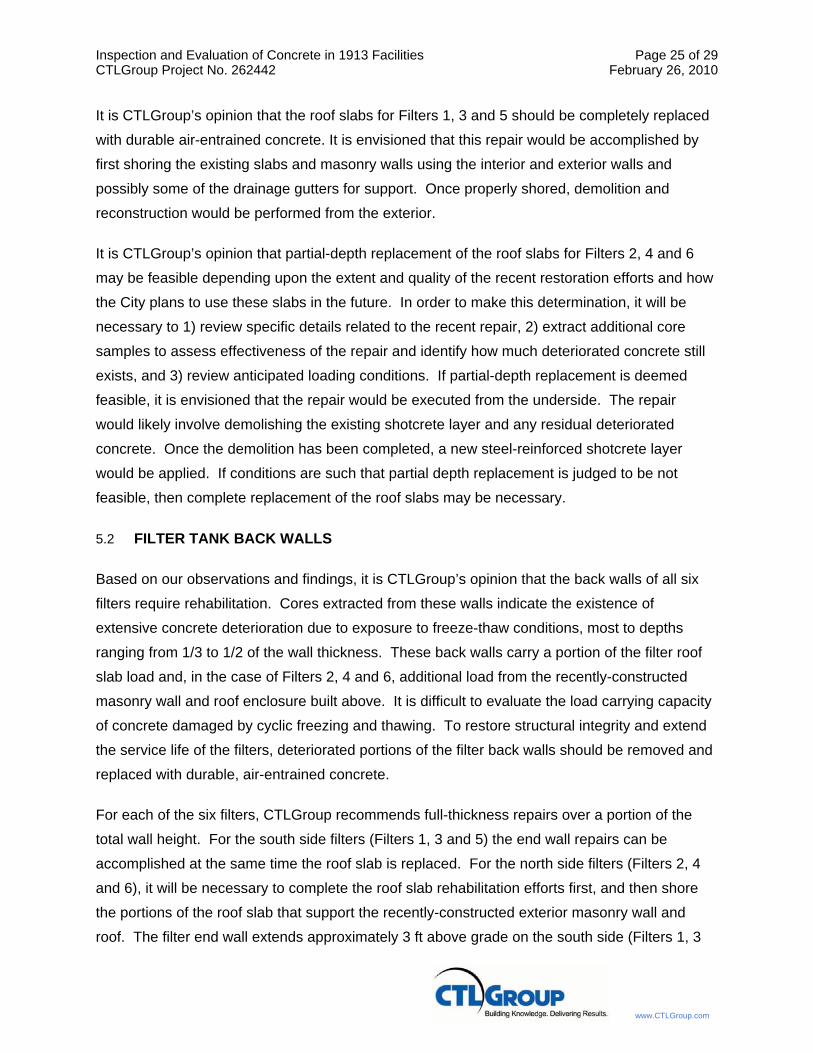
Concrete Core Sample: F-10 EVALUATION SUMMARY
LOCATION: Filter 3, Roof Slab, Exterior Date: January 14, 2009
DIMENSIONS: L = 8 in. D = 2-3/4 in.
REINFORCEMENT: Wire reinforcement observed at interface between original slab concrete and initial topping layer.
COMMENTS: Core extracted by CTLGroup for examination and/or testing.
CRACKING: Cracking observed at interface between original roof slab concrete and concrete topping layer.
MACROSCOPICAL OBSERVATIONS: Core extracted in two pieces. Core incorporates three distinct layers; a 5-3/4 in. thick lightweight topping layer; a 2 in. thick mesh-reinforced concrete topping layer; and a 1/4 in. thick concrete layer (believed to be the original roof slab concrete). A thin line can be seen at the interface between the lightweight topping and concrete topping layers, and likely denotes the use of some kind of bonding agent. Fracture observed in the lightweight topping at a depth of approximately 4-1/4 inches from the top (exposed surface). Fracture passes through and around aggregate. Bottom fracture occurred near interface between original roof slab concrete and concrete topping layer. Fracture passesthrough and around aggregate. White secondary deposits observed on bottom fracture surface.
View of Core F-10. (Exposed Surface at Left Side)

Evaluation of Concrete in 1913 Facilities CTL Project No. 262442
Concrete Core Sample: F-11 EVALUATION SUMMARY
LOCATION: Filter 5, Roof Slab, Exterior, Delaminated area Date: January 14, 2009
DIMENSIONS: L = 7 in. D = 2-3/4 in.
REINFORCEMENT: None observed.
COMMENTS: Core extracted by CTLGroup for examination and/or testing.
CRACKING: Several cracks observed parallel to top (exposed) surface. Cracks occur primarily in outer 4 in. of the 5-1/4 in. thick lightweight topping layer.
MACROSCOPICAL OBSERVATIONS: Core extracted in two pieces. Core incorporates two distinct layers; a 5-1/4 in. thick lightweight topping layer; and a 1-3/4 in. thick concrete topping layer. A light-colored line can be seen at the interface between the two layers, and likely denotes the use of some kind of bonding agent. Fracture observed in the lightweight topping at a depth of approximately 1-1/4 inches from the top (exposed surface). Fracture passes around aggregate, and material adjacent to fracture exhibits extensive cracking. Bottom break occurs around coarse aggregate. A brownish-colored residue exists on the bottom fracture surface, and likely denotes use of some kind of bonding agent applied at the interface between the original roof slab concrete and concrete topping layer.
View of Core F-11. (Exposed Surface at Left Side)

Evaluation of Concrete in 1913 Facilities CTL Project No. 262442
Concrete Core Sample: F-12 EVALUATION SUMMARY
LOCATION: Filter 4, North (Back) Wall, Exterior Date: January 14, 2009
DIMENSIONS: L = 6-1/2 in. D = 3-3/4 in.
REINFORCEMENT: None observed.
COMMENTS: Core extracted by CTLGroup for examination and/or testing.
CRACKING: None observed.
MACROSCOPICAL OBSERVATIONS: Core extracted in one piece. Bottom fracture passes through and around coarse aggregate. White secondary deposits observed on bottom fracture surface.
View of Core F-12. (Exposed Surface at Left Side)
Evaluation of Concrete in 1913 Facilities CTL Project No. 262442
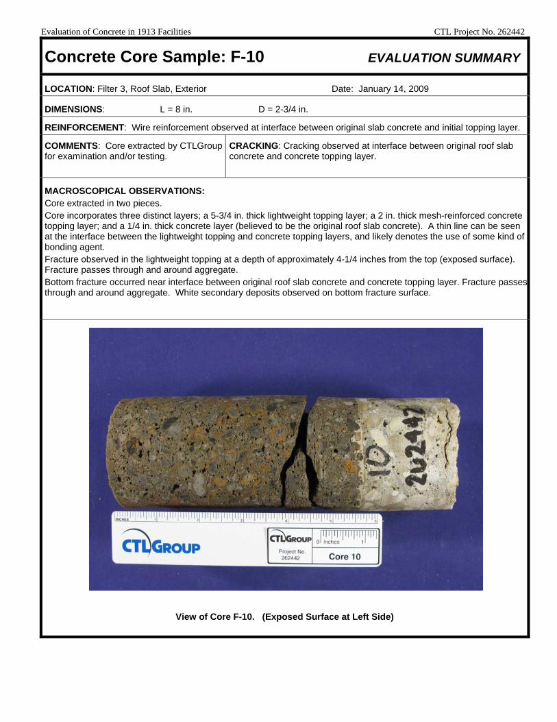
Concrete Core Sample: F-13 EVALUATION SUMMARY
LOCATION: Filter 4, North (Back) Wall, Exterior, Delaminated area Date: January 14, 2009
DIMENSIONS: L = 6-1/2 in. D = 3-3/4 in.
REINFORCEMENT: None observed.
COMMENTS: Core extracted by CTLGroup for examination and/or testing.
CRACKING: Several cracks observed parallel to exposed surface. Cracks located within 4-1/2 in. of exposed surface.
MACROSCOPICAL OBSERVATIONS: Core extracted in two pieces. Fracture between the two segments passes through and around coarse aggregate. Bottom break also passes through and around coarse aggregate. White secondary deposits observed on both intermediate and bottom fracture surfaces.
View of Core F-13. (Exposed Surface at Left Side)

Evaluation of Concrete in 1913 Facilities CTL Project No. 262442
Concrete Core Sample: F-14 EVALUATION SUMMARY
LOCATION: Filter 4, North (Back) Wall, Exterior Date: January 14, 2009
DIMENSIONS: L = 7 in. D = 3-3/4 in.
REINFORCEMENT: None observed.
COMMENTS: Core extracted by CTLGroup for examination and/or testing.
CRACKING: A few coarse aggregate exhibit fine random cracks. A horizontal crack exists across the exterior (exposed) surface of the core. This fine crack can be traced along the sides of the core, and appears to extend to the bottom fracture surface.
MACROSCOPICAL OBSERVATIONS: Core extracted in one piece. Bottom break passes through coarse aggregate. White secondary deposits observed on bottom fracture surface.
View of Core F-14. (Exposed Surface at Left Side)
Evaluation of Concrete in 1913 Facilities CTL Project No. 262442
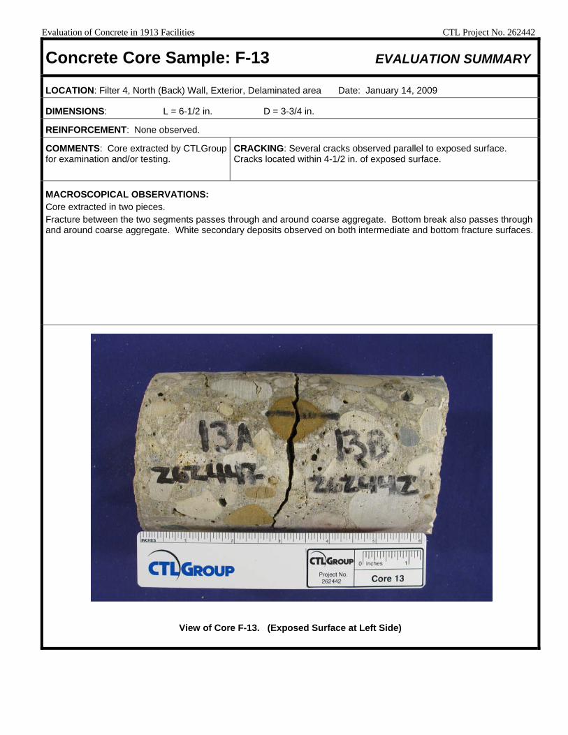
Concrete Core Sample: F-15 EVALUATION SUMMARY
LOCATION: Filter 3, Roof Slab, Exterior, Delaminated area Date: January 14, 2009
DIMENSIONS: L = 11 in. D = 2-3/4 in.
REINFORCEMENT: Wire reinforcement observed at interface between lightweight topping and concrete topping layers.
COMMENTS: Core extracted by CTLGroup for examination and/or testing.
CRACKING: Several cracks observed in innermost concrete layer (believed to be original roof slab concrete). Cracks occur parallel to top (exposed)/bottom break surfaces.
MACROSCOPICAL OBSERVATIONS: Core extracted in four pieces. Core incorporates three distinct layers; a 5-3/4 in. thick lightweight topping layer; a 2 in. thick concrete topping layer; and a 3-1/4 in. thick concrete layer (believed to be the original roof slab concrete). A thin line can be seen at the interface between the three distinct material layers, and likely denotes the use of some kind of bonding agent. Fracture observed in the lightweight topping at a depth of approximately 2-3/4 inches from the top (exposed) surface. Fracture passes through and around aggregate. Fractures observed in innermost concrete layer at depths of approximately 8-1/2 and 9-1/2 inches from the top (exposed) surface. Both fractures pass through and around coarse aggregate. Bottom break passes through and around coarse aggregate. White secondary deposits observed on intermediate and bottom fracture surfaces of the innermost concrete layer.
View of Core F-15. (Exposed Surface at Left Side)

Evaluation of Concrete in 1913 Facilities CTL Project No. 262442
Concrete Core Sample: C-1 EVALUATION SUMMARY
LOCATION: North wall of Clearwell 1, 53-1/2 in. up from floor slab Date: January 22, 2009
DIMENSIONS: L = 9-1/2 in. D = 3-3/4 in.
REINFORCEMENT: None observed.
COMMENTS: Core extracted by CTLGroup for examination and/or testing.
CRACKING: None observed.
MACROSCOPICAL OBSERVATIONS: Core extracted in one piece. Bottom break occurs around coarse aggregate.
View of Core C-1. (Exposed Surface at Left Side)
Evaluation of Concrete in 1913 Facilities CTL Project No. 262442
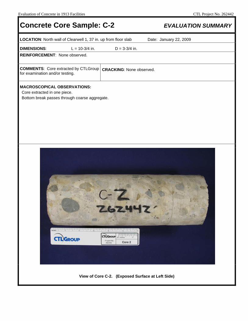
Concrete Core Sample: C-2 EVALUATION SUMMARY
LOCATION: North wall of Clearwell 1, 37 in. up from floor slab Date: January 22, 2009
DIMENSIONS: L = 10-3/4 in. D = 3-3/4 in. REINFORCEMENT: None observed.
COMMENTS: Core extracted by CTLGroup for examination and/or testing.
CRACKING: None observed.
MACROSCOPICAL OBSERVATIONS: Core extracted in one piece. Bottom break passes through coarse aggregate.
View of Core C-2. (Exposed Surface at Left Side)

Evaluation of Concrete in 1913 Facilities CTL Project No. 262442
Concrete Core Sample: C-3 EVALUATION SUMMARY
LOCATION: North wall of Clearwell 1, 37 in. up from floor slab Date: January 22, 2009
DIMENSIONS: L = 10-3/4 in. D = 3-3/4 in. REINFORCEMENT: None observed.
COMMENTS: Core extracted by CTLGroup for examination and/or testing.
CRACKING: None observed.
MACROSCOPICAL OBSERVATIONS: Core extracted in one piece. Bottom break passes through coarse aggregate.
View of Core C-3. (Exposed Surface at Left Side)

Evaluation of Concrete in 1913 Facilities CTL Project No. 262442
Concrete Core Sample: C-4 EVALUATION SUMMARY
LOCATION: West wall of Clearwell 1, 41 in. up from floor slab Date: January 22, 2009
DIMENSIONS: L = 10-1/2 in. D = 3-3/4 in. REINFORCEMENT: None observed.
COMMENTS: Core extracted by CTLGroup for examination and/or testing.
CRACKING: None observed.
MACROSCOPICAL OBSERVATIONS: Core extracted in one piece. Bottom break passes through and around coarse aggregate.
View of Core C-4. (Exposed Surface at Left Side)

Evaluation of Concrete in 1913 Facilities CTL Project No. 262442
Concrete Core Sample: C-5 EVALUATION SUMMARY
LOCATION: South wall of Clearwell 1, 55-1/2 in. up from floor slab Date: January 22, 2009
DIMENSIONS: L = 10-3/4 in. D = 3-3/4 in. REINFORCEMENT: None observed.
COMMENTS: Core extracted by CTLGroup for examination and/or testing.
CRACKING: None observed.
MACROSCOPICAL OBSERVATIONS: Core extracted in one piece. Bottom break passes through and around coarse aggregate.
View of Core C-5. (Exposed Surface at Left Side)

Evaluation of Concrete in 1913 Facilities CTL Project No. 262442
Concrete Core Sample: C-6 EVALUATION SUMMARY
LOCATION: East wall of Clearwell 1, 56 in. up from floor slab Date: January 22, 2009
DIMENSIONS: L = 11 in. D = 3-3/4 in. REINFORCEMENT: None observed.
COMMENTS: Core extracted by CTLGroup for examination and/or testing.
CRACKING: None observed.
MACROSCOPICAL OBSERVATIONS: Core extracted in one piece. Break at bottom of core occurs mostly around coarse aggregate.
View of Core C-6. (Exposed Surface at Left Side)

Evaluation of Concrete in 1913 Facilities CTL Project No. 262442
Concrete Core Sample: C-7 EVALUATION SUMMARY
LOCATION: North wall of Clearwell 1, 60-1/2 in. up from floor slab Date: January 22, 2009
DIMENSIONS: L = 10-1/2 in. D = 3-3/4 in. REINFORCEMENT: None observed.
COMMENTS: Core extracted by CTLGroup for examination and/or testing.
CRACKING: Crack observed that passes through coarse aggregate;
approximately 2 inches in length; crack is roughly parallel to top surface
and is located at a depth of approximately 2 inches from exposed surface.
MACROSCOPICAL OBSERVATIONS: Core extracted in one piece. Bottom break occurs mostly around coarse aggregate.
View of Core C-7. (Exposed Surface at Left Side)

Inspection and Evaluation of Concrete in 1913 Facilities Page B1 of B1 CTLGroup Project No. 262442 February 26, 2010
www.CTLGroup.com
APPENDIX B
Microscopic (Petrograpic) Examination Data
Report for City of Evanston, Water and Sewer Division Project Number 262442 Petrographic Examination of Concrete Cores – Evaluation of Concrete in 1913 Facilities, Evanston, Illinois February 24, 2010 Submitted by: Sang Y. Lee COA # 184-001246 5400 Old Orchard Road Skokie, Illinois 60077-1030 (847) 965-7500 9030 Red Branch Road, Suite 110 Columbia, Maryland 21045 www.CTLGroup.com
Copy No. 1

www.CTLGroup.com
Corporate Office: 5400 Old Orchard Road Skokie, Illinois 60077-1030 Phone: 847-965-7500 Fax: 847-965-6541 Washington D.C. Office: 9030 Red Branch Road, Suite 110 Columbia, Maryland 21045-2003 Phone: 410-997-0400 Fax: 410-997-8480
CTLGroup is a registered d/b/a of Construction Technology Laboratories, Inc.
REPORT OF PETROGRAPHIC EXAMINATION
Date: February 17, 2010
CTLGroup Project No.: 262442
Petrographic Examination of Concrete Cores – Evaluation of Concrete in 1913 Facilities, Evanston, Illinois
Two concrete cores (Figs. 1 and 2) were received on January 29, 2009 from Mr. John Roller,
Principal Structural Engineer of CTLGroup. The cores were extracted by CTLGroup for
examination. Core identification and locations are summarized in Table 1.
TABLE 1 CORE IDENTIFICATION AND LOCATIONS
Core ID Location Comments
C-7 North wall of Clearwell 1, 60.6 in. up from floor slab Core extracted in one piece.
F-15 Filter 3, Roof slab, exterior, delaminated area
Core extracted in four pieces. Core incorporates three distinct layers; a 5.7 in. thick lightweight topping layer, a 2 in. thick concrete topping layer, and a 3.3 in. thick concrete layer (believed to the base roof slab concrete). A fracture was observed in the lightweight topping at a depth of approximately 2.8 in. from the top surface. Fractures were observed in the base concrete at depths of approximately 8.5 and 9.5 in. from the top surface.
Petrographic Examination (ASTM C 856) was requested to evaluate general quality and
condition, and to describe general characteristics of the concrete represented by the cores.
FINDINGS
Main findings of petrographic examination are described below. Additional information is
provided in the attached figure pages and data sheets.
Core C-7 (Core from North Wall of Clearwell 1)
The outer approximately 0.2 to 0.3 in. of the concrete is soft and crumbly (Figs. 1a and 3).
Microscopical examination reveals that the soft, carbonated surface paste (Fig. 4) and some of

City of Evanston Purchasing Division Page 3 of 18 Evaluation of Concrete in 1913 Facilities February 17, 2010 CTLGroup Project No. 262442
www.CTLGroup.com
the underlying harder non-carbonated paste has been partially leached of soluble constituents,
such as calcium hydroxide. Additionally, the outer approximately 0.1 to 0.2 in. of the carbonated
surface paste zone is partially leached of calcium carbonate (Fig. 5). The softening and
apparent leaching of the surface concrete, particularly carbonate compounds from the
carbonated paste, suggests that the concrete may have been exposed to an aggressive
solution. This chemical attack was probably mild, but slowly progressive. Such mild attack of
carbonate compounds has been known to occur in concrete exposed to slightly acidic water
(i.e., carbonic acid attack), soft water, and in some cases, certain organic or vegetative growth
(certain bacteria, algae, etc.).
Apart from the deteriorated outer surface region, the concrete is in generally good condition. No
visible cracks or excessive microcracks are observed in the body of the concrete. Relatively
small amounts of clear to milky alkali-silica reaction (ASR) gel deposits line a few voids, which is
not considered deleterious (no distress is associated with the occurrence of the gel deposits).
The concrete contains siliceous and calcareous aggregates in a hardened portland cement
paste. The hardened paste in the core body is moderately soft and somewhat absorptive.
Paste-aggregate bond is moderately weak. These observed physical paste properties are
generally consistent with concrete made and placed with moderately high water-cement ratio.
The concrete is not air entrained, and the estimated total air content is 1 to 2%. Depth of
carbonation is approximately 0.3 to 0.4 in. from the outer surface based on pH indicator
(phenolphthalein) test (Fig. 4).
Core F-15 (Core from Roof Slab)
The core consists of lightweight topping (5.6 to 5.7 in. thick), concrete topping (1.9 to 2.1 in.
thick), and base concrete (3 to 3.6 in., partial thickness, Figs. 6 and 7). A gray and a yellowish
gray resinous material (likely bonding agents) are observed at the interface between the two
topping layers, and the interface between the concrete topping and the base concrete,
respectively.
Lightweight Topping: The lightweight topping exhibits a sub-horizontal crack at a depth of 2.3
to 2.8 in. from the top surface. A few sub-horizontal to oblique microcracks are also observed
near the crack (Fig. 8). These observed cracks and microcracks pass through aggregate
particles. The topping was split during sample preparation (cutting) along one of the microcracks
located at a depth of approximately 3 to 3.5 in. from the top surface. Apart from these localized

City of Evanston Purchasing Division Page 4 of 18 Evaluation of Concrete in 1913 Facilities February 17, 2010 CTLGroup Project No. 262442
www.CTLGroup.com
crack and microcracks, the lightweight topping is generally sound and in good condition with no
visible cracks and excessive microcracks. Based on petrographic examination, these localized
crack and microcracks are not related to any deleterious chemical reactions within the concrete.
The paste along the crack walls exhibits no carbonation. Small amounts of white deposits
(mostly calcium carbonate) are locally observed in the crack.
The topping contains crushed lightweight aggregates (expanded shale) in a hardened
cementitious paste consisting of portland cement and fly ash. Aggregate particles visually
appear evenly graded to an observed top size of 0.35 in. (9 mm), and uniformly distributed
throughout the body. The topping exhibits relatively good physical paste properties. The
hardened paste is relatively hard and dense (water droplets applied to fresh fractures are slowly
absorbed by the paste). Paste-aggregate bond is tight.
The topping appears to be air-entrained, and the estimated total air content is 10 to 13%. The
overall air-void system is relatively coarse (air voids coarser than 0.04 in. are abundant). Many
voids are lined with secondary ettringite and lesser calcium carbonate deposits. Presence of
these deposits in voids is not considered deleterious, and typically indicates abundance of
moisture within the topping. Depth of carbonation is approximately 0.5 to 0.6 in. from the top
surface based on pH indicator (phenolphthalein) test (Fig. 7). The bonding between the
lightweight topping and the underlying concrete topping is tight (the topping layers do not split
along the interface when hit with a hammer).
Concrete Topping: The topping concrete is in good condition. No significant distress (cracks or
excessive microcracks) or deleterious chemical reactions are observed. Trace amounts of clear
to milky white ASR gel deposits line a few voids, which is not considered deleterious (no
distress is associated with the observed gel deposits).
The topping contains calcareous and siliceous gravel coarse aggregate and sand fine
aggregate in a hardened portland cement paste. The aggregate particles visually appear evenly
graded to an observed top size of 0.4 in., and uniformly distributed throughout the body of the
concrete. The concrete exhibits good physical paste properties. The hardened paste is relatively
hard and very dense. Water droplets applied to freshly fractured surfaces are very slowly
absorbed or slightly bead instead of being spread and absorbed by the paste. The concrete is
air entrained, and estimated total air content is 3 to 4%.

City of Evanston Purchasing Division Page 5 of 18 Evaluation of Concrete in 1913 Facilities February 17, 2010 CTLGroup Project No. 262442
www.CTLGroup.com
Bonding between the concrete topping and the underlying base concrete is relatively weak. The
resinous bonding agent is locally separated from the underlying base concrete. The bonding
agent is stained yellowish brown, and locally somewhat soft (likely indication of deterioration).
Base Concrete: The concrete is in poor condition. Narrowly-spaced, sub-horizontal cracks and
microcracks are observed through the depth (partial depth), passing through and around
aggregate particles (Fig. 9). Based on petrographic examination, these observed cracks and
microcracks are mainly attributed to damage caused by cyclic freezing and thawing of non-air-
entrained concrete while critically saturated with water. The concrete is not air entrained with the
estimated total air content less than 1% (Fig. 10).
Relatively small amounts of ASR gel deposits are locally observed in a few cracks and voids.
These gel deposits are judged to be secondary deposits filled into the pre-existing freeze-thaw
cracks and voids rather than contributing to the occurrence of the cracking based on lack of
randomly-oriented cracks and microcracks extending out of any reacting aggregate particles.
The base concrete contains siliceous and calcareous coarse and fine aggregates in a hardened
portland cement paste. The aggregate particles visually appear evenly graded to an observed
top size of 0.8 in., and uniformly distributed throughout the body of the concrete. The hardened
concrete paste in the intact areas away from the cracks is moderately hard and fairly dense.
The paste along the cracks is locally softer and more absorptive. Secondary ettringite and
calcium carbonate deposits are abundant in the cracks, indicating abundance of moisture within
the concrete, and possible infiltration and migration of moisture along the cracks.
METHODS OF TEST
Petrographic examination of the provided cores was performed in accordance with ASTM
C 856-04, "Standard Practice for Petrographic Examination of Hardened Concrete." The cores
were visually inspected and photographed as received. The distressed (cracked) portion of Core
F-15 was applied with epoxy to preserve as-received condition and to prevent damage during
sample preparation. After the epoxy hardened, each core was cut half longitudinally and one of
the resulting sides of the slice was ground (lapped) to produce a smooth, flat, semi-polished
surface. Lapped and freshly broken surfaces of the cores were examined using a
stereomicroscope at magnifications up to 45X. For thin-section study, small rectangular blocks
were cut from the top surface portion of Core C-7, and in the body of lightweight topping and

City of Evanston Purchasing Division Page 6 of 18 Evaluation of Concrete in 1913 Facilities February 17, 2010 CTLGroup Project No. 262442
www.CTLGroup.com
from near the boundary between the concrete topping and the base concrete in Core F-15. One
side of each block was lapped to produce a smooth, flat surface. The blocks were cleaned and
dried, and the prepared surfaces were mounted on separate ground glass microscope slides
with epoxy resin. After the epoxy hardened, the thickness of the mounted blocks was reduced to
approximately 20 μm (0.0008 in.). The resulting thin sections were examined using a polarized-
light (petrographic) microscope at magnifications up to 400X to study aggregate and paste
mineralogy and microstructure.
Estimated water-cement (w/c), when reported, is based on observed concrete and paste
properties including, but not limited to: 1) relative amounts of residual (unhydrated and partially
hydrated) portland cement clinker particles, 2) amount and size of calcium hydroxide crystals, 3)
paste hardness, color, and luster, 4) paste-aggregate bond, and 5) relative absorbency of paste
as indicated by the readiness of a freshly fractured surface to absorb applied water droplets.
These techniques have been widely used by industry professionals to estimate w/c.
Depth and pattern of paste carbonation was determined by application of a pH indicator solution
(phenolphthalein) to freshly cut and fractured concrete surfaces. The solution imparts a deep
magenta stain to high pH, non-carbonated paste.
Sang Y. Lee, Ph.D. Senior Microscopist Microscopy Group SYL/lsy Notes: 1. Results refer specifically to the samples submitted. 2. This report may not be reproduced except in its entirety. 3. The samples will be retained for 30 days, after which they will be discarded unless we hear
otherwise from you.

City of Evanston Purchasing Division Page 7 of 18 Evaluation of Concrete in 1913 Facilities February 17, 2010 CTLGroup Project No. 262442
www.CTLGroup.com
1a. Outer surface.
1b. Side view. Outer surface is to the left.
Fig. 1 Core C-7 as received for examination. Scale is marked in inches.

City of Evanston Purchasing Division Page 8 of 18 Evaluation of Concrete in 1913 Facilities February 17, 2010 CTLGroup Project No. 262442
www.CTLGroup.com
2a. Top surface.
2b. Side view. Top surface is to the left. Arrows designate fractures occurred during coring.
Fig. 2 Core F-15 as received for examination. Scale is marked in inches.
Top surface
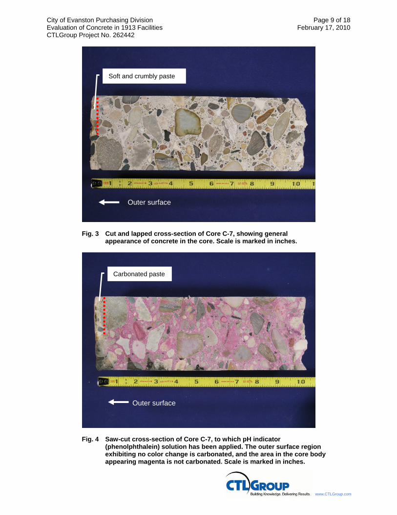
City of Evanston Purchasing Division Page 9 of 18 Evaluation of Concrete in 1913 Facilities February 17, 2010 CTLGroup Project No. 262442
www.CTLGroup.com
Fig. 3 Cut and lapped cross-section of Core C-7, showing general appearance of concrete in the core. Scale is marked in inches.
Fig. 4 Saw-cut cross-section of Core C-7, to which pH indicator (phenolphthalein) solution has been applied. The outer surface region exhibiting no color change is carbonated, and the area in the core body appearing magenta is not carbonated. Scale is marked in inches.
Carbonated paste
Outer surface
Soft and crumbly paste
Outer surface

City of Evanston Purchasing Division Page 10 of 18 Evaluation of Concrete in 1913 Facilities February 17, 2010 CTLGroup Project No. 262442
www.CTLGroup.com
5a. Plane polarized light.
5b. Same field of view, but in cross-polarized light.
Fig. 5 Thin-section photomicrographs showing deteriorated outer surface region of Core C-7. Calcium carbonate is locally leached from the deteriorated and carbonated surface paste zone.
Out
er S
urfa
ce
Deteriorated paste
Out
er S
urfa
ce
Leaching of calcium carbonate from carbonated paste
Outer surface

City of Evanston Purchasing Division Page 11 of 18 Evaluation of Concrete in 1913 Facilities February 17, 2010 CTLGroup Project No. 262442
www.CTLGroup.com
Fig. 6 Cut and lapped cross-section of Core F-15 showing topping layers and base concrete. Top surface is up. Scale is marked in inches.
Fig. 7 Saw-cut cross-section of Core F-15, to which pH indicator (phenolphthalein) solution has been applied. The top surface region exhibiting no color change is carbonated, and the area in the core body appearing magenta is not carbonated. Top surface is up. Scale is marked in inches.
Lightweight topping
Concrete topping
Base concrete
Lightweight topping
Concrete topping
Base concrete
Carbonated paste

City of Evanston Purchasing Division Page 12 of 18 Evaluation of Concrete in 1913 Facilities February 17, 2010 CTLGroup Project No. 262442
www.CTLGroup.com
Fig. 8 Image showing lightweight topping in Core F-15. The red arrow designates a crack observed in the core as received. The yellow arrows designate a crack that occurred during sample preparation in laboratory. Scale is marked in inches.
Fig. 9 Image showing the concrete topping and the base concrete in Core F-15. The concrete topping exhibits no visible cracks. The base concrete exhibits closely-spaced sub-horizontal cracks (the cracks are traced with a black pen to highlight).
Concrete topping
Base concrete
Fig. 10

City of Evanston Purchasing Division Page 13 of 18 Evaluation of Concrete in 1913 Facilities February 17, 2010 CTLGroup Project No. 262442
www.CTLGroup.com
Fig. 10 Stereomicroscope image showing the area designated by the red box in Fig. 9. Lack of small, spherical voids at the lapped surface indicate that the base concrete in Core F-15 was not air entrained. Scale increments are 0.04 in.

City of Evanston Purchasing Division Page 14 of 18 Evaluation of Concrete in 1913 Facilities February 17, 2010 CTLGroup Project No. 262442
www.CTLGroup.com
PETROGRAPHIC EXAMINATION OF HARDENED CONCRETE, ASTM C 856
STRUCTURE: Concrete wall DATE RECEIVED: January 29, 2009
LOCATION: Evanston, Illinois EXAMINED BY: Sang Lee
SAMPLE
Client Identification: C-7.
CTLGroup Identification: 2508001.
Dimensions: Core diameter = 3.7 in. (94 mm), core length = approximately 10.5 to 10.7 in. (267 to 272 mm); partial wall thickness.
Outer Surface: The intact portion of the surface is even and paste-rich. The surface is locally irregular and deteriorated with exposed aggregate particles to a depth of approximately 0.2 in. (5 mm). The concrete at the surface is soft and locally crumbly.
Bottom Surface: Irregular, rough fractured surface.
Cracks, Joints, Large Voids: No visible cracks, joints, or large voids are observed.
Reinforcement: No reinforcement is observed in the core submitted.
AGGREGATES
Coarse: Siliceous and calcareous rocks consisting mainly of limestone, dolomitic limestone, coarse to medium-grained granitic and metamorphic rocks, sandstone, fine-grained sedimentary rocks, and chert.
Fine: Siliceous and calcareous sand consisting of quartz, feldspar, limestone, various igneous rocks, quartzite, fine-grained sedimentary rocks, and chert with small amounts of other rocks and minerals.
Gradation & Top Size: Visually appears evenly graded to an observed top size of 1.3 in. (33 mm).
Shape, Texture, Distribution: Both coarse and fine aggregate particles are mostly rounded to subangular and equant to oblong with smooth to slightly rough surface texture; uniformly distributed.
PASTE
Color: Light buff gray in the top approximately 0.2 to 0.3 in. (5 to 8 mm), and light gray in the remaining portion of the core body.
Hardness: Soft and crumbly in the top approximately 0.2 to 0.3 in. (5 to 8 mm); moderately soft in the remaining body portion of the core.
Luster: Dull.
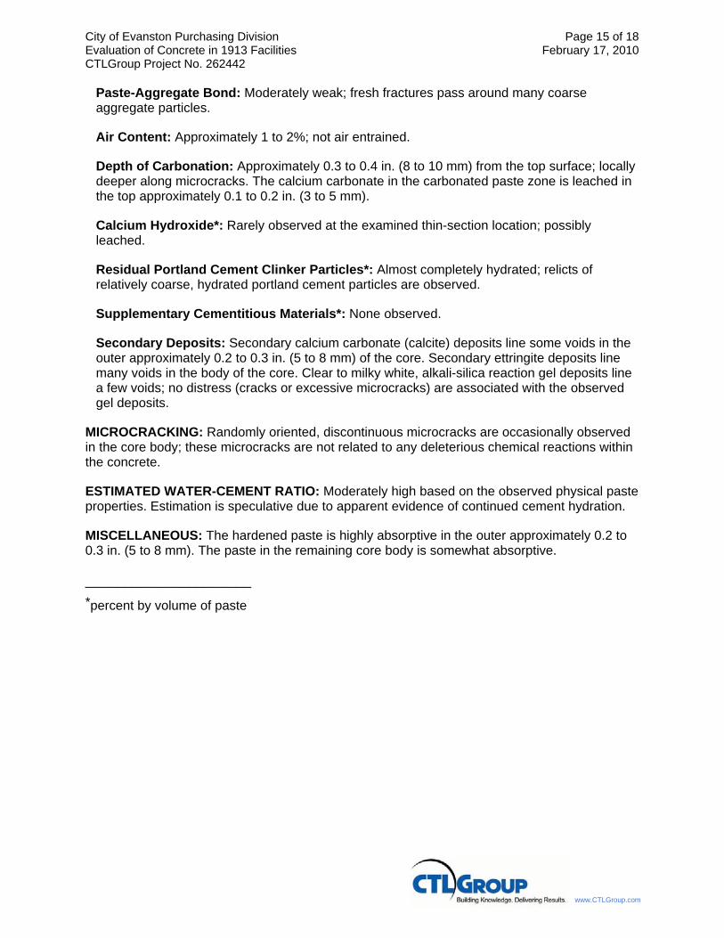
City of Evanston Purchasing Division Page 15 of 18 Evaluation of Concrete in 1913 Facilities February 17, 2010 CTLGroup Project No. 262442
www.CTLGroup.com
Paste-Aggregate Bond: Moderately weak; fresh fractures pass around many coarse aggregate particles.
Air Content: Approximately 1 to 2%; not air entrained.
Depth of Carbonation: Approximately 0.3 to 0.4 in. (8 to 10 mm) from the top surface; locally deeper along microcracks. The calcium carbonate in the carbonated paste zone is leached in the top approximately 0.1 to 0.2 in. (3 to 5 mm).
Calcium Hydroxide*: Rarely observed at the examined thin-section location; possibly leached.
Residual Portland Cement Clinker Particles*: Almost completely hydrated; relicts of relatively coarse, hydrated portland cement particles are observed.
Supplementary Cementitious Materials*: None observed.
Secondary Deposits: Secondary calcium carbonate (calcite) deposits line some voids in the outer approximately 0.2 to 0.3 in. (5 to 8 mm) of the core. Secondary ettringite deposits line many voids in the body of the core. Clear to milky white, alkali-silica reaction gel deposits line a few voids; no distress (cracks or excessive microcracks) are associated with the observed gel deposits.
MICROCRACKING: Randomly oriented, discontinuous microcracks are occasionally observed in the core body; these microcracks are not related to any deleterious chemical reactions within the concrete.
ESTIMATED WATER-CEMENT RATIO: Moderately high based on the observed physical paste properties. Estimation is speculative due to apparent evidence of continued cement hydration.
MISCELLANEOUS: The hardened paste is highly absorptive in the outer approximately 0.2 to 0.3 in. (5 to 8 mm). The paste in the remaining core body is somewhat absorptive.
_____________________ *percent by volume of paste

City of Evanston Purchasing Division Page 16 of 18 Evaluation of Concrete in 1913 Facilities February 17, 2010 CTLGroup Project No. 262442
www.CTLGroup.com
PETROGRAPHIC EXAMINATION OF HARDENED CONCRETE, ASTM C 856
STRUCTURE: Concrete roof slab DATE RECEIVED: January 29, 2009
LOCATION: Evanston, Illinois EXAMINED BY: Sang Lee
SAMPLE
Client Identification: F-15
CTLGroup Identification: 2508002.
Dimensions: Core diameter = 4.2 in. (107 mm), core length = approximately 10.6 to 11 in. (269 to 279 mm); partial roof slab thickness. The core consists of three layers; (1) 5.6 to 5.7-in. (142 to 145-mm) thick lightweight topping, (2) 1.9 to 2.1-in. (48 to 53- mm) thick concrete topping, and (3) 3 to 3.6-in. (76 to 91-mm) thick base concrete. A gray resinous material (likely bonding agent) is observed at the interface between two topping layers. A yellowish gray resinous material (likely bonding agent) is observed at the interface between the concrete topping and the base concrete.
Top Surface: Even, somewhat rough surface with partially exposed sand particles.
Bottom Surface: Irregular, rough fractured surface.
Joints, Large Voids: No joints or large voids are observed.
Reinforcement: Steel wires (0.23 in. or 6 mm diameter) or a wire mesh are embedded in the lightweight topping at a depth of 5.1 to 5.3 in. (130 to 135 mm) below the top surface. No steel reinforcement is observed either in the concrete topping or the base concrete in the submitted core.
LIGHTWEIGHT TOPPING
The topping contains crushed lightweight aggregates (expanded shale) in a hardened cementitious paste consisting of portland cement and fly ash. Aggregate particles visually appear evenly graded to an observed top size of 0.35 in. (9 mm), and uniformly distributed throughout the body. The hardened paste is relatively hard and dense (water droplets applied to fresh fractures are slowly absorbed by the paste). Paste-aggregate bond is tight.
The concrete appears to be air entrained, and the estimated total air content is 10 to 13%. Overall air-void system is relatively coarse (air voids coarser than 0.04 in. or 1 mm are abundant). Many voids are lined with secondary ettringite and calcium carbonate deposits. Similar calcium carbonate deposits are locally observed in the observed crack. Depth of carbonation is approximately 0.5 to 0.6 in. (13 to 15 mm) from the top surface based on pH indicator (phenolphthalein) test.
A sub-horizontal crack is observed at a depth of 2.3 to 2.8 in. (58 to 71 mm) from the top surface. A few sub-horizontal microcracks are observed near the crack. These observed cracks and microcracks pass through aggregate particles. The topping was split during sample preparation (cutting) along a microcrack located at a depth of approximately 3 to 3.5 in. (76 to 89 mm) from the top surface. Apart from these localized crack and microcracks, the

City of Evanston Purchasing Division Page 17 of 18 Evaluation of Concrete in 1913 Facilities February 17, 2010 CTLGroup Project No. 262442
www.CTLGroup.com
lightweight topping is generally sound with no visible cracks and excessive microcracks. The lightweight topping is tightly bonded to the underlying concrete topping.
CONCRETE TOPPING
The concrete topping contains calcareous and siliceous gravel coarse aggregate and sand fine aggregate in a hardened portland cement paste. The aggregate particles visually appear evenly graded to an observed top size of 0.4 in. (10 mm), and uniformly distributed throughout the body of the concrete. The hardened paste is relatively hard and very dense. Water droplets applied to fresh fracture are very slowly absorbed by the paste or locally slightly bead instead of being spread and absorbed by the paste. The concrete is air entrained, and estimated total air content is 3 to 4%; the entrained air voids are locally somewhat widely-spaced.
No visible cracks are observed. A few, discontinuous, randomly-oriented microcracks are observed in the body of the topping; these microcracks are not related to any deleterious reactions within the concrete. Secondary ettringite deposits line some voids. Trace amount of clear to milky white alkali-silica reaction (ASR) gel deposits is observed in a void; no distress (cracks or microcracks) is associated with the gel deposits.
Bonding between the concrete topping and the base concrete is weak. The yellowish resinous bonding agent is locally separated from the underlying base concrete. The bonding agent is locally somewhat soft (likely indication of deterioration).
BASE CONCRETE
Aggregate
Coarse: Gravel consisting mainly of limestone and dolomitic limestone with lesser chert and other siliceous rocks.
Fine: Siliceous and calcareous sand consisting of quartz, feldspar, limestone, quartzite, igneous rocks, sandstone, chert, and relatively small amounts of other rocks/minerals.
Gradation & Top Size: Visually appears evenly graded to an observed top size of 0.8 in. (18 mm).
Shape, Texture, Distribution: Coarse – mostly rounded to subangular and equant to oblong with generally smooth surface texture; uniformly distributed. Fine – mostly sub-angular to rounded and equant to oblong; uniformly distributed.
Paste
Color: Light to light medium gray.
Hardness: Moderately hard; locally moderately soft along cracks.
Luster: Dull to subvitreous; dull along cracks.
Paste-Aggregate Bond: Paste-aggregate bond is not evaluated due to abundance of cracks.

City of Evanston Purchasing Division Page 18 of 18 Evaluation of Concrete in 1913 Facilities February 17, 2010 CTLGroup Project No. 262442
www.CTLGroup.com
Air Content: Less than 1%; the concrete is not air entrained.
Depth of Carbonation: Localized paste carbonation is observed along the top surface of the base concrete, and along some cracks.
Calcium Hydroxide*: Calcium hydroxide is not observed; possible leached.
Residual Portland Cement Clinker Particles*: Relics and small amounts of partially hydrated, coarse (up to 0.008 in. or 200 μm) portland cement particles are randomly distributed in the paste.
Supplementary Cementitious Materials*: None observed.
Secondary Deposits: Many cracks and microcracks are lined with ettringite, calcium carbonate, and small amount of wedge-shaped crystals (likely gypsum). Small amounts of clear to milky white, alkali-silica reaction (ASR) gel deposits locally line a few cracks and voids.
Cracking: Closely-spaced, sub-horizontal cracks are observed throughout the depth, passing through and around aggregate particles.
Microcracking: Sub-horizontal microcracks are abundant through the depth of the concrete, passing through and around aggregate particles.
Estimated Water-Cement Ratio: Not estimated due severity of distress (cracks and microcracks).
Miscellaneous: The hardened paste is fairly dense in the intact areas away from the cracks. The paste is locally absorptive along the cracks.
_____________________ *percent by volume of paste