inspection and a trial fit in our core grid plate,
TRANSCRIPT

.
. .
$( lh ol, 01
ENGINEERING [2'
& APPLIED SCIENCEFebruary 12, 1991
lbif|RT%ll N1 Of AM I L4R I ADI\lI RIADd i NDI\/ l RI\D I'll)3f( A
Mr. Marvin M. Mendonca, Senior Project Managerlion-Power Reactor, Decommissioning and g g. ,4 g y ;,
Environmental Project Directorate # " * " # 'I ,Division of Reactor Projects - III, IV, V and ,
*
Special Projects ~
Office of 11uclear Reactor Regulationliuclear Regulatory CommissionWashington, D.C. 20555
Subject U.Va. 's Reply to liRC's Request for Additional Information,with respect to the UVAR LEU Fuel Conversion Application: DocketNo. 50-62.
Dear Mr. Mendonoa
Please find enclosed the additional information recentlyrequested. We appreciate tne time extension which was provided tothe University of Virginia (U.Va. ) to respond to the questionnaire.We hope that this information will be useful in bringing to aspeedy conclusion the evaluation of U.Va. 's application to convertto LEU fuel.
As regards the schedule for conversion, we look forward toreceiving from B&W the " dummy" LEU fuel elements, for dimensionaltolerance inspection and a trial fit in our core grid plate,sometime this spring. In addition, we have been informed verballyby EG&G, Idaho, that the first UVAR LEU core manuf acture will beconcluded by B&W 1 ate this fall. Therefore, the conversion couldtake place at the end of this year, or early next year.
Please note our great concern, briefly stated in the first LEUcore test plan included in our response, regarding the futureavailability to us of a suitable spent-fuel shipping cask at a timeto coincide with the URC's order to convert. We are keepingabreast of developments with the cask owned by Centichem. Itappears that it will be held, and not rented, until Contichem isable to decommission its reactor and finish shipping its fuel. Weare not auare of any provisions being taken in regards to futuretransfer of ownership of the cask. Therefore, the informationpresently available strongly suggests that a snag in the conversionschedule is likely.
09102260181 910212 k j\IPDR ADOCK 05000062 jP PDR

. .
(page 2, continued)
The NRC should be made aware that U.Va. does not wish tomaintain sizeable amounts of HEU fuel onsite and out-of-core for anindeterminate period of time, as a result of a prematureconversion, because this would necessitate taking enhanced securitymeasures that U.Va. can ill afford. At this time, we respectfullyrequest the NRC to hold off on issuing its order.to convert untilsuch time that this issue is satisfactorily resolved - for- all-concerned. Please note that there is sufficient HEU fuel availablefor Va. to postpone the conversion of its reactor until the HEUspent fuel is shipped off-site. Coordination between the NRC, DOEand us will be-much appreciated.
i'
.Since e y/ k,
f .) r
tv 'cRobert U. Mulder, DirectorUniversity of Virginia .
'
Reactor Facility* ' County of MenarhI
Lemmormeafth of VitEinia
' I hereby certify that the attached document is a trulandexact copy of a I+7 Nff
. presented beforesi,n e a m n. v
rne this J@ dayof _ Feb-- , 1,g~
tv -h**n h>rb ([JQ{ p f*a*-n .up,,ni, - _,
} tr l Lt y,g-~
14 commission empires -- % 28 g9ff
,
Enclosuret Replies to NRC Questionnaire-'
(" Request for Additional Information")cet NRC, Washington D.C.
NRC Region II, Atlanta, Georgia. ;- '
DOE, Washington--D.C.EG&G,-Idaho !-
'
;
i
O. .
Question #1:
We understand from discussions with your staff that because of the timingof issuance, your application _did not reference or utilize NUREG 1313 for theacceptability of the Low Enriched Uranium (LEU) silicide. aluminum d!.'persionfuel, provide rationals for the technical acceptability of your-LEU fuel,You may utilize and reference the evaluations in NUREG 1313 provided thatyou assess and show applicability to your reactor and it's operating conditions,
,
_ _. _ _ _ _
J

|.- .
|
-|
Reply to NRC Request for Additional Information, Question 1:j
NUREG-1313 was reviewed to reconsider the acceptability of theproposed Low Enriched Uranium (LEUfuel, in light of "new" information.) silicide-aluminum dispersion'iIt is noted that this report
was not available to this licensee at the time the LEU SafetyAnalysis Report (UVAR LEU SAR)- for the University of VirginiaReactor (UVAR) was in preparation. Previous staff considerationwith regards to fuel acceptability consisted of a critical reviewof UVAR LEU fuel . plate and element design specifications(contracts) which were drafted by EG&G, Idaho for the fuel elementmanufacturer, Babcock and Wilcox, in Lynchburg, Va. , as well as theresults of fuel element design calculations performed by staff andstudents in support of the UVAR LEU SAR.
In response to thn NRC request, the data-presented in NUREG-1313 was analyzed for conformance with the postulations used in theUVAR LEU SAR. The conclusion reached by the reactor staff is that .
the UVAR LEU SAR does not need revision, because the results of _]
considerable in-core testing have shown that the new high-density- -|U3Si2 4fuel does not behave significantly different-from the UAlx
!fuel in present use. The points worthy of note are:4
1) An exothermic reaction between U3Si2 and aluminum-clad occurs atabout 1140 'F, a temperature above the melting point of the Al 6061cladding material. It is noted that the calculated maximum }
temperature reached in any UVAR LEU core accident involving a loss-of coolant is 775 'FTherefore, this reac, tion need not be considerated in the LEU SAR.below the clad softening point-(see LEU SAR).2) Fission product release does not occur until thepoint of the U3Si2 fuel is reached, which is about 950 blistering'F (lowerend of range). As already stated above in point #1, the maximumtemperature for any analyzed transient.is 775 'F,1 significantly
-
i
below the bl stering poin; of the new fuel.|
3,) The thermal property values for the LEU fuel which were used inthe UVAR LEU SAR are in agreement with those listed in Appendix Aof NUREG-1313.
.
1
e

.
. .
.
,
Question #2:
Provide a description of your initial core loadipg plans and testingprogram to assure that core parameters are'consisten,twith yo':r safety-analys*sassumptions and Technical Specification requirements. Include considerations.for reactor coolant flow rate, worth of each control rod. power. distribution,-.shutdown margin, and excess reactivity. Also, include acceptance criteria forparameters and attions to be taken when not met. Compare the planned. initial
.
LEU core with the HEU core it will replace.o
>
'
,,
.,
'.
);i
.1
!
|
|
1
1
1
:
1..

. - _ _ . .. .. ~. . -
, .,
h
LEU First Core Test Pronram i
University of Virginia Research ReactorLicense No. R-66, Docket No. 50-62
| I. IntroductionF
' ;
LEU fuel will only be accepted by U.Va. contingent on a spent fuel caskbeing available to ship HEU fuel off site during the scheduled conversionperiod.
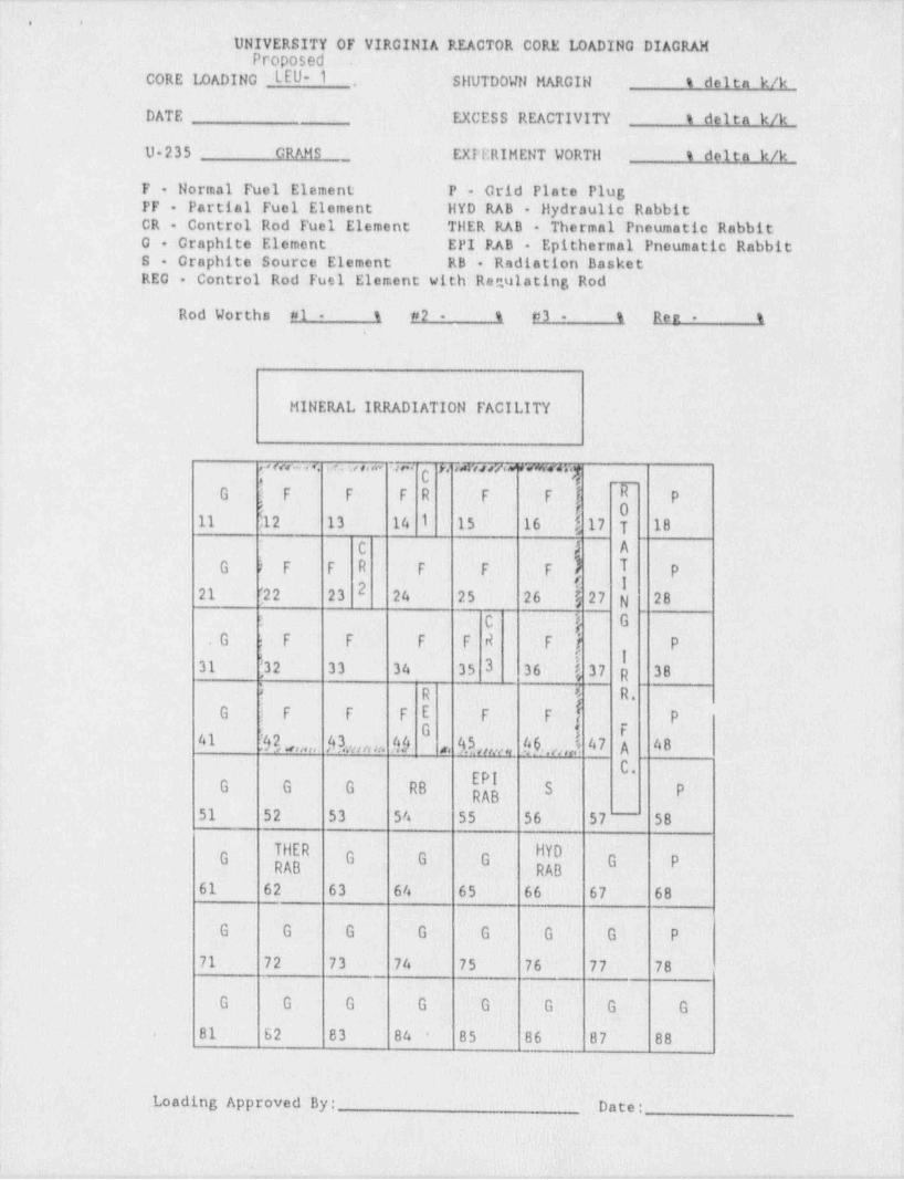
The LEU fuel will-be loaded into the UVAR reactor according to the standardoperating procedures which have applied to HEU cores and which will still beapplicable to LEU cores. Attached is a copy of a crocosed low enriched uraniumcore loading (LEU-1), which is. suitable for experimental-requirements. In theactual LEU-1 core, partial fuel: elements may have to be used in place of full-elements to meet shutdown margin and excess reactivity requirements. Corner .
element in position 42 may be substituted with a graphite element were the-core to go critical ytth fewer than 18 equivalent full elements. When theloading has been'estabilshed certain tests will be performed to assurecompliance with Tech. Spec.(TS) requirements.
A. Core Loadinn:
The LEU fuel will be loaded into the UVAR reactor = grid-plate according-l
to UVAR Ctandard Operating Procedures (UVAR SOP 5.4.A). -First,1 the control-rods and their associated fuel elements will be loaded'into the grid plate and roddrop tests vill be performed to assure they conform to the requirements of theLEU Technical Specifications. Suberitical multiplication measurements will be *
made after the addition of each standard LEU fuel element with the rods at 10-inches and at 26 inches. The LED fuel loading configuration will be adjustedsuch that the critical rod positions are.not less than - 11.00 inches.
,
After criticality has been established and before raising;the power level4
above 1 kW as indicated by the instrumentation, the following tests will beperformed to assure that all LEU Tech.'-Spec. requirements are met:
.
1) All control rods ~will be calibrated to determine the integral worthof each rod. From the initial critical rod positions, the shutdown marginand excess reactivity will be determined.-If the parameters do not ecnformwith the Tech. Specs., the LEU-1 core loading will be modified and the testirepeated until ttn parameters fall within TS limits.
2) The total-coolant flow rate'through the. core will be measured'using an-orifice plate installed in the primary piping. A determination'of flowcoast after a simulated loss of primary pump power will'be made with thecontr: cods inserted. The.coastdown should be longer than'the minimum valueused in the SAR, for conservatism.
3) The reactivity worth of all experiments and experimental facilities will-te-measured. ' '
-t, , - , ... v - +

,
, ,-
i'
,
\4) If.the shutdown margin,-excess reactivity and experimental worths'are-within Tech. Spec. limitations, and the pump coastdown is satisfactory, i
UVAR reactor power will be raised in increments of a 500 kW untilapproximately 2 MV is reached. Then a heat: balance will be taken using the:differential-temperature across the core and the total coolant flow rate.through the core to establish absolute power, and the Power Range detectorswill be adjusted accordingly.
:
5) After the initial' operation at power, the temperature coefficient will-be measured end verified-to be negative. The reactor will then be placedin regular operation.
6) Pool water samples will be taken daily for a week after first. operationat full power and analyzed for fission product-activity to check good fuel-clad integrity. After this period, pool sampling will return to its normalfrequency of once per week.
A report on the startup test results will be sent to the NRC within ,
90 days of the completion-of these tests.
{
i!
q
I
!
t
i
l
-)
.. _ ._ _ _ _ _ . . _ _ _ _ _ . _ _ . . _ _ ._- _ . . ~ .. _
.. .
UNIVERSITY OF VIRGINIA'RE CTOR CORE LOADING DIAGRAMProposed.
.
.
CORE LOADING LEU- i SHUTDOWN MARGIN. t' delta k/k-.
DATE EXCESS REACTIVITY t delta k/k
U 235 GRAMS .._ ' EXPERIMENT WORTH t delta k/k
F Normal Fuel Element P - Grid Plate Plug. 1
PF Partial Fuel Element 'HYD RAB Hydraulic RabbitCR - Control Rod Fuel-Element THER RAB Thermal Pneumatic Rabbit0 Graphite Element. EPI RAB Epithermal Pneumatic RabbitS Graphite Source Element RB ' Radiation Basket-REG - Control Rod Fuel Element withiRegulating Rod
i
Rod Worths #1 - t #2 - t #3 - t Ree - t.
.
MINERAL IRRADIATION FACILITY- |
e u. , <. . . < . . . , . . 2 a.. r.. . ram,g -m.4'G F F F R F F g T p
E t 011 11 2 13 .- 14 1 15 16 f, 17 T. 18-
A
A)C
T .pG ; F F R F F - F_'
1221 '22 23 24 25 26- I 27 N 28- !
. C i) G
.G F F F | F- R F.j_
P:,
31 [32 33 34 35 3 36' !, 37 R 38'
)- R _s R.G F F F E .F F' i P-
G i F <41 3 2, ,,,,,, ,4 3,.,,,, ,,, ,,, Id 4.5,,;;y Ig;j,j 47 A 48 ',,
-C.
hG G G- RB S P'
51 52 53 54 55' 56 57-
58
THER HYD'g g g_ .g. g---
p-RAB RAB
61 62 63~ 64= 65- 66: 67' 68 --
G G G. 'G- G G :G . Ps
71 72 73 74 75 76) 77 78_
G- G G G (G= G-- G- G '
81 S2 83 84'
85- 86 87- 88*.
!
Loading Approved.By: Date:
i'
,. , , .-, , - - - ~ . - - . .- . - - , , , - . - - ~.

,
e i
l
Question #3:
There appear to be several inconsistencies in your application:
a) Safety Analyais-Report (SAR) page;3-17, Table 3.1 number of fuel plates-per elemenc, and U-235 content perLelement-appear to be incorrect.
b) SAR pago 3 10 and Table 3,1Ldiffer for control rod worths in units and invalue from those in reference 9, pages.8 and 27.
c) SAR page 3 12 and the Technical Specification 3.1 (1) for shutdown margindiffer in units and value,
d) SAR page-3 23,_first paragraph, last three lines.seem to be nonsequitur..
Note: Pages 9 36 and 9 38-are also being revised. A recent'peasurement-of flow coastdown gcVe more up-to-date data.
,

,- ,- 1
1'oW
cores. Detailed control rod and drive specifications are presented in,
iReferences (6) through [8).
The reactivity wortn of the shim rods in HEU cores have typically
varied between about $3 and $5, depending on factors such as!
core / reflector configuration, rod position in the core, core burn-up, '
Analyses presented in Reference 19] show that the shim rod worthsetc.
|
for the LEU core are not significantly diffe rent- from shim rod worths in
HEU core. Therefore, the shim rods should provide adequate control for
safe operation.
The reactivity worth of the regulating rod in HEU cores has,
typically varied between $0.3 and $0.5. The analysis provided in
Reference (9) shows thet the reactivity-worth of the regulating rod in
the LEU cores is similar to its worth in HEU cores. Therefore, the
regulating rod is expected to adequately perform its function of
compensating for-small reactivity changes in LEU cores.
All of the rods are of the bayonet type, fitting into'the control
ro1 fuel element water hole. The control rod., rod drive, and extension
assembly is bolted to the top of-the control rod fuel. element, thus
creating a single rod unit. A rod unit may.be located in any core-
position by locating the control element nozzle into the desired-gridplate position.
The absorbing section of the shim rods is. boron stainless steel,
clad in aluminum. The stainless steel is-alloyed with--ab'out 1.5% boronby volume. Each absorbing section is 24-13/16-inches long and has anoval a
section of 2-1/4 x 7/8-inches with semi-circular ends. Four
3-10
i
A

-. . ~ .
. . . - i
.
cores'. Detailed' control rod.and driv'e specifications are presented in-
_
References (6) through (8).
The reactivity worth of the shim rods in HEU' cores have typically- !
varied'between about $3 and $5, depending on factors such as
core / reflector configuration, rod position in the core,: core burn up,,
etc. Analyses presented in Reference (9) show that the shim rod worths
for the LEU core are not significantly=different from shim rod worths in|
HEU core. Therefore, the shim rods should provide adequate. control'for-
safe operation.
The reactivity worth of the regdating rod in HEU cores has-
typically varied between $0.4 and-$0.8. The analysis provided in
Reference (9] shows that the: reactivity worth of the. regulating rod in-
the LEU cores is similar to its worth in HEU cores. Therefore,-the
regulating rod is expected to adequately perform its' function of'!
compensating for small. reactivity-changes in LEU cores.
All of the rods are of the bayonet type, fitting into the cont'olr,
rod fuel element. water hole. The control rod.. rod drive, and extension-
assembly is bolted to the. top:of the control rod fuel element, thus ~
creating a single rod unit. A rod unit'may be' located in any corei
position by locating the control element nozzle into the desired
gridplate positlon.i
The absorbing _section of the shim rods is boron stainless steel,
clad in aluminum. The' stainless steel is alloyed with about 1.5% boroniby. volume. Each absorbing section is 24-13/16-inches long.and has an i
n
oval cross section of 2-1/4 x 7/8-inches'with semi'-circular ends. Four
3-10
|,
.. - . , . :. ,, - - , - - - ,

,~ . . . . -. , - . . - - . - - - - . .- , - - - . ..
. . - <.,__
- g L DL
Rod drop timesfare measured: semi annually and-whenever a'safetytrod=
is maintained or repositioned in the core. The. maximum' allowable time -i
from scram initiation to full. insertion is less tl$an'one secondi
3.5 Reactor Reflectors-
Theprimaryreflectorrusedin"theUVARare.grapliiteuelementsand.
pool water.- Experiments located'near the. core may also behave..as
reflectors.
. Graphite elements have the same approximate; outer dimensions as thei I~
fuel elements and consist.of'a solid graphite core surrounded by,
aluminum-Graphite elements are1significantly better reflectors thanipool
water. '+
~
jGridplugs are used to prevent water flow through' empty.gridplatei i
locations. A'gridplug.is a short metal' cylinder,-;approximately-3.. inches =-
in diameter, mounted on-a. tapered nozzle. When-inserted'in'the: -
>
!
. gridplate, the plug extends no'more than a few: inches above^the.gridplate- -
- effectively providing pool water reflectoriat.that'gridplate location._. jq
Other types-of reflectors: include items,such as experiments or:-
experimental facilities, located in close proximity;to the core.
3.6 Core Loadinna..
A wide variety of critical- loadings are possible with the--UVAR!i
reactor. - Core. loadings are . aited-by Technical Specification:-,
restrictionsion shutdown margin,(0;50$) and excess reactivity:(7'.00$);-.
'
+
The minimum criticalvloading:is a graphite refleeted' fourjby;four array;i
<~ >of elements, including 12 standard; fuel' elements andi4 control rod '
*
L
elements. This loading has a mass ofs3850-grams ofJuranium.235. ;i
l'-f
s3 12' "
- !
;
-i- .
t
N
y aw- y g y--q y,-.y y- ~ g e- m--- p- , , ,--m,wg--ee,'tg- g p- w 4 v ri's - t +|- . - - f- -w~'m* "
^
., ,
.
..,
t
Rod drop times are measured semi annually and whenever a safety' rod
is maintained or repositioned in the core. The maximum allowable time
from scram initiation to full insertion is less than one second.3.5 Reactor Reflectors
The primary reflectors used'in the WAR are graphite elements and'
pool water. Experiments located near the~ core may also behave as.
reflectors.
Graphite elements have the same approximate-outer dimensions as:the
fuel elements and consist of a solid graphite core surrounded by_
aluminum Graphite elements are'significantly better reflectors than pool
water.
Gridplugs are used to prevent-water flow through empty'griopiate'.
lo:ations. A gridplug is a'short metal cylinder, approximately 3 incheny
in diameter, mounted on a tapered nozzle. When inserted in the
gridplate, the plug extends no more than a few' inches above the gridplate >
effectively providing' pool. water reflector.at-that.gridplate-location.
Other types of reflectors include items such.ar experiments or-
experimental facilities, located in close proximity to the core.3.6 Core Loadinns
A wide variety _of critical loadings _are possible with' the WAR -
reactor. Core loadings are limited by Technical. Specification 1.
restrictions on shutdown margin ($0.551-and excess reactivity ($7.00)'..
The minimum critical loading is a. graphite reflected-four-by-four array;
of elements, including 12 atandard fuel elements-and-4 control rad-
elements. This loading has a mass of-|3850 grams of uranium-235.!
3-12
. - -

. ..
I
OL D
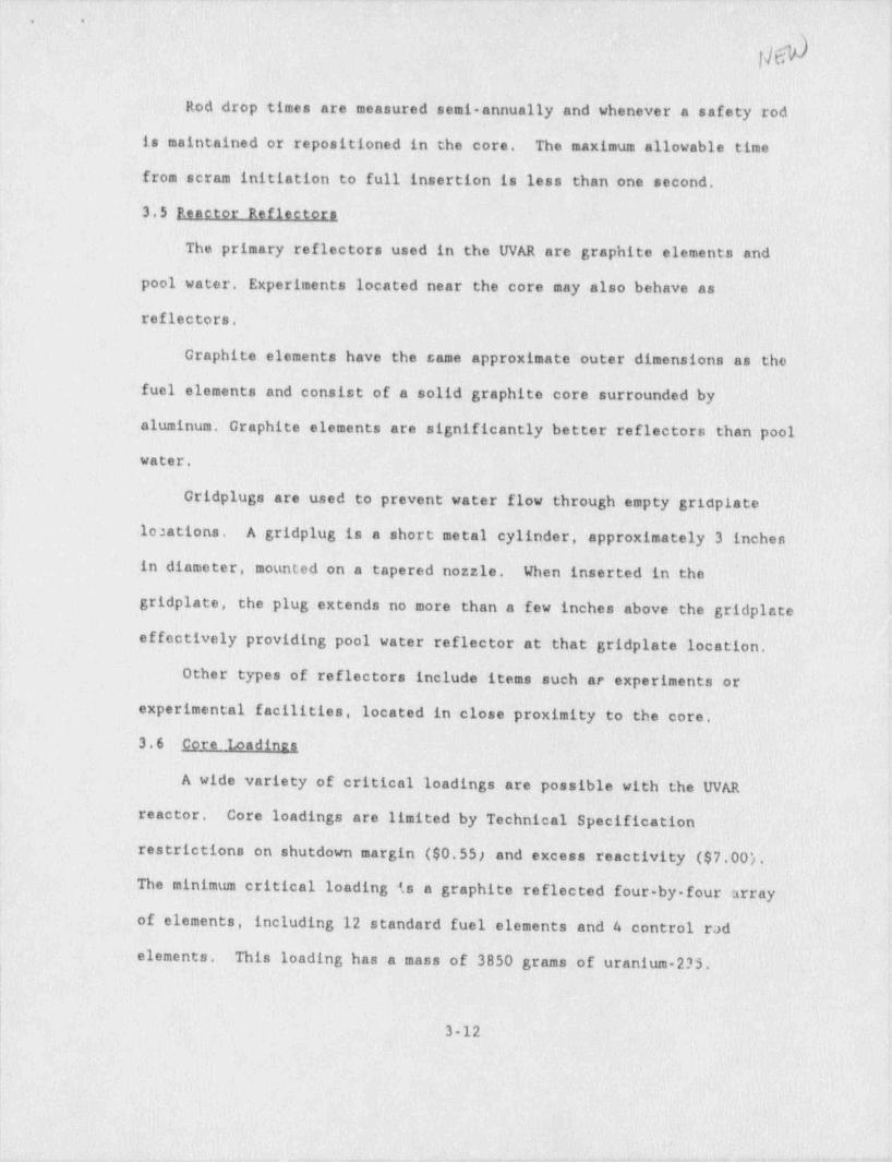
Table 3.1 Reactor Data for LEU Cores ;
I. Typical 4-by-4 acd 4-by-5 Core Parameters |
4 by 4 Core 4-by-5 CoreParameter Confituration Confinuration
1. Core Dimensionsa) Active height 23.3 inch 23.3 inchb) Width 12.6 inch 12.6 inchc) Length 12.0 inch 15.0 inch ,
-
3d) Volume 3,520 inch 4,400 inch 3 !
2. Number of Elementsa) Standard I? 16b) Control 4 4
3. Mass U 235 3.85 kg 4.95 kg
4. Metal-to Water Ratio(by volume) 0.70 0.74
II. Fuel Element-Parameters
Parametit Value
1. Outer Dimensionsa) Height 34.4 inchb) Width 3.14c) Length 3.00
2. Water Gap 0.092 inch
3. Standard ElementNumber of Fuel Plates l,
- Number of Side Plates 2_Uy235 Content 12.5 gram;_
- Metal-to Water Ratio 0.76(by volume)
4, Control Element- Number of Fuel! Plates 11- Number of Side Plates 2
Number of Cuide Plates 2-
- U,,235 Content 6.25 gram-Metal-to-Water Ratio 0.52-
5. Partial Element- Number of Fuel Plates 11- Number of Side Plates 2- Number of " Dummy" Plates fil- U-235-Content J5.li. gramj- Metal-to-Water-Ratio 0.76
.
|
3-17
||
, - - . . . .- - - ~ . - , -. . _ - .
1. .
-
i
f)$
Table 3.1 -Reactor Dataffor LEU Cores'-
iI. . Typical 4-by-4 and-4-by 5 Core Parameters- !
<
h14 by 4 Core 4 by 5 Core- i
Parameter Confiauration Configuration
1. ~ Core Dimensions._23.3 inch. 23.3 inch
'
- a) Active height_
b) Width 12.6' inch- 12.6 inch- >
c) Length 12.0 inch- -15.0-inch'.d) Volume. 3,520 inch 3 '4,400 inch 3 ,,
2. Number of Elementsa) Standard 12 :16-b) Control 4 4
-"
3. Mass U-235 ~3.85 kg 4.95 kg'
4. Metal to-Water Ratio(by volume) ,0.70 0.74
II. Fuel'ElementLP*rameters
Parameter yslue
1. Outer. Dimensionsa) Height. 3474 inchb) Width 3.14-c) Length 3.- 00 ' '
2| , Water Gap 0.092 incht
;
3. Standard Element- Number of Fuel Plates 22;
- Number'of Side Plates 2 j- U-235 Content / Fuel-Plate- 12.5! gram-- Metal-to-Water Ratio' O 76
;
(by volume).
>
4 Control Element- Number of Fuel Plates- 11 1 '- Number of-Side Plates -? 1
',
- Number-of Cuide Plates- &
- U 235 Content / Fuel Plate 12.5 gram '
- Metal-to-Water Ratio- 0.521
5. 'P'artial-Element- Number of Fuel' Plates 'll'
- Number of Side Plates 2 j- Number of " Dummy": Plates 11- U-235 Content / Fuel Plate 12.5 gram- Metal to-Water Ratio 0.76 !
L 3-17
, = _ = . - - ,. . ..- - . , ,. . - ,

.
. .
>
2. Regulating Rod
a) Absorber Material Stainless Steelb) Dimensions ~ Same as Shim Safety (No grooves)c) Travel 24 in.d) Release None - does not drop on scrame) Typical Reactivity
Fully inserted $ 0.3 to S 0.5f) Typical Reactivity per in. $ 0.02g) Typical rate of Reactivity
increase in up travel (per- $ 0.01second)
VII. Feedback Coefficients (Reference (9))
1. Doppler Coeff ($/0C) 1.5 x 10⁻³
2. Void Coeff ($/% void)a) Uniform void (1 to 10% void) - 0.3
b) Local void (1 to 14% void) - 0.8
3. Moderator Coeff ($/0C) - 0,02
VIII. Kinetics Parameters (Reference- [9])1. Prompt Neutron Lifetime 53 to 67 microsecs
2. Effective Delayed Neutron 0.0074Fractions
3-191
|
|
|
I-l'
- -

._ . . _ . _ . - . . . , ..-. _ _ _ . . . . . . , . _ . . . ... .. _ . . _ _
, -. :<.
.
2. Regulating Rod-|
a) Absorber Material' Stainless-Steelb) Dimensions Same as Shim Safety (No-grooves) .
,
Jjc) Travel 24'in,
d) Release None does'not drop on scrame) Typical Reactivity
Fully inserted- $ 0.3 to-$'1.0. f) Typical Reactivity per in.. $ 0.01 to S 0.04 ig) Typical rate of. Reactivity
increase in.up travel (per. .$ 0.004 to $ 0.02 =fsecond)
VII. Feedback Coefficients (Reference (9])7'1. Doppler Coeff ($/ C) - 1.5 x_10-3
s2. Void Coeff ($/t void) .
,
a)-Uniform void (1 to 10% void) - 0.3~b). Local void (1 to'14% void) - 0.8 '
3 ~. Moderator Coeff ($/0C)' - 0.02
VIII.. Kinetics Parameters -(Reference - [9])1. Prompt Neutron-1.ifetime 53 to 67 microsecs
2. Effective: Delayed Neutron 0.0074Fractions
a
'I
.i
.
.
- 3 '- 19
I
'1
. - ,- . 4 _. _ , - . ..n, _ . _ - . _ u

- - - -. . . - - . - - - . .
.- .._.
,
OL D'
The Intermediate Range instrumentation receives its input from a
compensated ion chamber and provides indication of power level and: period !
over seven decades. Both power level and period measurement-are
displayed on the reactor console and power level indication 11s repeated'
on a chart. This instrument provides protection-against a-too rapid.
_Eigure- P N:1 car Inetesentatie . period by scramming the reactor if
the period is too short.-1
The Power Range instrumentation contains two cornpletely independent -!-
-
.
.
.
power range' channels, each of which indicate reactor power over-ae range- .
of 0 to 150 percent. Each channel is supplied with c.n input _ signal from .
an independent uncompensated ion chamber.- The output from these channels
are displayed by separate meters on the reactor console. Each of theseJ,
ichannels provides independent-scram protection from high reactor power. '
There is a range switch to select full power; indication of:2MW-when in
forced cooling or 200 kW when'in natural convection.. -i
Indication of reactor power is also provided-by a linear. power,
instrument over 9 decades of reactor power through a' range' selector-
switch. This instrument receives its input from a compensated ion
chamber and its output is displayed by a meter and a chart on the reactor
console.. The-linear power. channel recorder indication.also. serves as.the
sensing element for the automatic control system (see Section 3.12) which* operates the reBulating rod to maintain a set. power level. -a
In addition to the|above instrumentation,-the following indications
are provided for comparative observations of reactor power, 1
An ionization charaber, located on the ground floor in the heat -?1exchan6er. room (adjecent to the primary piping),)is used to detect gamma- '
u;1'
..
3-23

_ - ._. . .
. .-..
&The Intermediate Range instrwnentation receives its input from a
compensated ion chamber and provides indication of power level and period1over seven decades. Both power level and period measurement arei
displayed on the reactor console and power l'evel indication is-repeated
on a. chart. This instrument provides protection against a too rapid
period by scramming the reactor if the perfod is less than~3| seconds.
The' scram is accompanied by an audible alarm.
The Power Range instrumentation contains two completely independent. !
power range channels, each of which-indicate reactor power over a range -!
of 0 to 150 percent. Each channel is supplied with an input-signal from--i
an independent uncompensated ion chamber. The output;from'these channels !
. are displayed by separate meters on_the: reactor console. Each of these.
channels provides independent scram protection from high' reactor power.
There is a range switch to select full power indication of 2tN when in
. forced cooling or 200 kW when in natural convection.-;
Indication of. reactor power-is also provided by a linear power'
instrument over 9 decades of reactor power through a: range selector
switch. This instrument receives.its-input from a compensated ion ~r
chamber and its output is displayed by a meter and:a chart on the reactorl'
'
console.- The linear power channel recorder indication alsoiserves as.the
sensing-element for the. automatic control system (see Section 3.12) which4
*
operates the regulating rodLto maintain a set power level.
In' addition to the above. instrumentation, the following indications '
are provided for comparative-observations of reactor power.-,
An ionization chamber, located on the ground floor in the heat
exchanger room (adjacent to -the primary piping), .ie used to detect gamma-
3-23
,
'
. .
OL D'
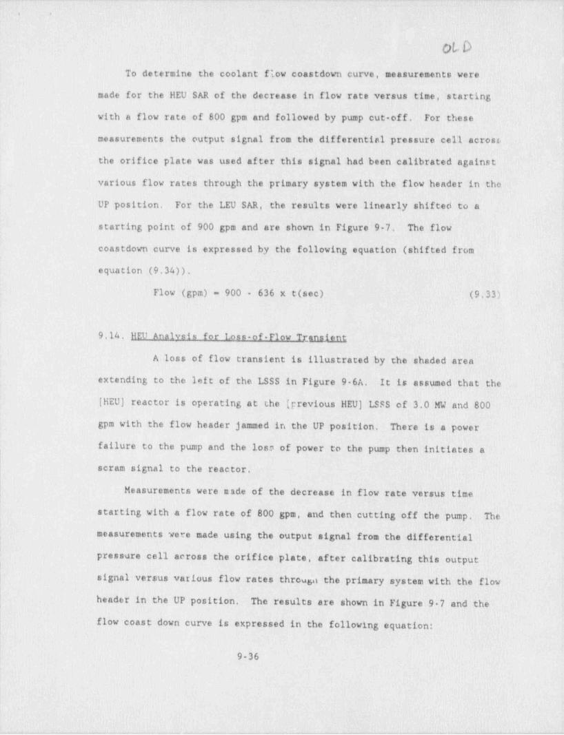
To determine the coolant flow coastdown curve, measurements were
made for the HEU SAR of the decrease-in flow rate versus time, starting
with a flow rate of 800 gpm and followed by pump cut-off. For these
measurements the output signal from the differential pressure cell acrost,
the orifice plate was used after this signal had been calibrated against
various flow rates through the primary system with the flow header in the
UP position. For the LEU SAR, the results were linearly shifted to a
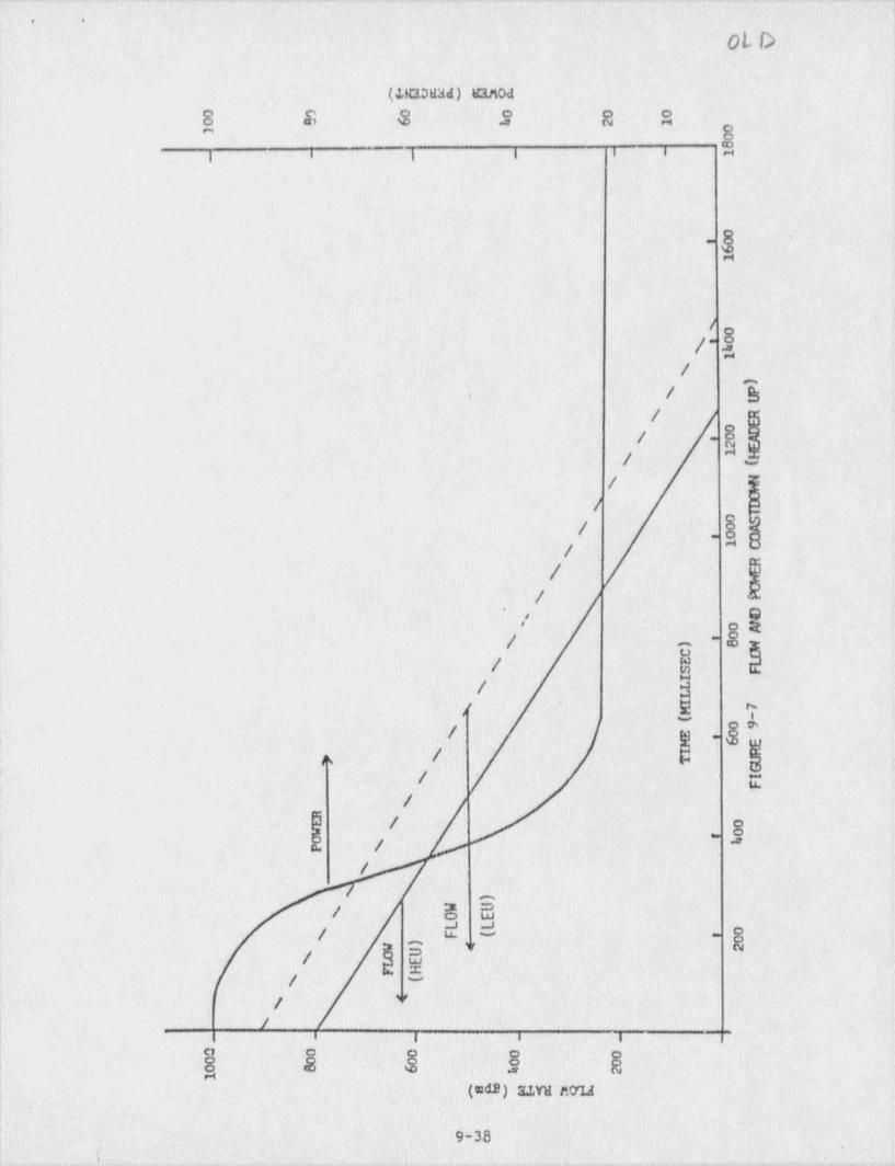
starting point of 900 gpm and are shown in Figure 9 7. The flow
coastdown curve is expressed by the following equation (shifted from
equation (9.34)).
Flow (gpm) - 900 - 636 x t(sec) (9.33)
9.14. HEU Analysis for Loss-of-Flow Transient
A-loss of flow transient is illustrated by the shaded _ area
extending to the left of the LSSS in Figure 9 6A. It is assumed that the
[HEU) reactor is operating at the (previous HEU) LSSS of 3.0.MW and 800
gpm with the flow header jammed in the UP position. There is a power
failure to the pump and the loss of power to the pump then initiates a
scram signal to the reactor.
Measurements were nade of the decrease in flow rate versus' time
starting with a flow rate of 800 gpm, and then cutting off the' pump. The
,- measurements were made using the output signal from the differential|'
pressure cell across the orifice plate, after calibrating this output!
signal versus various flow rat'es throurja the primary system with the flow
header in the UP position. The results are shown in Figure 1 9 7 and the
flow coast down curve is expressed in the following equation:
9-36
- _ _ . _ _ . . _ . _ . _ _ . . .
>
, . . .
f) Elk):
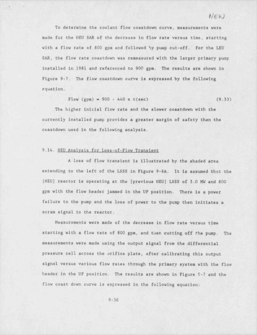
To-determine the~ coolant flow-coastdown curve, measurements were
made for the llEU SAR of the decrease'in flow rate versus time, startingy. - i
with a flow rate,of.800 gpm and~followed by pump cut-off.- For the LEU-
SAR, the flow rate coastdown was remeasured with th'e larger primary pumpj
installed in 1981 and referenced to 900.gpm. = The results are shown ini
Figure 9-7; .The flow-coastdown curve.-is expressed by the following- |
equation, j
- Flow (gpm) - 900 440 x t(sec)- ~(9,33).,;-- . . - , .
..
The higher initial flow rate.and the slower.coastdown with the: q
;
currently installed pump provides a greater margin of safety than the~ ,I
coastdown used:in the fo11'owing analysis,
9,14, llEU Analysis - for- Loss-of-Flow Transient
A loss of flow transient-is illustrated by the' shaded area-
extending to' the lef t of the LSSS -in' Figure 9 6A.- It is assumed that the
(IIEU) reactor-is operating at.the-[ previous llEU) LSSSJof;3.0 MW and 800 J
gpm with-the flow-header jammed in the;UP-position.-- There is a power;
failure to the pump and the loss of power to the pump then initiatesta - '
|scram signal.to the reactor. 1
,
'LHeasurements.were made of the decrease in flow = rate versus time =.
,
s
starting with a flow rate of 800 gpm,"and'then cutting off the pump.- The- '
Jmeasurements were made'using the output signal from the differentiali
pressure cell across the; orifice plate, after calibrating.this output'
. signal versus various flow rates through 'the primary system with the1 flow.1
Jheader?in the UP position.. The results are shown in: Figure.-9-7-and the=
,
1
l flow coast down curve is expressed in the following equation:,1
t
9-36
!
.?
t
4 r + , s,-. s -, - , . ., .9-..r.,,<.m v w - , , ,
-._a,_ 4 A. 4-. 4 e, s. ,m .w a p 2 A - &
Y
'.'
u souaa> uanoa
$ E 8- S S o ;
8- !
m I
I i i i i i . l
g ._
-
/
$/~
-/
' - - / 3-/
/ E.-
"/
/
/
| $.*
/
- / @/ R i
* - ,' O-
8[/-
. id-
/ >gc /; w ..
f*
3''/ t! --
/ pis '
/-- _.u.
.j-
,!- ,
/
-/
= 3/ :3' . *j
.o./ = u. - -- ~
. v. g; . ;
f {(
- / -- 5
. 1
/ .v,
_
\ /' a , ,
d o' 8 'a
Oh $_ - "
("d2) s.tw nou -
\ 9-38,
'. , ,, , .,
* +'-- . . .. . . , ,

.. . . 7. _. .
. . .
1 (11G3N' d )' i EIMod -. ~:3 ~-
O-- O
'
gm ' %: :- j.-'' --- O :. O-
N: H,. O.
.
u ,
b. [| | g
-[ H
/ :
/. ._ s .
-L.
') .
/.a
8< .- i'
-,.
/ M -,
'
t
m. -?.
: /. .s J,i>
.!- o.- - = . O cg 7.
,
;j ~
.
1
/ f_-,O :
,' o O
./-.
d' , j
!)
/ g.-1
Og-. ,.
/' ' } h ,
e./ y .
. ,
Oa'.
|-'
n
,/
j/ O'- |
O-. :"
/a
. /. , - d
. ,o. w-
} :f- 8:s
> -g__._ v
./, 'e u.
= >-
' . ~ ~ ._
,'l- ga- O .I
-
o o ,
N -@ - O.-
va>unam9-38- M
.i.i
- +.,-.,,---,-<.w,e, --o. - ,- - b _ w n ,- - - - - , n -, , - , - . - - - , s

._. . .
i. .
~!
' 9
Question #4:
In reference to SAR page 3 21, Section 3.10, Nuclear Regulatory Commission(NRC) Safety Evaluation Reports (SERS) for specific facilities are not generallyor directly applicable to support statements and conclusions for other facilitiesTherefore, provide your independent assessment of fission product inventory
~
(including plutcaium) for the LEU fuel and demonstrate direct applicability toany referenced document. Include consideration of power level and distribution,fuel configuration and composition, fuel rotation plans, and other-relevantfactors,
. . ~ . _ .
f
I
f
|- 1
1
-l!|
|
I
i
~ . - - - ,

_ . _ _
. .
I
Response to NRC request for additional information -Question 4: UVA's LEU /HEU fission product inventory assessment.
In regards to section 3.10, pg.3 21 of the LEU SAR, an analysis of the fission-product inventory has been performed and has confirmed the results ofWorchester Poly. Inst's. Safety Evaluation Report (LEU -SAR Reference 11) .
Using Sandia.ORICEN, a well documented code which calculates a detailed =isotopic composition as a function of time-in nuclear reactor fuel irradiation-problems. uranium fuel concentrations, power, and time were-input to determinethe nuclide concentrations due to irradiation of the fuel.
The code is a point code (no spatial dependence) and therefore, the coregeometry is not a factor in the calculation. The calculations vere done usingthe fuel concentration per element and an average power per element. based on:atotal core power of 2 MW. (The core is assumed to contain 16 normal elementsand 4 control rod elements), Two irradiation times (120 days and 720 days,- .both 2MW, 24hr/ day) were used for comparing the LEU and HEU cores. 'Also a 1440day cycle (24hr/ day,2MW), far exceeding the length of time an element would bein the core, was used for evaluating the maximum fission product build-up in'the LEU core.
The results of.the code showed that fission product inventories, excluding-
; actinides, were similar (within grams) between HEU and LEU cores, Whenactivities of fission product elements (708 nuclides are listed in the. code-output, comprising 41 elements) are compared, following a 120 day decay periodless than a 10% difference is noted and the activity of the- LEU core is lessthan the HEU core. -U235 burn-up amounts and core flux levels were looked at.and both fell within 10% of the expected or known values.
The major actinide produced is plutonium and constitutes about 90% lof theactinide concentration. This concentration is higher, by about a factor of 10,in LEU fuel compared to HEU fuel. This is expected because of the largeincrease in.U238 when going from HEU (12g/elem.) to LEU.(1100g/elem.).However, even after a 1440 day continuous run at 2 MW, tho'Pu concentration inLEU fuel is less than 15 grams /elen. This is.still not a significant amount,representing < 2% of the Uranium inventory. Only plutonium deviates >.0.1g/ element between HEU and . LEU cores.
INVENTORY PER ELFRREI 120 DAY 720 DAY 1440 DAY.
M M M. -M MFISSION PRODUCT' ACTIVITY: 5.23 ESC 1 5.26ESCi 4.86E5Ci 4.89E5Ci 4.96E5Ci
FISSION PRODUCT ACTIVITY: 8.53E3Ci 8.52E3Ci 1.65E4Ci -1.62E4Ci- =1.93E4Ci(Irred. + 120 day decay)
Pu. + FISSION PRODUCTS: 14.04g 14.93g 82.68g 89.20g 117.6g
TOTAL PLUTONIUM: 0.09g 0.93g 0.35g 5.53g -11.9g
TOTAL' URANIUM: 164.70g 1377.00g 95.07g 1302.00g 1212.0g
a. - _ ,

. - - .. . . -.
.= .
To summarize, the-fission product inventory will not significantly differbetween HEU and LEU cores. Plutonium production while higher in the LEU core,is less than 2% of the Uraniwn inventory. Since the fission product inventory
~
distribution does not significantly-differ, the itopact caused by the fuelcl.ange on the operatiots of the facility is negligible and no further analysisof its emergency plan is warranted.
-
,
s
!
l
|
!
1
. - - , - .. . ._. . _ . - -

4 4
Question #5:
The proposed Technical Specificacions have a safety limit based on .temperature of fuel cladding. This is inconsistent with the current TechnicalSpecifications, ANSI /ANS 15.1, and 10 CFR 50.36. These-documents define andestablish safety limits as process variables.-
,
i
a) Therefore, provide safety limits consistent with these documents, that: is,process variables, such aa, reactor coolant flow rate, reactor thermal power
.level, pool water level and reactor coolant-inlet temperature. 'l
b) Also, provide similar safety limits for the' natural circulation mode.of'operation,
k
t

. ,. _ .~. .. ._ _ _ ___ . . _
. _ ,
, s. ;f .|
l
11
2.0. SAFETY LIMIT AND LIMITING SAFETY SYSTEM SETTINGSn
,
2.1. Safety Limitst
3
2.1.1 Safety Limits'in Forced Convection Mods of Operation- '
Apolicability: .This~ specification appliesLto the_ _. interrelated variables associated with core-thermal-and 4
hydraulic performance in the forced convection mode of-
operation. These variables.are:-
P'- Reactor thermal-powerW;- Reactor coolant flow rate-
T1 Reactor coolant. inlet (temperatureL_- Height of-water above the core
Obiective: The objective is to ensure .that thej integrity of r~
the fuel clad is maintained.._
Soecifications: In the forced convection mode;of: operation: ,
i1) The pool water level shall not be less than-19-ftabove the top'of the-ecore.~
-
-
,
2) .The reactor coolant inlet temperature'shall not-bogreater than 111'F.
3) The true value of reactor. coolant flow shall not bebelow.575 gpm.
4) The combination of true1 values of reactor core power { _;cnd reactor coolant flow:sball be below the 11nedefined'by: .
P- .241+;(4.5 j 10-3 W. W) ' for W V 575'P - O'Lfor W <1575
P in MW,- W in gpm
Theallowed) region-of' operation _isshown'byithe =4
unshaded region of Figure 12.1.
Basis: ;Above 575 gpm in thelregion of_ full power operation..the criterion used to establish-the safety limit-wasia' .
burnoutfratio of.1.49: including the_ worst variation'in the,
manufacturer's-tolerance and. specification,_ hot channel ~
,
factors and other appropriatecuncertainties. The1 analysis iis given in the LEU SAR.
-Below 575 gpm buoyancy forces competing 1with' forced-:--
convection mayflead to flow-instabilities in some-of the- '
channels and is therefcre r.ot .s11 owed. 'The' analysis of the-,
-
loss of flow transient shows that; during the ? transition -fromforced convection to natural: convection-following a'lossLof:flow atid: reactor scram that the-fuel temperature is well.
below the, temperature.at.whichtfuel clad damage could occur.>
: l. 4
I
, , _ . . , _ . -_, . . . . - - , . ~ - - - * - - - -+ ~ +~ + '~"' ' -"" *

e i
!
i
i.8 :. i*
i!
$.
'O jO '
i~D~,;
#j
!
)
oO
* *4, >e< o
MNd .I
.o .-
>e44J
8 E. 8- N >e-8 - O Q
o= Q ,
CE i
. 'o-
/W*-
W U.W 44
O ~ . 10 0. hN . 4
'N > '.cO' 4J
M .eeN 3.4J traQ +J(C 1 *e4
O e* EO O 'e4CO *.
Q.O e.1a
AW 4JO WM- %U- 8040 to@
O 08.O.
cM
e
N
WW
/ ..O- NO- .et
4k
..OoN
.I
i l l I l |I I i i i i ico '.s D in 4 'm N M o
MN 'd 'aanod IemaaqI,aoaovou
to *
_-
-.
.- . , -
6
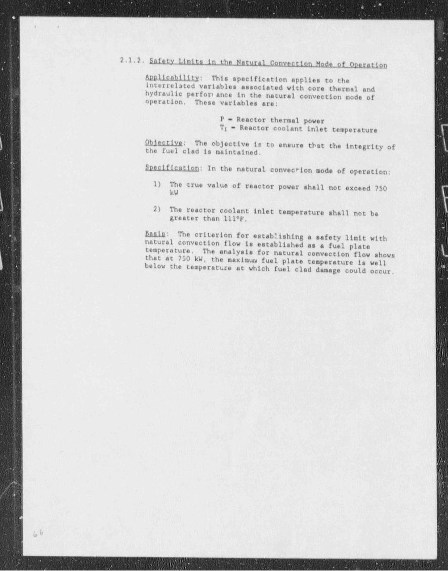
2.1.2, Safety Limits in the Natural Convection Mode of Operation-!
Anpilcability: -Thisispecification applies to the -jinterrelated variables. associated.with core thermaliandi 1
. hydraulic perforr.ance in the natural convection mode of!operation. JThese_variablesfare:: j
P - Reactor thermal power;T - Reactor coolant inlet temperature
_
Objective: The objective is to ensure =tbst'the integrityLofthe fuel--clad is maintained.
.
Soecification:-In the natural convection' mode of operation:. !
1) The true value ofireactor power'shall-not exceed' 750 '
kW
2) The reactor coolant inlet temperature'shall not be-greater than 111*F;
Basts: .The criterion.for establishing a safety. limit withinatural convection flow-la established as a fuel: plate
-
temperature. ''Dae analysis- for natural convection flow shows'that at 750 kW, the maximum fuel plate temperature is well_below the temperature'at which: fuel clad damage could_ occur,
.
!1
'
-
,
at
!
i
3 -
: -}
# - 's-
' &~ f -
3
|- i. .-
2.1.3 Safety Limit for the Transition from torced to NaturalConvection Mode of Oneration
Annlicability: This specification applies-to the conditionwhen the-reactor is in transition from forced convectionflow to natural convection flow.
)1Objective: The objective is to ensure that the integrity of '
the fuel clad is maintained.
Specification: The current to the control rod magnets mustbe off when the reactor is making a transition from forcedto natural convection.
Basis: The safety analysis of the loss of coolant transientdemonstrates that the fuel plate temperature is maintainedwell below the temperature at which fuel clad damage couldoccue during the transition from -forced downflow throughflow reversal to the establishment of natural convectionprovided that the loss-of flow transient is accompanied by ascram,
a

. .
Definition
Forced Convection Mode: The reactor is in the Forced convection Mode when theflow header is up and the primary pump is operating.
Natural Convection Hoda: The reactor is in the Natural Convection Mode whenthe flow through the core is maintained by the buoyancy forces associated withthe water being heated by the reactor.
>
l
I
1
,
- _ _

v>
. .
|
Question a6:
Implicit in the analysis'of the short period transient in SAR Section 9.12for the llEU core is that-the maximtun acciden*,a1 reactivity addition will result
!in a reactor period of about three seconds. Is this valid for the LEU core?Provido justification and analyses for this assessment.
!
l
!
|,
;
!
,1
i
?
,
I
-- - >
|

s. .
1
Response to question 6
It is not implicit in the analysis of the short period transient that i
the maximum reactivity addition will result in a 3 second period. What is !implied and clearly stated is that the reactor will scram when the period i
reaches 3 seconds during a continuous reactivity insertion accident
The limiting conditions on a short period transient are that the powergoes through 3.45 MW with a period of essontially 3 seconds under the !
!condition of no temperature feedback. This condition is not sensitive to the |actual reactivity insertion rate that could be caused by a continuous rod '
withdrawal accident. A continuous rod withdrawal accident will result in aperiod that starts at infinity at the beginning of the accident and getshorter as the transient develops until it reaches, the scram setpoint of 3seconds or the power scram setpoint at 3.45 MW.
i
There exists a set of initiai' conditions of power and reactivityinsertian rate that will give a period slightly longer than 3 seconds at thepower scram setpoint-of 3.45 MW. Large r reactivity insertion rateh at e given $
power will cause the reactor to scram on a short period signal at less than j3.45 MW thereby limiting the peak power of the transient. Lower reactivityinsertion rates will cause the reactor to scram on a high power signal at alonger period than 3 seconds thereby limiting the peak power of the transient. |
!
IFor example, with a postulated reactivity insertion rate of $0.013 per
second, the starting power to cross 3.45 MW at 3 seconds is 19 kW (assuming NO |ltemperature feedback). If the power is less than 19 kW at the start of the itransient, the reactor will scram on period at a lower e wer than 3.45 MW.
the power is greater than 19 kW at the start of the trant. lent, Ifthe reactorwill scram at 3.45 MW at a longer period than 3 seconds.
reactivity insertion rate is different from $0.013 per second, a different |If a postulated
Istarting power must be postulated to yield the limiting case,f
The actual starting conditions causing the limiting continuousreactivity insertion transient are not important if temperature feedback is jignored and the reactivity addition does not cause the reactor to go prompt i
critical before the instruments can respond. !The resulting transient period!and power at the time a scram occurs defines-the limiting conditions for the
-
accident. |
The controlling function for the peak power during the transient isthe delay time to insert the rods far enough to stop the transient.- This is-conservatively taken as 350 ms (50 ma magnet release plus 300 ms for the rods |to drop 5 inches). '
3.45 MW that yields the maximum power for the transient of 3.88 MW,It is this time along with a 3 second period at a power of,
;
l
u1
|1
|
_ _
. __

.. _ .- _ - .-. _ _ _.__._. _ - _..._.. _ __ . _ -- _.__._ _ _ _ .._..__.... _ _._._ _ _ _ _ .__._.
Iy .: . ;
i
l, '
iJ
I Question #7;4
j in order to avoid confusion, the Technical Specification changes not related .
4
: to LEU conversion -should be removed from this application. and if desired *
' submitted separately..
;
4 I,'
i; !4 .,
'i
e
a
5, d,
.
h
!
I
. iN
4
a
'?
f1
.
E
'
p
fi. .
.J
:.!
..
.
I,
i
j
,.
|| '|| |
.]
_ ._
,f -
T r
N'
- - - - - - _ _ _ - - _ _ - _
'

-. - __ -- - . . - . . - - - . .
[. .
;_
1
UVAR Tech. Spec. Changes Related to LEU Conversion
1) Changes to "1.0 DEFINITIONS"
a) A definition for " Forced conventhut,J1942" has been,.
included. This was necetoary with respect to TS2.1.1. '
b) A definition for " Natural Convectjon Mode" has beenincluded. This was necessary with respect to Basis toTS2.1.1, and TS2.1.2.
c) In the definition of Reactivity Limits, " core activity" i
has been corrected to " core reactivity". The values"0.05% Ak/k" has been changed to 0.07$, using a " beta-bar" conversion unit appropriate to an HEU core.Reactivity values expressed in $ units are " beta-barand fuel type independent.
2) Changes to TS 2.1.1a) A true minimum value of reactor coolant flow' (Specification 3) for a LEU core has been specified as |
575 gpm.b) For allowed reactor coolant flow above the TS minimum
limit, the region for allowed. combination of Power andFlow has been established (Specification 4) by afunction.
c) The basis for this TS has been re-worded, as necessary,to explain and justify this TS for LEU cores.,
d) Figure 2.1 has been re-done to conform to TS2.1.1 ,
requirements.
3) Changes to TS 2.1.2.
a) The TS limits are unchanged, but there are some formatchanges and some wording changes. In two locations" natural convection mode flow" was changed (as a.
,
correction) to " natural convection mode". *
b) The single specification for P and Ti has been (as acorrection) indicated as two separate specifications1&2.
c) Superfluous words have been dropped from the text ofthe (HEU) basia to TS2.1.2
3
4) Addition of TS 2.1.3 covers the transition from forced tonatural convection mode of. operation.
5) Changes to TS 2.2a) To the " Applicability" section, the symbols for the
parameters were dropped (as unnecessary), and thereactor period was an-added parameter to the list'of-those reactor parameters subject to LSSS.
b) The reactor coolant flow rate LSSS was increased from800 gpm(min) to 900 gpm(min),'as required by LEU SAR.
c) .The reactor period LSSS was- set. at 3.3 sec(min) _(seeLEU SAR analysis)~for both-forced and naturalconvection modes of operation.
d) The wording in the " Bases" was expanded to address
1
.- _ - _ _ _ _ _ -
. - . . --
. .
(UVAR TS Changes Related to LEU Conversion, page 2)
separately the forced and natural convection modes ofoperation. The lack of an LSSS for natural convection wasclarified with our excerpt from the analysis in the LEU SAR.
,
6) Changes to TS 3.1a) Reactivity values previously expressed in units of %
Ak/k have been converted to $(dollars). This is thecase for 3.1. (1) , /2),(3),(4) and (5). These samechanges are carried through to the " Bases". (See also1.c) and 11.a) in this reference).
b) The paragraphs in the old " Bases" have been reordered.The next to last paragraph in the previous TS hasbecome a " preamble", while the other individualparagraphs have been numbered.
7) Changes to TS 3.2a) The changes are very minor, basically changing
reference from the "old" SAR to the LEU SAR.
8) Changes to Table 3.1-a) The " Set Point" for Primary coolant flow has been
increased to 900 gpm(min), for compatibility _with LEUSAR analysis and TS2.2.(1).-
b) The Reactor Period " Set Point" has been changed from 3sec(min) to 3.3 sec(min), for compatibility with LEUSAR analysis and TS 2.2(1) and TS 2.2(2).
c) Statements at bcttom of table relevant TS 3.3 (and notto the table) have been_ moved to another page.
!; 9) Change to TS 3.4'
a) In the " Specification" to TS 3.4.1, consideration isgiven to the fact that a~beamport may not be vented to
| the atmosphere. In other words, a closed system may bein operation. The change in wording of the Basis makesreference-to analysis in the " LEU SAR."
b) The change in wording of the " Basis" for TS3.4.2 makesreference to analysis in the " LEU SAR."-
10) Change to TS 3.5| a) The change in wording;of thel" Bases" for TS 3.5 makes
reference to analysis in_the " LEU SAR."
11) Changes _tc TS 3.6a) Because " beta-bar" varies somewhat with fuel type,
reactivity values quoted throughout TS were convertedusing an acceptable HEU " beta-bar" value , from % Ak/kto S. . Reactivity values expressed.in $ units are
! " beta bar" and hence fuel-type independent. Therefore,i the numbers used in 3.6.(2), (3), (4), -(5) and in thel " Bases"_were to accommodate the change in reactivity.| units. Similarly, reactivity values throughout TS were'
likewise converted.

-- . _-. -. _ - _ ._ .. . __. - . -
|. o1
I
(UVAR TS Changes Related to LEU Conversion, page 3)
12) Changes to Bases to TS 3.7a) Two References to the SAR were changed to "the LEU
SAR."
13) Change to Bases of TS 3.9a) The editorial change was to replace the reference to
the (old) "SAR" with one to "the LEU SAR.",
14) Change to Bar,es of TS 3.10a) The editorial change was to replace the references to
the (old) "SAR" with ones to the " LEU SAR". y
15) Change to Bases of TS 4.3a) The editorial change was to replace the references to
the (old) "SAR" with ones to the " LEU SAR." i.
16) Former TS 4.8 applying to Reactor Fuel Dose Measurements has ;
been eliminated because it should not be required for LEUfuel.
17) New TS 4.8 was formerly TS4.9 and is renumbered because oldTS4.8 was eliminated with the change to LEU [see 16) above). |
18) Change to TS 5.1a) The change from HEU to 30 is accounted for with a very s
general specification which will permit greaterflexibility by the licensee and NRe, in the-future, ifrequired.
19) Change to TS 5.2a) Editorial change made to HaJaa changed reference to
" LEU SAR".
20) Change to TS 6.4.2(4)a) The reactivity (old) value in % Ak/k has been converted
to $ unit.
m
i
t
____._.m_ . . _ ____________m _______._m_.________..__._ _ _ _ . - _ _ _ _ _ . . . - _ _ . _ . _ _ _ _ _ _ _ . _ . . _ _ _ . _ _ _ _ _ _ _ . _ _ _ . _ _ _ _ _ _ _ . _ _ _ . . _ _ _ . . _ _ _ _ _ _ _ . _ _ _ _ _ _ _ _ . _ _ . _ _ _ . _ _ . _ . _ _ . _ . _ _ _ _ _ _

_ __ __ . _ _ _ _ _ _ _ _ _ . . . _ __ . _ _ __ . _ _ _ _
a O
,
j UVAR Tech. Spec. Changes HQT-Related to LEU Conversion
General
1) Format changes to the text of the UVAR (LEU) Technical i
specifications (TS) have been made, in that the pagenumeration has been changed to reflect (additional) text ,
inserted or deleted from the "old"-(HEU) Tech. Specs. A ,
tdecision was made to begin, whenever necessary, TS sectionsat the top of a page. Blank portions of a page carry thestatement "(rest of page intentionally 1 eft blank)". = Each
~
page carries the note'hUVAR Tech. Specs." in the upper righthand corner. The format changes result in Tech. Specs.which are easier to read and consult. U.Va. requesto that :
NRC adopt the UVAR LEU Technical Specifications as an entire *
" package." The reintionship with the Order-to Convert is- !
given in a separate write-up. Below are specific changas toTS not linked to LEU conversion.' !
Specific
1) The title page was changed to reflect the latest-date on (which the (LEU) Tech. Specs. were revised and approved by- t
UVa's RSC, that is, January 1991.
2) Table of contents page in the revised text lists the same o
topics, however the corresponding page numbers aredifferent. The exception to this is the dropping of TS'"4.8Reactor Fuel Dose Measurements.. 19", since LEU' fuel willnot be subject to self-protection requirements. Therefore,the " Primary Coolant Conditions" section was renumbered from"4.9" to "4.8".Section "6.2 Review and Audit" has been retitled "6.2Reactor Safety Committee".Section "6.3 Operating Procedures"-has been-renamed "6.3Standard Operating Procedures".
,
The letter size has been. reduced to accommodate all contents ,
of this table on a single page.-
3) Changes to "1.0 DEFINITIONS"a) The section header has been underlined.
.
b) In.the definition of Channel Calibration,_ the. phrase.
| " values of the parameter _that the channel measures"_has-| been-replaced by " input values." The change in wording
makes the definition clearer,
c) In the' definition of Experiment, "any apparatus..." and j_
"any incore..." have been changed to "an apparatus..."and "an incore...". The change in wording makes thedefinition clearer.
L d) In the definition:of-Excerimental-Fa'cility, the phrase"is any structure..." is changed to "is a
_.
structure...".- The change in wording makes thedefinition clearer.
e) In the definition of -Explosive Material, the phrase His
|
_
.w--'gqu -ep .wg-p y rwyig er - '* y- g.g ym ru ay -g ,9 9 -y g e w- -y 4e=* 4 -993 g y 9. w + , . * , ,_
'p.p+,i,, --,.9- e.g. wwTy

. _ - - . . - . . .-
f 9
1
; (TS Changes HQI related to conversion, pago 2)
any solid..." is changed to "is a solid...". The change inwording makes the definition clearer,f) In the definition of Iuoled Exoeriment, the phrase "is
any experimont..." has been changed to "is anexperiment...". In addition, it has been made clearthat traco level quantities of U-235, U-233 or Pu-239are exempted, as are reactor fuel elements, whether in-or out-of-core. The change in wording makes thedefinition clearer,
g) In the definition of Measured Value, the phrase" process variable" is changed to " parameter". Thechange in wording makes the definition clearnr.
h) A definition for " Reactor Staff" has been added. (seeTS 6.2.1).
1) In the definition of " Secured Experimont", "anyexperiment has been replaced by "an experiment", for-clarity.
j) In the definition of "Truo value", " process variable"has been replaced with " parameter." As in a previouscaso, use of " process variablo" has boon discontinued.
4) Table 3.2 has been relocated to a separate page, and textpertaining to TS3.3 has been relocated without change.
5) In TS 3.6.(5), "If any experiment" was changed to road "Ifan experiment". This continues the practice to ovaluatewhether "any" should be replaced with "an".
6) Changes made to TS 3.7(a) In TS3.7(1), "W" was replaced with " watt (W)".(b) In TS3.7 (1) (c) and TS3.7 (2) (b), the phrase " total
exposure of the experiment is not greater than theequivalent of 6 years continuous operation at.100W" wasreplaced by the more appropriate " calculated total
| energy produced by the experiment shall not exceed 600i W-years."
7 Change to Bases of TS3.8a) The editorial change made was to replace "ft" with
-
" foot".
8) Change to TS4.2a) In an editorial change to TS4.2(5), the phrase
"following items, which are listed in Table 3.1 are notconsidered to be reactor safety measuring channels" was
j -replaced with the more appropriate "abovei specifications (1 through 4) do not' apply to the
following reactor safety channels". s
b) The word "any" was dropped from the phrase " permit anylong-term drift", for it is redundant.
|
$
m_ . _ _ _ _ . _ _ _ _ . _ _ _ . _ . _ _ _ . _ _ _ _ _ _ . _ _ _ .

_ - .. .
. . --
'f' t
i
*
*(TS Changes HQT related to Conversion, page 3)
9) Changes to TS4.7a) In the "boolicability" section, the phrase "in the
ventilation line" has been inserted to conform with the '
system lay-out. *
3 b) Specification (1) has been reworded.while maintainingthe original intent. Accordingly, the-additionalstatement is made in the " Bases" that "use of airbornoeffluent monitor is required only if....beamports....is
; vented.... to the atmosphere." <
c) Reference has been updated to specify the LEU SAR-analysis.
10) Changes to TS4.0 (formerly TS4.9,-see LEU conversion basedTS Changes)a) In the Bases the references to sections "3.11" and
"4.9" have been updated to sections "3.10" and "4.7"resultant from editorial & conversion mandated changes.
11) Change to TS 5.3_
;
a) In the specification, the erroneous phrase..." for all!*
conditions of-moderation was replaced with the correct," assuming water moderation."
12) Changes to TS6.1.1..
a) Editorial changa was made to 6.1.2 replacing the phrase"of nuclear experience"'with "of experience in thenuclear field."
b) Editorial change was made to 6.1.3. (5) by replacing "Ahealth physicist" with "One'or more healthphysicists..."
13) Changes to TS6.2a) Editorial change was made to 6.2 by renaming it- -
(appropriately) " Reactor Safety Committee." Theprevious title " Review and Audit' is: actually a-
subsection to this TS. It is noted that this TS isabout the Reactor Safety Committee.
b) Editorial change was made to 6.2.1 by substitution-of-sentence "No more than two members.will be from theorganization responsible for Reactor Operations." with-"No more than one member will be from.the ReactorStaff." Note thatz a (new) definition for-Reactor Staff-has been added to-the DEFINITIONS section of TS.
c) TS6.2.3 has appropriately been renamed " Review and'Audit Functions"
14) Changes to TS6.3.-a) The title has been-renamed StandardLoperating-
procedures, to take into account. existence of certain-procedures which are Dgt SOP's.
b) TS6.3(7) has been defined, based on the sentence thatstated " Radiation control procedures shall be
f
,
..__._i______._.___-_______._____________.._ _ . _ _ _ _ _ _ _ _ _ _ _ _ . _ _ _ .

_ _ _ _ _ . - . . _ _ _ _ _ _ _ _ . _ _ _ _ _ . . _ _ _ . _ . . . . . _ . _ _ ._ . _ ....___._ ..
ji
;
l
I(TS Changes HQI related to Conversion, page 4) I
maintained and made available to all operations personnel."This sentence was then extinguished in the new TS.
15) Editorial changes to TS6.4a) In Title to 6.4.1, " Action" was changed to " Actions" &
"a" was changed to "the", in title and next sentenco.Throughout TS, the convention is "the" Safety Limit.
b) In TS6.4.1(2) and 6.4. 23) , the; incorrect reference tononexistent Section 6.7 was changed to 6.6. ,
16) Changes to TS6.5a) In TS6. 5.1(1) , " normal plant operation" records was
reworded " reactor operation-logbook", for precision.b) In TS6.5.1(2), " principal. maintenance activities" was
reworded " reactor systems maintenance records", forprecision.
c) In TS6.5.1(7), the qualifier "to and from the R-66 -;license" was added, for precision.
d) In TS6. 5. 2 (1) , the qualifier "from the Reactor-'
Facility" was added, for precision.e) In TS6.5.2(2), the qualifier "(radiological)" was
added, for precision.f) In TS6.5.2(4), the qualifier "at the Reactor-Facility"
was added, for precision.
17) Changes to TS 6.6a) In TS6.6.1(a),(b); 6. 5. 2 (a) , (b) , (c) ; ~ 6. 6. 3 (a) , (b) the
redundant word "any" was dropped.-b) In TS6.6.1(c) and 6. 6. 2 (c) the word "a" was changed to '
"the".c) In TS6. 6.1(3) (a) and (b), reference was changed to LEU
SAR.
1
l.
_-
. . _ _ . _ _ - _ _ _ . _ _ _ _ _ - _ _ _ _ _ _ _ - _