ins-t004 installation instructions - bilsteinlifts.com...toyota tacoma/hilux 05+ front coil overs...
TRANSCRIPT

INS-T004
IMPORTANT: Read all instructions thoroughly from start to finish before beginning the install. Check parts list and make sure all parts are included in the kit. If the instructions are not properly followed severe frame, driveline and or suspension damage may result. Check for frame and suspension damage prior to installation
This kit does not require welding. Do not weld on any component. Welding may void the warranty and/or cause the product to fail. If any parts are missing, or for tech
assistance; Contact King Off Road Racing Shocks. 714-530-8701
Installation Instructions (Page 1) Toyota Tacoma/Hilux 05+ Front Coil Overs
King Shocks 12472 Edison Way Garden Grove, CA 92841
714-530-8701 www.kingshocks.com
(1) With the vehicle on level ground, set the emergency brake and block the rear tires. Using a floor jack, raise the front end and support the frame rails with jack stands for safety. Then remove the front tires. NOTE: Never work under an unsupported vehicle.
(2) Remove the sway bar end link from the spindle. Remove the bolts holding the sway bar to the chassis.
(3) Remove the nuts from the upper and lower shock mounts but leave the bottom bolt in for now.
(2) (2)
(3) (3)

INS-T004
IMPORTANT: Read all instructions thoroughly from start to finish before beginning the install. Check parts list and make sure all parts are included in the kit. If the instructions are not properly followed severe frame, driveline and or suspension damage may result. Check for frame and suspension damage prior to installation
This kit does not require welding. Do not weld on any component. Welding may void the warranty and/or cause the product to fail. If any parts are missing, or for tech
assistance; Contact King Off Road Racing Shocks. 714-530-8701
Installation Instructions (Page 2) Toyota Tacoma/Hilux 05+ Front Coil Overs
King Shocks 12472 Edison Way Garden Grove, CA 92841
714-530-8701 www.kingshocks.com
(4) Remove the bolt holding the ABS line from the spindle. While holding the ABS line out of the way, remove the lower shock bolt and pull the factory shock out from the bottom. (5) Insert the new King Shock from below taking care not to damage the ABS line. Start the mounting bolts through the top shock mount into the top plate but don’t fully tighten them. Insert the rod end into the lower mount then tighten all the bolts.
(4) (4)
(4) (5)
(5)
(5)
INS-T004
IMPORTANT: Read all instructions thoroughly from start to finish before beginning the install. Check parts list and make sure all parts are included in the kit. If the instructions are not properly followed severe frame, driveline and or suspension damage may result. Check for frame and suspension damage prior to installation
This kit does not require welding. Do not weld on any component. Welding may void the warranty and/or cause the product to fail. If any parts are missing, or for tech
assistance; Contact King Off Road Racing Shocks. 714-530-8701
Installation Instructions (Page 3) Toyota Tacoma/Hilux 05+ Front Coil Overs
King Shocks 12472 Edison Way Garden Grove, CA 92841
714-530-8701 www.kingshocks.com
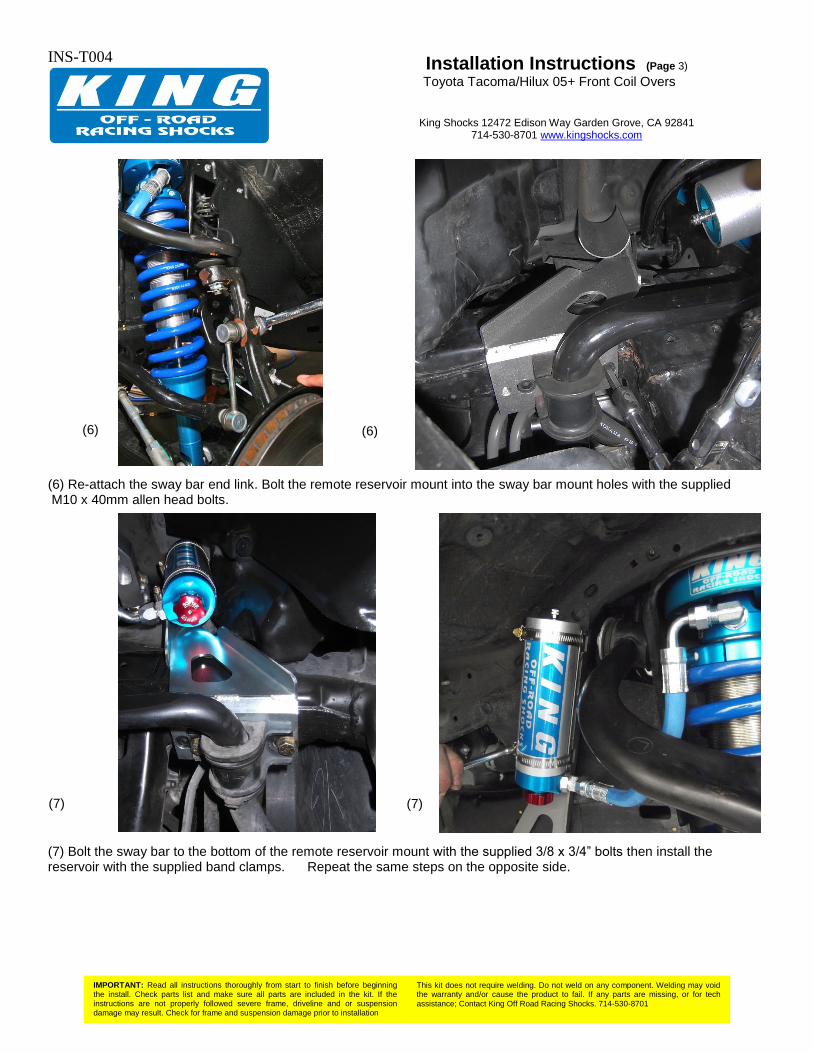
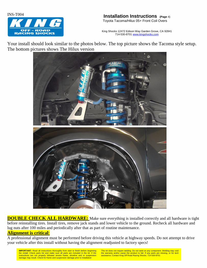
(6) Re-attach the sway bar end link. Bolt the remote reservoir mount into the sway bar mount holes with the supplied M10 x 40mm allen head bolts. (7) Bolt the sway bar to the bottom of the remote reservoir mount with the supplied 3/8 x 3/4” bolts then install the reservoir with the supplied band clamps. Repeat the same steps on the opposite side.
(6) (6)
(7) (7)
INS-T004
IMPORTANT: Read all instructions thoroughly from start to finish before beginning the install. Check parts list and make sure all parts are included in the kit. If the instructions are not properly followed severe frame, driveline and or suspension damage may result. Check for frame and suspension damage prior to installation
This kit does not require welding. Do not weld on any component. Welding may void the warranty and/or cause the product to fail. If any parts are missing, or for tech
assistance; Contact King Off Road Racing Shocks. 714-530-8701
Installation Instructions (Page 4) Toyota Tacoma/Hilux 05+ Front Coil Overs
King Shocks 12472 Edison Way Garden Grove, CA 92841
714-530-8701 www.kingshocks.com
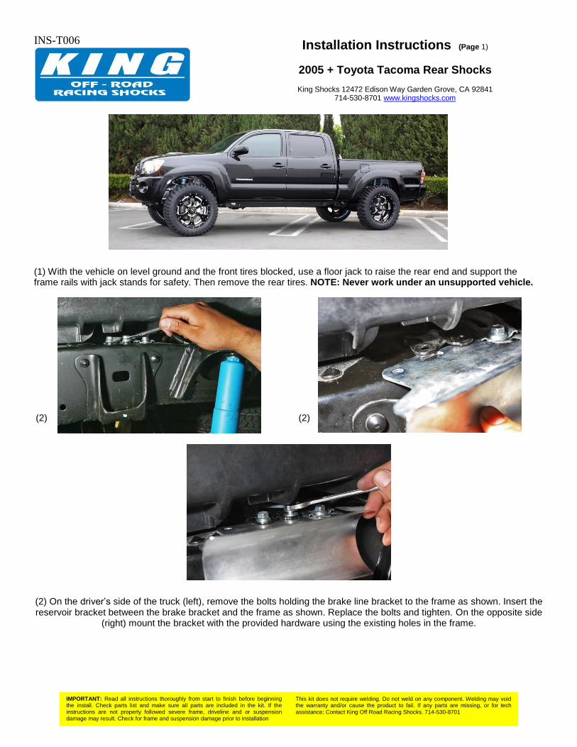
Your install should look similar to the photos below. The top picture shows the Tacoma style setup.
The bottom pictures shows The Hilux version
DOUBLE CHECK ALL HARDWARE: Make sure everything is installed correctly and all hardware is tight
before reinstalling tires. Install tires, remove jack stands and lower vehicle to the ground. Recheck all hardware and
lug nuts after 100 miles and periodically after that as part of routine maintenance.
Alignment is critical: A professional alignment must be performed before driving this vehicle at highway speeds. Do not attempt to drive
your vehicle after this install without having the alignment readjusted to factory specs!
INS-T006
IMPORTANT: Read all instructions thoroughly from start to finish before beginning the install. Check parts list and make sure all parts are included in the kit. If the instructions are not properly followed severe frame, driveline and or suspension damage may result. Check for frame and suspension damage prior to installation
This kit does not require welding. Do not weld on any component. Welding may void the warranty and/or cause the product to fail. If any parts are missing, or for tech
assistance; Contact King Off Road Racing Shocks. 714-530-8701
Installation Instructions (Page 1)
2005 + Toyota Tacoma Rear Shocks
King Shocks 12472 Edison Way Garden Grove, CA 92841 714-530-8701 www.kingshocks.com
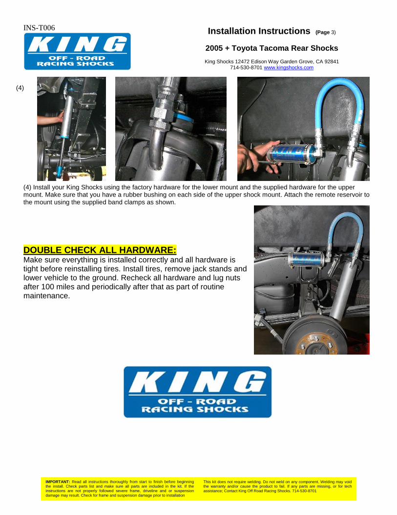
(1) With the vehicle on level ground and the front tires blocked, use a floor jack to raise the rear end and support the frame rails with jack stands for safety. Then remove the rear tires. NOTE: Never work under an unsupported vehicle.
(2) On the driver’s side of the truck (left), remove the bolts holding the brake line bracket to the frame as shown. Insert the reservoir bracket between the brake bracket and the frame as shown. Replace the bolts and tighten. On the opposite side
(right) mount the bracket with the provided hardware using the existing holes in the frame.
(2) (2)

INS-T006
IMPORTANT: Read all instructions thoroughly from start to finish before beginning the install. Check parts list and make sure all parts are included in the kit. If the instructions are not properly followed severe frame, driveline and or suspension damage may result. Check for frame and suspension damage prior to installation
This kit does not require welding. Do not weld on any component. Welding may void the warranty and/or cause the product to fail. If any parts are missing, or for tech
assistance; Contact King Off Road Racing Shocks. 714-530-8701
Installation Instructions (Page 2)
2005 + Toyota Tacoma Rear Shocks
King Shocks 12472 Edison Way Garden Grove, CA 92841 714-530-8701 www.kingshocks.com
(3) Remove the factory shocks by removing the hardware from the upper and lower mounts.
Note: Some Tacoma’s have a clearance issue with the gusset in the rear lower shock mount. If your Tacoma has this issue it may be necessary to grind or bend the tab to make room for the lower rod end on your King Shocks. See Photos below.
(2) (3) (3)
(4)
(4)
INS-T006
IMPORTANT: Read all instructions thoroughly from start to finish before beginning the install. Check parts list and make sure all parts are included in the kit. If the instructions are not properly followed severe frame, driveline and or suspension damage may result. Check for frame and suspension damage prior to installation
This kit does not require welding. Do not weld on any component. Welding may void the warranty and/or cause the product to fail. If any parts are missing, or for tech
assistance; Contact King Off Road Racing Shocks. 714-530-8701
Installation Instructions (Page 3)
2005 + Toyota Tacoma Rear Shocks
King Shocks 12472 Edison Way Garden Grove, CA 92841 714-530-8701 www.kingshocks.com
(4) Install your King Shocks using the factory hardware for the lower mount and the supplied hardware for the upper mount. Make sure that you have a rubber bushing on each side of the upper shock mount. Attach the remote reservoir to the mount using the supplied band clamps as shown.
DOUBLE CHECK ALL HARDWARE: Make sure everything is installed correctly and all hardware is tight before reinstalling tires. Install tires, remove jack stands and lower vehicle to the ground. Recheck all hardware and lug nuts after 100 miles and periodically after that as part of routine maintenance.
(4)
DATE: 5/9/2007REV.: 02SCALE: N.T.S.PAGE: 1 OF 4DRAWN: SW
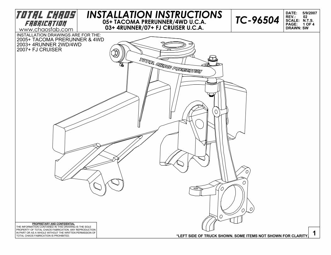
*LEFT SIDE OF TRUCK SHOWN. SOME ITEMS NOT SHOWN FOR CLARITY. 1 PROPRIETARY AND CONFIDENTIAL
THE INFORMATION CONTAINED IN THIS DRAWING IS THE SOLEPROPERTY OF TOTAL CHAOS FABRICATION. ANY REPRODUCTIONIN PART OR AS A WHOLE WITHOUT THE WRITTEN PERMISSION OFTOTAL CHAOS FABRICATION IS PROHIBITED.
INSTALLATION INSTRUCTIONSwww.chaosfab.com
TC-9650405+ TACOMA PRERUNNER/4WD U.C.A.03+ 4RUNNER/07+ FJ CRUISER U.C.A.
INSTALLATION DRAWINGS ARE FOR THE:2005+ TACOMA PRERUNNER & 4WD2003+ 4RUNNER 2WD/4WD2007+ FJ CRUISER

APPLY GENEROUSAMOUNTS OF
GREASE TO OUTSIDE OF SLEEVES AND I.D. OF URETHANE BUSHINGS
APPLY GENEROUSAMOUNTS OF
GREASE TO OUTSIDE OF SLEEVES AND I.D. OF URETHANE BUSHINGS
2
3
1
3
4
4
DATE: 5/9/2007REV.: 02SCALE: N.T.S.PAGE: 2 OF 4DRAWN: SW
*LEFT SIDE OF TRUCK SHOWN. SOME ITEMS NOT SHOWN FOR CLARITY. 2 PROPRIETARY AND CONFIDENTIAL
THE INFORMATION CONTAINED IN THIS DRAWING IS THE SOLEPROPERTY OF TOTAL CHAOS FABRICATION. ANY REPRODUCTIONIN PART OR AS A WHOLE WITHOUT THE WRITTEN PERMISSION OFTOTAL CHAOS FABRICATION IS PROHIBITED.
INSTALLATION INSTRUCTIONSwww.chaosfab.com
TC-9650405+ TACOMA PRERUNNER/4WD U.C.A.03+ 4RUNNER/07+ FJ CRUISER U.C.A.

6
7
10
11
12
5
Important Note:When removing the factory upper control arm bolt, you will need to
bend the inner fender well on both sides of the truck. Once installation
is complete, bend it back to its orignal position.
FACTORY BOLT
FACTORY NUT
SPINDLE
DATE: 5/9/2007REV.: 02SCALE: N.T.S.PAGE: 3 OF 4DRAWN: SW
*LEFT SIDE OF TRUCK SHOWN. SOME ITEMS NOT SHOWN FOR CLARITY. 3 PROPRIETARY AND CONFIDENTIAL
THE INFORMATION CONTAINED IN THIS DRAWING IS THE SOLEPROPERTY OF TOTAL CHAOS FABRICATION. ANY REPRODUCTIONIN PART OR AS A WHOLE WITHOUT THE WRITTEN PERMISSION OFTOTAL CHAOS FABRICATION IS PROHIBITED.
INSTALLATION INSTRUCTIONSwww.chaosfab.com
TC-9650405+ TACOMA PRERUNNER/4WD U.C.A.03+ 4RUNNER/07+ FJ CRUISER U.C.A.
Upper spacer has 9/16" hole
Lower spacer has 3/4" hole
IMPORTANT NOTE:During assembly, upper & lower spacers are specific.
Failure to follow these instructions will result in
damage of all components.
9
8
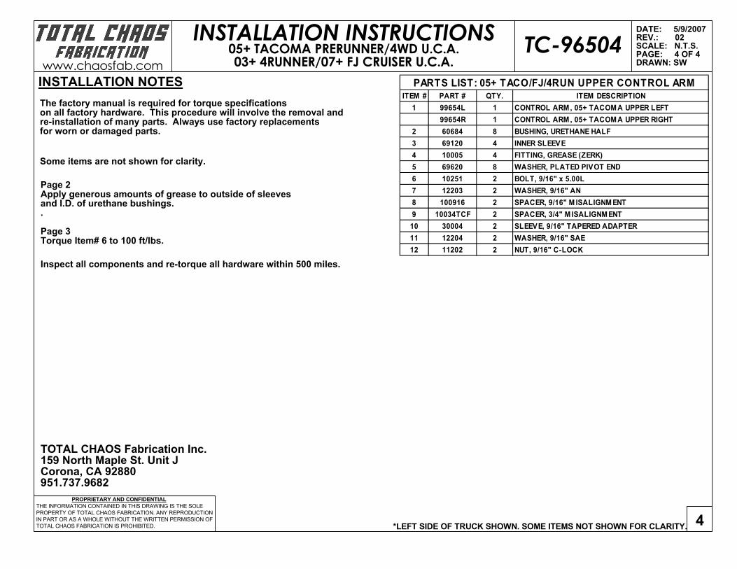
Inspect all components and re-torque all hardware within 500 miles.
Some items are not shown for clarity.
The factory manual is required for torque specifications on all factory hardware. This procedure will involve the removal andre-installation of many parts. Always use factory replacementsfor worn or damaged parts.
Page 2Apply generous amounts of grease to outside of sleeves and I.D. of urethane bushings. .
Page 3Torque Item# 6 to 100 ft/lbs.
TOTAL CHAOS Fabrication Inc.159 North Maple St. Unit JCorona, CA 92880951.737.9682
INSTALLATION NOTES
DATE: 5/9/2007REV.: 02SCALE: N.T.S.PAGE: 4 OF 4DRAWN: SW
*LEFT SIDE OF TRUCK SHOWN. SOME ITEMS NOT SHOWN FOR CLARITY. 4 PROPRIETARY AND CONFIDENTIAL
THE INFORMATION CONTAINED IN THIS DRAWING IS THE SOLEPROPERTY OF TOTAL CHAOS FABRICATION. ANY REPRODUCTIONIN PART OR AS A WHOLE WITHOUT THE WRITTEN PERMISSION OFTOTAL CHAOS FABRICATION IS PROHIBITED.
INSTALLATION INSTRUCTIONSwww.chaosfab.com
TC-9650405+ TACOMA PRERUNNER/4WD U.C.A.03+ 4RUNNER/07+ FJ CRUISER U.C.A.
ITEM # PART # QTY. ITEM DESCRIPTION1 99654L 1 CONTROL ARM, 05+ TACOMA UPPER LEFT
99654R 1 CONTROL ARM, 05+ TACOMA UPPER RIGHT2 60684 8 BUSHING, URETHANE HALF3 69120 4 INNER SLEEVE4 10005 4 FITTING, GREASE (ZERK)5 69620 8 WASHER, PLATED PIVOT END6 10251 2 BOLT, 9/16" x 5.00L7 12203 2 WASHER, 9/16" AN8 100916 2 SPACER, 9/16" M ISALIGNM ENT 9 10034TCF 2 SPACER, 3/4" M ISALIGNM ENT
10 30004 2 SLEEVE, 9/16" TAPERED ADAPTER11 12204 2 WASHER, 9/16" SAE12 11202 2 NUT, 9/16" C-LOCK
PARTS LIST: 05+ TACO/FJ/4RUN UPPER CONTROL ARM

www.toyteclifts.com
ADD-A-LEAF INSTALLATION INSTRUCTIONS [email protected]
Prior to installation, please read all install directions and paperwork provided.
ToyTec Lifts L.L.C. recommends that all components be installed by a certified automotive technician.
1. Park on a level concrete surface with the tires straight and steering wheel locked in the center position.
2. Block/chock the front wheels, both in front and behind the tire to prevent vehicle movement.
3. Jack the rear end of your vehicle up using a floor jack positioned on the axle pumpkin. Secure the vehicle on
suitable large jack stands from the frame on both sides. Leave the floor jack under the axle pumpkin with
some upwards pressure on it.
4. Remove both rear wheels/tires.
5. Disconnect the E-brake cable via the pins attached to the drum brake levers on both sides (‘95.5-’04 Tacoma
only).
6. Remove the shocks on both sides.
7. Be certain that the axle is well supported and remove the axle U-bolts, axle plates, bump stops, and all
hardware on both sides. Slowly lower the axle so there is enough room between the spring perch and spring
to install the add-a-leafs. Be careful not to overextend the rear soft brake line leading from the axle to the
frame!
8. Using 2 large C-clamps hold the spring assembly securely together on each side of the spring centering bolt.
Loosen and remove the bolt. A pair of vice grips may be needed to hold the center bolt head from spinning
while removing the nut.
9. Taking note as to the order the leaf pack is assembled, carefully loosen and remove the C-clamps. Note the
placement of any shims or spring dividers for re-assembly. If your factory leaf springs have a roll pin
through the leaf springs, it will need to be removed and discarded
10. Apply a small amount of grease to the friction pads of the add-a-leaf and place it in the correct place within
the leaf pack.
11. Note that the add-a-leaf must be placed in the correct order- Longest leaf being on top (main leaf) and
progressing to the shortest on the bottom (overload spring). The add-a-leaf should be below the main
leafs and above the short thick overload leaf. IF YOUR ADD-A-LEAF HAS A LONGER SIDE THAN THE OTHER,
THE LONGER END OF THE ADD-A-LEAF SHOULD BE FACING TOWARD THE REAR OF THE TRUCK. DO NOT
INSTALL THE ADD-A-LEAF BELOW THE OVERLOAD SPRING!
12. Use a screwdriver or small punch and line up the individual leafs and then slide the center pin up through
the leafs. Squeeze the thinner leafs within the pack together using C-clamps, continually aligning the center
holes. NOTE: If your lift kit is supplied with the solid steel axle shims, place the center bolt through the
shim center hole prior to installing the center pin in the leaf pack. The thinner end of the shim should face
toward the front of the vehicle.

www.toyteclifts.com
13. USE C-CLAMPS TO PULL THE SPRING PACK TOGETHER, NOT THE SPRING CENTER BOLT! Torque the center
bolt to manufacturer specs and cut most of the remaining threads off the centering bolt so the bump stop
fits correctly.
14. Re-install all bump stops, U-bolts, axle plates, washers, and nuts. Torque U-bolt nuts to manufacturer specs.
15. If your kit came with a Brake Proportioning Valve Bracket Kit now is a good time to install this.
16. Re-install shocks, E-brake cables, and rear wheels. Torque all bolts and lug nuts to manufacturer specs.
17. Lower the vehicle and test drive.
Recheck the torque of all bolts/nuts which have been taken apart during the installation of this lift after 15
miles, and periodically thereafter.

Diff-Drop Kit Installation Instructions:
2005+ Tacoma, 07+ FJ, 03+ 4Runner
Stock (fig. 1) Diff Drop kit Installed (Fig. 2)
1. Remove skid plate from front of the vehicle, save the OEM bolts.
2. Support the differential with a floor jack
3. Remove factory M14 bolts and nuts, supporting the front differential, see Fig. 1 above for
the stock configuration. Save the OEM washers for re installation.
4. Lower differential far enough to allow insertion of the 1" drop spacers.
5. Install the 1" spacers between the two front differential supports and front cross-member.
(see Figure 2 above) . Fasten to cross-member using new 1/2" x 6" long Grade 8 bolts
and nuts (making sure to reuse the factory washers).Tighten to the factory specifications
(If you don't have the factory specs, 80-90 ft.lbs. should be adequate for this size/grade
bolt) Figure 2 shows the diff drop kit installed.
6. Install the front skid plate using the OEM bolts on the front and the supplied longer bolts
with washers and skid spacers on the rear mounting point.
7. Install rear skid plate using the small supplied spacers and longer bolts with washers
between the frame and skid plate on the front and the OE bolts on the rear of the skid
plate to prevent skid plate to differential mounting bracket interference.
8. Skid plate trimming may be required on some models.
9. Torque all skid plate bolts to factory specifications. (25 ft lbs should be adequate.)

3 Degree Rear Axle Shims installation Instructions: Place the center bolt through the shim center hole prior to installing the center pin in the leaf pack. The thinner end of the shim should face toward the front of the vehicle.