innovative movement monitoring system for elderly · pdf fileinnovative movement monitoring...
TRANSCRIPT

Innovative Movement Monitoring System for Elderly using Passive
Infrared and Linear Phased Antenna Arrays
S. SFICHI, A. GRAUR, V. POPA, I. FINIS, A. LAVRIC
Department of Computers, Electronics and Automation, “Stefan cel Mare” University of Suceava,
Str. Universitatii nr.13, RO-720229 Suceava, Romania
Abstract: - This paper presents the development of a complex innovative system for detecting and monitoring
the movement of elderly people inside a living area. In order to achieve a desired low power consumption the
purposed system comprise of Passive Infrared (PIR) sensors for coarse movement detection and
Radiofrequency ZigBee network nodes equipped with phased antenna arrays for precise location estimation.
Each person wears a compact ZigBee personal identification node. The PIR sensors detect the movement of
persons inside the living area and activate the corresponding scanning nodes operating on 2.4 GHz band. The
scanning nodes perform a sweep across the living area and use scanning angle and RSSi information in order to
determine the location estimation of each ZigBee node worn by monitored persons. By placing the antenna
array node at one corner of room to be monitored the sweep must be of 90 degree. Various printed arrays
designs having patch and bowtie antenna as array elements were analysed with the help of Ansoft High
Frequency Structure Simulator suite in order to select a best match configuration for our purpose. In the end an
antenna array setup consisting of 9 bowtie shielded elements, placed at a distance of half wavelength was
chosen for implementation of the system.
Key-Words: - Linear antenna arrays, Microstrip antenna arrays, Motion detection, Phased arrays.
1 Introduction As a result of increased living standards and with
the help of new medical achievements that reduce
premature mortality, the aging of the population is
an important factor in today society. People
nowadays have more freedom to choose whether
and when they want to raise children and many
young people prefer to devote themselves to gain
professional recognition and leave in the second
plan the raising of children. This leads to a
pronounced decrease in the birth rate and many
fears that life will be much more difficult in an older
society in which we live and there will be inevitable
tensions or even open conflicts between generations.
The aging process brings a number of changes in
the body that influence its physical functioning. The
levels of these changes are accentuated by the
presence of certain chronic diseases or genetic
predisposition [1]. Various modifications may be
identified at the sensory functions, at the level of
organs and anatomical systems, psychomotor
functioning, as well as the personality. These
changes may be a result of the normal aging process
called senescence or they are the consequence of the
pathological process which accelerates and
exaggerates the normal aging process, defined by
the concept of senility.
Age may create a situation of temporary or
permanent dependency or loss of personal autonomy
depending on the evolutionary potential of each
disease diagnosed.
Thus there are depended people with health
problems or any other kind that have to be
supervised inside a living area such as a healthcare
facility or even inside their house. Many don’t need
to be under specific supervision. They don’t need
another person to be around all the time and hiring
someone to act as a personal assistant or as a
superintendent in this case is very expensive and
unreasonably.
An automated and thus less costly system that
will keep track of the movement of these persons
inside a living area is a more feasible solution [2].
The system will also monitor vital signs status and it
will send an alarm to an Emergency Dispatch
Service when necessary. Such a system must be
integrated in healthcare facility or in the house of
depended people; it must have low power
consumption and its operation and functioning must
be completely transparent to an elderly person.
This article is focused on the development of an
innovative movement monitoring system for elderly
peoples, based on passive infrared and linear phased
antenna arrays operating on 2.4 GHZ ISM band.
The general system architecture and the study of
various antenna arrays configurations consisting of
printed antenna elements are presented. In order to
achieve precise location estimation the antenna
Advances in Automatic Control, Modelling & Simulation
ISBN: 978-1-61804-189-0 219

array must have a sweep of 90 degree, a narrow
main beam, low intensity and preferably few side
lobes [3]. Due to cost and size restrictions, the
number of antenna elements is also an important
factor in the design of the array. Simulations of
designed phased antenna arrays were performed on
Ansoft – High Frequency Structure Simulator.
2 System architecture The system presented in Fig. 1 and described in this
article is designed to accomplish the monitoring
process of elderly or depended persons at healthcare
facilities or at their own house. Thus, it is conceived
to be integrated in living areas without disturbing
the residents when used and to be highly
autonomous. The system consists of roughly four
major components: low power coarse movement
detection, accurate location estimation, vital signs
monitoring and a server which keeps track of
people’s activities, issues an alert when necessary
and act as a gateway to Emergency Dispatch
Services. The low power movement detection subsystem
comprises of Passive Infrared (PIR) sensors places
in every room. The PIR intrusion detection sensors
are used on massive scale on house alarm systems
and in industry, thus making them a mature, low
power and very inexpensive technology. Passive
infrared sensors are more energy efficient because
they detect electromagnetic radiated energy from
external sources, particularly that emitted by people,
while active infrared sensors generate a multiple
beam pattern of modulated infrared energy and react
to a change in the modulation of the frequency. This
emission of IR radiation makes the active infrared
system power hungry. The PIR sensors are
connected to the server via low power ZigBee
wireless network nodes (Yc). When a person moves
inside the area monitored by the PIR sensor, the
movement is detected and the sensor send a message
to server via ZigBee network.
The accurate location estimation subsystem is
built around a phased antenna array (AA) in order to
avoid limitations of path loss and indoor reflections,
operating on 2.4GHz [4]. The array makes a sweep
of the room to precisely locate the Vital Sign
Monitor (VSM) which acts as a beacon and it is
worn by the monitoring person. To preserve power
and to limit the use of electromagnetic spectrum, the
array scanning process is activated by the server
after the PIR sensor located in the same room
detects movement. The sweep is also initiated at
regular intervals to locate the persons which do not
move after periods of time.
Fig. 1 Movement Monitoring System implementation
inside a living area. PIR Sensor, Phased antenna array
and the ZigBee vital sign monitor are shown.
The phased antenna array subsystem uses beam
forming to create and steer a main beam from -45
degree to 45 degree measured to the array normal,
thus fully covering the 90 degree of sweep angle
inside a living area. The antenna array controller
initiate the scanning process by forming and
orienting the main beam to an angle of -45 degree,
and then ask the corresponding Vital Sign Monitor
to report the value of Received Signal Strength
indicator (RSSi). Next, the controller steers the main
beam to the next incremented scanning angle and
the process is repeated. When a full sweep is
completed, the antenna array controller computes
the location estimation based on received RSSi and
the corresponding steering angles. This information
is then transmitted to the server, and the antenna
array enters a low power state.
The server component of the system comprise of
a server connected to the entire ZigBee network. It
receives information from the PIR sensors when
they detect movement and activates the
corresponding antenna array in order to determine
the location estimation of persons inside the room
and records each person’s vital signs. The server
also keeps track of previous location for each person
and creates a map of movement in order to predict
the behaviour of peoples. In case a person does not
move for a longer period of time, or if the received
vital signs fall below a previously establish
threshold, an alarm is composed and transmitted to
an Emergency Dispatch Service, either as a voice
message, or as a SMS or data message.
3 Antenna arrays radiating elements As part of the development of the antenna array
creating the array radiating elements is an important
step. Since the antenna array must have relatively
low size in order to be installed indoors, we choose
to implement the radiating elements on printed
circuits board [5]. In order to maintain the array to
Advances in Automatic Control, Modelling & Simulation
ISBN: 978-1-61804-189-0 220
low cost margins we choose to use a common glass-
reinforced epoxy FR4 printed circuit board. The
technical documentation specifies for the chosen
material a dielectric thickness of 1.5mm, a relative
permittivity of 4.4, and a loss tangent of 0.015.
These information where used to design two types
of printed antenna, bowtie and rectangular patch
antenna with a resonant frequency of 2.4GHz.
Numerical simulations where conducted with the
help of Ansoft High Frequency Structure Simulator
suite. Ansoft HFSS is a well proven tool for 3D full
wave electromagnetic field simulation, offering
multiple solver technologies based on either the
finite element method, or the integral equation
method.
The shape and dimensions of the printed bowtie
antenna are shown in Fig. 2. The arm length is
12.9mm, outer radius is 9.34mm, outer width is16.9
mm, the port gap and the inner width is 0.71mm.
Fig. 2 Bowtie antenna radiating element shape and
dimensions
a) b)
c) d)
Fig. 3. Bowtie antenna reflection coefficients a),
Directivity for phi = 0° b), Directivity for phi = 90° c)
and 3D radiation pattern d)
From Fig. 3.a) the proposed bowtie printed
antenna has a large bandwidth and resonates at
2.4GHz. Normalized antenna directivity is plotted
for H and E plane on Fig. 3.b) and c). A 3D plot of
radiation pattern is shown in Fig. 3.c).
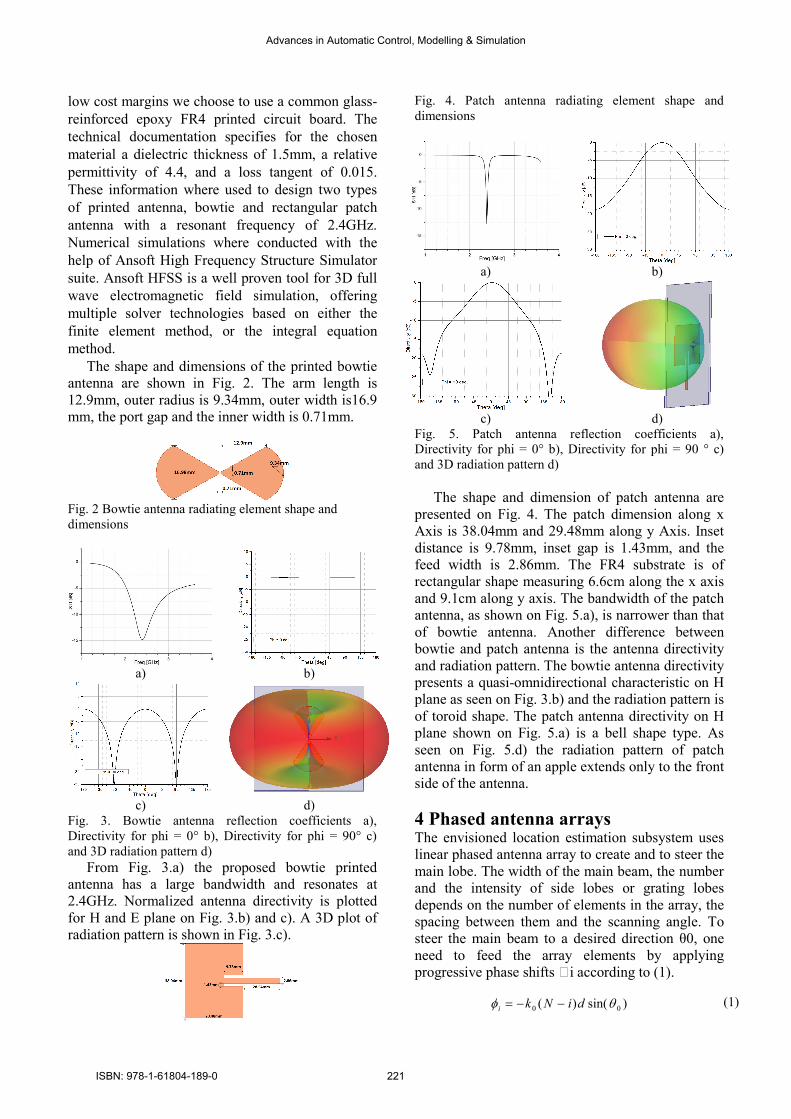
Fig. 4. Patch antenna radiating element shape and
dimensions
a) b)
c) d)
Fig. 5. Patch antenna reflection coefficients a),
Directivity for phi = 0° b), Directivity for phi = 90 ° c)
and 3D radiation pattern d)
The shape and dimension of patch antenna are
presented on Fig. 4. The patch dimension along x
Axis is 38.04mm and 29.48mm along y Axis. Inset
distance is 9.78mm, inset gap is 1.43mm, and the
feed width is 2.86mm. The FR4 substrate is of
rectangular shape measuring 6.6cm along the x axis
and 9.1cm along y axis. The bandwidth of the patch
antenna, as shown on Fig. 5.a), is narrower than that
of bowtie antenna. Another difference between
bowtie and patch antenna is the antenna directivity
and radiation pattern. The bowtie antenna directivity
presents a quasi-omnidirectional characteristic on H
plane as seen on Fig. 3.b) and the radiation pattern is
of toroid shape. The patch antenna directivity on H
plane shown on Fig. 5.a) is a bell shape type. As
seen on Fig. 5.d) the radiation pattern of patch
antenna in form of an apple extends only to the front
side of the antenna.
4 Phased antenna arrays The envisioned location estimation subsystem uses
linear phased antenna array to create and to steer the
main lobe. The width of the main beam, the number
and the intensity of side lobes or grating lobes
depends on the number of elements in the array, the
spacing between them and the scanning angle. To
steer the main beam to a desired direction θ0, one
need to feed the array elements by applying
progressive phase shifts ϕi according to (1).
)sin()( 00 θφ diNki −−= (1)
Advances in Automatic Control, Modelling & Simulation
ISBN: 978-1-61804-189-0 221
where k0 is the free-space wavenumber (2π/λ0)
and d represents the distance between antenna array
elements. N is the total number of array elements.
Having designed two types of printed antenna
array, the next step was to develop the antenna
array. We simulated various configurations of linear
antenna array with elements number ranging from 3
to 11, and spacing between antenna elements
between 0.25 and 0.75 wavelengths (λ). To
accomplish the requirements of our application the
antenna array should have a narrow main beam,
preferably no grating lobes in visible space, a low
number and low power of side lobes and the ability
to steer the main lobe from -45 degree to 45 degree
to the array normal.
a)
b) c)
d)
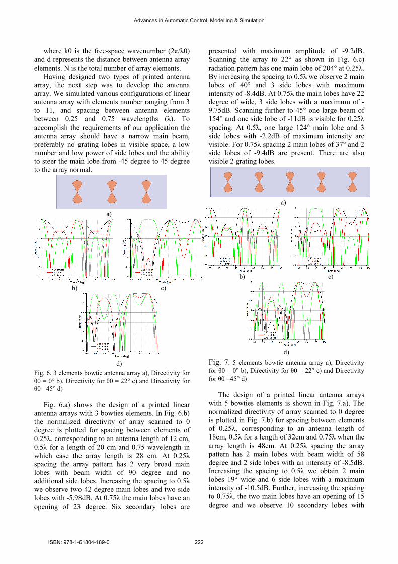
Fig. 6. 3 elements bowtie antenna array a), Directivity for
θ0 = 0° b), Directivity for θ0 = 22° c) and Directivity for
θ0 =45° d)
Fig. 6.a) shows the design of a printed linear
antenna arrays with 3 bowties elements. In Fig. 6.b)
the normalized directivity of array scanned to 0
degree is plotted for spacing between elements of
0.25λ, corresponding to an antenna length of 12 cm,
0.5λ for a length of 20 cm and 0.75 wavelength in
which case the array length is 28 cm. At 0.25λ
spacing the array pattern has 2 very broad main
lobes with beam width of 90 degree and no
additional side lobes. Increasing the spacing to 0.5λ
we observe two 42 degree main lobes and two side
lobes with -5.98dB. At 0.75λ the main lobes have an
opening of 23 degree. Six secondary lobes are
presented with maximum amplitude of -9.2dB.
Scanning the array to 22° as shown in Fig. 6.c)
radiation pattern has one main lobe of 204° at 0.25λ.
By increasing the spacing to 0.5λ we observe 2 main
lobes of 40° and 3 side lobes with maximum
intensity of -8.4dB. At 0.75λ the main lobes have 22
degree of wide, 3 side lobes with a maximum of -
9.75dB. Scanning further to 45° one large beam of
154° and one side lobe of -11dB is visible for 0.25λ
spacing. At 0.5λ, one large 124° main lobe and 3
side lobes with -2.2dB of maximum intensity are
visible. For 0.75λ spacing 2 main lobes of 37° and 2
side lobes of -9.4dB are present. There are also
visible 2 grating lobes.
a)
b) c)
d)
Fig. 7. 5 elements bowtie antenna array a), Directivity
for θ0 = 0° b), Directivity for θ0 = 22° c) and Directivity
for θ0 =45° d)
The design of a printed linear antenna arrays
with 5 bowties elements is shown in Fig. 7.a). The
normalized directivity of array scanned to 0 degree
is plotted in Fig. 7.b) for spacing between elements
of 0.25λ, corresponding to an antenna length of
18cm, 0.5λ for a length of 32cm and 0.75λ when the
array length is 48cm. At 0.25λ spacing the array
pattern has 2 main lobes with beam width of 58
degree and 2 side lobes with an intensity of -8.5dB.
Increasing the spacing to 0.5λ we obtain 2 main
lobes 19° wide and 6 side lobes with a maximum
intensity of -10.5dB. Further, increasing the spacing
to 0.75λ, the two main lobes have an opening of 15
degree and we observe 10 secondary lobes with
Advances in Automatic Control, Modelling & Simulation
ISBN: 978-1-61804-189-0 222

maximum amplitude of -10.26dB. When we
increase the scanning angle of the array to 22° we
observe for 0.25λ spacing 2 main lobes with 46
degree of beam wide. At 0.5λ of spacing 2 main
lobes of 20° are visible and 6 side lobes with
maximum intensity of -7.2 dB. At 0.75λ the 2 main
lobes have a wide of 10°. Nine side lobes with
maximum intensity of -13.5 dB and 2 grating lobes
are present. Scanning further to 45° as in Fig. 7.d) a
large beam of 122° and 3 side lobes with -13.9dB
maxim intensity are visible for 0.25λ spacing. At
0.5λ two 30° main lobe and 7 side lobes with -7.9dB
of maximum intensity are visible. For 0.75λ spacing
2 main lobes of 21° and 8 side lobes of -11 dB are
present. There are also visible 2 grating lobes.
a)
b) c)
d)
Fig. 8. 9 elements bowtie antenna array a), Directivity for
θ0 = 0° b), Directivity for θ0 = 22° c) and Directivity for
θ0 =45° d)
Fig. 8.a) presents the design of a printed linear
antenna arrays with 9 bowties elements. In Fig. 8.b)
the normalized directivity of array scanned to 0
degree is plotted for spacing between elements of
0.25λ, corresponding to an antenna length of 30 cm,
0.5λ for a length of 56cm and 0.75 wavelength in
which case the array length is 88cm. At 0.25λ
spacing between the elements the array pattern has 2
main lobes with main beam of 20° width and 6
additional side lobes with a maximum intensity of -
12dB. By increasing the spacing to 0.5 λ we observe
two 11 degree main lobes and 14 side lobes with a
maximum peak of -13.35 dB. At 0.75 λ the two
main lobes have an opening of 7 degree. 22
secondary lobes are visible, having maximum
amplitude of -11.9 dB. Scanning the array to 22°
scanning angle, the radiation pattern has 2 main
lobes of 30° at 0.25 λ and 6 side lobes with a
maximum intensity of -7°. Increasing the spacing to
0.5 λ we observe 2 main lobes of 12° and 15 side
lobes with maximum intensity of -12.3 dB. At a
spacing of 0.75 λ the 2 main lobes have a width of
7°. There are also present 20 side lobes with a max
of -14.29 dB. Further changing the array scanning
angle to 45° as in Fig. 8.d) it can be observed two
large beams of 106° and 6 side lobes of -15dB
visible for 0.25λ spacing. At 0.5λ, 2 main lobes of
19° and 14 side lobes with -8.5 dB of maximum
intensity are visible. For 0.75λ spacing 2 main lobes
of 9° and 19 side lobes of -9.4 dB are present. There
are also visible 2 grating lobes.
a)
b) c)
d)
Fig. 9. 11 elements bowtie antenna array a),
Directivity for θ0 = 0°. b), Directivity for θ0 = 22° c) and
Directivity for θ0 =45° d) In Fig. 9.a) is shown the design of 11 elements
bowties printed antenna array. In Fig. 9.b) the
normalized directivity of the array scanned to 0
degree is plotted for spacing between elements of
0.25λ, corresponding to an antenna length of 36cm,
0.5λ for a length of 68cm and 0.75 wavelength in
which case the array length is 108cm.
At spacing between array elements of 0.25λ the
array pattern has 2 main lobes with beam width of
17 degree and 8 additional side lobes with a
maximum intensity of -13.2dB. Increasing the
distance between elements to 0.5λ the radiation
pattern presents two 10 degree main lobes and 18
side lobes with a maximum intensity of -12.3dB. At
0.75λ the main lobes have an opening of 6 degree.
30 secondary lobes are presented with maximum
Advances in Automatic Control, Modelling & Simulation
ISBN: 978-1-61804-189-0 223

amplitude of -13.2dB. Changing the array scanning
angle to 22°, radiation pattern has two main lobes of
22° at 0.25λ. The eight side lobes have a maximum
intensity of -8.6dB. Increasing the spacing to 0.5λ
we observe that the 2 main lobes have a wide of 11°
and the 18 side lobes have a maximum intensity of -
12.3dB. At 0.75λ spacing between bowtie elements
the 2 main beams have a wide of 6°. The 27 side
lobes have a maximum value of -14.7dB. Scanning
further to 45° the two large main beams of 26° and 7
side lobe of maximum -15dB is visible for 0.25λ
spacing. At 0.5λ, two main lobes of 15° wide and 19
side lobes with a maximum intensity of -8.6dB are
visible. For spacing of 0.75λ two main lobes of 9°
and 26 side lobes of -11.6dB maximum intensity
plus 2 grating lobes are present.
a)
b) c)
d) e)
f) g)
Fig. 10. 9 elements patch antenna array a), Directivity for
θ0 = 0° with spacing between 0.35λ and 0.5λ b),
Directivity for θ0 = 0° with spacing between 0.5λ and
0.75λ c) Directivity for θ0 = 22° with spacing between
0.35λ and 0.5λ d), Directivity for θ0 = 22° with spacing
between 0.5λ and 0.75λ e) Directivity for θ0 = 45° with
spacing between 0.35λ and 0.5λ f), Directivity for θ0 =
45° with spacing between 0.5λ and 0.75λ g)
Analysing the results of bowtie array simulations
we concluded that the best compromise between
array size, array elements, the beam width of the
main lobe, the number and intensity of side lobes, is
to use an array with 9 elements spaced at 0.5λ in the
case of bowtie antenna elements. One important
characteristic of bowtie antenna array is the
presence of two main beams, one on each side of the
array. This may seem to be an inconvenience since
it is introducing an uncertainty factor if the signal
from the back of antenna penetrates the wall of an
adjacent room. However a setup consisting of a
bowtie antenna array can be used for simultaneous
scanning in two neighbouring room and
differentiation of targets can be done via PIR sensor
information, Wrist Vital Signs Monitoring id or by
the patterns of movement computed and stored by
the server.
In cases where the wall attenuation is too great to
use such a setup with good results it is necessary to
have an antenna array with only one main beam.
Therefore based on results already obtained we
designed a rectangular patch antenna array with 9
elements. We conducted various simulations with
spacing of antenna elements varying from 0.35λ to
0.75λ at several scanning angles and the directivity
of array in H plane was plotted in Fig. 10. Again, we
considerate that the best configuration for our use is
the antenna array with half wavelength spacing
between array elements.
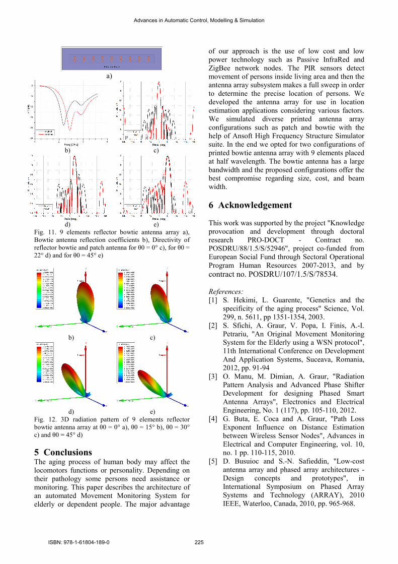
Another antenna design developed during this
research was made by placing a reflector plate at the
back of a bowtie antenna array as shown in Fig.
11.a) in order to obtain only one main beam directed
to the front of the antenna. The reflector plate
connected to the ground was placed at 4 cm behind
the array. This modification altered the reflection
coefficient of the antenna elements, changing the
resonant frequency. We changed the dimensions of
the printed bowtie in order to make antenna resonant
again at 2.4 GHz, by increasing the outer width to
17mm and the outer radius to 11.3mm. The
reflection coefficient S11 values for original and
modified bowtie antenna element are plotted in Fig.
11.b). The directivity of 9 elements reflector bowtie
antenna in H plane is plotted on Fig. 11. c) to Fig.
11.e) along the directivity of 9 elements patch
antenna array for scanning angles of 0°, 22° and
45°.
Fig. 12 plots the 3D radiation pattern of 9
elements reflector bowtie with interspacing of 0.5 λ
between array elements at scanning angles of 0° a),
15° b), 30° c) and 45° d).
Advances in Automatic Control, Modelling & Simulation
ISBN: 978-1-61804-189-0 224
a)
b) c)
d) e)
Fig. 11. 9 elements reflector bowtie antenna array a),
Bowtie antenna reflection coefficients b), Directivity of
reflector bowtie and patch antenna for θ0 = 0° c), for θ0 =
22° d) and for θ0 = 45° e)
b) c)
d) e)
Fig. 12. 3D radiation pattern of 9 elements reflector
bowtie antenna array at θ0 = 0° a), θ0 = 15° b), θ0 = 30°
c) and θ0 = 45° d)
5 Conclusions The aging process of human body may affect the
locomotors functions or personality. Depending on
their pathology some persons need assistance or
monitoring. This paper describes the architecture of
an automated Movement Monitoring System for
elderly or dependent people. The major advantage
of our approach is the use of low cost and low
power technology such as Passive InfraRed and
ZigBee network nodes. The PIR sensors detect
movement of persons inside living area and then the
antenna array subsystem makes a full sweep in order
to determine the precise location of persons. We
developed the antenna array for use in location
estimation applications considering various factors.
We simulated diverse printed antenna array
configurations such as patch and bowtie with the
help of Ansoft High Frequency Structure Simulator
suite. In the end we opted for two configurations of
printed bowtie antenna array with 9 elements placed
at half wavelength. The bowtie antenna has a large
bandwidth and the proposed configurations offer the
best compromise regarding size, cost, and beam
width.
6 Acknowledgement
This work was supported by the project "Knowledge
provocation and development through doctoral
research PRO-DOCT - Contract no.
POSDRU/88/1.5/S/52946", project co-funded from
European Social Fund through Sectoral Operational
Program Human Resources 2007-2013, and by
contract no. POSDRU/107/1.5/S/78534.
References:
[1] S. Hekimi, L. Guarente, "Genetics and the
specificity of the aging process" Science, Vol.
299, n. 5611, pp 1351-1354, 2003.
[2] S. Sfichi, A. Graur, V. Popa, I. Finis, A.-I.
Petrariu, "An Original Movement Monitoring
System for the Elderly using a WSN protocol",
11th International Conference on Development
And Application Systems, Suceava, Romania,
2012, pp. 91-94
[3] O. Manu, M. Dimian, A. Graur, "Radiation
Pattern Analysis and Advanced Phase Shifter
Development for designing Phased Smart
Antenna Arrays", Electronics and Electrical
Engineering, No. 1 (117), pp. 105-110, 2012.
[4] G. Buta, E. Coca and A. Graur, "Path Loss
Exponent Influence on Distance Estimation
between Wireless Sensor Nodes", Advances in
Electrical and Computer Engineering, vol. 10,
no. 1 pp. 110-115, 2010.
[5] D. Busuioc and S.-N. Safieddin, "Low-cost
antenna array and phased array architectures -
Design concepts and prototypes", in
International Symposium on Phased Array
Systems and Technology (ARRAY), 2010
IEEE, Waterloo, Canada, 2010, pp. 965-968.
Advances in Automatic Control, Modelling & Simulation
ISBN: 978-1-61804-189-0 225