innovative design and development of … design and development of ... other gearing in windmills,...
TRANSCRIPT
International Journal of Scientific & Engineering Research, Volume 7, Issue 3, March-2016 80 ISSN 2229-5518
IJSER © 2016 http://www.ijser.org
Innovative Design and Development of Transmission System for an Off-road Vehicle
Boby George, Abin Jose, Adarsh John George, AjoyAugstine, Alvin Reji Thomas
Abstract—A transmission is a machine that consists of a power source and a power transmission system, which provides controlled application of the power. Often the term transmission refers simply to the gearbox that uses gears and gear trains to provide speed and torque conversions from a rotating power source to another device. Often, a transmission has multiple gear ratios with the ability to switch between them as speed varies. This switching may be done manually or automatically. Here we are converting a four speed manual gearbox into single speed constant mesh gearbox. This transmission is designed for an All-Terrain Vehicle, which is to be used in Baja student competition. An All-Terrain Vehicle is a single seat, open cockpit, open wheel off road vehicle with an engine positioned behind the driver. The All-Terrain Vehicle, which we have designed for the Baja student competition is as per the regulations of the championship. The manual gearbox being used here is a Mahindra Champion Alfa gearbox. The manual gearbox is coupled to a continuously variable transmission (CVT). A CVT is an automatic transmission that can change seamlessly through an infinite number of effective gear ratios between maximum and minimum values. This combination of manual gearbox and CVT is designed in such a way that it provides the required gear ratio and satisfies our requirement for an All-Terrain Vehicle.
Index Terms—All terrain vehicle, bracking, differential, gear, roll cage, shaft, steering system, suspension, transmission, vechicle, wheel.
————————————————————
1 INTRODUCTIONmachine consists of a power source and a power trans-mission system, which provides controlled application of the power. The transmission is an assembly of parts in-
cluding the speed changing gears and the propeller shaft by which the power is transmitted from an engine to a live axle. Often transmission refers simply to the gearbox that uses gears and gear trains to provide speed and torque conversions from a rotating power source to another device.The most common use is in motor vehicles, where the transmission adapts the output of the internal combustion engine to the drive wheels. Such engines need to operate at a relatively high rotational speed, which is inappropriate for starting, stopping, and slower travel. The transmission reduces the higher engine speed to the slower wheel speed, increasing torque in the pro-cess. Transmissions are also used on pedal bicycles, fixed ma-chines, and anywhere rotational speed and torque must be adapted. Transmissions helps to increase the efficiency of the vehicles. It helps the vehicles to drive through different ter-rains. Transmissions enables the transfer of required power for the vehicle for various road conditions or terrains. Transmis-sions are of different types like manual, automatic, semi-automatic, etc.
————————————————
• Boby George, AssiatantProfessor,Mechanical Engineering Department,
VimalJyothi Engineering College Chemperi,Kannur,India,[email protected]
• Co-Author Mechanical Engineering, VimalJyothi Engineering College, Chem-peri, Kannur.
2 SUSPENSION SYSTEM The term transmission refers to the whole drive train, in-
cluding clutch, gearbox, prop shaft (for real wheel drive), dif-ferential and final drive shafts. The term refers more specifi-cally to the gearbox alone, and the usage details are different. Early transmissions included the right-angle drives and other gearing in windmills, horse powered devices, and steam engines, in support of pumping, milling and hoisting. Most modern gearboxes are used to increase torque while reducing the speed of a prime mover output shaft. This means that the output shaft of a gearbox rotates at a slower rate than the in-put shaft, and this reduction in speed produces a mechanical advantage, increasing torque. A gearbox can be set up to do the opposite and provide an increase in shaft speed with a reduction of torque. Some of the simplest gearboxes merely change the physical rotational direction of power transmis-sion. Many typical automobile transmissions include the ability to select one of several different gear ratios. In this case, most of the gear ratios (often simply called gears) are used to slow down the output speed of the engine and increase torque. However, the highest gears may be overdrive types that in-crease output speed. The most common use is in motor vehi-cles, where the transmission adapts the output of the internal combustion engine to the drive wheels. Such engines need to operate at a relatively high rotational speed, which is inap-propriate for starting, stopping, and slower travel. The trans-mission reduces the higher engine speed to the slower wheel speed, increasing torque in the process. Transmissions are also used on pedal bicycles, fixed machines, and anywhere rota-tional speed and torque must be adapted. Often, a transmis-sion has multiple gear ratios (or simply gears), with the ability to switch between them as speed varies. This switching may be done manually or automatically. Directional (forward and reverse) control may also be provided. Single-ratio transmis-sions also exist, which simply change the speed and torque (and sometimes direction) of motor output. In motor vehicles, the transmission generally is connected
A
IJSER
International Journal of Scientific & Engineering Research, Volume 7, Issue 3, March-2016 81 ISSN 2229-5518
IJSER © 2016 http://www.ijser.org
to the engine crankshaft via a flywheel and/or clutch and/or fluid coupling, partly because internal combustion engines cannot run below a particular speed. The output of the trans-mission is transmitted via driveshaft to one or more differen-tials, which in turn, drive the wheels. While a differential may also provide gear reduction, its primary purpose is to permit the wheels at either end of an axle to rotate at different speeds (essential to avoid wheel slippage on turns) as it changes the direction of rotation. 2.1 Specification of Gears: Gears are generally specified by their
Type; eg. Spur, bevel, spiral, etc. Material Size or dimensions Geometry Special features, if any
i. Gear materials: The materials of most of the gears used for transmitting rea-sonable torque and speed mainly need to be mechanically strong in shear and bending, sufficiently tough and resistant to wear, fatigue and chemical degradation. However, the material for any gear is selected based on,
Working condition, i.e., power, speed and torque to be transmitted. Working environment, i.e., tempera-ture, vibration, chemical, etc. Ease of manufacture. Overall cost of material and manu-facture.
The materials generally used for making gears are: Ferrous metals – for high loads
Grey cast iron – preferred for reasonable strength and wear resistance, ease of casting and ma-chining and low cost. Forged or rolled high carbon steels and al-loy steels (Ni-Cr, Mo, etc.) – which are either fully hardened or surface hardened for use under high stresses and speed.
Nonferrous metals – for light load
Aluminium, bronze and brass are used for making gears having fine teeth and working at very light load – e.g., in equipments, toys, etc. or against hard steel mating gears. Aluminium alloys like aluminium bronze, Zinc – Al. alloy, etc.
Non-metals – widely used for light load, non-precision and noiseless operation. Polymers (plastics): both thermoplastic and thermosetting type and various composites (metals, graphite, wood dust or ceramic powders dispersed in thermo-setting plastics). ii. Size or major dimensions:
The dimensional features that are used to express or specify the gears are; For spur gears and worm wheels
• Number of teeth, z • Module, m • Helix angle, if any • Width
iii. Gear Geometry: Some geometrical features also need to be mentioned while specifying gears, such as,
Pressure angle Addendum and Dedendum
iv. Special features: If there is any special feature, that also has to be included with gear specification, such as
• Tooth beveling for safe handling • Tooth crowning for uniform wear and long service life Tooth rou nding for easy engagem ent.
3 GEAR BOX DESIGN 3.1 Engine Specifications ENGINE : BRIGGS & STRATTON 20S232-0036 DISPLACEMENT : 305 CC MAX. POWER : 10 HP @ 3600 RPM ENGINE TYPE : OHV MAX. RPM : 3800 MAX TORQUE : 19 Nm @ 2800 RPM LUBRICATION SYSTEM : SPLASH BORE DIAMETER : 3.12 in STROKE LENGTH : 2.44 in CHOKE CONTROL : MANUAL IGNITION SYSTEM : ELECTRONIC CARBURETOR : FLOAT GOVERNOR SYSTEM : MECHANICAL 3.2 Calculations Major factors considered Tractive Force = 2073.97 N Rolling Resistance = 706.27N Gradient Resistance = 1425.16N (at 60% gradability) Aerodynamic Resistance = 80.51N Static Resistance = 1569.6N For the designing of gear reduction; • Total Resistance = Rolling Resistance + Aerodynamic
Drag + Static Resistance = 706.27 + 80.51 + 1569.6 = 2356.38 N •Total Torque acted on wheel = Total Resistance × wheel
radius = 2356.38 × 0.3175 = 748.15 ≈ 750 Nm
IJSER

International Journal of Scientific & Engineering Research, Volume 7, Issue 3, March-2016 82 ISSN 2229-5518
IJSER © 2016 http://www.ijser.org
3.2.1 Gear ratio calculation Torque at wheels = Engine Torque × CVT Ratio × required
Ratio× Differential Ratio 750 = 19×3×required ratio×3.875 Required Ratio = 3.39 ≈ 3.4 CALCULATED VELOCITY AND ACCELERATION TABLE 1
Velocity And Acceleration
GEAR RA-TIO
MAX SPEED
(kmph)
TRAC-TIVE
FORCE (N)
ACCELERA-TION
(m/s2)
AT LOWER
GEAR RATIO
39.52
10.88
1502.57 7.39
AT HIGHER
GEAR RATIO
5.66 75.4 215.16 1.05
Fig.1 velocity v/s tractive force curve 3.2.2 Grade ability Highest grade a vehicle can ascend maintaining a par-
ticular speed Max. Grad ability = 60% Factors affecting grade ability • Rolling Resistance
• Gradient Resistance • Aerodynamic Resistance • Tractive Force
Fig. 2 grad ability curve
4 DESIGN CALCULATIONS 4.1 Main constraints: Center to center distance of stock gear box Maximum space available for placing the gear To meet the required reductions or desired perfor-
mance of reductions Keeping the same module of existing gear box (m=
2.5) 4.2 Determination of possible reduction: 4.2.1 FIRST REDUCTION: Center to center distance = 75mm From the properties of gear mechanics, we know that DP/2 + DG/2 = Center to center distance …… (1) DP = Diameter of the pitch circle DG = Diameter of the gear Also we know that, DG/DP = gear ratio / reduction For the calculation we assume that first reduction = 1.1 Therefore, DG/DP = 1.1 DG= 1.1 DP Applying in eq. (1) 1.1 DP/2 + DP/2 = 75 2.2DP = 150
IJSER
International Journal of Scientific & Engineering Research, Volume 7, Issue 3, March-2016 83 ISSN 2229-5518
IJSER © 2016 http://www.ijser.org
DP = 68.1818 mm Therefore, DG = 81.8182 mm ie, pitch circle diameter = 68
for pinion & 75 for gear. Since we use involute full depth gear system, the output diameter of gear & pinion are;
Outside diameter of pinion = 73.1818mm Outside diameter of gear = 86mm For pinion it is suitable for the placement but in case of gear
the center to center distance of intermediate and output shaft were 70 mm. ie, the gear may rub on the surface of the output shaft. Therefore we reduce the diameter of the wheel and fix a proper diameter for smooth working. Therefore change the value of reduction to 1.06895 to obtain the suitable reduction.
Therefore, (1.06895 DP + DP)/2 = 75 DP = 150/2.0689 = 72.5mm Therefore, DG = 77.5 mm The outside diameters are 77.5mm & 82.5mm respectively,
which is suitable in the space constraints. Therefore number of teeth corresponding to the reduction
are; Number of teeth = DP/module = 72.5/2.5 = 29 teeth Number of teeth in gear = DG /module = 77.5/2.5 31 teeth
PARTICULARS GEAR PINION Addendum 2.5 2.5 Dedendum 3.125 3.125 Working depth 5 5 Minimum total depth 5.625 5.625 Tooth thickness 3.927 3.927 Minimum clearance 0.625 0.625 Fillet radius 1 1
Table 2Dimensions of pinion and gear Next step is to find the thickness / width of the gear. For
that purpose we use Lewis equation and Buckingham equa-tion
Beam strength of the gear described in the Lewis equation, WT = σw × b × Pc × y = σw × b× πm × y Where, WT = Tangential load acting on the tooth. b = Width of gear face. y = Half the thickness of the tooth (t)
m= Module WT = (P/v) × CS Where, P = Power transmitted in watts
v = Pitch linevelocity CS= Service factor
Power, P = 2πNT/60 Where, N = Number of teeth T= Torque P = (2π×3800×60)/60 D= Pitch circle diameter =23.08023 Kw = 23080.23 watts Velocity of pinion = πDN/60 = (π×0.0725×3800)/60 = 14.4251 m/s Service factor CS = 1.5 for medium shock working of gear in
CV corresponding to speed = 6.29375 CV = velocity factor
Therefore, WT = (23080.23/14.4251) ×1.5 =6/ (6+v) = 2400.85N Applyingthe Lewis equation, WT = (σ0. CV.b. π.m.y 2400.85 = 462×0.029375×b×π×m×0.20 b = 11.788 Width of the gear must be 9m<b>12.5m For the better placement considering the beam safety, the
width of the gear is selected as 16mm. 4.2.1a Dynamic tooth load: WD = WT + WI WT = Tangential load calculated by neglecting service factor = P/V=1600.57 N WI = [21v (b.C + WT)] / [21v + √ (b.C + WT)] Where, WD= Total dynamic load WT= Steady load due to transmitted torque WI=Increment load due to dynamic action v = Pitch line velocity b=Face width of gears in mm C=Deformation or dynamic factor WI = [21×14.42× (16×228+1600.57)] / [21×14.42+ √
(16×228+1600.57)] =4234.84 N WD = 1600.57 + 4234.84= 5835.68N
4.2.1b Static tooth load: The static tooth load is obtained by Lewis formula by sub-
stituting flexural endurance limit or elastic limit stress in place of permissible working stress.
WS = σe.b.pc.y = σe.b.πm.y = 700×16×π×2.5×0.113 =9939.99 N Since, WS>WD, the design is safe. 4.2.1c Wear tooth load: The maximum load that gear teeth can carry, without
premature wear, depends upon the radii of curvature of the tooth profiles and on the elasticity and surface fatigue limits of the materials. The maximum or the limiting load for satisfacto-ry wear of gear teeth, is obtained by using the Buckingham equation.
WW = DP.b.Q.K
Where, WW = Maximum or limiting load for wear in newtons. DP= Pitch circle diameter of the pinion in mm =72.5
IJSER

International Journal of Scientific & Engineering Research, Volume 7, Issue 3, March-2016 84 ISSN 2229-5518
IJSER © 2016 http://www.ijser.org
b = Face width of the pinion in mm =16 Q= Ratio factor =2TG/ (TG+TP), for external gears =2TG/ (TG-TP), for internal gears =1.3 (from data book) K= Load stress factor in N/mm2 =4.12 WW = 72.5×16×1.3×4.12 WW = 6212.96 N 6212.96 >WD Thus WW >WD, therefore the design is possible. 4.2.2 SECOND REDUCTION Center to center distance = 70mm Minimum second reduction required is 2.9 From the properties of gear mechanics, we know that DP/2 + DG/2 = Center to center distance …… (1) DP = Diameter of the pitch circle DG = Diameter of the gear Also we know that, DG/DP = gear ratio / reduction For the calculation we assume that first reduction = 2.9 Therefore, DG/DP = 2.9 DG= 2.9 DP Applying in eq. (1) 2.9DP/2 + DP/2 = 70 2.9DP + DP = 140 3.9DP = 140 DP = 35.89 mm Therefore, DG = 105.11 mm For module 2.5, number of teeth required for the gear and
pinion are, DP/m = 35.89/2.5 = 14.356 = 14 teeth DG/m = 105.11/2.5 = 42.044 = 42 teeth Therefore, DP = 35, DG = 105 ie, the obtained value of gear diameter and number of teeth
are suitable for the placement within the given constraints. Dimensions of pinion and gear
Next step is to find the thickness / width of the gear. For that purpose we use Lewis equation and Buckingham equa-tion
Beam strength of the gear described in the Lewis equation, WT = σw × b × Pc × y= σw × b× πm × y Where, WT = Tangential load acting on the tooth. b = Width of gear face. y = Half the thickness of the tooth (t) m= Module WT = (P/v)× CS Where, P = Power transmitted in watts
v = Pitch line velocity CS= Service factor Power, P = 2πNT/60 Where, N = Number of teeth T= Torque P = (2π×3800×60)/60 D= Pitch circle diameter =23.08023 Kw= 23080.23 watts Velocity of pinion = πDN/60 = (π×0.035×3800)/60= 6.5 m/s
Service factor CS = 1.5 for medium shock working of gear in CV corresponding to speed =0.4133
CV = velocity factor Therefore, WT= (23080.23/6.5)×1.5 =4.58/ (4.58+v) =
5326.20N Applying the Lewis equation, WT = (σ0. CV.b. π.m.y 5326.20 = 462×0.4133×b×π×m×0.149 b = 23.84 mm Width of the gear must be 9m<b>12.5m For the better placement considering the beam safety, the
width of the gear is selected as 26 mm. 4.2.2a Dynamic tooth load: WD = WT + WI WT = Tangential load calculated by neglecting service factor = P/V=3789.85 N WI = [21v (b.C + WT) ] / [21v + √(b.C + WT)] Where, WD= Total dynamic load WT= Steady load due to transmitted torque
WI=Increment load due to dynamic action v = Pitch line velocity b=Face width of gears in mm
C=Deformation or dynamic factor WI = [21×6.09× (26×470+3789.85)] / [21×6.09+ √
(26×470+3789.85)] =8047.71 N WD = 3789.85 + 8047.71 = 11837.56 N 4.2.2b Static tooth load: The static tooth load is obtained by Lewis formula by substi-
tuting flexural endurance limit or elastic limit stress in place of permissible working stress.
WS = σe.b.pc.y= σe.b.πm.y = 700×26×π×2.5×0.088= 12578.93 N Since, WS>WD, the design is safe. 4.2.2c Wear tooth load: The maximum load that gear teeth can carry, without prem-
ature wear, depends upon the radii of curvature of the tooth profiles and on the elasticity and surface fatigue limits of the materials. The maximum or the limiting load for satisfactory wear of gear teeth, is obtained by using the Buckingham equa-tion.
WW = DP.b.Q.K Where, WW = Maximum or limiting load for wear in new-
tons. DP= Pitch circle diameter of the pinion in mm=35 b = Face width of the pinion in mm Q= Ratio factor =2TG/ (TG+TP), for external gears =2TG/ (TG-TP), for internal gears K= Load stress factor in N/mm2=4.12 WW = 35×26×2.7×4.12 WW = 10122.84 N 10122.84 <WDie, WW <WD, therefore the design is not pos-
sible. So we increase the width of the gear to 30mm ie, WW =
IJSER
International Journal of Scientific & Engineering Research, Volume 7, Issue 3, March-2016 85 ISSN 2229-5518
IJSER © 2016 http://www.ijser.org
35×30×3×4.12 WW = 12978 N
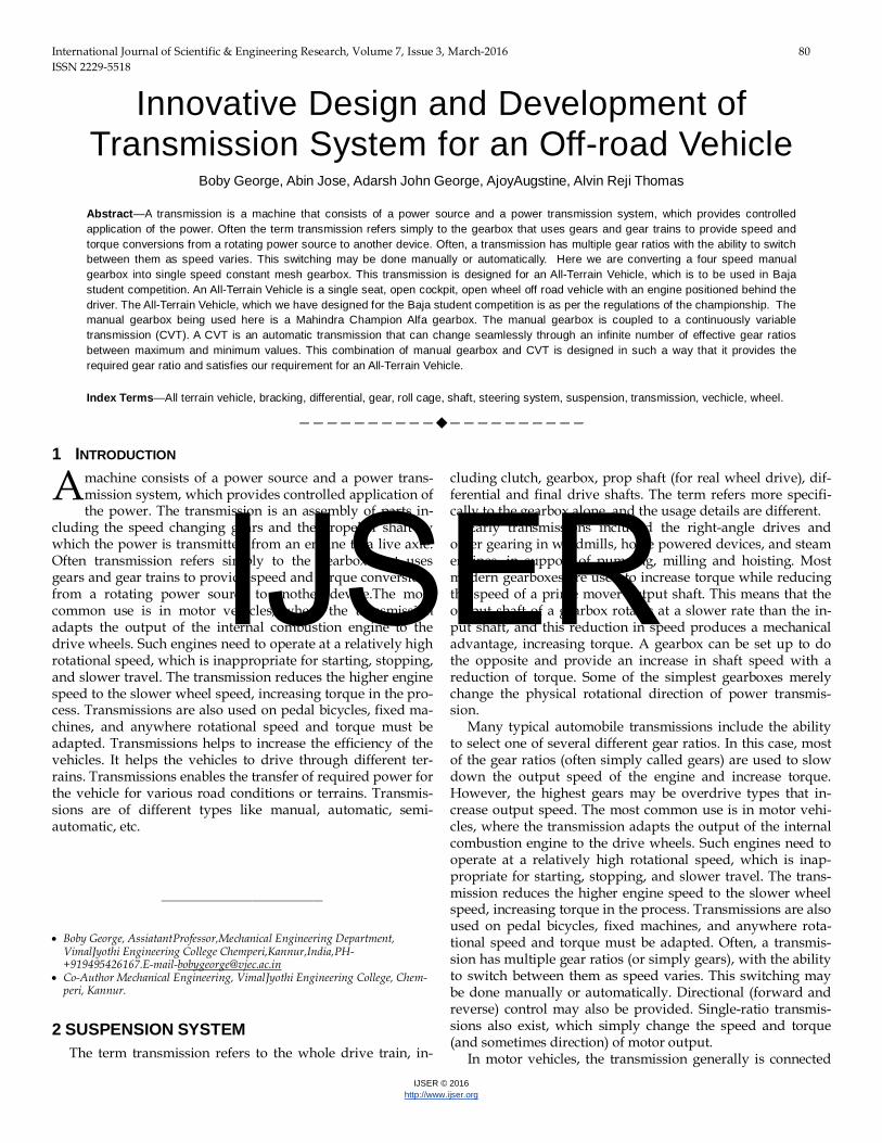
WW >WD, Therefore the design is possible 4.3 Material Selection For getting the suitable stress value we select the material EN24 which is an alloy steel, which consist of Ni, Cr, Mo. This material will provide enough strength to withstand differ-ent stress developed due to the power transmission as per our calculations
5 SHAFT DESIGN For the design of shaft, first we should select the material. Here we use AISI 4340 alloy steel as the shaft material, which has yield strength of 470Mpa and tensile strength of 750Mpa. This is the commonly used material for gear & shaft manufacturing. In order to find the diameter of shaft for spur gears, the following procedure may be followed. 1 First of all, find the normal load (WN), acting between the tooth surfaces. It is given by WN = WT/ cos φ Where, WT = Tangential load φ = Pressure angle. WN = 2400/cos20 = 2554.026 N
2 The weight of the gear is given by WG = 0.00118 TG.b.m2 (in N) Where TG = No. of teeth on the gear, b = Face width in mm, and m = Module in mm. WG = 0.00118 × 31 × 18 × 2.52 =4.11 N 5.3 Now the resultant load acting on the gear, WR= √ (WN2 + WG
2 + 2× WN× WG× cos φ) = √ [(2554.026)2+ (4.11)2+ (2×2554.026×4.11×cos20)] = 2557.88N
4 If the gear is overhung on the shaft, then bending moment on the shaft due to the resultant load, M = WR × x
Where, x = Overhang i.e. the distance between the centre of gear and thecentre of bearing in mm =2557.88 × 40 = 102515.2 Nm
5 Since the shaft is under the combined effect of torsion and bending, therefore we shall determine the equivalent torque. We know that equivalent torque, Te =√ (M2 + T2) where T = Twisting moment = WT × DG/2 = 2400× (82.5/2) =99000 Nm Therefore, Te= √(102515.22+990002) =142514.44 Nm
6 Now the diameter of the gear shaft (d) is determined by using the following relation, i.e. Te = (π/16) × τ × d3 where τ = Shear stress for the mate-rial of the gear shaft =235Mpa 142514.44 = (π/16) ×235×d3 d = 14.56mm
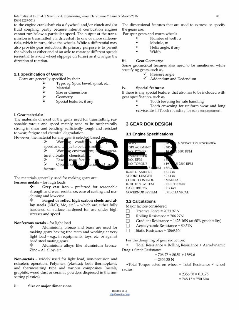
This is the design of input shaft for the gear box. Ie, CVT driven pulley is fixed in the same shaft. It’s inside dia =19.086mm, which is greater than obtained value and also gear casing ar-rangement requires minimum diameter of 30mm. Therefore we fix the shaft diameter as 30mm.
Fig. 3 Manufactured input shaft 6 MANUFACTURE OF GEARS Manufacture of gears need several processing operations in se-quential stages depending upon the material and type of the gears and quality desired. Those stages generally are;
• Preforming the blank with or without teeth • Annealing of the blank, if required, as in case of forged
or cast steels • Preparation of the gear blank to the required dimensions
by machining • Producing teeth or finishing the performed teeth by ma-
chining Full or surface hardening of the machined gear (teeth), if required Finishing teeth, if required, by shaving, grinding, etc.
• Inspection of the finished gears • In this section, performing, producing teeth by machin-
IJSER
International Journal of Scientific & Engineering Research, Volume 7, Issue 3, March-2016 86 ISSN 2229-5518
IJSER © 2016 http://www.ijser.org
ing and gear teeth finishing have been discussed in de-tail.
6.1 Casting
Gear blanks and even gears along with teeth requiring substan-cialto little machining or finishing are produced by various cast-ing process.
I .Sand casting: Sand casting, also known as sand molded casting, is a metal
casting process characterized by using sand as the mold material. The blanks of large cast iron gears, if required to made one or few pieces, are produced by sand casting. Then the blank is pre-pared to appropriate dimensions and the teeth are produced by machining the cast preform. Complete gears with teeth can also be directly produced by such casting and used at low speeds in machineries like farm machinery and hand operated devices where gear accuracy and finish are not that much required.
11. Metal mould casting:
Medium size steel gears with limited accuracy and finish are of-ten made in single or few pieces by metal mould casting. Such unfinished gears are used in several agro industries.For general and precision use the cast preforms are properly machined.
III. Die casting:
Large lot or mass production of small gears of low melting point alloys of Al, Zn, Cu, Mg, etc. are done mainly by die casting. Such reasonably accurate gears are directly or after little further finishing are used under light load and moderate speeds, for ex-ample in instruments, camera, toys.
IV. Investment casting :
This near-net-shape method is used for producing small to medi-um size gears of exotic materials with high accuracy and surface finish hardly requiring further finishing. These relatively costly gears are generally used under heavy loads and stresses.
V. Shell mould casting:
Small gears in batches also often produced by this process. The quality provided by this process lies in between that of sand cast-ing and investment casting.
VI. Centrifugal casting:
The solid blanks or the outer rims of worm wheels made of cast iron, phosphor bronze or even steel are preferably preformed by centrifugal casting. The performs are machined to form the gear blank of proper size. Then the teeth are developed by machining.
6.2 Manufacture of gears by rolling The straight and helical teeth of disc or rod type external steel gears of small to medium diameter and module are generated by cold rolling by either flat dies or circular dies as shown in fig. Such rolling imparts high accuracy and surface integrity of the teeth which are formed by material flow unlike cutting. Gear roll-ing is reasonably employed for high productivity and high quality though initial machinery costs are relatively high. Larger size
gears are formed by hot rolling and then finished by machining.
6.3 Powder metallurgy Small size high quality external or internal spur, bevel or spiral gears are also produced by powder metallurgy process. Large size gears are rolled after briquetting and sintering for more strength and life. Powder metallurgically produced gears hardly require any further finishing work.
6.4 Forming process I. Blanking in press tool
Mass production of small and thin metallic gears requiring less accuracy and finish are often done by blanking from sheets by suitably designed die and punch. Such gears are used for clocks, watches, meters, toys, etc. However, quality gears can also be produced by slight finishing after blanking.
II. Plastic moulding
Small to medium size plastic gears with or without metal core are manufactured in large quantity by injection moulding. Such mod-erately accurate and less noisy gears, both external and internal types, are used under light loads such as equipments, toys, me-ters, etc.
III. Extruction process High quality small metallic or nonmetallic external external gears are often produced in large quantity by extruction. Number of gears of desired width are obtained by parting from the extruded rod of gear section.
6.5 Machining process
1. Gear forming
In gear form cutting, the cutting edge of the cutting tool has a shape identical with the shape of the space between the gear teeth. Two machining operations, milling and broaching can be employed to form cut gear teeth.
2. Form milling
In form milling, the cutter called a form cutter travels axially along the length of the gear tooth at the appropriate depth to pro-duce the gear tooth. After each tooth is cut, the cutter is with-drawn, the gear blank is rotated, and the cutter proceeds to cut another tooth. The process continues until all teeth are cut.
3. Broaching
Broaching can also be used to produce gear teeth and is particu-larly applicable to internal teeth. The process is rapid and pro-duces fine surface finish with dimensional accuracy. However, broaches are expensive and a separate broach is required for each size of gear, this method is suitable mainly for high quantity pro-duction.
IJSER
International Journal of Scientific & Engineering Research, Volume 7, Issue 3, March-2016 87 ISSN 2229-5518
IJSER © 2016 http://www.ijser.org
4. Gear generation In gear generating, the tooth flanks are obtained as an outline of the subsequent positions of the cutter, which resembles in shape the mating gear in the gear pair. There are several modifications of these processes for different cutting tool used.
5. Gear hobbing
Gear hobbing is a machining process in which gear teeth are pro-gressively generated by a series of cuts with a helical cutting tool. All motions in hobbing are rotary, and the hob and gear blank rotate continuously as in two gears meshing until all teeth are cut.
6. FINISHING OPERATIONS
As produced by any of the process described, the surface finish and dimensional accuracy may not be accurate enough for certain applications. Several finishing operations are available, including the conventional process of shaving, and a number of abrasive operations, including grinding, honing and lapping.
7 DIFFERENTIAL
In automobiles and other wheeled vehicles, the differential allows the outer drive wheel to rotate faster than the inner drive wheel during a turn. This is necessary when the vehicle turns, making the wheel that is traveling around the outside of the turning curve roll farther and faster than the other. The average of the rotational speed of the two driving wheels equals the input rotational speed of the drive shaft. An increase in the speed of one wheel is bal-anced by a decrease in the speed of the other. When used in this way, a differential couples the input shaft (or prop shaft) to the pinion, which in turn runs on the crown wheel of the differential. This also works as reduction gearing to give the ratio. On rear wheel drive vehicles the differential may connect to half-shafts inside an axle casing or drive shafts that connect to the rear driv-ing wheels. Front wheel drive vehicles tend to have the pinion on the end of the main-shaft of the gearbox and the differential is enclosed in the same casing as the gearbox. They have individual drive-shafts to each wheel. Older 4x4 vehi-cles and tractors usually have a solid front axle, the modern way can be a separate differential and drive shaft arrangement for the front. A differential consists of one input, the drive shaft, and two outputs which are the two drive wheels, however the rotation of the drive wheels are coupled by their connection to the roadway. Under normal conditions, with small tyre slip, the ratio of the speeds of the two driving wheels is defined by the ratio of the radii of the paths around which the two wheels are rolling, which in turn is determined by the track-width of the vehicle (the dis-tance between the driving wheels) and the radius of the turn.
8 GEARBOX MOUNTING
The gearbox have two main mounting points and two minor mounting points. Here we use two main mounting points. We use
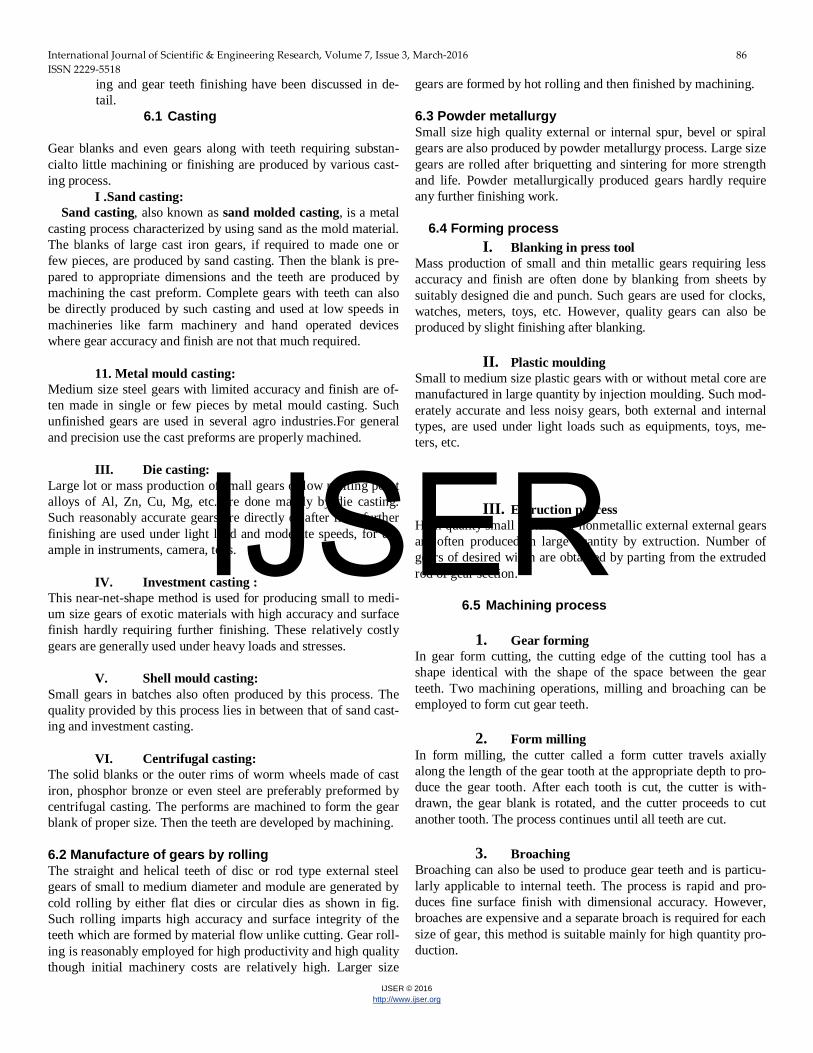
a cross member on the frame to hold the gearbox properly. Since the actual input section of the gearbox is on right side, but in en-gine the output section is in the left side. Therefore due to this constrain we change the direction of input in the gearbox. To change the direction of the input new covering and support will be needed and these must meet the qualities like low weight and withstandable strength. Thus we select the Aluminium T6,6061 material for the design of the casing were selected.On the end casing section we use taper bearing which enables the easy re-moval of the input shaft and on the input side we use normal roll-er bearing.
Fig. 4 Designed and manufactured images of end casing
IJSER
International Journal of Scientific & Engineering Research, Volume 7, Issue 3, March-2016 88 ISSN 2229-5518
IJSER © 2016 http://www.ijser.org
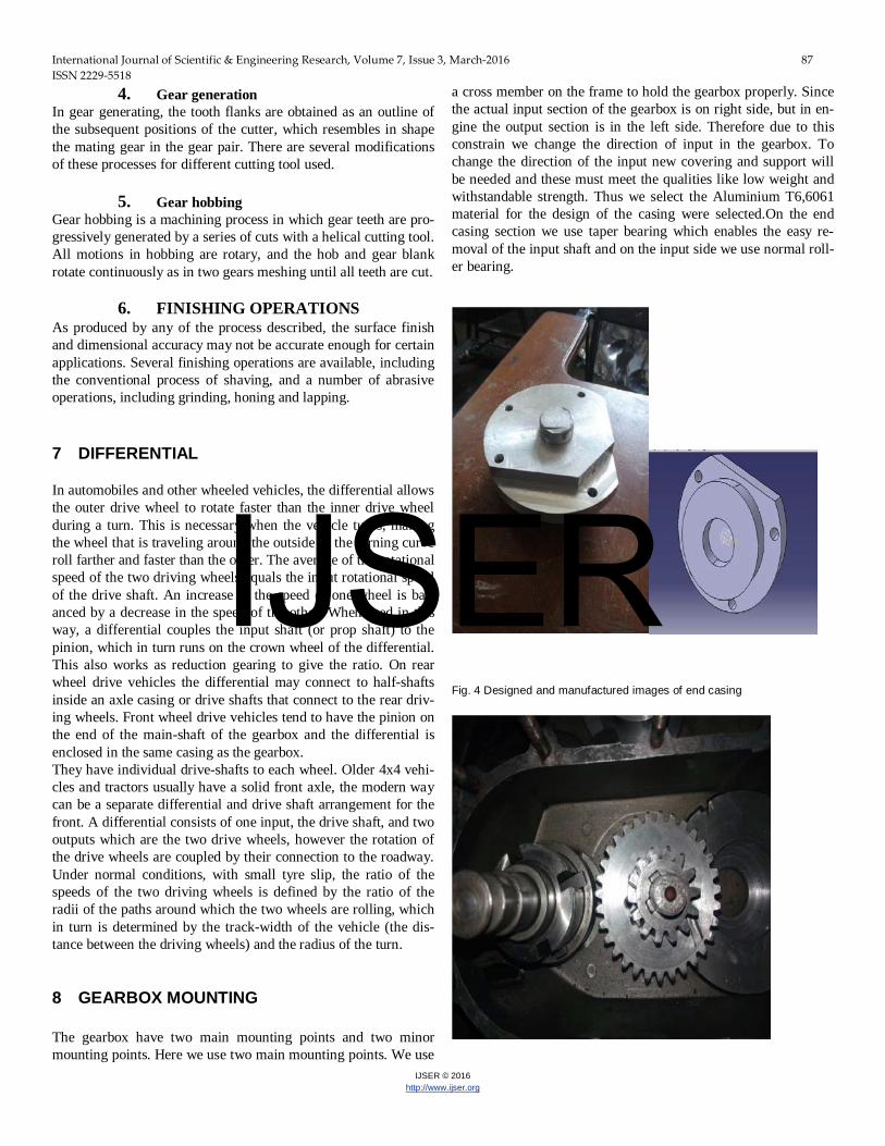
Fig.5 Gear and shaft arrangement in gear box 9 ENGINE MOUNTING
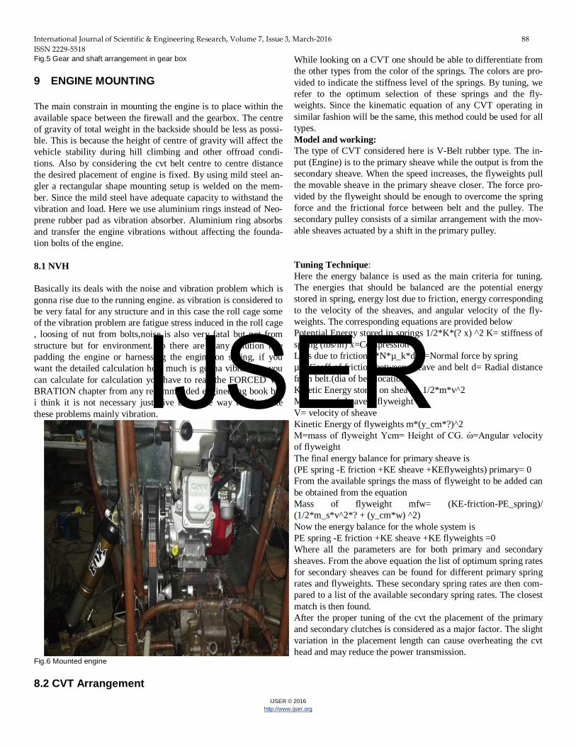
The main constrain in mounting the engine is to place within the available space between the firewall and the gearbox. The centre of gravity of total weight in the backside should be less as possi-ble. This is because the height of centre of gravity will affect the vehicle stability during hill climbing and other offroad condi-tions. Also by considering the cvt belt centre to centre distance the desired placement of engine is fixed. By using mild steel an-gler a rectangular shape mounting setup is welded on the mem-ber. Since the mild steel have adequate capacity to withstand the vibration and load. Here we use aluminium rings instead of Neo-prene rubber pad as vibration absorber. Aluminium ring absorbs and transfer the engine vibrations without affecting the founda-tion bolts of the engine. 8.1 NVH Basically its deals with the noise and vibration problem which is gonna rise due to the running engine. as vibration is considered to be very fatal for any structure and in this case the roll cage some of the vibration problem are fatigue stress induced in the roll cage , loosing of nut from bolts,noise is also very fatal but not from structure but for environment. so there are many solution like padding the engine or harnessing the engine on spring, if you want the detailed calculation how much is gonna vibrate the you can calculate for calculation you have to read the FORCED VI-BRATION chapter from any recommended engineering book but i think it is not necessary just give them the way to eliminate these problems mainly vibration.
Fig.6 Mounted engine
8.2 CVT Arrangement
While looking on a CVT one should be able to differentiate from the other types from the color of the springs. The colors are pro-vided to indicate the stiffness level of the springs. By tuning, we refer to the optimum selection of these springs and the fly-weights. Since the kinematic equation of any CVT operating in similar fashion will be the same, this method could be used for all types. Model and working: The type of CVT considered here is V-Belt rubber type. The in-put (Engine) is to the primary sheave while the output is from the secondary sheave. When the speed increases, the flyweights pull the movable sheave in the primary sheave closer. The force pro-vided by the flyweight should be enough to overcome the spring force and the frictional force between belt and the pulley. The secondary pulley consists of a similar arrangement with the mov-able sheaves actuated by a shift in the primary pulley.
Tuning Technique: Here the energy balance is used as the main criteria for tuning. The energies that should be balanced are the potential energy stored in spring, energy lost due to friction, energy corresponding to the velocity of the sheaves, and angular velocity of the fly-weights. The corresponding equations are provided below Potential Energy stored in springs 1/2*K*(? x) ^2 K= stiffness of spring (lbs/in) x=Compression Loss due to friction 2*N*µ_k*d N=Normal force by spring µk=Coeff of friction between sheave and belt d= Radial distance from belt.(dia of belt location) Kinetic Energy stored on sheaves 1/2*m*v^2 M= mass of sheave + flyweight V= velocity of sheave Kinetic Energy of flyweights m*(y_cm*?)^2 M=mass of flyweight Ycm= Height of CG. ὠ=Angular velocity of flyweight The final energy balance for primary sheave is (PE spring -E friction +KE sheave +KEflyweights) primary= 0 From the available springs the mass of flyweight to be added can be obtained from the equation Mass of flyweight mfw= (KE-friction-PE_spring)/ (1/2*m_s*v^2*? + (y_cm*w) ^2) Now the energy balance for the whole system is PE spring -E friction +KE sheave +KE flyweights =0 Where all the parameters are for both primary and secondary sheaves. From the above equation the list of optimum spring rates for secondary sheaves can be found for different primary spring rates and flyweights. These secondary spring rates are then com-pared to a list of the available secondary spring rates. The closest match is then found. After the proper tuning of the cvt the placement of the primary and secondary clutches is considered as a major factor. The slight variation in the placement length can cause overheating the cvt head and may reduce the power transmission.
IJSER
International Journal of Scientific & Engineering Research, Volume 7, Issue 3, March-2016 89 ISSN 2229-5518
IJSER © 2016 http://www.ijser.org
Fig.7CVT arrangement geometry 9 DESIGN OF DRIVE AXLE Drive axle is major component in the transmission system which is used to transmit the power from the gear box to wheels. In practical situations drive axle causes many problems while in running condition, thus the design needs be done in very careful manner. Since the drive axels undergo torsion, diameter plays a major role in design. For the calculation to obtain the diameter of the drive axle we can use the standard equation T=πτmaxD3/16 Where, τmax= maximum allowable shear stress T= torque transmitted D=diameter of axle Usually we use EN19steel which generally components of medi-ums and large cross section requiring high tensile strength and toughness for automatic engineering, gear and engine construc-tion such as crane shaft steel knocking, connecting roads drive axel etc. It has the chemical composition of, C-0.40% Mn-0.8% Cr-0.95% Mo-0.25% And mechanical Properties: UTSapprox 850 MPa, Yield approx 785 MPa From the calculation part of the gear box design we came to know that the maximum torque transmitted through the shaft is 750 Nm. We also know that yield strength of EN19 steel=785 N/mm2 The drive shaft only meant to transmit the torque ie, only torsion-al stress is transmitted. Hence by using TRESCA theory, we can determine the maximum value of stress, Τmax=σyt/2N Where,σyt= yield strength in N/mm2 N= factor of safety In the case of commercial vehicles generally manufacturers take the factor of safety as 1.5. Therefore, Τmax=785/2×1.5 =261.66 N/mm2 Hence the diameter of shaft can be obtained by,
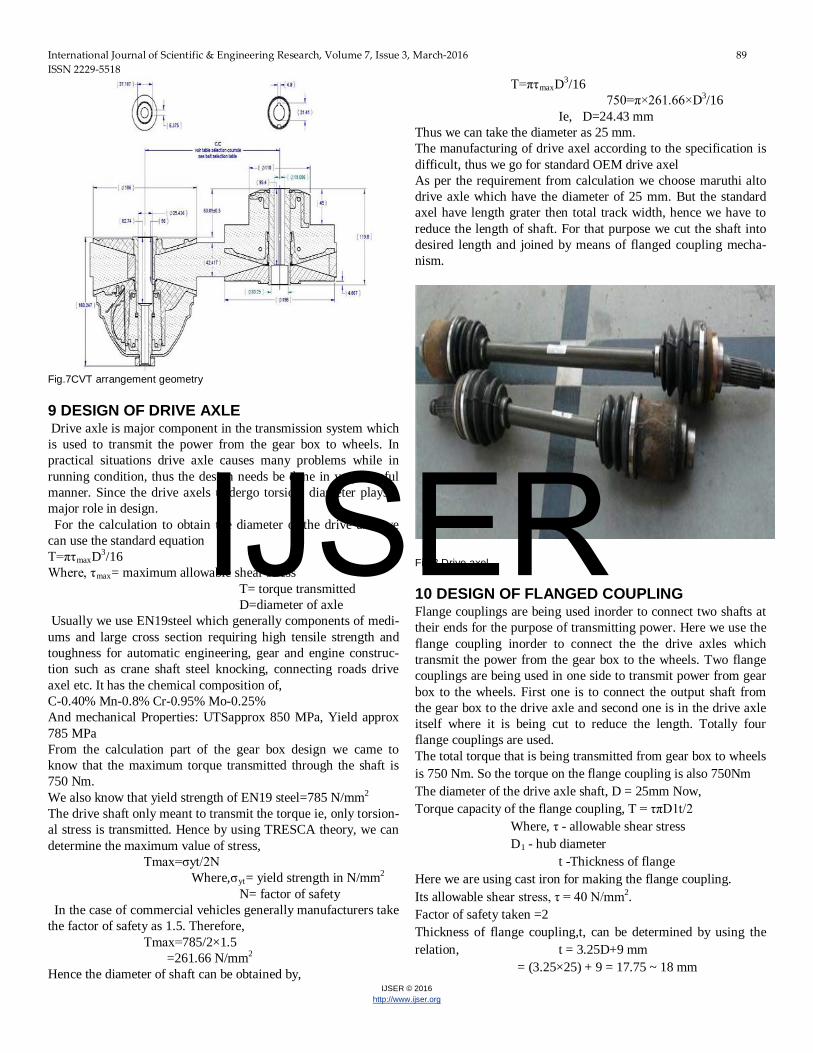
T=πτmaxD3/16 750=π×261.66×D3/16 Ie, D=24.43 mm Thus we can take the diameter as 25 mm. The manufacturing of drive axel according to the specification is difficult, thus we go for standard OEM drive axel As per the requirement from calculation we choose maruthi alto drive axle which have the diameter of 25 mm. But the standard axel have length grater then total track width, hence we have to reduce the length of shaft. For that purpose we cut the shaft into desired length and joined by means of flanged coupling mecha-nism.
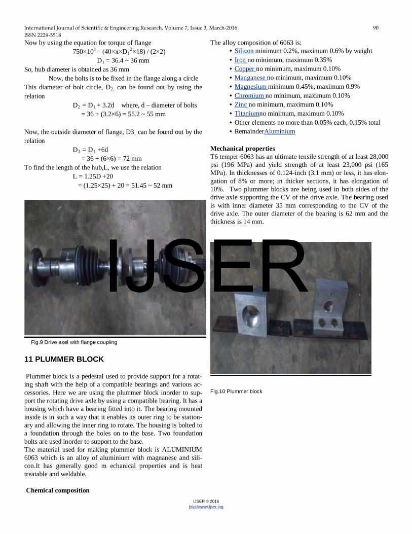
Fig.8 Drive axel 10 DESIGN OF FLANGED COUPLING Flange couplings are being used inorder to connect two shafts at their ends for the purpose of transmitting power. Here we use the flange coupling inorder to connect the the drive axles which transmit the power from the gear box to the wheels. Two flange couplings are being used in one side to transmit power from gear box to the wheels. First one is to connect the output shaft from the gear box to the drive axle and second one is in the drive axle itself where it is being cut to reduce the length. Totally four flange couplings are used. The total torque that is being transmitted from gear box to wheels is 750 Nm. So the torque on the flange coupling is also 750Nm The diameter of the drive axle shaft, D = 25mm Now, Torque capacity of the flange coupling, T = τπD1t/2 Where, τ - allowable shear stress D1 - hub diameter t -Thickness of flange Here we are using cast iron for making the flange coupling. Its allowable shear stress, τ = 40 N/mm2. Factor of safety taken =2 Thickness of flange coupling,t, can be determined by using the relation, t = 3.25D+9 mm = (3.25×25) + 9 = 17.75 ~ 18 mm
IJSER
International Journal of Scientific & Engineering Research, Volume 7, Issue 3, March-2016 90 ISSN 2229-5518
IJSER © 2016 http://www.ijser.org
Now by using the equation for torque of flange 750×103 = (40×π×D1
2×18) / (2×2) D1 = 36.4 ~ 36 mm So, hub diameter is obtained as 36 mm Now, the bolts is to be fixed in the flange along a circle This diameter of bolt circle, D2, can be found out by using the relation D2 = D1 + 3.2d where, d – diameter of bolts = 36 + (3.2×6) = 55.2 ~ 55 mm
Now, the outside diameter of flange, D3, can be found out by the relation D3 = D1 +6d = 36 + (6×6) = 72 mm To find the length of the hub,L, we use the relation L = 1.25D +20 = (1.25×25) + 20 = 51.45 ~ 52 mm
Fig.9 Drive axel with flange coupling
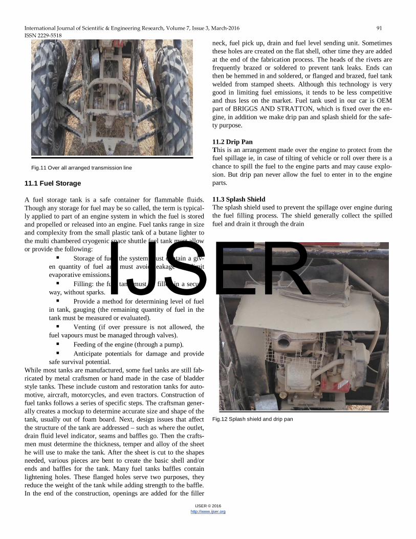
11 PLUMMER BLOCK
Plummer block is a pedestal used to provide support for a rotat-ing shaft with the help of a compatible bearings and various ac-cessories. Here we are using the plummer block inorder to sup-port the rotating drive axle by using a compatible bearing. It has a housing which have a bearing fitted into it. The bearing mounted inside is in such a way that it enables its outer ring to be station-ary and allowing the inner ring to rotate. The housing is bolted to a foundation through the holes on to the base. Two foundation bolts are used inorder to support to the base. The material used for making plummer block is ALUMINIUM 6063 which is an alloy of aluminium with magnanese and sili-con.It has generally good m echanical properties and is heat treatable and weldable.
Chemical composition
The alloy composition of 6063 is: • Silicon minimum 0.2%, maximum 0.6% by weight • Iron no minimum, maximum 0.35% • Copper no minimum, maximum 0.10% • Manganese no minimum, maximum 0.10% • Magnesium minimum 0.45%, maximum 0.9% • Chromium no minimum, maximum 0.10% • Zinc no minimum, maximum 0.10% • Titaniumno minimum, maximum 0.10% • Other elements no more than 0.05% each, 0.15% total • RemainderAluminium
Mechanical properties T6 temper 6063 has an ultimate tensile strength of at least 28,000 psi (196 MPa) and yield strength of at least 23,000 psi (165 MPa). In thicknesses of 0.124-inch (3.1 mm) or less, it has elon-gation of 8% or more; in thicker sections, it has elongation of 10%. Two plummer blocks are being used in both sides of the drive axle supporting the CV of the drive axle. The bearing used is with inner diameter 35 mm corresponding to the CV of the drive axle. The outer diameter of the bearing is 62 mm and the thickness is 14 mm.
Fig.10 Plummer block
IJSER
International Journal of Scientific & Engineering Research, Volume 7, Issue 3, March-2016 91 ISSN 2229-5518
IJSER © 2016 http://www.ijser.org
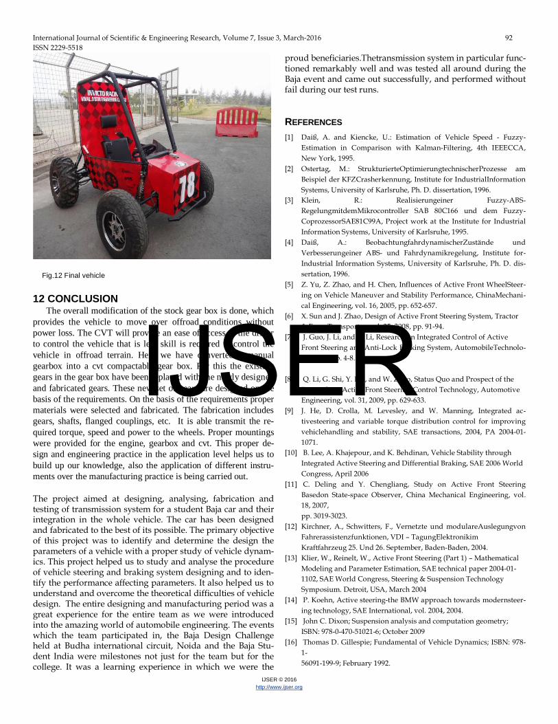
Fig.11 Over all arranged transmission line
11.1 Fuel Storage A fuel storage tank is a safe container for flammable fluids. Though any storage for fuel may be so called, the term is typical-ly applied to part of an engine system in which the fuel is stored and propelled or released into an engine. Fuel tanks range in size and complexity from the small plastic tank of a butane lighter to the multi chambered cryogenic space shuttle fuel tank must allow or provide the following:
Storage of fuel: the system must contain a giv-en quantity of fuel and must avoid leakage and limit evaporative emissions. Filling: the fuel tank must be filled in a secure
way, without sparks. Provide a method for determining level of fuel
in tank, gauging (the remaining quantity of fuel in the tank must be measured or evaluated). Venting (if over pressure is not allowed, the
fuel vapours must be managed through valves). Feeding of the engine (through a pump). Anticipate potentials for damage and provide
safe survival potential. While most tanks are manufactured, some fuel tanks are still fab-ricated by metal craftsmen or hand made in the case of bladder style tanks. These include custom and restoration tanks for auto-motive, aircraft, motorcycles, and even tractors. Construction of fuel tanks follows a series of specific steps. The craftsman gener-ally creates a mockup to determine accurate size and shape of the tank, usually out of foam board. Next, design issues that affect the structure of the tank are addressed – such as where the outlet, drain fluid level indicator, seams and baffles go. Then the crafts-men must determine the thickness, temper and alloy of the sheet he will use to make the tank. After the sheet is cut to the shapes needed, various pieces are bent to create the basic shell and/or ends and baffles for the tank. Many fuel tanks baffles contain lightening holes. These flanged holes serve two purposes, they reduce the weight of the tank while adding strength to the baffle. In the end of the construction, openings are added for the filler
neck, fuel pick up, drain and fuel level sending unit. Sometimes these holes are created on the flat shell, other time they are added at the end of the fabrication process. The heads of the rivets are frequently brazed or soldered to prevent tank leaks. Ends can then be hemmed in and soldered, or flanged and brazed, fuel tank welded from stamped sheets. Although this technology is very good in limiting fuel emissions, it tends to be less competitive and thus less on the market. Fuel tank used in our car is OEM part of BRIGGS AND STRATTON, which is fixed over the en-gine, in addition we make drip pan and splash shield for the safe-ty purpose. 11.2 Drip Pan This is an arrangement made over the engine to protect from the fuel spillage ie, in case of tilting of vehicle or roll over there is a chance to spill the fuel to the engine parts and may cause explo-sion. But drip pan never allow the fuel to enter in to the engine parts. 11.3 Splash Shield The splash shield used to prevent the spillage over engine during the fuel filling process. The shield generally collect the spilled fuel and drain it through the drain
Fig.12 Splash shield and drip pan
IJSER
International Journal of Scientific & Engineering Research, Volume 7, Issue 3, March-2016 92 ISSN 2229-5518
IJSER © 2016 http://www.ijser.org
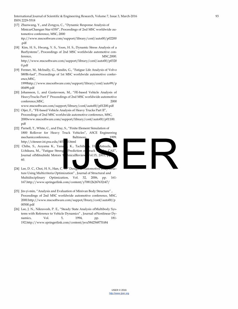
Fig.12 Final vehicle
12 CONCLUSION The overall modification of the stock gear box is done, which provides the vehicle to move over offroad conditions without power loss. The CVT will provide an ease of access to the driver to control the vehicle that is less skill is required to control the vehicle in offroad terrain. Here we have converted a manual gearbox into a cvt compactable gear box. For this the existing gears in the gear box have been replaced with the newly designed and fabricated gears. These new set of gears are designed on the basis of the requirements. On the basis of the requirements proper materials were selected and fabricated. The fabrication includes gears, shafts, flanged couplings, etc. It is able transmit the re-quired torque, speed and power to the wheels. Proper mountings were provided for the engine, gearbox and cvt. This proper de-sign and engineering practice in the application level helps us to build up our knowledge, also the application of different instru-ments over the manufacturing practice is being carried out. The project aimed at designing, analysing, fabrication and testing of transmission system for a student Baja car and their integration in the whole vehicle. The car has been designed and fabricated to the best of its possible. The primary objective of this project was to identify and determine the design the parameters of a vehicle with a proper study of vehicle dynam-ics. This project helped us to study and analyse the procedure of vehicle steering and braking system designing and to iden-tify the performance affecting parameters. It also helped us to understand and overcome the theoretical difficulties of vehicle design. The entire designing and manufacturing period was a great experience for the entire team as we were introduced into the amazing world of automobile engineering. The events which the team participated in, the Baja Design Challenge held at Budha international circuit, Noida and the Baja Stu-dent India were milestones not just for the team but for the college. It was a learning experience in which we were the
proud beneficiaries.Thetransmission system in particular func-tioned remarkably well and was tested all around during the Baja event and came out successfully, and performed without fail during our test runs.
REFERENCES [1] Daiß, A. and Kiencke, U.: Estimation of Vehicle Speed - Fuzzy-
Estimation in Comparison with Kalman-Filtering, 4th IEEECCA, New York, 1995.
[2] Ostertag, M.: StrukturierteOptimierungtechnischerProzesse am Beispiel der KFZCrasherkennung, Institute for IndustrialInformation Systems, University of Karlsruhe, Ph. D. dissertation, 1996.
[3] Klein, R.: Realisierungeiner Fuzzy-ABS-RegelungmitdemMikrocontroller SAB 80C166 und dem Fuzzy-CoprozessorSAE81C99A, Project work at the Institute for Industrial Information Systems, University of Karlsruhe, 1995.
[4] Daiß, A.: BeobachtungfahrdynamischerZustände und Verbesserungeiner ABS- und Fahrdynamikregelung, Institute for-Industrial Information Systems, University of Karlsruhe, Ph. D. dis-sertation, 1996.
[5] Z. Yu, Z. Zhao, and H. Chen, Influences of Active Front WheelSteer-ing on Vehicle Maneuver and Stability Performance, ChinaMechani-cal Engineering, vol. 16, 2005, pp. 652-657.
[6] X. Sun and J. Zhao, Design of Active Front Steering System, Tractor & Farm Transporter, vol. 35, 2008, pp. 91-94.
[7] J. Guo, J. Li, and Y. Li, Research on Integrated Control of Active Front Steering and Anti-Lock Braking System, AutomobileTechnolo-gy, 2007, pp. 4-8.
[8] Q. Li, G. Shi, Y. Lin, and W. Zhao, Status Quo and Prospect of the Research on Active Front Steering Control Technology, Automotive Engineering, vol. 31, 2009, pp. 629-633.
[9] J. He, D. Crolla, M. Levesley, and W. Manning, Integrated ac-tivesteering and variable torque distribution control for improving vehiclehandling and stability, SAE transactions, 2004, PA 2004-01-1071.
[10] B. Lee, A. Khajepour, and K. Behdinan, Vehicle Stability through Integrated Active Steering and Differential Braking, SAE 2006 World Congress, April 2006
[11] C. Deling and Y. Chengliang, Study on Active Front Steering Basedon State-space Observer, China Mechanical Engineering, vol. 18, 2007, pp. 3019-3023.
[12] Kirchner, A., Schwitters, F., Vernetzte und modulareAuslegungvon Fahrerassistenzfunktionen, VDI – TagungElektronikim Kraftfahrzeug 25. Und 26. September, Baden-Baden, 2004.
[13] Klier, W., Reinelt, W., Active Front Steering (Part 1) – Mathematical Modeling and Parameter Estimation, SAE technical paper 2004-01- 1102, SAE World Congress, Steering & Suspension Technology Symposium. Detroit, USA, March 2004
[14] P. Koehn, Active steering-the BMW approach towards modernsteer-ing technology, SAE International, vol. 2004, 2004.
[15] John C. Dixon; Suspension analysis and computation geometry; ISBN: 978-0-470-51021-6; October 2009
[16] Thomas D. Gillespie; Fundamental of Vehicle Dynamics; ISBN: 978-1- 56091-199-9; February 1992.
IJSER
International Journal of Scientific & Engineering Research, Volume 7, Issue 3, March-2016 93 ISSN 2229-5518
IJSER © 2016 http://www.ijser.org
[17] Zhanwang, Y., and Zongyu, C., “Dynamic Response Analysis of MinicarChangan Star 6350”, Proceedings of 2nd MSC worldwide au-tomotive conference, MSC, 2000 ttp://www.mscsoftware.com/support/library/conf/auto00/p02200.pdf
[18] Kim, H. S., Hwang, Y. S., Yoon, H. S., Dynamic Stress Analysis of a BusSystems”, Proceedings of 2nd MSC worldwide automotive con-ference, MSC,2000. http://www.mscsoftware.com/support/library/conf/auto00/p03200.pdf
[19] Fermer, M., McInally, G., Sandin, G., “Fatigue Life Analysis of Volvo S80Bi-fuel”, Proceedings of 1st MSC worldwide automotive confer-ence,MSC, 1999http://www.mscsoftware.com/support/library/conf/auto99/p00499.pdf
[20] Johansson, I., and Gustavsson, M., “FE-based Vehicle Analysis of HeavyTrucks Part I” Proceedings of 2nd MSC worldwide automotive conference,MSC, 2000 www.mscsoftware.com/support/library/conf/auto00/p01200.pdf
[21] Oijer, F., “FE-based Vehicle Analysis of Heavy Trucks Part II”, Proceedings of 2nd MSC worldwide automotive conference, MSC, 2000www.mscsoftware.com/support/library/conf/auto00/p01100.pdf
[22] Parnell, T., White, C., and Day, S., “Finite Element Simulation of 1800 Rollover for Heavy Truck Vehicles”, ASCE Engineering mechanicconference, Baltimore, 1999. http://citeseer.ist.psu.edu/407030.html
[23] Chiba, S., Aoyama K., Yanabu, K., Tachibana, H., Matsuda, K., Uchikura, M., “Fatigue Strength Prediction of Truck Cab by CAE”, Journal ofMitsubishi Motors TechnicalReview, Vol.15, 2003, pp. 54-60.
[24] Lee, D. C., Choi, H. S., Han, C. S., “Design of Automotive Body struc-
ture Using Multicriteria Optimization” , Journal of Structural and Multidisciplinary Optimization, Vol. 32, 2006, pp. 161-167.http://www.springerlink.com/content/y70812k267632r47/
[25] Jin-yi-min, “Analysis and Evaluation of Minivan Body Structure” , Proceedings of 2nd MSC worldwide automotive conference, MSC, 2000.http://www.mscsoftware.com/suppot/lbrary/conf/auto00/p00500.pdf
[26] Lee, J. N., Nikravesh, P. E., “Steady State Analysis ofMultibody Sys-tems with Reference to Vehicle Dynamics” , Journal ofNonlinear Dy-namics, Vol. 5, 1994, pp. 181- 192.http://www.springerlink.com/content/jwu5842568731t84
IJSER