innovative application of dispersed shear wall to a...
TRANSCRIPT
American Journal of Civil Engineering 2016; 4(4): 167-173
http://www.sciencepublishinggroup.com/j/ajce
doi: 10.11648/j.ajce.20160404.16
ISSN: 2330-8729 (Print); ISSN: 2330-8737 (Online)
Innovative Application of Dispersed Shear Wall to a Kilometer-High Concrete Skyscraper
Feroz Alam
Department of Civil Engineering, The Institute of Engineers, Dhaka, Bangladesh
Email address:
To cite this article: Feroz Alam. Innovative Application of Dispersed Shear Wall to a Kilometer-High Concrete Skyscraper. American Journal of Civil
Engineering. Vol. 4, No. 4, 2016, pp. 167-173. doi: 10.11648/j.ajce.20160404.16
Received: April 19, 2016; Accepted: May 23, 2016; Published: June 4, 2016
Abstract: There are numerous structural lateral systems used in high-rise building design such as shear frames, frames with
shear core, framed tubes, tube and tube, super frames etc. Generally, the structural systems of tall buildings are considered to
be two types. One is interior and the other one is exterior type. A system is categorized as an interior structure when the major
parts of the lateral load resisting system are located within the interior of the building. Likewise, if the major parts of the lateral
load resisting system are located at the building perimeter, the system is categorized as an exterior structure. In this study it is
intended to model an advanced structural system which can be applied to buildings taller than the existing tallest building in
the world. In this innovative concept, several parallel shear walls have been arranged in both directions and connected with
beams and R.C. floor slabs. The shear walls are continuous down to the base to which they are rigidly attached to form vertical
cantilevers. Their high in plane stiffness and strength make them well suited for bracing buildings up to about 278 stories.
Fewer widely spaced gravity columns are arranged in the core area of the building to carry floor loads. Because of the absence
of core bracing and of a large number of heavy interior columns, the net leasable area for such a building increases. Static and
Dynamic analysis (Time History Analysis) has been carried out. The drift by static analysis is 1884 mm which is below the
allowable limit of 2001.6mm (If considered H/500, where H is the height of the structure [9]). Also it is found by research that,
when this structural arrangement is applied to around 830 meter tall structure with aspect ratio 9.8:1, no additional structural
supporting system (like Outriggers, Perimeter Belts, Cross Bracing, Tuned Mass Dampers etc.) is required. This shear walls
arrangement is applicable for the tall buildings of any height to avoid additional supports to resist the lateral forces while
taking advantage of the creative approach of this unique concept.
Keywords: Innovative, High-Rise, Dynamic, Drift, Outriggers, Skyscraper
1. Introduction
In the last few decades there has been an enormous
increase in the number of high-rise buildings worldwide. A
tall building is not defined by its height or number of stories.
The important criterion is whether or not the design is
influenced by some aspect ‘’tallness’’. It is a building in
which tallness strongly influences planning, design,
construction and use. It is a building whose height creates
conditions different from those that exist in common
buildings of a certain region and period [7]. There are
physical, code prescribed and practical reasons why tall
buildings tend to be safer than low-rise buildings [8].
Undoubtedly, the factor that governs the design of a tall and
slender structure most of the times is not the fully stressed
state, but the drift/acceleration of the building for wind
loading. It is easy to understand that higher the building, the
more important is the lateral behavior. Thus, to understand
the performance of high-rise buildings, the lateral resisting
system of tall buildings becomes a key factor that needs to be
investigated and understood.
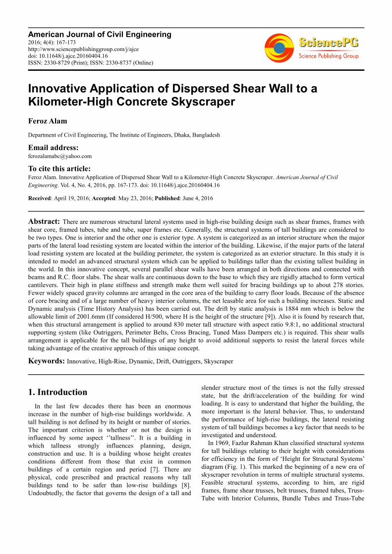
In 1969, Fazlur Rahman Khan classified structural systems
for tall buildings relating to their height with considerations
for efficiency in the form of ‘Height for Structural Systems’
diagram (Fig. 1). This marked the beginning of a new era of
skyscraper revolution in terms of multiple structural systems.
Feasible structural systems, according to him, are rigid
frames, frame shear trusses, belt trusses, framed tubes, Truss-
Tube with Interior Columns, Bundle Tubes and Truss-Tube
168 Feroz Alam: Innovative Application of Dispersed Shear Wall to a Kilometer-High Concrete Skyscraper
without Interior columns [1]. These structural system can
reach up to about 140 stories.
Figure 1. Diagram of Structural Systems by F.R. Khan [1].
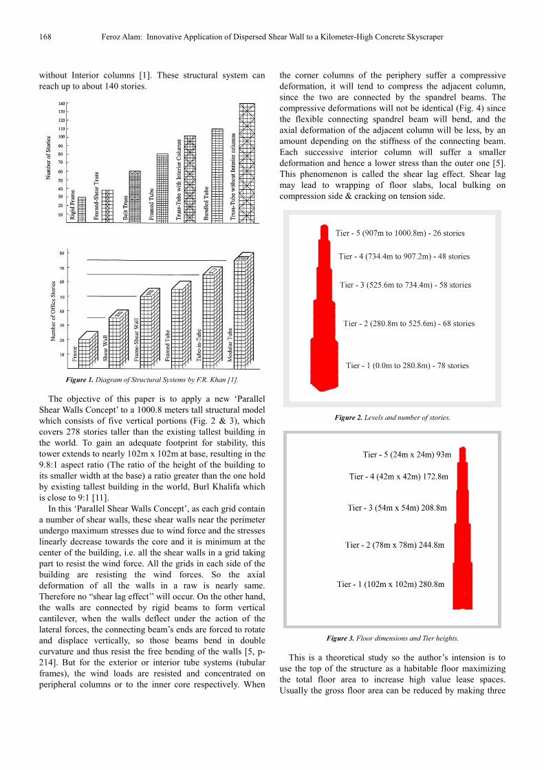
The objective of this paper is to apply a new ‘Parallel
Shear Walls Concept’ to a 1000.8 meters tall structural model
which consists of five vertical portions (Fig. 2 & 3), which
covers 278 stories taller than the existing tallest building in
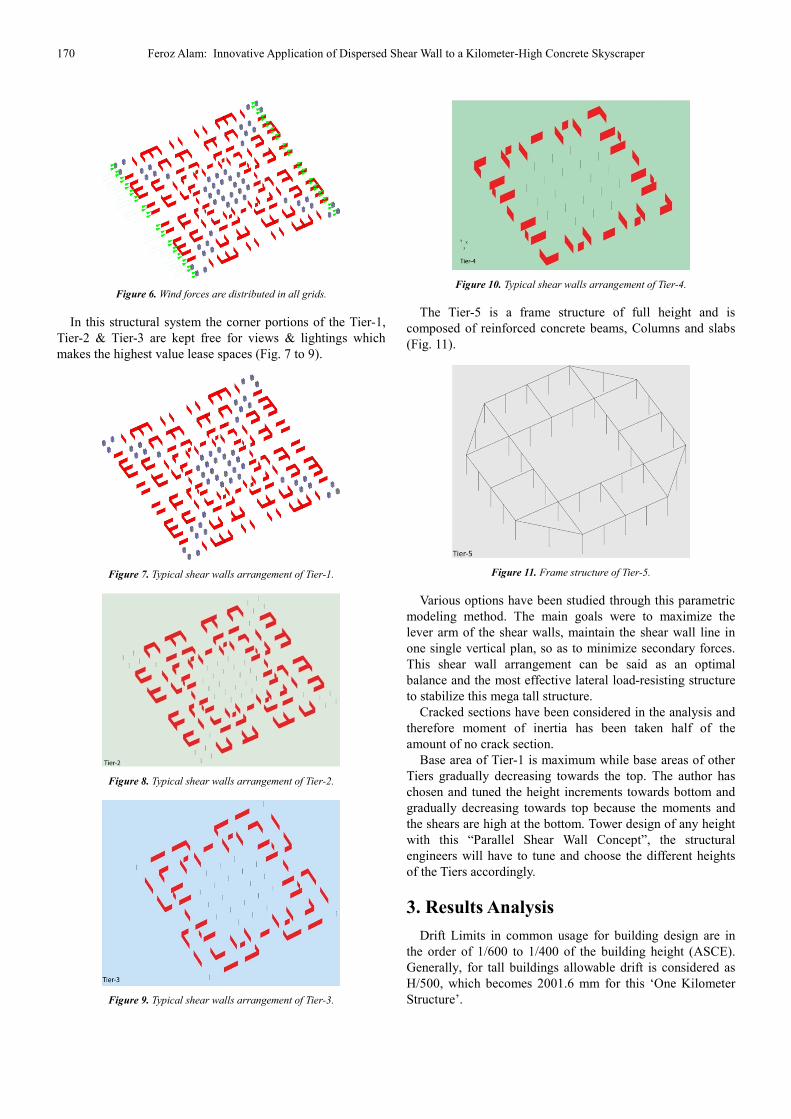
the world. To gain an adequate footprint for stability, this
tower extends to nearly 102m x 102m at base, resulting in the
9.8:1 aspect ratio (The ratio of the height of the building to
its smaller width at the base) a ratio greater than the one hold
by existing tallest building in the world, Burl Khalifa which
is close to 9:1 [11].
In this ‘Parallel Shear Walls Concept’, as each grid contain
a number of shear walls, these shear walls near the perimeter
undergo maximum stresses due to wind force and the stresses
linearly decrease towards the core and it is minimum at the
center of the building, i.e. all the shear walls in a grid taking
part to resist the wind force. All the grids in each side of the
building are resisting the wind forces. So the axial
deformation of all the walls in a raw is nearly same.
Therefore no “shear lag effect’’ will occur. On the other hand,
the walls are connected by rigid beams to form vertical
cantilever, when the walls deflect under the action of the
lateral forces, the connecting beam’s ends are forced to rotate
and displace vertically, so those beams bend in double
curvature and thus resist the free bending of the walls [5, p-
214]. But for the exterior or interior tube systems (tubular
frames), the wind loads are resisted and concentrated on
peripheral columns or to the inner core respectively. When
the corner columns of the periphery suffer a compressive
deformation, it will tend to compress the adjacent column,
since the two are connected by the spandrel beams. The
compressive deformations will not be identical (Fig. 4) since
the flexible connecting spandrel beam will bend, and the
axial deformation of the adjacent column will be less, by an
amount depending on the stiffness of the connecting beam.
Each successive interior column will suffer a smaller
deformation and hence a lower stress than the outer one [5].
This phenomenon is called the shear lag effect. Shear lag
may lead to wrapping of floor slabs, local bulking on
compression side & cracking on tension side.
Figure 2. Levels and number of stories.
Figure 3. Floor dimensions and Tier heights.
This is a theoretical study so the author’s intension is to
use the top of the structure as a habitable floor maximizing
the total floor area to increase high value lease spaces.
Usually the gross floor area can be reduced by making three

American Journal of Civil Engineering 2016; 4(4): 167-173 169
voids from top to bottom on each side of the building
perimeter. These voids will reduce up to 30% from Tier-1,
28% from Tier-2 & 8% from Tier-3. Besides, the central core
area is so far from any natural light at the perimeter, can be a
central void further to reduce the floor area. Because these
voids will not affect the structural behavior as there is no
structural element. The connecting beams have to be in their
own positions.
Figure 4. Axial stress distribution in columns of laterally loaded framed tube
[1].
Table 1. Building’s Data.
Height from ground floor to roof 3282 feet (1000.8 m)
Number of stories 278
Building uses (assumed) Hotel, Office and Residential.
Frame Material Concrete Structure
Typical floor live load 3kn/m2 (60 psf).
Basic wind velocity (100 years
returned period for Qatar, wind load
considered for Qatar, because now
a days middle east has the tendency
to build tall buildings)
41.67 m/sec, (150km/hour).
Allowable Sway (Drift) [9]-
(Commentary Appendix C-Sec:
CC.1.2 ASCE 7-10)
H/500 (H = Height of the Structure)
Allowable Sway at top 1000.8m/500 = 2001.6 mm (6’-6”)
Sway of the Structure at top for
dynamic analysis 1930 mm (6’ - 4”)
Earthquake loading (Not
considered in analysis) -Qatar Z = 0.15, (zone 2A)
Type of structure
Arrangements of Concrete Shear
Walls and Beams for Tier-1, Tier-2,
Tier-3 and Tier-4. Tier-5 is the
frame structure
Foundation Type Future Assignment
Typical Floor height 3.6 m
Floor type R.C.C. Slab
Shear Wall spacing 12m, 9m & 6m c/c
Core area Column-beam framing
Shear Wall thickness at ground
floor
1.6m, 1.5m, 1.4m & 1.3m ,
gradually decreasing the
thicknesses toward top
Typical Beam sizes Depth 0.8 m, Width 1.1m & 1.2 m
Column spacing at base 6m (20 feet) c/c
Column sizes at base 1.5m x 1.5m
Covered area at base by Shear
Walls & Columns 14.53%
Concrete Strength Shear Walls & Columns 80MPa,
Beams & Slab 40MPa
2. Primary Structural Arrangement
The tower is characterized by its symmetry. There are no
transfers of vertical elements through the main body of the
tower. It allows a uniform distribution of gravity forces
through the structure. These characteristics allow for a more
efficient structure.
There is no separation between the gravity system and the
lateral system. The vertical structure is organized in such a
way that the elements are all sized on sufficient lateral
stiffness while at the same time providing strength
consideration. This creates an extremely efficient structure
where the materials perform double-duty (gravity and lateral
support). This structure creates a uniform distribution of load
reducing the differential shortening.
The building has 5 Tiers of different heights (Fig. 2 & 3).
The structural system consists of several parallel shear
walls in each direction of the face of building (Fig. 3 to 9)
which are essentially analogous with the buildings’ central
core columns, coupling beams and conventionally reinforced
concrete floor framing. This produces a completely
interconnected structural system (Fig. 5). The shear wall
arrangements of this tower are in such a way that they
provide large amount of inertia forces and stiffness to the
structure. So the amount of moments carried by the beams
due to wind is less. Therefore the author has selected the
depth of 0.8 m and width 1.1m of all the beams for
theoretical purposes. However, maximum sizes of few beams
will be 1.3m (depth) x 1.4m (width) near the Tier-1 during
practical application as the author checked the maximum
moments.
Figure 5. Floor layout in relation to structure.
Table 2. Drifts at top of the structure.
Height: 1000.8 meters
Drift for Static analysis 1884 mm
Drift for Dynamic analysis 1930 mm
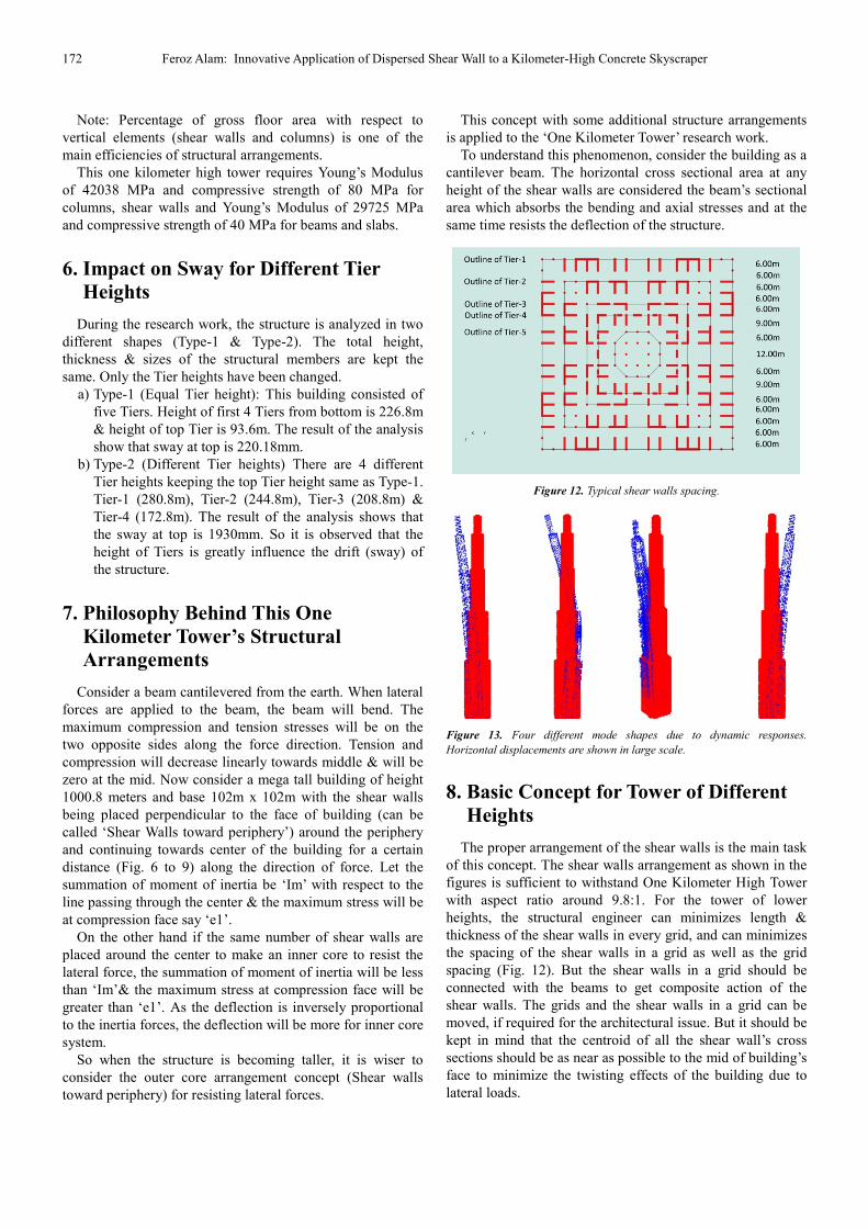
Each side of the building will resist the wind force by
several parallel shear walls. The wind forces will be
distributed to the structure almost uniformly to all grids due
to the shear wall placements (Fig. 6). Each Tier has its own
core which starts from base. Several experiments show that
Tiers with different heights (height of Tier-1 will be longest
and gradually decrease towards top) give better results than
the Tiers of uniform height.
170 Feroz Alam: Innovative Application of Dispersed Shear Wall to a Kilometer-High Concrete Skyscraper
Figure 6. Wind forces are distributed in all grids.
In this structural system the corner portions of the Tier-1,
Tier-2 & Tier-3 are kept free for views & lightings which
makes the highest value lease spaces (Fig. 7 to 9).
Figure 7. Typical shear walls arrangement of Tier-1.
Figure 8. Typical shear walls arrangement of Tier-2.
Figure 9. Typical shear walls arrangement of Tier-3.
Figure 10. Typical shear walls arrangement of Tier-4.
The Tier-5 is a frame structure of full height and is
composed of reinforced concrete beams, Columns and slabs
(Fig. 11).
Figure 11. Frame structure of Tier-5.
Various options have been studied through this parametric
modeling method. The main goals were to maximize the
lever arm of the shear walls, maintain the shear wall line in
one single vertical plan, so as to minimize secondary forces.
This shear wall arrangement can be said as an optimal
balance and the most effective lateral load-resisting structure
to stabilize this mega tall structure.
Cracked sections have been considered in the analysis and
therefore moment of inertia has been taken half of the
amount of no crack section.
Base area of Tier-1 is maximum while base areas of other
Tiers gradually decreasing towards the top. The author has
chosen and tuned the height increments towards bottom and
gradually decreasing towards top because the moments and
the shears are high at the bottom. Tower design of any height
with this “Parallel Shear Wall Concept”, the structural
engineers will have to tune and choose the different heights
of the Tiers accordingly.
3. Results Analysis
Drift Limits in common usage for building design are in
the order of 1/600 to 1/400 of the building height (ASCE).
Generally, for tall buildings allowable drift is considered as
H/500, which becomes 2001.6 mm for this ‘One Kilometer
Structure’.

American Journal of Civil Engineering 2016; 4(4): 167-173 171
The dynamic analysis (Time History Analysis) for wind
has been carried out by STAAD/PRO. Below are the results
for dynamic & static analysis at the top.
SRSS value for six Modes (Square Root of the Sum of
Squares) of dynamic wind analysis is 1995 mm.
Dynamic analysis of this 1 KM tower shows that the
habitable/usable floor is at height 723m (Record breaking
habitable height at 201 story) where acceleration is 30 milli-g
which is acceptable according to NBCC 1990 [3].
Whereas the habitable floor level for the existing tallest
building of the world at the height of 584.5m (154th
Story).
Damping is an important issue as the human comfort due
to excessive acceleration beyond 25 milli-g, in the range of
35 to 50 milli-g, may have to be designed for. Tuned mass
dampers and viscoelastic dampers are often used [10].
Acceleration due to dynamic analysis at top is 47.7 milli-g.
Tuned Mass Dampers (TMDs) transmit inertial force to the
building’s frame to reduce its motion around up to 50%.
Therefore 47.7 milli-g acceleration of this 1 KM high tower
can be reduced by introducing Tuned Mass Damper
accordingly to make this height habitable floor level.
In table-3, there are some examples of tall buildings which
reduced their accelerations by introducing TDMs.
Table 3. Configurations of some TMDs corrently in use.
Host Structure Description Results
Hancock Tower (244m)
in Boston, USA
Two TMDs were
installed at opposite
ends of 58th floor, each
weighing 300 tons.
Can reduce building’s
response 50% [4].
Citicorp Building
(278m) in New York,
USA
A 40 ton concrete block
with two spring
damping mechanisms
installed in 63rd floor
Reduces wind induced
response 40% [4].
Sydney Tower (305m),
Australia
Doughnut-shaped water
tanks & energy
dissipating shock
absorbers.
Response reduced 40-
50% [4].
Sendai AERU (145.5m)
IN Sendai
TMD w/laminated
rubber bearing + coil
spring.
Response reduced ½
[4].
Petronas Twin Tower
(452m) in Kuala
Lumpur
12 Fluid Dampers
Prevent vortex
shedding & reduce
wind-induced
excitation. [4].
Taipei 101 Skyscraper
(509.2m) in Taiwan
Installed world’s largest
& heaviest TDMs
weighing 728 short-ton.
To offset movements in
the building caused by
strong gusts. [6].
Burj Al Arab (321m) in
Dubai Installed 11 TMDs
Reduced wind induced
response. [14]
Vanity/Spire height: In theory, we’re in the midst of a
“golden age’’ of skyscraper construction. But why, of the ten
tallest building on Earth, nearly 30 percent of each structure
totally unusable spire? In truth, this information is readily
available to anyone with eyeballs. All supertalls (e.g, any
building over 1,000 feet tall) have substantial spires and
unoccupied upper floors, which serve to house hardware,
observation decks, and often, mass damper that counter the
sway of the building in the wind. But even taking into
account the necessary infrastructure, the majority of spires
are totally unnecessary.
In fact, without the vanity height, 60 percent of the world’s
supertalls wouldn’t actually be supertalls at all. The burj
Khalifa would lose more than 700 feet. If an angry giant broke
off the Burj’s spire and planted it on the ground, it’d still be the
11th tallest building in Europe. The worst offender of all is the
Burj Al Arab, of which 39 percent is vanity spire [12].
In table 4, there are some examples of vanity height of tall
buildings.
Table 4. Vanity Height of the Towers [13].
Towers Total
Height(Meter)
Vanity Height
(Meter)
Percentage of
vanity height
Zifeng Tower –
China 450 133 30
Bank of America
Tower-New York 366 131 36
Burj Al-Arab-Dubai 321 124 39
Emirates Tower
One-Dubai 355 133 32
New York Times-
New York 319 99 31
Nakheel Tower-
Dubai 1000 N/A 10
If the author add the vanity height (194m) of Burj Khalifa
then author’s 1000.8 meters tower would be 1194.8m.
4. Author's 831 Meters High Tower by
Applying Same Structural
Arrangements (Comparison with the
World’s Existing Tallest Building)
Author’s 1K.m. tower has been reduced to 831.6m tall
(nearly same height of the World's existing Tallest Building).
The 831.6m tower height is achieved by removing 169.2m
from the top of the 1000.8m tower.
Results of the analysis show that drift and acceleration at
831.6m (top) are 1041 mm and 26.9 milli-g (acceptable)
respectively. So the habitable/usable floor is at height 831.6m
(231 stories).Whereas the world tallest building (Burj
Khalifa) will have a drift of 2000 mm [2] at top (828m) and
habitable floor at height 584.5m (154 stories).
5. Covered Vertical Area at Base and
Structural Materials
Area covered by shear walls at ground floor = 1440.24 m2
Area covered by columns at ground floor = 72 m2
Gross area at ground floor = 102m x 102m = 10404 m2
Area covered by vertical elements (shear walls and
columns) at ground floor in percentage
[(1440.2+72)/10404]x100 => 14.53%
172 Feroz Alam: Innovative Application of Dispersed Shear Wall to a Kilometer-High Concrete Skyscraper
Note: Percentage of gross floor area with respect to
vertical elements (shear walls and columns) is one of the
main efficiencies of structural arrangements.
This one kilometer high tower requires Young’s Modulus
of 42038 MPa and compressive strength of 80 MPa for
columns, shear walls and Young’s Modulus of 29725 MPa
and compressive strength of 40 MPa for beams and slabs.
6. Impact on Sway for Different Tier
Heights
During the research work, the structure is analyzed in two
different shapes (Type-1 & Type-2). The total height,
thickness & sizes of the structural members are kept the
same. Only the Tier heights have been changed.
a) Type-1 (Equal Tier height): This building consisted of
five Tiers. Height of first 4 Tiers from bottom is 226.8m
& height of top Tier is 93.6m. The result of the analysis
show that sway at top is 220.18mm.
b) Type-2 (Different Tier heights) There are 4 different
Tier heights keeping the top Tier height same as Type-1.
Tier-1 (280.8m), Tier-2 (244.8m), Tier-3 (208.8m) &
Tier-4 (172.8m). The result of the analysis shows that
the sway at top is 1930mm. So it is observed that the
height of Tiers is greatly influence the drift (sway) of
the structure.
7. Philosophy Behind This One
Kilometer Tower’s Structural
Arrangements
Consider a beam cantilevered from the earth. When lateral
forces are applied to the beam, the beam will bend. The
maximum compression and tension stresses will be on the
two opposite sides along the force direction. Tension and
compression will decrease linearly towards middle & will be
zero at the mid. Now consider a mega tall building of height
1000.8 meters and base 102m x 102m with the shear walls
being placed perpendicular to the face of building (can be
called ‘Shear Walls toward periphery’) around the periphery
and continuing towards center of the building for a certain
distance (Fig. 6 to 9) along the direction of force. Let the
summation of moment of inertia be ‘Im’ with respect to the
line passing through the center & the maximum stress will be
at compression face say ‘e1’.
On the other hand if the same number of shear walls are
placed around the center to make an inner core to resist the
lateral force, the summation of moment of inertia will be less
than ‘Im’& the maximum stress at compression face will be
greater than ‘e1’. As the deflection is inversely proportional
to the inertia forces, the deflection will be more for inner core
system.
So when the structure is becoming taller, it is wiser to
consider the outer core arrangement concept (Shear walls
toward periphery) for resisting lateral forces.
This concept with some additional structure arrangements
is applied to the ‘One Kilometer Tower’ research work.
To understand this phenomenon, consider the building as a
cantilever beam. The horizontal cross sectional area at any
height of the shear walls are considered the beam’s sectional
area which absorbs the bending and axial stresses and at the
same time resists the deflection of the structure.
Figure 12. Typical shear walls spacing.
Figure 13. Four different mode shapes due to dynamic responses.
Horizontal displacements are shown in large scale.
8. Basic Concept for Tower of Different
Heights
The proper arrangement of the shear walls is the main task
of this concept. The shear walls arrangement as shown in the
figures is sufficient to withstand One Kilometer High Tower
with aspect ratio around 9.8:1. For the tower of lower
heights, the structural engineer can minimizes length &
thickness of the shear walls in every grid, and can minimizes
the spacing of the shear walls in a grid as well as the grid
spacing (Fig. 12). But the shear walls in a grid should be
connected with the beams to get composite action of the
shear walls. The grids and the shear walls in a grid can be
moved, if required for the architectural issue. But it should be
kept in mind that the centroid of all the shear wall’s cross
sections should be as near as possible to the mid of building’s
face to minimize the twisting effects of the building due to
lateral loads.
American Journal of Civil Engineering 2016; 4(4): 167-173 173
9. Advantages of This New Structural
Concept
1) The main concept of this system is to place the shear
walls parallel to each other. When wind force is
applied to the structure, each grid (consisting of
several shear walls) will function individually to
resist the wind force of their average span length (See
figure-12). Due to this phenomenon, when this
structural system is subjected to lateral loads such as
wind load, the axial stresses in the shear walls is
nearly linear. Therefore Shear Lag effect is
minimized.
2) Shear walls can be moved on both sides from mid (if
required for architectural demands) by keeping the
area of centroid of the vertical sections at the same
position. This has a negligible effect on the sway.
3) The shear walls are placed almost uniformly over the
base, so the gravity loads are distributed almost
uniformly to all the vertical elements (shear walls).
Therefore reduce the differential settlement.
4) Plenty of natural sunlight will pass through the
building perimeter due to parallel shear wall
arrangements.
5) Simple framing system.
6) No additional lateral load resisting system is required,
like outriggers, belts or cross bracings, except tuned
mass dampers (TMD).
7) Parallel shear walls from both the direction forming a
perpendicular arrangement. “The effect of the
perpendicular walls will be to stiffen the structure in
torsion, to reduce the twist, and, in doing so, to
influence the contributions to the parallel wall shear
and moment that result from the structure’s twisting
[5, page-189].
10. Conclusions
Engineering field professionals are trying to build
buildings taller than the existing tallest ones. Generally these
high-rise buildings require additional lateral systems to
control the drift. But the use of the ‘Parallel Shear Walls’
concept in Skyscraper design is a relatively new idea which
does not take any help of additional lateral systems except
TMD (If the building’s height is above 850 meters). This
structural arrangement can be applied to any tall building of
any height to get a perfect and optimized structure.
The research work carried out on three models of heights
1000.8 meters, 830 meters & 734 meters with this
Structuctural Arrangement. It is observed that the structures
of heights 830 meters & 734 meters have less value for drift
and acceleration than the allowable limits as per International
codes/standards. No bracings, outriggers or damper is
required for such mega tall structures. Only damping system
is required for 1000.8 meters high structure.
That is, this “Innovative Structural Arrangement” is a
simple method to go for tall and mega tall structures.
The details and further analysis of the structural models
are kept (STAAD/PRO software) for further reference, can be
discussed as needed.
Acknowledgement
The research work would not have achieved without the
support, advice and endless effort from my senior colleague
Professor Mr. M Ali, Ph.D., S.E., Fellow ASCE, Fellow
CTBUH, Professor Emeritus of Structure, Adjunct Professor,
University of Illinois at Urbana-Champaign. I am immensely
grateful for the invaluable guidance, support and
encouragement from him. Over the years of my study, I have
benefited greatly from his wisdom and experience. I
sincerely appreciate all the help received from him during the
research work. Comments by the reviewers significantly
contributed to the quality of this paper. I am most grateful to
my brother Filmmaker Mahbubul Alam Taru for formatting
the entire research paper and his encouragement. Finally I
thank to Engr. Anwar Hossain Akon, Engr. Abdullah Al
Mamoon, Chairman IEB Qatar for providing suggestions /
comments on the work.
References
[1] Mir M. Ali (2001). ART OF SKYSCRAPER –THE GENIUS OF FAZLUR KHAN.
[2] Joshua C. Feblowitz. Confusing The Wind: The Burj Khalifa Mother Nature, and the Modern Skyscraper.
[3] Rizk A. S.-CTBUH Technical Paper, Structural Design of Reinforced Concrete Tall Buildings, Published CTBUH Journal issue 1, 2010.
[4] Kareem, Kijewski & Tamura – Mitigation of Motion of Tall Buildings with Specific Examples of Recent Application.
[5] Bryan Stafford Smith & Alex Coull – Tall Building Structures (1991).
[6] Taipei mass damper – Wikipedia, the free encyclopedia.
[7] FRANCIS D. K. – Building Structures Illustrated- Patterns, System, and Design (Second Edition)
[8] Why Tall Buildings Often Considered safer than Low-Rise Buildings During Earthquakes? – CTBUH Journal 2014 Issue III.
[9] ASCE 7-10, Commentary Appendix C, Sec: CC.1.2.
[10] P. Jayachandran, Ph. D, M. ASCE – Design of Tall Buildings– Preliminary Design and Optimization.
[11] Robert Sinn 2012 – Taller: How Future Skyscraper Will Beat the Burj Khalifa.
[12] Kelsey Campbell-Dollaghan – Spire Shame: Why Today’s Tallest Buildings Are Mostly Just Spire.
[13] CTBUH Journal, 2013 Issue III – Tall Buildings in Numbers. Vanity Height: the Empty Space in Todays Tallest.
[14] Tuned mass damper – Wikipedia, the free encyclopedia.