initial performance of advanced designs for ipv nickel ... · in this report advanced designs for...
TRANSCRIPT

- ' # .
NASA Technical Memorandum 87282
Initial Performance of Advanced Designs for IPV Nickel-Hydrogen Cells
U
{NASB- IB-87282) I N I T I A L PEEFCh&AkCE OF N87- 1 € 4 4 5 ACVABCEG DESXGlS EOB IEV N I C K E L - H Y C R O G E N CELLS (NASA) 13 F CSCL 1oc
Unclas G3/44 43321
John J. Smithrick Lewis Research Center Cleveland, Ohio
Prepared for the 15th International Power Sources Symposium Brighton, England, September 7-1 1 , 1986
' '.
,
https://ntrs.nasa.gov/search.jsp?R=19870007012 2018-12-03T13:12:25+00:00Z
INITIAL PERFORMANCE OF ADVANCED DESIGNS
FOR I P V NICKEL-HYDROGEN CELLS*
John J . Smi thr ick Nat ional Aeronautics and Space Admin is t ra t ion
Lewis Research Center Cleveland, Ohio 44135, U.S.A.
SUMMARY
Advanced designs f o r i n d i v i d u a l pressure vessel nickel-hydrogen c e l l s have been conceived which should improve the cyc le l i f e a t deep depths-of- d ischarge and improve thermal management. Features of t he designs which are new and no t incorporated i n e i t h e r of t he contemporary c e l l s ( A i r Force/Hughes, Comsat) are: (1) use of a l t e r n a t e methods of oxygen recombination, (2) use o f
(u ser ra ted edge separators t o f a c i l i t a t e movement o f gas w i t h i n the c e l l w h i l e m m s t i l l ma in ta in ing requ i red phys ica l contact w i t h the w a l l wick, and ( 3 ) use o f
an expandable stack t o accommodate some o f the n i c k e l e lec t rode expansion. Lc! designs a l s o consider e l e c t r o l y t e volume requirements over the l i f e o f t he
c e l l s , and are f u l l y compat ib le w i t h the A i r Force/Hughes design.
I (u The
B o i l e r p l a t e c e l l s based on each o f t he designs have been fabr ica ted . They a r e i n the process o f be ing evaluated i n a con t inu ing cyc le l i f e t e s t . I n i t i a l t e s t r e s u l t s (LEO, 80 percent DOD) demonstrate the f e a s i b i l i t y o f t he designs.
INTRODUCTION
As p a r t o f an o v e r a l l e f f o r t t o advance the technology o f n ickel-hydrogen b a t t e r i e s f o r poss ib le use i n an energy storage system, i n low ea r th o r b i t (LEO), improved advanced designs f o r i n d i v i d u a l pressure vessel (IPV) c e l l s have been conceived (Smi th r i ck e t a l . , 1984). The purpose o f t h i s e f f o r t i s t o improve the cyc le l i f e a t deep depths-of-discharge (DOD) . The approach has been t o e f f e c t c e l l improvements through a con t inu ing combined in-house and con t rac tua l e f f o r t . Contemporary I P V nickel-hydrogen c e l l designs and r e s u l t s o f cyc le l i f e t e s t s conducted In-house and by others were reviewed t o i d e n t i f y areas where improvement could r e s u l t s i n a longer c y c l e l i f e . A component improvement e f f o r t d i r e c t e d towards the phys ica l p roper t i es o f each o f t he i n d i v i d u a l components was i n i t i a t e d and improvements w i l l be fac to red i n t o the c e l l as evolved. and e l e c t r o l y t e management requirements. E x i s t i n g technology was u t i l i z e d where poss ib le t o minimize development cos t and t ime.
Design phi losophies have been developed r e l a t e d t o oxygen
The contemporary design c e l l s ( A i r Force/Hughes, Comsat) a re adequate f o r t he geosynchronous o r b i t (GEO) app l i ca t ions , where n o t many cyc les a re requ i red
4
*This r e p o r t i s an update o f NASA TM-87029.

over the life of the storage system. tions, the current cycle life at deep depths-of-discharge (2000 to 8000 cycles) is not acceptable (Adler et al., 1980; Warnock, 1982). Some investigators report that this limited cycle life is mainly due to degradation of the nickel electrode (Frltts, 1981 a, b; Pickett et al., 1980). However, several failure mechanisms in IPV nickel-hydrogen cells have been Identified which could be eliminated by modification to the SOA cell designs (Smithrick, 1981). modifications have been incorporated into the NASA advanced design IPV nickel- hydrogen cells.
cribed. Initial cycle life performance of boiler plate cells, based on each of these designs, is presented and compared to the Air Force recirculating design.
However, for the demanding LEO applica-
These
In this report advanced designs for IPV nickel-hydrogen cells are des-
EXPERIMENTAL
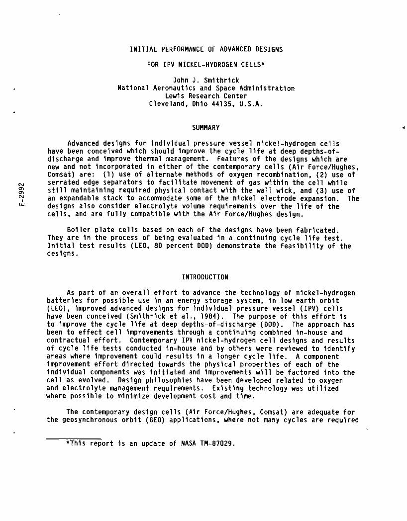
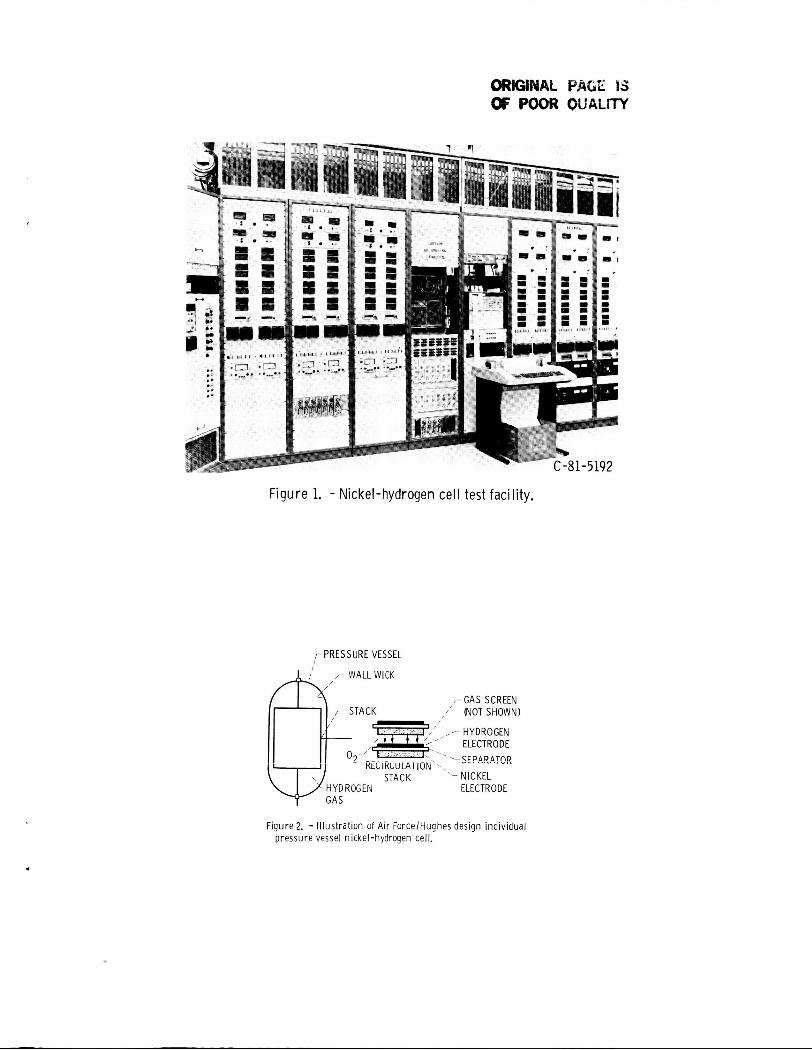
Test Facility
The test facility used to cycle life test the nickel hydrogen cells is illustrated i n figure 1. safety and versatility. hydrogen and also generate hydrogen during charge, special attention was given to personnel safety. cabinets. There were two cells for each cabinet. Each cell was located within a cylindrical shrapnel shield in case of the improbable event of an explosion or rupture of the cell pressure vessel. During a test, the cylindrical shield was purged with nitrogen to create an inert atmosphere. The nitrogen gas, and hydrogen gas if any, would be exhausted from the test laboratory through a hood located above the cells. If the exhaust fan would fail or the nitrogen purge would become interrupted, the test would be automatically terminated. A test can also be terminated on a present upper and/or lower limit of cell vol- tage, current pressure, and temperature.
The facility design incorporates two main features: Since the nickel-hydrogen cells are precharged with
The cells were located on top of the instrumentation
The facility's versatility allows for testing over a wide range of cycle
Various accelerated GEO and low earth orbit regimes. A geosynchronous earth orbit (GEO) cycle regime can be run in real time using a programmable timer. cycle regimes can be run using a Texas Instrument timer. The cell discharge current is controlled by an electronic load, which can be varied from 0 to 100 A. The charge current can also be varied in the same range. Test data are printed out locally using a Fluke data collector. Strip chart recorders are used to record cell voltage, current, and pressure as a continuous function of charge and discharge time for selected cycles. can be tested at the same time.
A maximum for twelve cells
TEST CELL DESCRIPTION
Air Force Design Cell
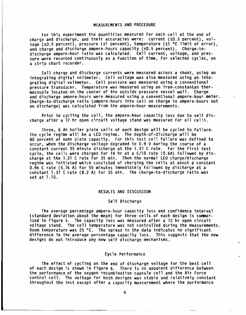
The Air Force cell is illustrated in flgure 2. It consists of a stack of nickel electrodes, separators, hydrogen electrodes, and gas screens assembled in a non back-to-back electrode configuration. The stack is packaged in a cylindrical pressure vessel, with hemispherical end caps. This is made of
2

Inconnel 718 and l i n e d w i t h z i rconium ox ide which serves as a w a l l wick. The components a re shaped i n a "pineapple" s l i c e pa t te rn . The e lect rodes a re con- nected e l e c t r i c a l l y i n p a r a l l e l . I n t h i s con f igu ra t i on e lect rodes o f d i f f e r e n t types d i r e c t l y face each other . Hence, s ince a h igh bubble pressure separator i s used, the oxygen generated a t t he n i c k e l e lec t rode on charge i s d i r e c t e d t o the hydrogen e lec t rode of t he next u n i t c e l l , where i t recombines chemical ly t o form water. The f u e l c e l l grade asbestos separators a re extended beyond the e lect rodes t o contact the w a l l wick. Hence, e l e c t r o l y t e which leaves the stack dur ing c y c l i n g w i l l be wicked back i n t o the stack. The n i c k e l e lec t rode cons is ts o f a s in te red n i c k e l powder plaque conta in ing a n i c k e l screen sub- s t r a t e which i s e lec t rochemica l l y impregnated w i t h n i c k e l hydroxide a c t i v e ma te r ia l by the P i c k e t t process. The gas screens are polypropylene. The e l e c t r o l y t e i s a 31 percent aqueous s o l u t i o n o f potassium hydroxide. The stack con f igu ra t i on i s r e f e r r e d t o as a r e c i r c u l a t i n g design.
NASA ADVANCED CELLS
Overa l l Des i gn
Two d i f f e r e n t bu t s i m i l a r advanced design I P V nickel-hydrogen c e l l s have been conceived. They are i l l u s t r a t e d i n f i g u r e s 3 and 4. One i s r e f e r r e d t o as the cata lyzed w a l l wick and the other as the oxygen recombination capsule design. I n i t i a l l y the n i c k e l e lectrodes, hydrogen electrodes, gas screens, pressure vessel, and potassium hydroxide e l e c t r o l y t e concentrat ion w i l l be i d e n t i c a l t o the ones used i n the s ta te -o f - the-ar t A i r Force/Hughes c e l l s . However, a component improvement e f f o r t d i r e c t e d towards the phys ica l proper- t i e s o f each o f the i n d i v i d u a l components has been i n i t i a t e d and improvements w i l l be fac to red i n t o the c e l l s as they evolve. For both designs the e lec t rode con f igu ra t i on i s back-to-back as i s the case f o r the Comsat c e l l . Both designs a l s o use a w a l l wick, however por t ions o f the w a l l wick a re cata lyzed f o r t he cata lyzed w a l l wick design.
Features of t he advanced designs which are new and no t incorporated i n e i t h e r o f the contemporary c e l l s are: (1 ) use o f a l t e r n a t e methods o f oxygen recombination; ( 2 ) use o f serrated edge separators; and ( 3 ) use o f an expand- ab le s tack. The designs a l s o consider e l e c t r o l y t e volume requirements over the l i f e of the c e l l s , and are f u l l y compat ib le w i t h the A i r Force/Hughes design.
B o i l e r p l a t e c e l l s o f both designs a re i n the process o f being cyc le tes ted t o v e r i f y design f e a s i b i l i t y .
Oxygen Management
Dur ing the l a t e r p a r t o f charge and on overcharge oxygen i s evolved a t the n i c k e l e lect rodes. For both contemporary designs oxygen management con- s i s t s o f chemical ly recombining the oxygen generated du r ing charge on cata lyzed hydrogen e lec t rode sur face t o f o r m w a t e r . This chemical reac t i on i s very exo- thermic; hence care must be taken t o l i m i t t he r a t e a t which these two reac- t a n t s come together . I f a separator i s used which has a pore s i z e d i s t r i b u t i o n t h a t permi ts a c e r t a i n degree o f gas permeab i l i t y , oxygen bubble bu i l dup occurs and ttpoppingll r e s u l t s as these accumulations o f oxygen ab rup t l y recombine. This can r e s u l t i n s i n t e r i n g o f the catalyzed surface and/or l o c a l m e l t i n g o f

the Tef lon/catalyzed agglomeration t h a t makes up the hydrogen e lec t rode. If high bubble pressure separators a re used i n the back-to-back e lec t rode con- f i g u r a t i o n (Comsat design) the oxygen must t r a v e l a long the face o f t he n i c k e l , leave the stack, and then reenter t o recombine on the hydrogen e lec t rode. I n t h i s case, t he recombination would be expected t o take p lace around the ou ter per imeter o f the e lect rodes. The concent ra t ion o f chemical reac tan ts could r e s u l t i n damage t o t h e e l e c t r o c a t a l y s t sur face o f t h e e lec t rode.
An improved method o f oxygen recombinat ion i s t o use a cata lyzed w a l l wick. i s d i r e c t e d t o the cata lyzed w a l l wick where i t recombines. i s wicked i n t o the stack because the asbestos separators a re i n contac t w i t h the w a l l wick. An oxygen seal i s used a t t he i nne r edge o f t h e n i c k e l e lec- t rodes t o preclude oxygen from bypassing the cata lyzed w a l l wick by escaping i n t o the stack core, and reen te r ing t o recombine a t t h e hydrogen e lect rodes. The asbestos separator pore s i z e d i s t r i b u t i o n i s such t h a t i t has a h igh bubble pressure, thus denying the oxygen a d i r e c t pa th t o the hydrogen e lec t rode.
The oxygen evolved on charge between the back-to-back n i c k e l e lect rodes The water formed
The catalyzed w a l l wick i s f ab r i ca ted by f i r s t depos i t i ng a t h i n z i r - conium ox ide layer o f w ick ing ma te r ia l on the inner sur face o f the pressure vessel, as i s the case i n the A i r Force design. A p la t inum Tef lon m ix tu re I s coated i n s t r i pes onto the z i rconium oxide sur face. The m ix tu re i s s i m i l a r t o t h a t used t o fab r i ca te SOA hydrogen e lect rodes, and i s cured i n the same manner.
The advantages o f us ing a catalyzed w a l l wick are: (1 ) a ids thermal management, as the heat o f oxygen recombination i s deposi ted a t t he pressure vessel w a l l ra ther than a t the hydrogen e lect rodes i n the stack, and ( 2 ) pre- vents damage t o t h e hydrogen e lec t rode due t o concentrated bubbles o f oxygen reac t i ng (popping problem).
Another method o f oxygen management would be t o use oxygen recombinat ion capsules between the back-to-back n i c k e l e lect rodes. The h igh bubble pressure asbestos separator d i r e c t s the oxygen i n t o the capsule, which cons is ts o f recombination s i t e s cata lyzed w i t h p la t inum. vapor permeable coa t ing t o a l l o w passage o f t he gases i n and water vapor out , bu t remain hydrophobic t o l i q u i d . The coat ing must a l s o i s o l a t e the c a t a l y s t e l e c t r i c a l l y , otherwise i t w i l l r eac t w i t h the n i c k e l e lec t rode as a p a r a s i t i c reac t i on . The water formed w i t h i n the capsule I s re turned t o the n i c k e l e lec- t rodes I n the vapor form. This method o f oxygen management b e n e f i t s t he over- a l l e l e c t r o l y t e management scheme, and helps prevent damage t o the hydrogen e lect rode.
They a re encapsulated w i t h a
Expandable Stack
The SOA e lect rochemical ly impregnated n i c k e l e lect rodes expand s i g n i f i - c a n t l y due t o cyc l i ng a t deep depths-of-discharge compressing the separators. The e l e c t r o l y t e forced out i s absorbed by the increased pore volume of the n i c k e l e lectrodes. Hence, expansion of the n i c k e l e lec t rodes e f f e c t s e l e c t r o - l y t e volume (as a percentage o f stack sa tu ra t i on ) and e l e c t r o l y t e d i s t r i b u t i o n . This f a i l u r e mode app l ies t o t he Comsat c e l l , which does no t use a r e c i r c u l a - t i o n stack. maintained by the r e c i r c u l a t i o n stack design. by others t h a t the A i r Force c e l l has a l s o f a i l e d due t o n i c k e l e lec t rode expansion (Mul ler , 1984). I n t h i s case, the expansion was so grea t (about
I n t h e A i r Force c e l l , the proper e l e c t r o l y t e volume should be However, i t has been repor ted
4

1/2 in . , 40 e lec t rode s tack) t h a t the polysul fone core o f t he stack ruptured. This f a i l u r e mode can be e l imtnated by modi fy ing the c e l l design t o accommodate expans 1 on.
To accommodate the n i c k e l e lect rode expansion and improve cyc le l i f e , an expandable stack has been proposed. Income1 718 B e l l e v l l l e d i sc spr ings a t each end o f the stack between the end p la tes and t i e rod nuts. The spr ings w i l l ma in ta in stack compression through- ou t t he l i f e o f the c e l l and a l so accommodate expansion. share the accommodation w i t h the separator. The spr ing constant can be selec- t ed so t h a t some o f the e lec t rode expansion i s absorbed by the asbestos sepa- r a t o r . nickel-hydrogen c e l l s , can be compressed t o about 5 m i l w i thou t any performance degradat ion provided I t has adequate e l e c t r o l y t e . I n SOA c e l l s , the asbestos separators a re i n i t i a l l y compressed 1 m i l t o i nsu re good component contact . As a mat te r o f f a c t , t he performance o f t he separator may improve due t o the decrease i n th ickness. due t o compression. w i t h t h e B e l l e v i l l e spr ing. t i v e sp r ing constants.
One way of implementing t h i s i s t o use
Another way i s t o
A 10 m i l separator, which l s the standard th ickness used i n contemporary
However, t h i s could be o f f s e t by a change i n t o r t u o s i t y
The r e l a t i v e d e f l e c t i o n w i l l depend on the respec- The separator can be thought o f as a spr ing i n ser ies
An e f f o r t has been i n i t i a t e d In-house t o I n v e s t i g a t e the e f f e c t o f sepa- r a t o r compression on res is tance and e l e c t r o l y t e content .
Serrated Separator
The separators a re made o f beater t rea ted asbestos (BTA) ra the r than con- vent iona l f u e l c e l l grade asbestos. BTA i s r econs t i t u ted f u e l c e l l grade asbestos t h a t has 5 percent by weight b u t y l l a t e x b inder added (Schmidt e t a l . , 1981). The sheet i s formed i n 1 p l y and i s approximately 7 m i l t h i c k . The p roper t i es o f BTA a re comparable t o those o f t he f u e l c e l l grade asbestos ( r e s i t i v i t y , e l e c t r o l y t e re ten t i on , poros i ty , pore s ize, and bubble pressure). I n add i t ion , t he BTA i s more un i fo rm and s t ronger . The edges o f t h e separator a re serrated t o f a c i l i t a t e gas movement i n s i d e the c e l l . The duty cyc le o f t he s e r r a t i o n i s about 25 percent. Hence, 7 5 percent o f the separator edge w i l l s t i l l be i n contac t w i t h the pressure vessel w a l l f o r e l e c t r o l y t e manage- ment.
E l e c t r o l y t e Management
C e l l performance i s very sens i t i ve t o stack e l e c t r o l y t e volume d i s t r i b u - t i o n (Abbey e t a l . , i 9 8 2 ) . and some are d i f f i c u l t t o c o n t r o l . However, by good design, proper e l e c t r o l y t e volume can be maintained over the l i f e o f the c e l l f o r good performance.
There are many f a c t o r s which e f f e c t t h i s quan t i t y ,
One way o f ma in ta in ing the proper e l e c t r o l y t e volume i s t o p rov ide e x t r a e l e c t r o l y t e i n the bottom o f t he c e l l (about 20 m i l ) and a means o f t ranspor t - i n g i t t o the stack as requi red. Thls can be done by extending the separators beyond the e lect rodes t o contac t t he wa l l wick, which i s i n contac t w i t h t h e e l e c t r o l y t e rese rvo i r , as i s t he case i n the A i r Force design.
5
MEASUREMENTS AND PROCEDURE
For this experiment the quantities measured for each cell at the end of charge and discharge, and their accuracies were: tage (20.5 percent), pressure (21 percent), temperature (21 OC limit of error), and charge and discharge ampere-hours capacity (k0.5 percent). discharge ampere-hour ratio was calculated. Cell current, voltage, and pres- sure were recorded continuously as a function o f time, for selected cycles, on a strip chart recorder.
current (20.3 percent), vol-
Charge-to-
Cell charge and discharge currents were measured across a shunt, using an Integrating digital voltmeter. Cell voltage was also measured using an inte- grating digital voltmeter. pressure transducer. Temperature was measured using an Iron-constantan ther- mocouple located on the center of the outside pressure vessel wall. and discharge ampere-hours were measured using a conventional ampere-hour meter Charge-to-discharge ratio (ampere-hours into cell on charge to ampere-hours out on discharge) was calculated from the ampere-hour measurements.
Cell pressure was measured using a conventional
Charge
Prior to cycling the cell, the ampere-hour capacity loss due to self dis- charge after a 72 hr open circuit voltage stand was measured for all cells.
Three, 6 Ah boiler plate cells of each design will be cycled to failure.
For this test cell failure was defined to The cycle regime will be a LEO regime. The depth-of-discharge will be 80 percent of name plate capacity. occur, when the discharge voltage degraded to 0.9 V during the course of a constant current 35 minute discharge at the 1.37 C rate. cycle, the cells were charged for 18 hr at a C/10 rate (0.6A) followed by dis- charge at the 1.37 C rate for 35 min. Then the normal LEO charge/discharge regime was initiated which consisted of charging the cells at about a constant 0.96 C rate (5.76 A ) for 55 minutes immediately followed by discharge at a constant 1.37 C rate (8.2 A) for 35 min. The charge-to-discharge ratio was set at 1.10.
For the first test
RESULTS AND DISCUSSION
Self Discharge
The average percentage ampere-hour capacity loss and confidence interval (standard deviation about the mean) for three cells of each design is summar- ized in figure 5. The capacity loss was measured after a 72 hr open circuit voltage stand. The cell temperature was not controlled during the measurements. Room temperature was 25 OC. The spread i n the data indicates no significant difference in the average percentage capacity loss. This suggests that the new designs do not introduce any new self discharge mechanisms.
Cycle Performance
The effect of cycling on the end of discharge voltage for the best cell of each design Is shown in figure 6. There is no apparent difference between the performance of the oxygen recombination capsule cell and the A i r Force control cell. The voltage for both designs was stable and relatively constant throughout the test except after a capacity measurement where the performance
6

improved for both designs. 1.14 V for each design cell. a lower than expected end of discharge voltage. low voltage could be inadequate electrolyte. To verify this, the cell was taken off test at cycle 200, vacuum filled with electrolyte, and stored at open circuit voltage for 20 days. cell was placed back on test. on the cell performance was dramatic. The end of discharge voltage increased from 0.82 to 1.17 V. The voltage leveled off at about 1.14 V and remained relatively constant. Hence after vacuum filling wlth electrolyte there is no apparent difference between the performance of the catalyzed wall wick cell and the Air Force control cell.
At cycle 3600 the end of discharge voltage is about The catalyzed wall wick cell initially exhibited
One possible cause for this
After the open circuit voltage stand the The effect of vacuum filling wlth electrolyte
At cycle 2000 the voltage remains at about 1.14 V .
The cycle test of these cells will be continued until failure. A post- cycle cell teardown and failure analysis will be conducted to evaluate the cause(s) for failure. This information will be used to further improve the cell designs.
CONCLUDING REMARKS
Advanced designs for IPV nickel-hydrogen have been conceived, which could have a longer cycle llfe at deep depths-of-discharge and improved thermal man- agement. The features of the designs which are new are: use of alternate methods of oxygen recombinations, use of an expandable stack to accommodate nickel electrode expansion, and use of serrated edge separators to facilitate gas movement within the cell while still maintaining required physical contact with the wall wick. The designs also consider electrolyte volume requirements over the life of the cells, and are fully compatible wlth the Air Force/Hughes design.
Boiler plate cells based on each of the designs have been fabricated and are in the process of being evaluated in a continuing cycle life test. Initial results indicate the feasibility of the design.
REFERENCES
Abbey, K.M. and Britton, D.L. (1982). NASA TM-83073, : "Electrolyte Manage- ment in Porous Battery Components-Static Measurement in Porous Battery Components-Static Measurements."
Adler, E. et ai. (1480). iiNickel-Hyarogen Battery Advanced Development Program." AFWAL-TR-80-2044.
Fritts, D.H. (1981). "A Discussion of the Causes of Blistering of Sintered Nickel Hydroxide Electrodes." Journal of Power Sources, Vol. 6, pp. 327-336.
Fritts, D.H. (1981). "Testing the Mechanical Characteristics of Sintered Nickel Battery Plaque and Their Relationship to Nickel Electrode Performance.' Journal of Power Sources, Vol. 6, pp. 171-184.
Mueller, V.C.: (1984). "Failure Analysis of Nickel-Hydrogen Cell Subjected to Simulated Low Earth Orbit Cycling." NASA CP-2331, pp. 523-538.
7
Pickett, D.F. et al. (1980). Long Life Nickel Oxide Electrodes for Nickel-Hydrogen Cells.Il 21st Century, Vol. 3, AIAA, New York, pp. 1918-1924.
"Establishment of Parameters for Productlon of Energy to the
Schmidt, G.F. and Weber, R.E. (1981). "Development of Battery Separator Composites." NASA CR-165508.
Smithrick, J.J. (1983). "Cycle Life Test and Failure Model of Nickel-Hydrogen Cells: Energy for the Marketplace, Vol. 4, AIChE, New York, pp. 1535-1542.
Smithrick, J.J. et al. (1984). "Advanced Designs for IPV Nickel-Hydrogen Cells.: Advanced Energy Systems-Their Role i n Our Future. Vol. 1, American Nuclear Society, pp. 631-635.
Warnock, D . (1982). ''Life Test of 50 AH NIH2 Battery." The 1981 Goddard Space Flight Center Battery Workshop, 6. Halpert, ed., NASA CP-2277, pp. 487-500.
8
,
Figure 1. - Nickel-hydrogen cell test facility.
,-PRESSURE VESSEL i A,,,- WALL WICK
r G A S SCREEN /' OVOT SHOWN)
,-HYDROGEN ELECTRODE
'- '-CFPADATnD --' '"""""
ELECTRODE
KtLlKLULAl ION STACK NICKEL
Figure 2. - I l l us t ra t i on of A i r Force lHughes des ign ind iv idual p ressu re vessel nickel-hydrogen cell.

~ CELLFEATURES
GAS MOVEMENT
ACCOMMODATE NICKEL ELECTRODE EXPANSION
-CATALYZED WALL WICK-
*EXPANDABLE STACK- 7 8
1 BELLEVILLE SPRING 2 NICKEL ELECTRODE 3 SEPARATOR 4 HYDROGEN ELECTRODE 5 GAS SCREEN 6 WALL WICK 7 OXYGEN SEAL 8 END PLATE 9 CATALYZED STRIP
10 ZIRCONIUM OXIDE STRIP
OXYGEN MANAGEMENT
*ELECTROLYTE VOLUME TOLERANCE-MAINTAIN PROPER STACK ELECTROLYTE BACK-TO-BACK ELECTRODES-DIRECT OXYGEN TO CATALYZED WALL WICK
-COMPATIBLE WITH SOA AIR FORCElHUGHES
DEVELOPMENT COST AND TIME
DESIGN-MINIMIZE
Figure 3. - N A S A advanced design IPV nickel-hydrogen cell-catalyzed wa l l wick.
- 6 - 7 - 8
- 9
- 10 ---
u 1 NICKEL ELECTRODE 2 OXYGEN RECOhlBINATION UNIT 3 GAS SCREEN - POLYPROPYLENE 4 SEPARATOR - BEATER TREATED ASBESTOS 5 HYDROGEN ELECTRODE 6 ELECTRICAL LEADS 7 PRESSURE VESSEL 8 BELLEVILLE SPRING 9 WALL WICK
10 STACK
F igure 4. - NASA advanced design nickel-hydrogen ce l l - oxygen recombinat ion capsule.

CELL DESIGN AIR FORCE w
CATALYZED WALL WICK w OXYGEN RECOMBINATION CAPSULE
I I I I I I I I I I 1 ll 4 8 12 16 20 24 28 32 M 40
Figure 5. - Self discharge - average capacity loss and confidence inter-
AMPERE-HOUR CAPACITY LOSS, PERCENTAGE
val after 72 hr open circuit voltage stand.
CELL DESIGN 0 OXYGEN RECOMBINATION CAPSULE A CATALYZED WALL WICK 0 AIR FORCE
L” 0 1.4 1 PERFORMANCE AFTER ELECTROLME REFILL n 2 PERFORMANCE AFTER CAPACITY MEASUREMENT
CYCLE NUMBER Figure 6. - Effect of cycling on end of discharge voltage of best cell of each design.

1. Report No. 2. Government Accession NO.
NASA TM-87282 4. Title and Subtitle
Initial Performance of Advanced Designs for IPV Nickel-Hydrogen Cells
7. Author(s)
John J. Smithrlck
3. Recipient's Catalog No.
5. Report Date
6. Performing Organization Code
506-55-52 8. Performing Organization Report No.
E-2992
10. Work Unit No.
9. Performing Organization Name and Address
National Aeronautics and %ace Administration Lewis Research Center Cleveland, Ohio 441 35 13. Type of Report and Period Covered
2. Sponsoring Agency Name and Address Technical Memorandum 1 National Aeronautics and Space Administration Washington, D.C. 20546 14. Sponsoring Agency Code 7
5. Supplementary Notes
Prepared for the 15th International Power Sources Symposium, Brighton, England, September 7-11, 1986. This report is an update of NASA TM-87029.
6. Abstract
Advanced designs for individual pressure vessel nickel-hydrogen cells have been conceived which should improve the cycle life at deep depths-of-discharge and Improve thermal management. porated in either of the contemporary cells (Air Force/Hughes, Comsat) are: (1) use of alternate methods of oxygen recombination, (2) use of serrated edge sepa- rators to facilitate movement of gas within the cell while still maintaining required physical contact with the wall wick, and (3) use of an expandable stack to accommodate some of the nickel electrode expansion. The designs also consider electrolyte volume requirements over the life of the cells, and are fully com- patible with the Air Force/Hughes design.
Features of the designs which are new and not incor-
7. Key Words (Suggested by Authorts)) 18. Distribution Statement
Nickel-hydrogen battery Unclassified - unlimited STAR Category 44
I 9. Security Classif. (of this report) 20. Security Classif. (of this page) 21. No. of pages 22. Price'
Unclassified Unc 1 ass i f 1 ed I I
*For sale by the National Technical Information Service, Springfield, Virginia 221 61