ingenieurbüro für tragwerksplanung und bauberatung
TRANSCRIPT

Ingenieurbüro für Tragwerksplanungund Bauberatung
Load bearing behaviour of prestressed hollow core slabs on flexible supports
Technical Seminar in Aachen 26./27.10.2011
Dr.‐Ing. Thomas Roggendorf
2
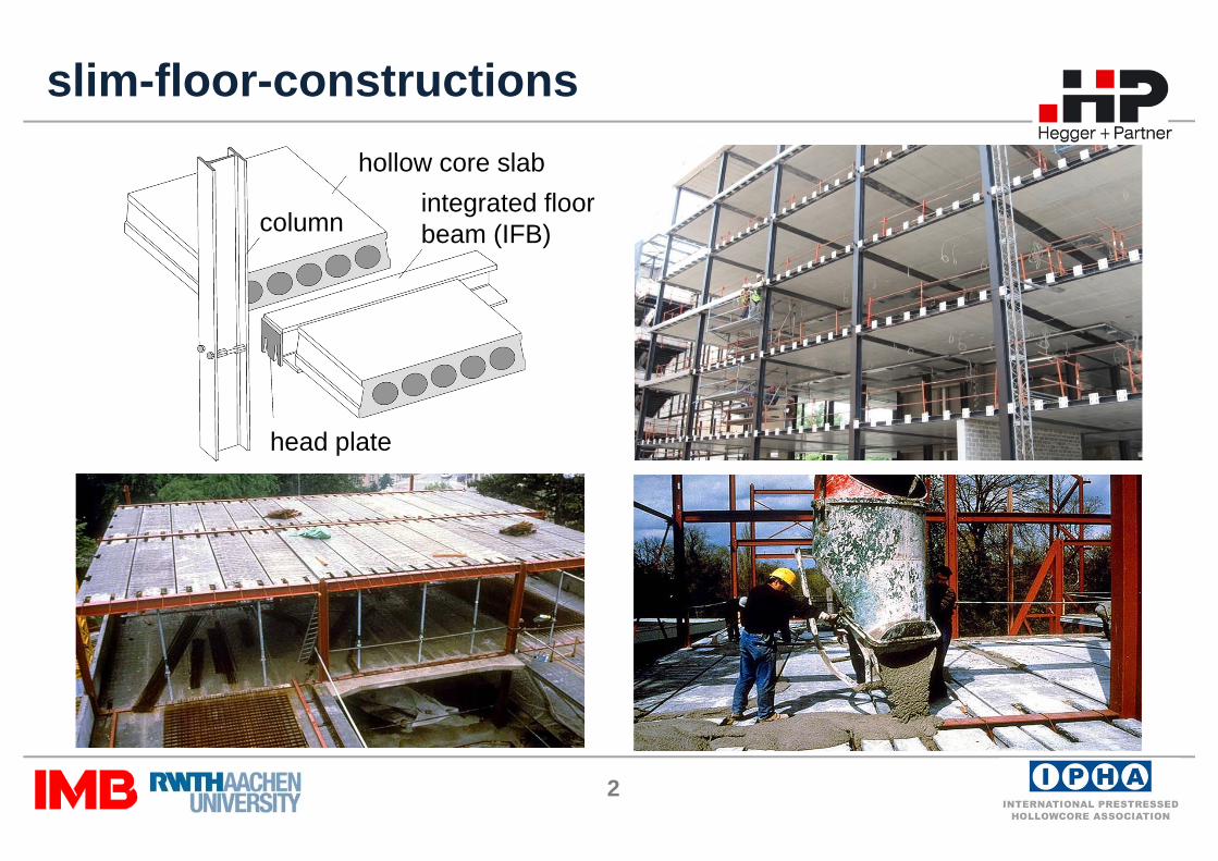
slim-floor-constructionshollow core slab
integrated floorbeam (IFB)
head plate
column

3
flexible supports
section 1-1
middle slab edge slab
transversebending
shear deformation andtransverse bending
4
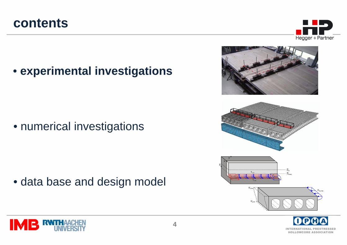
contents
• experimental investigations
• numerical investigations
• data base and design model
• experimental investigations
5
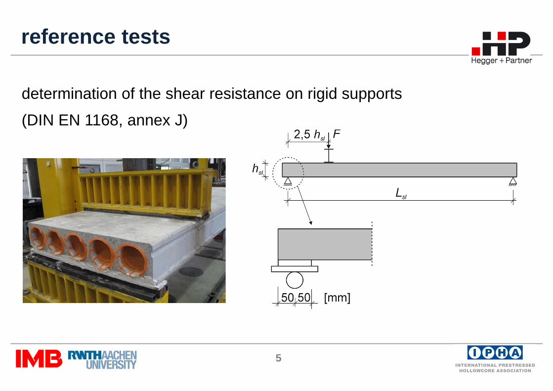
determination of the shear resistance on rigid supports
(DIN EN 1168, annex J)
reference tests

6
full-scale tests
edge slab
tie rods
ring beam
concrete grout
7
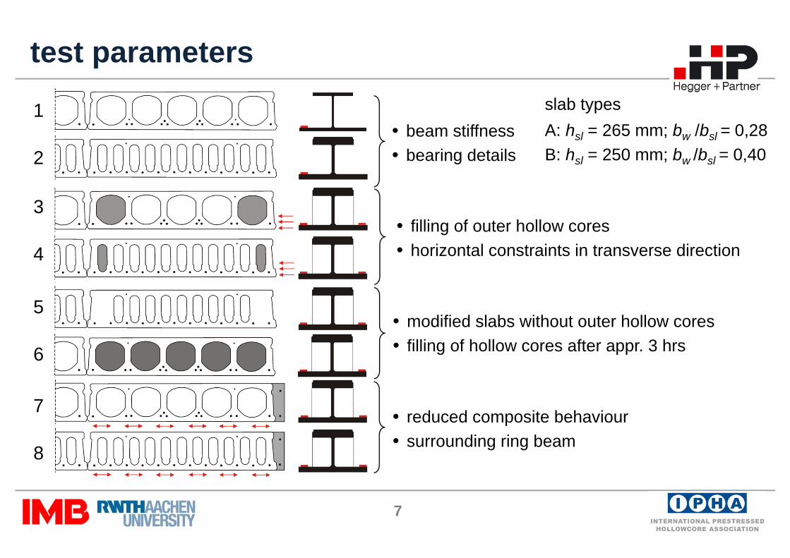
• reduced composite behaviour• surrounding ring beam
• modified slabs without outer hollow cores• filling of hollow cores after appr. 3 hrs
test parameters
• beam stiffness• bearing details
• filling of outer hollow cores• horizontal constraints in transverse direction
slab typesA: hsl = 265 mm; bw /bsl = 0,28B: hsl = 250 mm; bw /bsl = 0,40
1
2
3
4
5
6
7
8
8
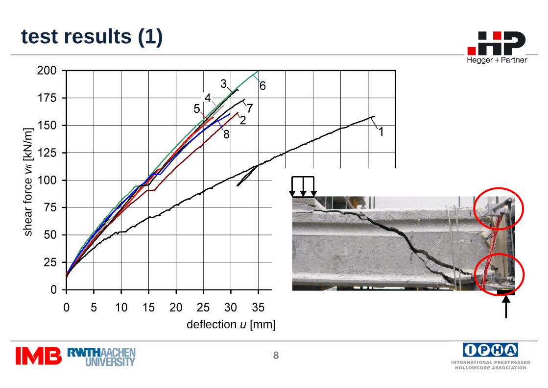
test results (1)sh
earf
orce
vfl[
kN/m
]
deflection u [mm]
9
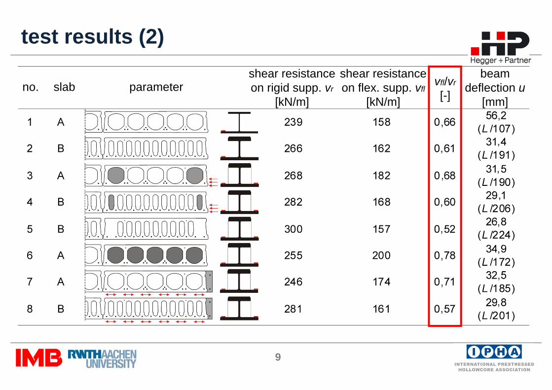
test results (2)
no. slab parametershear resistanceon rigid supp. vr
[kN/m]
shear resistanceon flex. supp. vfl
[kN/m]
vfl/vr
[-]
beam deflection u
[mm]

10
contents
• experimental investigations
• numerical investigations
• data base and design model

11
calibration of material parameters
reference tests
plane of symmetry
slab A
slab Bsh
earf
orce
vr[k
N/m
]
deflection u [mm]
tests slab Atests slab B
slab
slab
slab

12
full-scale tests
calibration of composite behaviour
shea
rfor
cevf
l[kN
/m]
deflection u [mm]
test 2
tests 3,4
load cyclesbeam
plane ofsymmetry
edge slablongitudinal joints
bearing surface
slab
slab
IFB
13
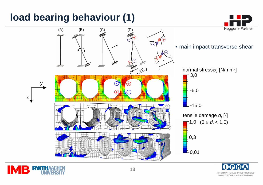
tensile damage dt [-]
normal stressσz [N/mm²]
-15,0
-6,0
3,0
0,01
0,3
1,0
load bearing behaviour (1)
+
+
-
-
y
z
(0 ≤ dt < 1,0)
• main impact transverse shear
14
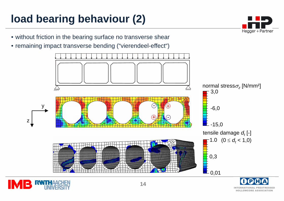
• without friction in the bearing surface no transverse shear• remaining impact transverse bending (“vierendeel-effect“)
load bearing behaviour (2)
tensile damage dt [-]
normal stressσz [N/mm²]
-15,0
-6,0
3,0
0,01
0,3
1.0
y
z
(0 ≤ dt < 1,0)
15
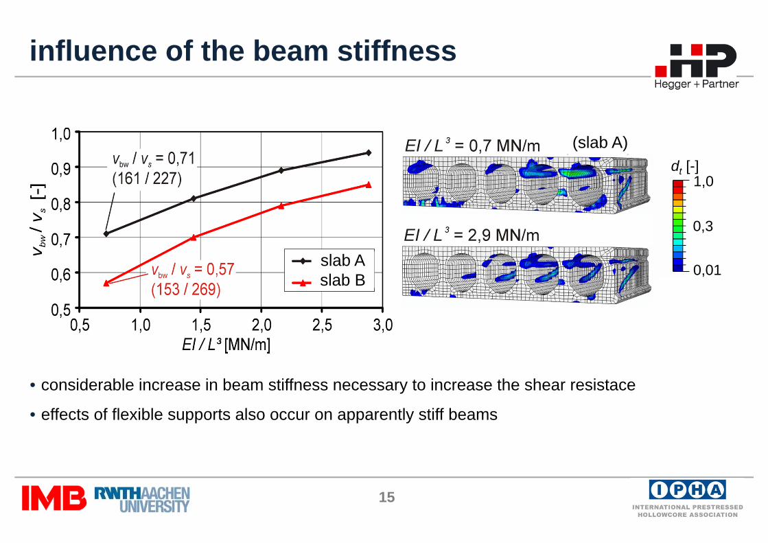
influence of the beam stiffness
dt [-]
0,01
0,3
1,0
• considerable increase in beam stiffness necessary to increase the shear resistace
• effects of flexible supports also occur on apparently stiff beams
vfl/
vr
slab Aslab B
(slab A)
16
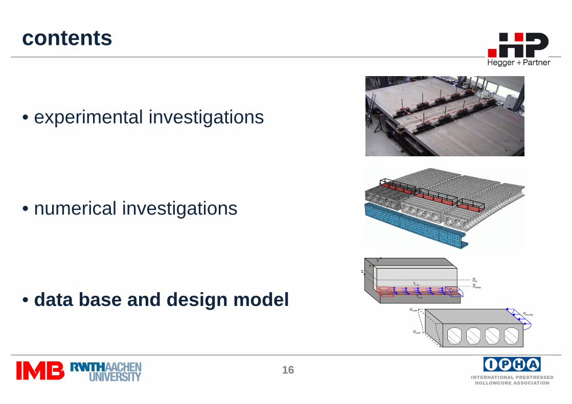
contents
• experimental investigations
• numerical investigations
• data base and design model
17
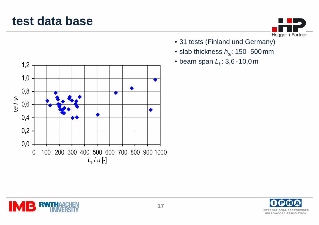
test data base• 31 tests (Finland und Germany)• slab thickness hsl: 150-500mm• beam span Lb: 3,6 -10,0m
vfl/
vr
18
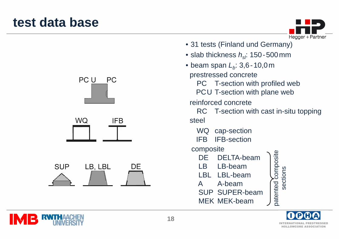
test data base• 31 tests (Finland und Germany)• slab thickness hsl: 150-500mm• beam span Lb: 3,6 -10,0m
prestressed concretePC T-section with profiled webPCU T-section with plane web
reinforced concreteRC T-section with cast in-situ topping
pate
nted
com
posi
te
sect
ions
vfl/
vr
steelWQ cap-sectionIFB IFB-section
compositeDE DELTA-beamLB LB-beamLBL LBL-beamA A-beamSUP SUPER-beamMEK MEK-beam
19
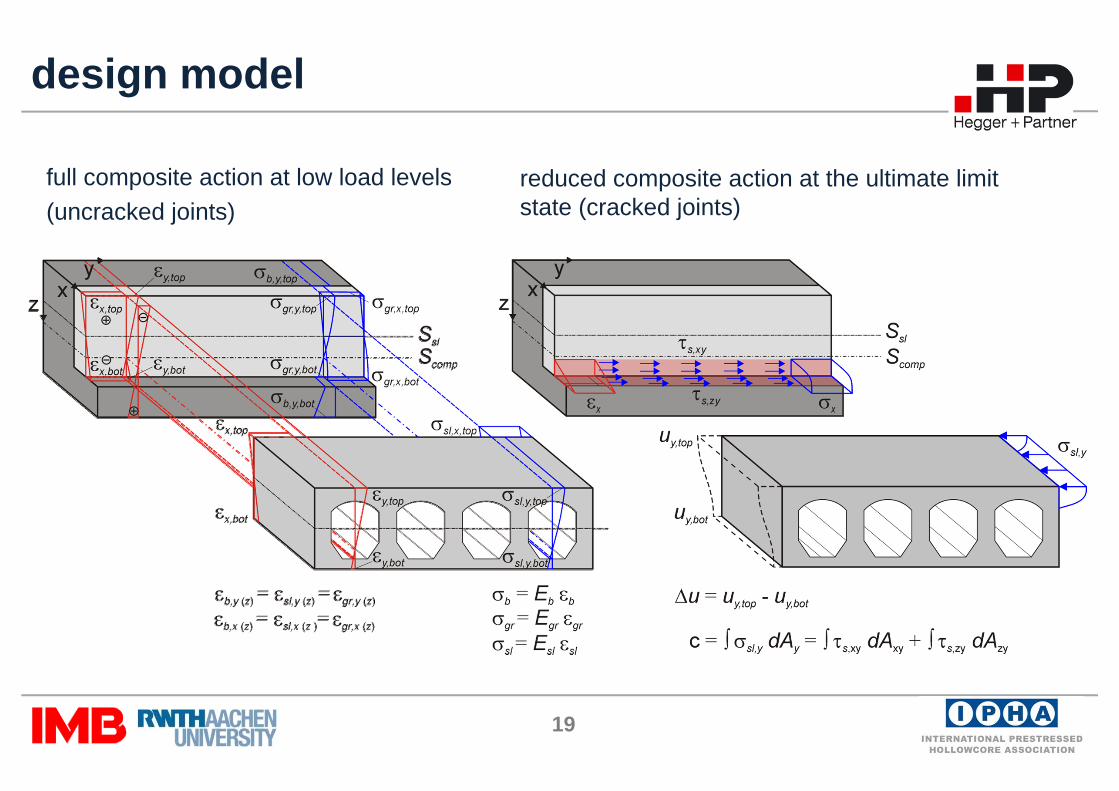
design model
full composite action at low load levels(uncracked joints)
reduced composite action at the ultimate limit state (cracked joints)
20
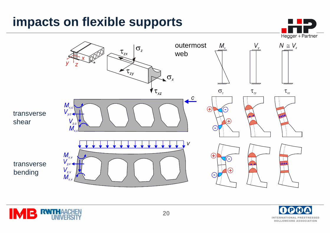
impacts on flexible supports
transverse shear
transversebending
outermostweb
21
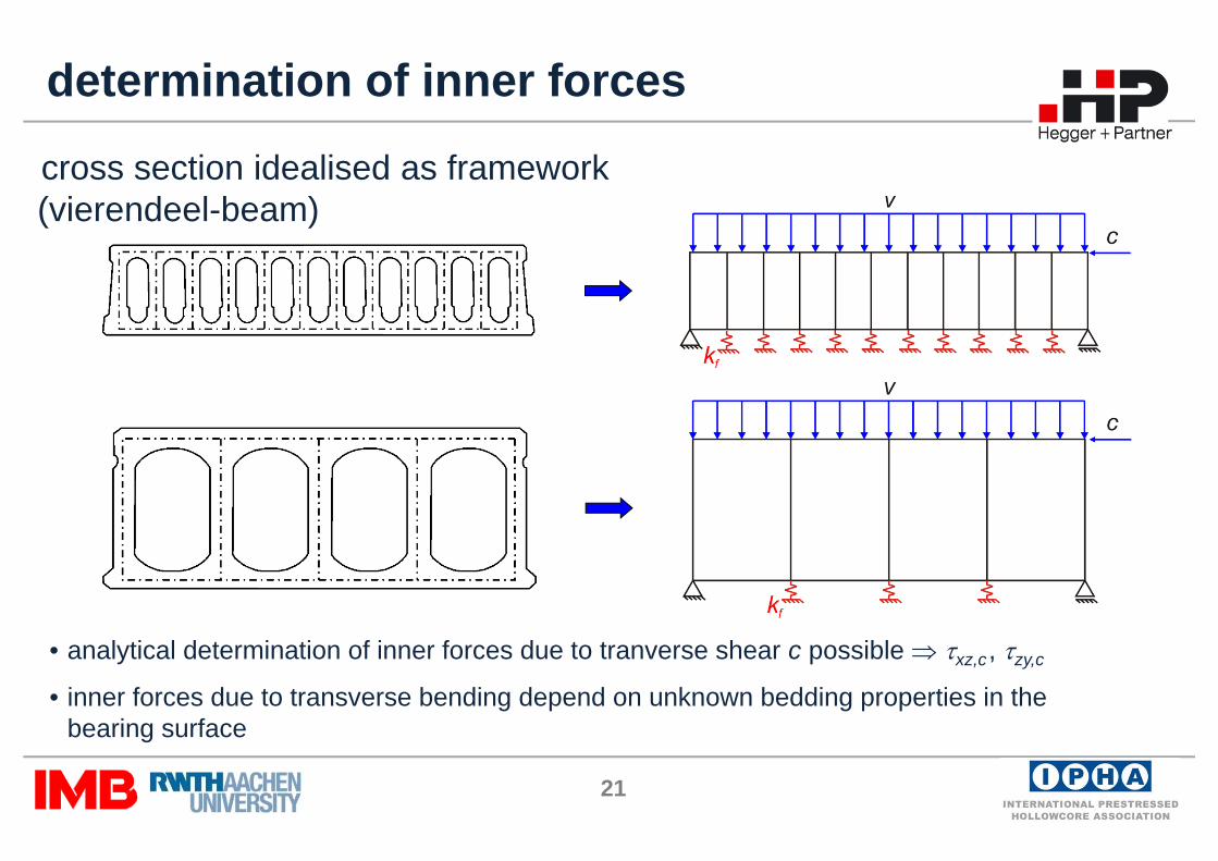
cross section idealised as framework (vierendeel-beam)
determination of inner forces
• analytical determination of inner forces due to tranverse shear c possible ⇒ τxz,c, τzy,c
• inner forces due to transverse bending depend on unknown bedding properties in thebearing surface

22
transverse bending
Platte A
Platte B
vfl/
vr
slabslabslabslab
slabslabslabslab
23
wsl
slcompc,xzfc,xz bI
SVmk μβτ =
sl
eff,slc,xz b
hk
21
=
xw
compc,zyfc,zy lb
Vmk μβτ23
=
)2(23
31
33
33
fl,sleff,slj,wsl
fl,sleff,slj,wslc,zy hhnbbn
hhnbbk
+
+=
3
31
sl
q,sl
b
bfv b
EIEILk β+=
⎟⎟⎟
⎠
⎞
⎜⎜⎜
⎝
⎛⋅−⎟⎟
⎠
⎞⎜⎜⎝
⎛−−⋅−
+⋅
= cppc,zyvct
xctxct
c,xzfcompsl
wslbw,R k
fff
mkSbIV a τατσσ
μβ
22 1
)1(
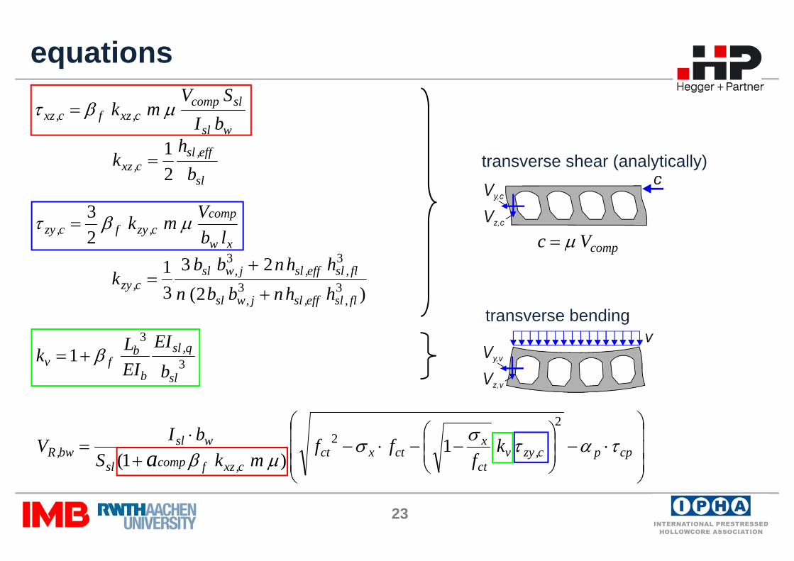
transverse shear (analytically)
transverse bending
equations
compVc μ=
24
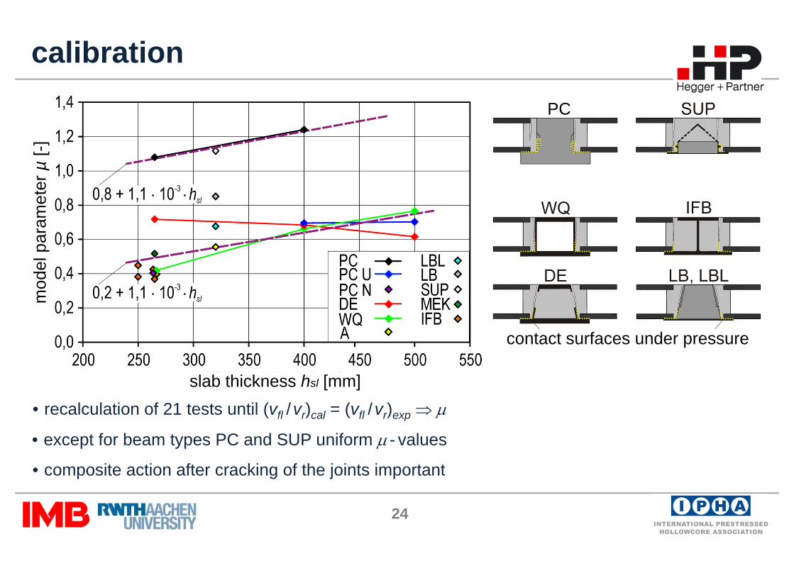
calibration
• recalculation of 21 tests until (vfl /vr)cal = (vfl /vr)exp ⇒ μ
• composite action after cracking of the joints important
• except for beam types PC and SUP uniform μ - values
PC
contact surfaces under pressure
slab thickness hsl [mm]
mod
el p
aram
eter
µ[-]

25
design example (1)slab 1
Loads
• self weight of slabs: g = 4.9 kN/m²• additionional dead load: Δg = 0.5 kN/m²• service load: q = 2.8 kN/m²
beam: HEA 400 section (fyk = 355 N/mm²)
Lsl = 12 mVRd,ct = 122.4 kN/m² (according constr. approval)
Lb = 6.2 mE = 210000 N/mm²I = 45070 cm4
=> vEd,slab = 12/2 x (1,35 x [4.9 + 0.5] + 1.5 x 2.8) = 68.9 kN/m
=> Med,beam = 2 x 68.9 x 6.2² / 8 = 662 kNm
σs = 662 / 45070 x 200 x 10² = 294 < 355/1.15 = 309 N/mm²
u = 5/384 x 2 x 12/2 x (4.9 + 0.5 + 2.8) x 6.2 4 / EI = 2 cm
(corresponding to ≈ L/300)
vRd,ct,fl = 70.6 kN/m (58 %)(≈ vEd)
26
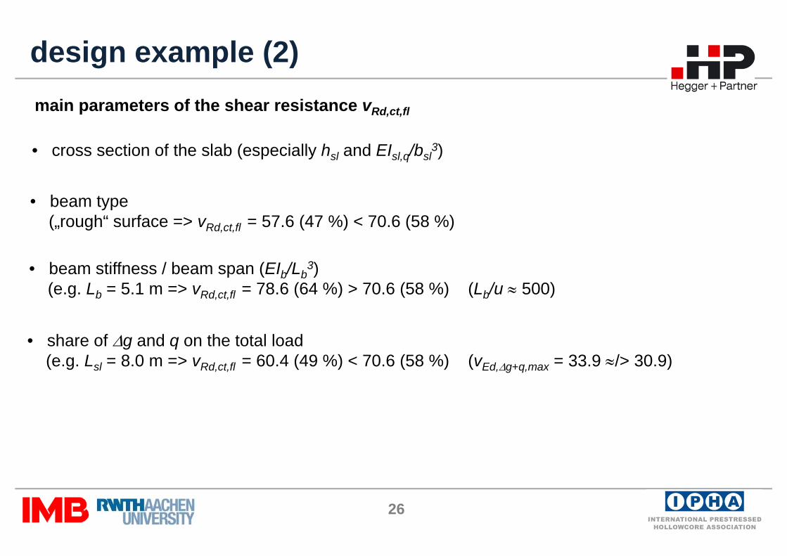
design example (2)main parameters of the shear resistance vRd,ct,fl
• cross section of the slab (especially hsl and EIsl,q/bsl3)
• share of Δg and q on the total load(e.g. Lsl = 8.0 m => vRd,ct,fl = 60.4 (49 %) < 70.6 (58 %) (vEd,Δg+q,max = 33.9 ≈/> 30.9)
• beam stiffness / beam span (EIb/Lb3)
(e.g. Lb = 5.1 m => vRd,ct,fl = 78.6 (64 %) > 70.6 (58 %) (Lb/u ≈ 500)
• beam type(„rough“ surface => vRd,ct,fl = 57.6 (47 %) < 70.6 (58 %)
27
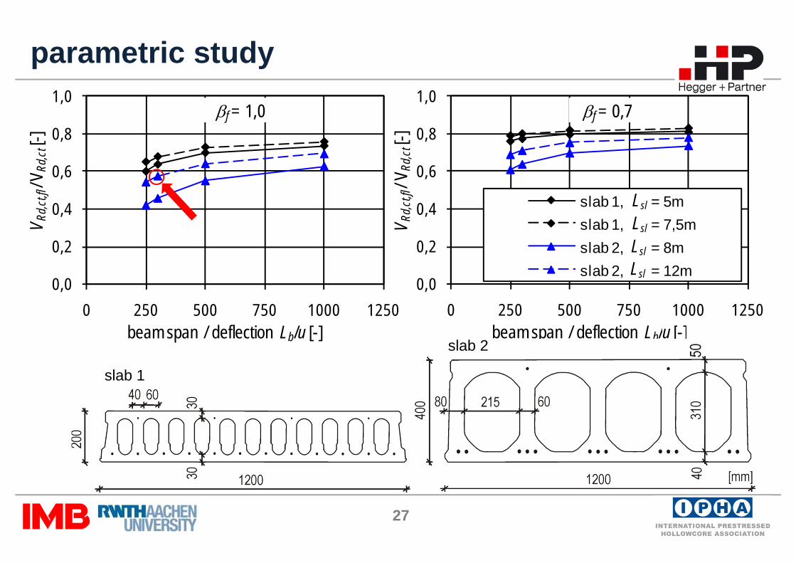
parametric study
slab 1
slab 2
0,0
0,2
0,4
0,6
0,8
1,0
0 250 500 750 1000 1250
V Rd,c
t,fl/V
Rd,ct
[-]
beam span / deflection Lb/u [-]
βf = 1,0
0,0
0,2
0,4
0,6
0,8
1,0
0 250 500 750 1000 1250
V Rd,c
t,fl/V
Rd,ct
[-]
beam span / deflection Lb/u [-]
slab 1, = 5mslab 1, = 7,5mslab 2, = 8mslab 2, = 12m
βf = 0,7
Lsl
Lsl
Lsl
Lsl
28
experimental investigations
• shear resistance ratios vfl /vr between 0,52 - 0,78 (shear tension failure)• shear resistance determined by shear deformations of the edge slabs• no clear influence of the beam deflection in the range from Lb /100 - Lb /200
summary
numerical investigations
• premature failure attributable to transverse shear and transverse bending• significant increase in beam stiffness necessary to enhance the shear resistance• effects of flexible supports also occur on apparently stiff beams
data base and design model
• 31 tests from Finland and Germany available • design model based on the load bearing at the ULS (cracked joints)• transverse shear considered analytically and transverse bending empirically