infrastructure development institute—japan · infrastructure development institute - japan...
TRANSCRIPT

New Raft Foundation Method (TNF Method) for Soft Ground 2
Conservation and maintenance technologies offered by Kawasaki Geological Engineering 4
C O N T E N T S
Infrastructure Development Institute – Japan (IDI) Suido-cho Bldg, 3-1, Suido-cho, Shinjuku-ku, Tokyo, 162-0811, JAPAN
Tel: +81-3-5227-4107 Fax: +81-3-5227-4109 E-Mail: [email protected] Website: http://www.idi.or.jp/english/00index.htm
✓ High stability
✓ Excellent durability
✓ Big porosity (56.5%) ✓ Low life cycle cost
RAKUNA-IV RAKUNA-IV
TNF Method for Soft Ground
IDIIDI QUARTERLYQUARTERLY
Japanese Infrastructure Newsletter
I n f r a s t r u c t u r e D e v e l o p m e n t I n s t i t u t e — J A P A N
September 2016 No.73

Infrastructure Development Institute - Japan
September 2016 No.73
2
New Raft Foundation Method (TNF Method) for Soft Ground
1.Background of Technical Development
In Japan or Asian countries, first-story or
second-story buildings are being built on
farmlands. Especially, several areas of river delta
regions are located in Southeast Asian countries.
There are soft ground and structurally weak, as
these are typically unsuitable for buildings on soft
ground. In these cases, raft foundation is
considered to be effective, but uneven settlement
and other damages become a problem. Therefore,
we propose TNF (Tender Net Foundation)
construction method. The proposed method is a
simplified ground improvement of raft foundation
with curb pattern structure of a combined unit of
the improved ground and foundation. The
combined unit is stable and can support to
building’s load. After that, it can restrain to
uneven settlement and lifting of the building.
2.Technical Characteristics of TNF Method
The TNF method is different from pile
foundation method or raft foundation method. As
mentioned above, it is a foundation system to
support the low structure on soft ground using
both the raft foundation and shallow soil
improvement mass constructed directly under the
raft foundation. The image of this method is
shown in Fig.1-1 and Fig.1-2. According to the Fig.
1-1, first improvement means improved ground as
curb pattern at the deep position. It includes
enclosure soil unimproved ground parts. The
second improvement layer is constructed as entire
surface improvement as a cover layer. And then,
excavation for foundation with preparation mold
of soil layer is included. The next step is
foundation steel frame, slab concrete, and finally
floor slab concrete is constructed.
1: First Improvement
2: Enclosure Soil Improved Ground
3: Second Improvement
4: Excavation of Foundation
5: Steel Frame Foundation and Slab Concrete
6: Floor Steel Frame and Slab Concrete
A complete image of first improvement is shown
in Fig. 1-2.
1 2
4 3
5
6
Fig. 1-1 Image of TNF Method
Infrastructure Development Institute - Japan
September 2016 No.73
3
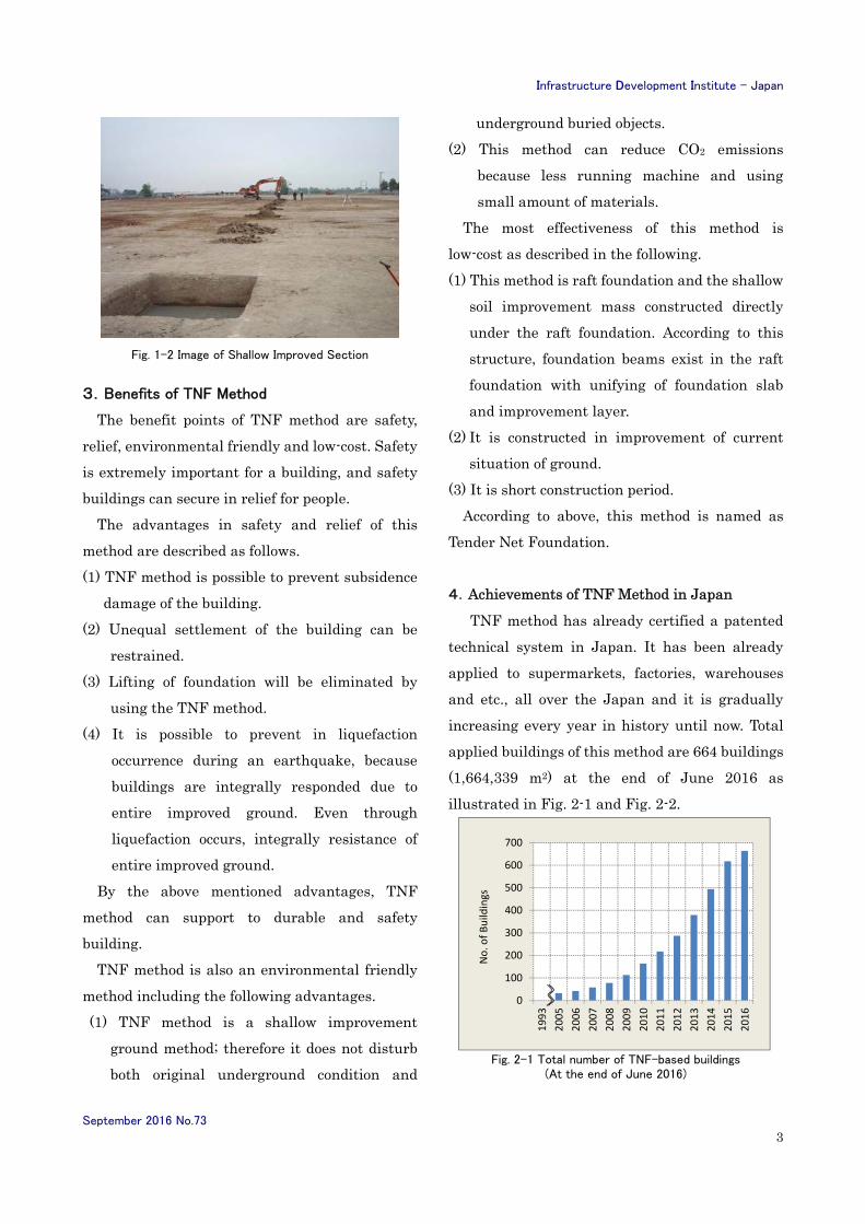
Fig. 1-2 Image of Shallow Improved Section
3.Benefits of TNF Method
The benefit points of TNF method are safety,
relief, environmental friendly and low-cost. Safety
is extremely important for a building, and safety
buildings can secure in relief for people.
The advantages in safety and relief of this
method are described as follows.
(1) TNF method is possible to prevent subsidence
damage of the building.
(2) Unequal settlement of the building can be
restrained.
(3) Lifting of foundation will be eliminated by
using the TNF method.
(4) It is possible to prevent in liquefaction
occurrence during an earthquake, because
buildings are integrally responded due to
entire improved ground. Even through
liquefaction occurs, integrally resistance of
entire improved ground.
By the above mentioned advantages, TNF
method can support to durable and safety
building.
TNF method is also an environmental friendly
method including the following advantages.
(1) TNF method is a shallow improvement
ground method; therefore it does not disturb
both original underground condition and
underground buried objects.
(2) This method can reduce CO2 emissions
because less running machine and using
small amount of materials.
The most effectiveness of this method is
low-cost as described in the following.
(1) This method is raft foundation and the shallow
soil improvement mass constructed directly
under the raft foundation. According to this
structure, foundation beams exist in the raft
foundation with unifying of foundation slab
and improvement layer.
(2) It is constructed in improvement of current
situation of ground.
(3) It is short construction period.
According to above, this method is named as
Tender Net Foundation.
4.Achievements of TNF Method in Japan
TNF method has already certified a patented
technical system in Japan. It has been already
applied to supermarkets, factories, warehouses
and etc., all over the Japan and it is gradually
increasing every year in history until now. Total
applied buildings of this method are 664 buildings
(1,664,339 m2) at the end of June 2016 as
illustrated in Fig. 2-1 and Fig. 2-2.
Fig. 2-1 Total number of TNF-based buildings
(At the end of June 2016)
0
100
200
300
400
500
600
700
1993
2005
2006
2007
2008
2009
2010
2011
2012
2013
2014
2015
2016
No. of Buildings

Infrastructure Development Institute - Japan
September 2016 No.73
4
Fig. 2-2 Build-up areas of TNF-based Buildings
(At the end of June 2016)
The TNF method is widely applied after
happening of the great east Japan earthquake in
2011 because almost TNF based buildings could
not be affected by the earthquake. TNF- based
building and conventional-based building
conditions are compared in the following figures.
According to our records, TNF-based building
didn’t occurred in unequally subsidence as
described in Fig. 3-1. On the other hand,
conventional-based building had wavy asphalt
according to Fig. 3-2.
Fig. 3-2 Conventional-based building
(Recorded Date: 17th March 2011)
Conservation and maintenance technologies offered by Kawasaki Geological Engineering
(Exploration, diagnosis and survey technologies for maintenance and management of roads, rivers,
harbors and other social infrastructure)
1.Conservation and maintenance technologies of
Kawasaki Geological Engineering
For more than 70 years since its inception in 1943,
Kawasaki Geological Engineering Co., Ltd
(“KGE”) has provided information on the ground
necessary for the construction and improvement
of social infrastructure to be built as a group of
specialists in the field of geological survey,
building on their expertise in boring survey,
geophysical exploration, and field measurement.
0.0E+00
5.0E+05
1.0E+06
1.5E+06
2.0E+06
1993
2005
2006
2007
2008
2009
2010
2011
2012
2013
2014
2015
2016
Bu
ilt-
up
Are
as [
m2 ]
Fig. 3-1 TNF-based Hardware Store
(Recorded Date: 17th March 2011)
Contact:
Technical Developer Information
Takeuchi Construction Inc.
President Kinji Takeuchi
E-mail : [email protected]
TEL : +81-848-60-1331
FAX : +81-848-62-6973

Infrastructure Development Institute - Japan
September 2016 No.73
5
Meanwhile, facing the rapid aging of the
infrastructure constructed for the high economic
growth period in JAPAN, KGE found a field in
which it could contribute as a geological
consultant, created a conservation division, and
has provided various technical services for
exploration, diagnosis, and survey required for
the maintenance of various infrastructure. This
introduction presents a look at the specialized
technologies in the field of conservation and
maintenance KGE has to offer.
2.Vehicle towed multi-chirp radar exploration
Recently, there has been increasing demand for
underground cavity investigation in order to
prevent accidents caused by depression in roads,
port facilities, river embankment, etc. In
particular, some of the lifelines beneath the road
surface are more than 40 years old since being
laid, present advanced deterioration, and are one
of the factors causing cavities. Since cavities are
an invisible problem in the soil, geophysical
exploration technologies capable of covering the
underground linearly and in broad areas are
required.
Among others, the ground penetrating radar
exploration technology with excellent cavity
detection ability and workability is applied in
many cases. However, the ground beneath roads
in Japan is mostly comprised of sand rich in
fine-grained fractions, contains a high ratio of
water, and hence attenuates radio wave
significantly.
This limits the maximum detection depth of
currently available ground penetrating radars to
only 1.5 m under the ground and makes it
impossible to detect all deteriorated life lines,
which are laid at various depths going down to 4
to 5m. Therefore, to explore aging deterioration of
the cavities, it has been necessary to carry out
exploration periodically and repeatedly.
This problem has led to an increase in survey cost
and collapses immediately after exploration,
affecting both investigation cost and users’ safety.
As one of the solutions, we have developed a
vehicle-towed multi chirp radar, a ground
penetrating radar for the exploration of deep
cavities, capable of surveying down to the depths
lifelines are buried.
[Characteristic of a Chirp-Radar]
A chirp radar is a radar that transmits
electromagnetic sine waves into underground and
compresses reflected signals into pulse waveforms.
The radar transmits signals changing the
frequency of sine waves according to desired
bandwidth (frequency range of signals
transmitted). In this case, the transmission
output depends on the transmission time. Further,
since the limit of resolution depends on the width
of transmission frequencies, the radar can
increase its transmission power without
impairing its resolution ability, which has been
difficult for conventional underground radars
using conventional pulse waves.
Fig-1 shows the results of the comparison
between a conventional radar and a chirp radar of
exploration targeting iron pipes buried at
different depths down to 3 m underground at 0.5
m intervals. While the conventional radar
detected the iron pipes down to 2.0 m
underground with semicircular waves, the chirp
radar clearly detected all of the iron pipes down to

Infrastructure Development Institute - Japan
September 2016 No.73
6
3 m underground.
[Vehicle-towed Multi-Chirp Radar]
A vehicle-towed multi-chirp radar is an
exploration device equipped with seven small
antennas using chirp signals and a large antenna
(Fig. 2). With transmission frequencies of 50 to
800 MHz, the seven small antennas are capable of
exploring down to about 3 m underground while
keeping high resolution equal to conventional
radars. On the other hand, though using
transmission frequencies of 50 to 300MHz and
hence with resolution inferior to the small
antennas, the large antenna is capable of
exploring the underground even deeper, down to 4
to 5m.
Towing the radar of a vehicle makes it possible to
scan underground at a speed of 40 to 50km/h. In
addition, the width of the radar being 2.5m (with
the antennas stretched out), the whole single lane
of the road can be scanned at a time.
Further, the radar features a drive camera that
films front and side outside scenes in sync with
the radar data and a VRS-GPS system capable of
high-accuracy position management of abnormal
points.
[Applications of vehicle-towed multi-chirp radars]
As shown in Fig. 3, vehicle-towed multi-chirp
radars made it possible to explore underground
cavities deeper than 1.5 m that has been difficult
for conventional radars. Hence, we think it is
possible to use these radars not only for the
exploration of shallow hollow cavities under
public roads, service roads along river
Fig. 2 Overview of the vehicle-towed multi-chirp radar
Fig. 1 Comparison of exploration ability between the
conventional radar and a chirp radar

Infrastructure Development Institute - Japan
September 2016 No.73
7
embankments, or under harbor quay aprons, but
also for the exploration of cavities or ground
structures at a variety of underground depths.
Hence, they will be very useful in detecting
cavities in their early development, estimating
their causes, and developing effective
maintenance plans.
3. Concrete diagnostic technology
The measurement of ultrasonic propagation
velocity on core holes, on obtained cores, or on
concrete surfaces, the measurement of intensity
of obtained core samples, including
small-diameter cores, and/or the improved on site
pull-off method are typical survey or diagnosing
methods to identify the depth of deterioration of
concrete structures. However, in addition to
having difficulty in quantitative evaluation, all of
the above methods still have limitations (such as
evaluation in the direction of depth in the
structure being only the average over several
centimeters) and have not yet been established as
a research and diagnostic techniques of
degradation depths. There has not been any
method for surveying and diagnosing concrete
structures capable of checking their physicality at
desired depths of structures and identify the
depth of deterioration.
That is an exact reason why we have developed
GoTEN (partial loading test in boreholes), a new
test method aimed at evaluating and diagnosing
the deterioration depth of concrete structures.
[Overview of GoTEN]
The test apparatus of GoTEN is comprised of a
cylindrical "body" of 40 mm in diameter and about
270 mm in length with a built-in displacement
meter and hydraulic piston, a hemispherical
“loading tip” of 6 mm in diameter to be inserted
into a core hole drilled in the structure, and a
“CCD camera" used to visually check the loading
point (attached as necessary) (Photo 1).
Photo-1 GoTEN
Fig. 3 Examples of cavities detected by chirp radars
Test device Semispherical loading tip of 6 mm in diameter CCD camera
attached as necessary
直径 40mm
長さ 270mm
Test device
Data collection deviceHydraulic pump
Infrastructure Development Institute - Japan
September 2016 No.73
8
The procedure of measurement is as follows:
(i) Drill a core hole of 42 mm or more in diameter;
(ii) Insert the test device into the core hole;
(iii) Fix the test device at the measurement depth;
(iv) Pressurize the test device with a hydraulic
pump and penetrate the loading tip into the hole
wall;
(v) Collect data on the load and amount of
penetration during the penetration into the hole
wall; and
(vi) Turn the test device to change directions of
measurement, and collect data on six or more
points at the same depth.
The amounts of penetration and load obtained by
measurement are expressed in a load-penetration
curve and the "penetration resistance" is
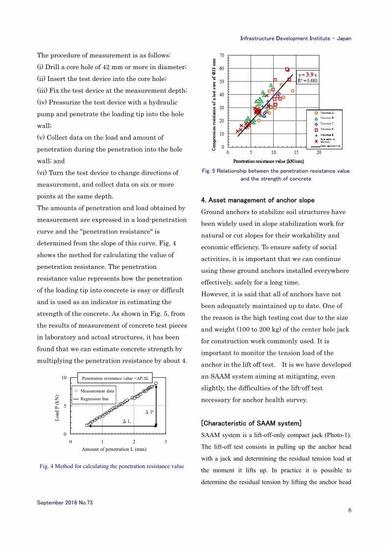
determined from the slope of this curve. Fig. 4
shows the method for calculating the value of
penetration resistance. The penetration
resistance value represents how the penetration
of the loading tip into concrete is easy or difficult
and is used as an indicator in estimating the
strength of the concrete. As shown in Fig. 5, from
the results of measurement of concrete test pieces
in laboratory and actual structures, it has been
found that we can estimate concrete strength by
multiplying the penetration resistance by about 4.
Fig. 4 Method for calculating the penetration resistance value
Fig. 5 Relationship between the penetration resistance value
and the strength of concrete
4. Asset management of anchor slope
Ground anchors to stabilize soil structures have
been widely used in slope stabilization work for
natural or cut slopes for their workability and
economic efficiency. To ensure safety of social
activities, it is important that we can continue
using these ground anchors installed everywhere
effectively, safely for a long time.
However, it is said that all of anchors have not
been adequately maintained up to date. One of
the reason is the high testing cost due to the size
and weight (100 to 200 kg) of the center hole jack
for construction work commonly used. It is
important to monitor the tension load of the
anchor in the lift off test. It is we have developed
an SAAM system aiming at mitigating, even
slightly, the difficulties of the lift-off test
necessary for anchor health survey.
[Characteristic of SAAM system]
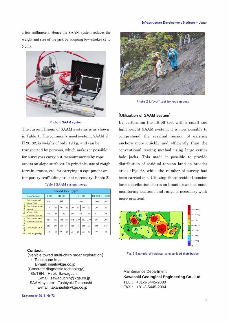
SAAM system is a lift-off-only compact jack (Photo-1).
The lift-off test consists in pulling up the anchor head
with a jack and determining the residual tension load at
the moment it lifts up. In practice it is possible to
determine the residual tension by lifting the anchor head
0
5
10
0 1 2 3
荷重
P (
kN)
貫入量 L (mm)
貫入抵抗値=ΔP/ΔL
測定データ
回帰線
ΔL
ΔP
Penetration resistance value =ΔP/ΔL
Measurement data
Regression line
Loa
d P
(kN
)
Amount of penetration L (mm)
Infrastructure Development Institute - Japan
September 2016 No.73
9
a few millimeters. Hence the SAAM system reduces the
weight and size of the jack by adopting low-strokes (2 to
5 cm).
Photo 1 SAAM system
The current lineup of SAAM systems is as shown
in Table-1. The commonly used system, SAAM-J
II 20-82, is weighs of only 19 kg, and can be
transported by persons, which makes it possible
for surveyors carry out measurements by rope
access on slope surfaces. In principle, use of rough
terrain cranes, etc. for carrying in equipment or
temporary scaffolding are not necessary (Photo 2).
Table 1 SAAM system line-up
Photo 2 Lift-off test by rope access
[Utilization of SAAM system]
By performing the lift-off test with a small and
light-weight SAAM system, it is now possible to
comprehend the residual tension of existing
anchors more quickly and efficiently than the
conventional testing method using large center
hole jacks. This made it possible to provide
distribution of residual tension land on broader
areas (Fig. 6), while the number of survey had
been carried out. Utilizing these residual tension
force distribution charts on broad areas has made
monitoring locations and range of necessary work
more practical.
Fig. 6 Example of residual tension load distribution
J I-300 J II-1500 J II-2000
Maximum pullforce (kN)
300 1500 2000
Maximum stroke(mm)
10 20 20 50 20 10 50 20 20 20
Center holediameter (mm)
62 43 59 102 67 75
Maximum outerdiameter (mm)
153 155 185 185 195 210 210 230 230 260
Jack length (mm)151 108 114 144 125 115 155 125 145 175
Jack weight (kg)14 15 19 23 25 25 32 30 40 63
Len
gths
& w
eigh
t
82 82
SAAM Jack Types
Specifications J II-600 J II-1000
600 1000
Perf
orm
ance
Contact: [Vehicle towed multi-chirp radar exploration] : Toshimune Imai E-mail: [email protected] [Concrete diagnostic technology]
GoTEN: Hiroki Sawaguchi, E-mail: [email protected] SAAM system: Toshiyuki Takanashi E-mail: [email protected]
Maintenance Department
Kawasaki Geological Engineering Co., Ltd
TEL: +81-3-5445-2080 FAX: +81-3-5445-2094

Infrastructure Development Institute - Japan
September 2016 No.73
10
About IDI and IDI-quarterly
Infrastructure Development Institute (IDI)-Japan is a general incorporated
association operating under the guidance of Ministry of Land, Infrastructure,
Transport and Tourism of Japanese Government.
IDI provides consulting services for mobilizing International Assistance to
developing countries, promoting international exchange of information and human
resources, and supporting globalization of project implementation systems targeting
both developed and developing countries in the field of infrastructure.
IDI has been publishing the free quarterly journal “IDI Quarterly” since1996 for the
purpose of introducing information relating to public works and construction
technologies developed in Japan to foreign countries. We have distributed the
journal to administration officials in more than 90 countries around the world by
e-mail.
We also appreciate it very much if you would provide new project information from
your country. If you have a manuscript, please send it to us by E-mail so we may
include it as an article in our journal IDI-Quarterly. Please refer to an example
article “Water Pipeline Projects” from Mongolia. (See IDI Quarterly No.52) and
“Manipulator Controlled Decontamination of Surfaces in Nuclear Power Plants”
(See IDI Quarterly No.61).
If you are interested, send manuscripts to us following the instructions below.
Instructions for contributors:
Texts must be written in English within 800 words.
MS-WORD.docx or text.txt files are acceptable.
Figures and photos should be supplied in an electric format.
All manuscripts will undergo some editorial modification.
The editor reserves the right not to publish manuscripts that are not
appropriate for this journal.
Manuscript fee will not be paid.
Please send manuscript files to “[email protected]” by e-mail.