infra-red flame detection - sos-safety.com · of two separate sensor elements. the time to alarm is...
TRANSCRIPT

123
FV282f+
INFRA-RED FLAME DETECTION
FLAMEDETECTOR
USER MANUAL
TRIPLE IR
FM APPROVED
fv282_front_iss2.fm Page 1 Monday, April 23, 2007 11:32 AM

PAGE
A) INTRODUCTION 1
1. Introduction 1
2. Flame Detection Operation 1
3. General Construction 4
B) PRODUCT APPLICATION 5
1. Application 5
2. Benefits of the FV282f+ 6
C) SYSTEM DESIGN INFORMATION 7
1. Introduction 7
2. Electrical Characteristics 7
3. Mechanical Characteristics 7
4. Environmental 9
5. Ordering Information 11
6. Operation 11
7. Performance Characteristics 15
8. Design of System 22
9. Approvals and Compliance with Standards 23
D) INSTALLATION 24
1. General 24
2. Mounting a Detector 24
3. Detector Wiring 26
E) COMMISSIONING 31
1. Connecting and Commissioning theDetectors 31
F) MAINTENANCE 36
1. General 36
FV282f+ USER MANUAL INDEX
fv282f+_TOC_iss2.fm Page 1 Monday, April 23, 2007 11:24 AM

SECTION A - INTRODUCTION
1
1. INTRODUCTION
The FV282f+ triple IR flame detectors is FM Approved flameproof (see Section 9).
The FV282f+ Advanced Flame Detector has approved Fault and Alarm Relay outputs. It also hasa 4-20mA Interface. The detector offers high performance flame detection capability andexcellent immunity to blackbody radiation.
2. FLAME DETECTION OPERATION
The FV282f+ detectors analyse radiant energy at three different wavelengths and, as such, offerthe full benefits of Triple IR flame detectors. The detector uses a well proven, flame detectiontechnique. This is based on monitoring for modulated infra-red radiation in the 4.3 μm wavebandcorresponding to CO2 emission. It incorporates patented techniques for improved rejection of solarenergy by use of two 4.3 μm filters and for Gaussian noise rejection by averaging the output signalof two separate sensor elements.
The time to alarm is field adjustable. Three different alarm delays of 3s, 6s and 12s are provided.
2.1 BLACKBODY REJECTION
The FV282f+ incorporates a novel optical filter(1) which enables a single electronic infra-redsensor to measure the radiated energy present in two separate wavebands placed on either side ofthe flame detection waveband, at 3.8 μm and 4.8 μm respectively (see Figure A-1). The signalobtained from this ‘guard’ channel is cross-correlated with the signal from the flame detectionchannel to provide an accurate prediction of the non-flame energy present in the flame detectionwaveband. This prediction is independent of the temperature of the radiation source, allowing theFV282f+ to provide blackbody rejection over a wide range of source temperatures.(1) Patented, see Section C10.
Figure A-1 shows the amount of energy given by a ‘hot’ object (blackbody) as viewed in theelectromagnetic spectrum. This curve has a peak which moves further to the left with highertemperature objects. The amount of energy seen between 3.8 μm and 4.8 μm can be approximatedto a linear function. Thus a measurement of the energy at these two wavelengths providesinformation to calculate with sufficient accuracy the level of blackbody radiation at theintermediate flame detection frequency of 4.3 μm. The energy due to the emission from hot carbondioxide given by a flame is superimposed on that from any blackbody in the detector field of viewwithout adding any significant emissions at 3.8 μm or 4.8 μm, thus enabling proper segregationbetween non-flame signals and flame signals. Because a large fire will possibly produce a largeamount of black smoke which will behave like a blackbody and may weaken the carbon dioxidepeak, signals greater than a pre-determined upper limit will be classed as a fire.
The use of an optical processing technique, as opposed to the use of two separate electronic sensorsfor the guard channel, improves the overall reliability of the detector by reducing the number ofcomponents and eliminating the need for complex calibration procedures during manufacture.
fv282f+_iss2.fm Page 1 Wednesday, April 25, 2007 10:08 AM

2
2.2 DETECTION RANGE
The FV282f+ can detect on axis a fully developed 1ft2 (0.09m2) n-heptane pan fire at 164ft (50m)on the 50m setting and the same fire at 82ft (25m) on the 25m setting. A 40ft (12m) setting is alsoavailable.
2.3 DETECTION OF FLAME IN THE PRESENCE OFBLACKBODY RADIATION
The ability of the detector to determine accurately the amount of non-flame radiation received atany one time by the flame detection channel allows a variable alarm threshold to be determined(see Figure A-2). This threshold is positioned so as to minimise the possibility of a false alarm dueto the presence of modulated blackbody sources of different temperature and intensity.
Fig. A-1 Radiation from Objects
fv282f+_iss2.fm Page 2 Wednesday, April 25, 2007 10:08 AM

3
2.4 DETECTOR CONDITION SIGNALLING
The FV282f+ incorporates two different colour light emitting diodes, red for Alarm and yellow forFault. By using different flashing rates for the yellow (Fault) LED, separate indication of detector(electronic) fault and ‘dirty’ window (optical integrity monitoring) is provided.
Fig. A-2 Signal Processing
fv282f+_iss2.fm Page 3 Wednesday, April 25, 2007 10:08 AM

4
3. GENERAL CONSTRUCTIONFigure A-3 shows a general view of a complete detector.
The detector is of robust construction to allow its use in harsh environments.
The detector comprises a two-part stainless steel enclosure. The front section of the enclosurecontains the encapsulated electro-optical assembly which is connected to the terminal board on therear section by a small cableform. A sapphire window is fitted in the front of the housing. Thewindow allows infra-red radiation to fall on the sensors, the LED alarm and fault indicators arevisible through the window.
The front section of the enclosure is attached to the rear section by four captive screws. A sealprovided between the front and rear sections ensures protection to NEMA 4 (IP66/IP67).
Two 1/2″ - 14NPT cable entries are provided on the bottom. All electrical connections are madeto three 4-way terminal blocks.
The detector may be fitted directly to a suitable surface or an optional adjustable mounting bracketmay be used.
A stainless steel guard (Figure A-3) is fitted to the detectors to protect the integrity of the window.
FV282f+
Serial No.
U maxmaxW
==
31.5V650mW
Ambient Limits -40 to +80 C
0 0
Patented
APPROVED
F M
DO NOT REMOVECOVERS WHILECIRCUITS ARE
LIVE
SEAL CONDUITWITHIN 18"
TORQUE COVER BOLTSTO 7 LB.FT (10 N.M)
MAXIMUM
XXXXX
For temperature code T5, maximum ambient 80°C. Environmental ratin
g IP66
/67
Hazardous Locations Rating (CI I, Div 1, Grp B,D,CI II, GrpE,F,
G, CI II
I)
Melbourn Road,Bishopstown,Cork Ireland
Fig. A-3 FV282f+ Detector - General View
GUARD
fv282f+_iss2.fm Page 4 Wednesday, April 25, 2007 10:08 AM

SECTION B - PRODUCT APPLICATION
5
1. APPLICATION1.1 GENERALThe detectors are intended for the protection of high-risk areas in which accidental fires are likelyto result in flaming combustion with the production of carbon dioxide. Typical materials in thistype of risk are:
a) Flammable liquids, including petroleum products, alcohol, and glycol etc.
b) Flammable gases including methane.
c) Paper, wood and packing materials.
d) Coal.
e) Plastics.
These substances ignite readily and burn rapidly, producing flame, often accompanied by largevolumes of dark smoke.
Note: The detectors are not designed to respond to flames emanating from fuels whichdo not contain carbon eg hydrogen, ammonia, metals, and should not be usedfor such risks without satisfactory fire testing.
The FV282f+, by virtue of its construction and rejection of spurious radiation, is suitable for useboth indoors or outdoors in a wide range of applications.
Note: The detectors should be mounted only to rigid surfaces when the field of view ofthe detector is covering a large area of blackbody radiation, as oscillation of thedetector could cause false alarms, eg, pole mounted detectors in a windylocation.
1.2 FEATURES
• A self-test facility is incorporated to test a number of characteristics, includingthe cleanliness of the window. The self-test may be initiated remotely.
• Switch selectable range settings.
• Switch selectable time to alarm settings.
• Operational range up to 178 ft (54m), fuel dependant.
• Remote control of range.
• Completely solar blind.
• Very low quiescent power consumption.
• High sensitivity to hydrocarbon fire in oily environments.
• Rugged stainless steel 316 housing and mounting bracket.
• Flexible mounting and angular adjustment.
• Ease of installation.
• Connection for remote LED.
• Selectable latching/non-latching alarm output.
• Selectable latching/non-latching fault output.
fv282f+_iss2.fm Page 5 Wednesday, April 25, 2007 10:08 AM

6
2. BENEFITS OF THE FV282f+
Infra-red flame detectors offer certain benefits over detectors working in the visible or ultra-violetregions of the spectrum. For example they are:
• Highly sensitive to flame thus increasing probability of early detection ofhydrocarbon fires.
• Not greatly affected by window contamination by dirt and oil deposits thusdecreasing maintenance frequency leading to operating cost reduction.
• Able to see flames through smoke, and able to see flames through high densitiesof solvent vapours thus increasing the probability of early detection ofhydrocarbon fires over other (ultra-violet) detectors in the same conditions.
The FV282f+ have all the above benefits and additionally are:
• Completely “solar-blind” in normal conditions thus eliminating false alarms dueto direct or indirect sunlight.
• Insensitive to electric arcs thus eliminating false alarms from welding operations.
• Insensitive to artificial light sources. See Section C (6.4) for more details onfalse alarm performance.
• Sealed to NEMA 4 (IP66/IP67), when suitable cable glands and sealant are used,ensuring long term reliability in harsh environments.
fv282f+_iss2.fm Page 6 Wednesday, April 25, 2007 10:08 AM

SECTION C - SYSTEM DESIGN INFORMATION
7
1. INTRODUCTIONThe electrical, mechanical, environmental characteristics and the performance of the FV282f+flame detector, must be taken into account when designing a system which uses thesedetectors. This information is given below, together with guidance on detector siting.
2. ELECTRICAL CHARACTERISTICSThe FV282f+ provides a relay interface for alarm and fault conditions.
2.1 TECHNICAL DATASupply Voltage: 16.8V to 31.5V. (Voltage at the detector).
Reset Time/Voltage: Supply must be reduced to less than 2V for greater than 0.5 seconds.
Stabilisation Time after reset /power up: 30 seconds.
Detector current consumption without 4 to 20 mA current sink resistor connected. Detector supply28V.
Quiescent Current: 11mA typical (Fault relay energized).
Alarm Current: 30mA typical (Fault and Alarm relay energized).
Fault Current: 0.4 to 1.1mA pulsing. (neither Fault or Alarm relay energized).
Fault relay: Normally closed, opens under fault conditions.
Alarm relay: Normally open, closes under alarm conditions.
Detector current consumption with 4 to 20 mA current sink resistor connected. Detector supply28V
Quiescent Current: 15mA typical (Fault relay energized).
Alarm Current: 50mA. typical (Fault and Alarm relay energized).
Fault Current: 2.3 to 3.5mA pulsing.
There are two 4-20mA output modes (see Table 1):
• Discrete - where the output switches from normal to alarm.
• Continuous - where the output changes with the input signal and the alarm andpre-alrm may be set in the PLC.
CONDITIONDISCRETE SIGNALLING
(mA)CONTINUOUS SIGNALLING
(mA)
Non Window Fault 1.5 0
Window Fault 1.5 2Normal 4.5 4
Alarm 17 5.7 to 17
Table 1:
fv282f+_iss2.fm Page 7 Wednesday, April 25, 2007 10:08 AM

8
Note:
1) The relay contacts are rated 2A at 30V d.c.
2) No remote LED option is available.
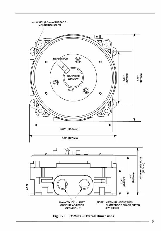
3. MECHANICAL CHARACTERISTICS3.1 TECHNICAL DATADimensions (see Figure B-1)
Weight: 8.4 lb (3.8kg)
Mounting Bracket Weight: 2.4 lb (1.1kg)
Materials
Enclosure: Stainless steel 316L.
Window: Sapphire.
Mounting Bracket: Stainless steel 316 S16.
Screws etc. exposed tothe elements: Bright stainless steel 316
Electronic Module Encapsulated
fv282f+_iss2.fm Page 8 Wednesday, April 25, 2007 10:08 AM
9
3.01
"(7
6.5m
m)
3.5"
max
*S
EE
NO
TE
(89.
5mm
)
3.94
"(1
00m
m)
6.57
"(1
67m
m)
5.87" (149.3mm)
6.57" (167mm)
4 x 0.315" (8.3mm) SURFACEMOUNTING HOLES
REFLECTOR
SAPPHIREWINDOW
20mm TO 1/2" - 14NPTCONDUIT ADAPTOR
OPENING x 2
LA
BE
L 2.06
"(5
2.5m
m)
NOTE: MAXIMUM HEIGHT WITHFLAMEPROOF GUARD FITTED3.7" (94mm)
Fig. C-1 FV282f+ - Overall Dimensions
fv282f+_iss2.fm Page 9 Wednesday, April 25, 2007 10:08 AM

10
4. ENVIRONMENTAL4.1 GENERAL
The design and construction of the FV282f+ detectors is such that it may be used over a wide rangeof environmental conditions. Relevant limits are given in Para 4.2.
4.2 TECHNICAL DATA
4.2.1 TEMPERATURE, HUMIDITY, PROTECTION AND PRESSURE
Operating temperature range: -40° to +80°C / -40°F to +176°F (110°C / 230°F
for short durations)Storage temperaturerange: -40°C to +80°C / -40°F to +176°FRelative humidity: up to 95% RH (non-condensing)Enclosure protection: NEMA 4 (IP66/IP67)*Normal operatingatmospheric pressure: 910mbar to 1055mbarHeat radiation fromsun or flame: 0 to 1000Wm2
Hazardous locationratings (Explosionproof): Class I, Division 1, Groups B, C and DHazardous locationratings (Dust ignitionproof): Class II, Groups E, F, G and Class III
* Cable gland entries must be suitably sealed to achieve the required NEMA rating.
50 ADJUSTMENT0
2.7" RAD
5.9" (149.3)
3.94"(100mm)
SURFACE MOUNTING DIMENSIONS
4 x MOUNTING HOLES
Fig. C-2 Adjustable Mounting Bracket and Surface Mounting Dimensions
fv282f+_iss2.fm Page 10 Wednesday, April 25, 2007 10:08 AM

11
4.2.2 DETECTOR PERFORMANCE
The FV282f+ detectors are designed and tested to Factory Mutual standards 3260 and 3615.
4.2.3 WEATHER SHIELD
A Stainless steel weather/sun shield is available to reduce the heating effect of the sun in tropicalconditions, where the detector has to be mounted in direct equatorial sun. The shield also providesprotection from rain and snow falling on the window. The sun shield fits round the bracket and isbolted on to the rear of the detector.
5. ORDERING INFORMATION
FV282f+ Relay Interface: 516.040.014
S100/S200 Mounting Bracket: 517.001.184
S200+ Weather/Sun Shield: 517.001.263
S200+ Spares Kit & Sealant: 517.001.266
T210+ Infra-red Test Source: 592.001.016
T210+ S200 Adaptor: 592.001.014T210+ Nicad battery and charger: 592.001.010Solo 100 telescopic extension pole set: 517.001.230Solo 101 extension pole: 517.001.226Solo 704 adaptor tube B: 517.001.224Solo 610 Carryall bag: 517.001.264
For information on the T210+, see Section E, Para 1.3.
6. OPERATION6.1 ALARM INDICATION
A red LED is visible through the front window, continuous illumination indicates an alarm.
6.2 ALARM SIGNALLINGThe detectors signal an alarm condition as follows:
• Alarm relay will close.
The FV282f+ may be set as alarm latching or non-latching. In the non-latching mode if the alarmsource is removed for greater than 5 seconds then the detector will stop indicating an alarm. In thelatching mode the controller must be reset to remove the alarm condition.
fv282f+_iss2.fm Page 11 Wednesday, April 25, 2007 10:08 AM

12
6.3 FAULT INDICATIONThe FV282f+ yellow LED will flash indicating a fault. Different flashing rates are used to indicatedifferent faults, as follows:
• Window obscuration: 0.5Hz
• Detector fault: 2.0Hz
6.4 FAULT SIGNALLINGThe detectors signal a fault condition as follows:
• Fault relay will open.
The FV282f+ detectors may be selected as fault latching or non-latching. In the non-latchingmode, the fault condition will be cancelled up to 80 seconds after the fault has been removed.
6.5 SENSITIVITY (RANGE) SELECTION
The range is switch selectable on a 6-way DIL switch (S1) on the backbox terminal PCB. Thefollowing nominal ranges are available:
• Extended range. 164 ft (50 meters)
• Normal range. 82 ft (25 meters)
There is provision for halving the range value selected by the switches. If the terminal connector‘Range’ is connected to 0V then the detection range is reduced to half that of the switchsetting. This may be done by taking cables to a remote contact the other side of which is connectedto the same 0V as the reference for ‘Line In’ supply.
6.6 DELAY TO ALARMThe minimum delay to alarm is 3 seconds from a fire being present in the field of view that is largeenough to be detected. This delay is also switch selectable using 6-way DIL switch (S1), thefollowing additional nominal values are available:
• 6 seconds.
• 12 seconds.
fv282f+_iss2.fm Page 12 Wednesday, April 25, 2007 10:08 AM
13
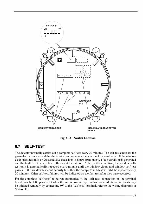
6.7 SELF-TEST
The detector normally carries out a complete self-test every 20 minutes. The self-test exercises thepyro-electric sensors and the electronics, and monitors the window for cleanliness. If the windowcleanliness test fails on 20 successive occasions (6 hours 40 minutes), a fault condition is generatedand the fault LED, where fitted, flashes at the rate of 0.5Hz. In this condition, the window self-test only is automatically repeated every minute until the window clears and window self-testpasses. If the window test continuously fails then the complete self-test will still be repeated every20 minutes. Other self-test failures will be indicated on the first test after they have occurred.
For the complete ‘self-tests’ to be run automatically, the ‘self-test’ connection on the terminalboard must be left open circuit when the unit is powered up. In this mode, additional self-tests maybe initiated remotely by connecting 0V to the ‘self-test’ terminal, refer to the wiring diagrams inSection D.
RELAYS AND CONNECTORBLOCK
INTERFACEPCB
SWITCH S1
ON
1
S1
CONNECTOR BLOCKS
Fig. C-3 Switch Location
fv282f+_iss2.fm Page 13 Wednesday, April 25, 2007 10:08 AM

14
The detector may be powered up in such a condition that the window ‘self-test’ can only beinitiated remotely on demand (the automatic window ‘self-test’ is disabled). In order for this to beachieved the detector must be powered up with the ‘self-test’ terminal connected to 0V (terminals3 or 5). To initiate the test for the first time after power up, the connection to the ‘self-test’ terminalmust be opened for at least 5 seconds and then closed again. This ‘self-test’ function (which takes10 seconds) will commence within 2 seconds of the closing and the result of the test indicated foras long as the connection remains closed.
If the test passes, an alarm condition will be indicated and if it fails a fault condition will beindicated. To remove the test indication, the connection to the ‘self-test’ terminal must beopened. A self-test fail indication due to a window fault will remain until a window ‘self-test’ issuccessful and will then unlatch after a 1 minute delay. The ‘self-test’ should not be repeated morefrequently than every 20 seconds (to allow the ‘self-test’ circuitry to recharge) as erroneous resultsmay occur.
Note that if a unit is poorly sited such that sunlight can reach the window test detector element, thereceive amplifier may saturate. In this event, that particular test is aborted and if this situationpersists for 6 hours 40 minutes, the unit will register a fault condition.
CAUTION:
A REMOTELY INITIATED TEST WILL PRODUCE AN ALARM SIGNAL FROM THE DETECTOR IF THE TEST SHOWS THAT THE WINDOW IS CLEAN.
TAKE THE NECESSARY STEPS TO INHIBIT A FULL ALARM CONDITION AT THE CONTROL PANEL BEFORE PROCEEDING.
IF THE SELF-TEST CONNECTION IS NOT OPENED AFTER A SELF-TEST THE DETECTOR WILL REMAIN DISABLED.
The window ‘self-test’ may be disabled by permanently connecting the ‘self-test’ terminal to 0V(pins 3 or 5) before power up. This may be desirable in those conditions in which contaminantsmay make the window appear dirty but which may not affect the ability of the detector to otherwisefunction normally.
The detector may be reset by reducing the voltage to less than 2 volts for greater than 0.5 seconds.
A remote LED may be used with the detector.
fv282f+_iss2.fm Page 14 Wednesday, April 25, 2007 10:08 AM

15
7. PERFORMANCE CHARACTERISTICS
7.1 GENERAL
A large number of fire tests have been carried during the development phase of the FV282f+detectors to determine their response limits. The results of these tests are summarised below. Inorder to appreciate their significance, an understanding of the mode of the operation of the detectoris necessary, and a brief explanation follows:
7.2 MODE OF OPERATION - BEHAVIOUR IN FIRE TESTS
Flaming fires involving carbonaceous materials produce large quantities of carbon dioxide. Thispart of the combustion process gives rise to a very high level of infra-red radiation in a narrowwavelength region centred upon 4.3μm.
The radiation from a fire flickers in a characteristic way and the detector uses this flicker signal inconjunction with the black body rejection technique described in Section A to discriminatebetween flame and non-flame signals.
The level of the signal depends upon the size of the flame and its distance from the detector. Forliquid fuels the signal level increases as the surface area of the burning liquid increases. For anytype of fire the signal level generally varies inversely with the square of the distance.
For convenience, fire tests are normally carried out using liquid fuels burning in pans of knownarea in still air.
Note: The results of fire tests can be significantly affected by weather conditionsprevailing at the time, eg - wind.
The sensitivity of a detector can then be conveniently expressed as the distance at which aparticular fire size can be detected. While the FV282f+ will reject modulated signals fromblackbody sources, the presence of such sources of high intensity may affect the sensitivity of thedetectors.
It is important to think in terms of distance rather than time because of the different burningcharacteristics of different fuels. Figure C-4 shows the response to two different fuels whichultimately produce the same signal level.
The signal level given by gasoline quickly reaches its maximum, and produces an alarm withinabout six seconds of ignition. Diesel, on the other hand, being less volatile, takes about a minuteto reach equilibrium and an alarm is given in about 60 seconds from ignition.
Note: If a fire test is carried out using non-miscible fuels then it is stronglyrecommended that water be placed in the bottom of the pan to keep it cool andprevent it deforming. A sufficient amount of fuel must be placed in the pan toensure combustion occurs over all of its area throughout the intended duration ofthe test.
fv282f+_iss2.fm Page 15 Wednesday, April 25, 2007 10:08 AM

16
The time taken by the fire to reach equilibrium depends of course on the initial temperature of thefuel. If kerosene were to be pre-heated to a temperature above its flash point then its behaviourwould be equivalent to that of gasoline at 25oC / 77oF.
The test data presented below refers to fires which have reached their equilibrium condition.
7.3 FIRE TEST DATA
7.3.1 N-HEPTANE
The most reliable fuel for consistent fire tests is n-heptane since it quickly reaches its equilibriumburning rate. FM detected 1ft2 (0.9m2) n-heptane pan fire on axis at 28.5m on 25m setting and54.4m on 50m setting.
7.3.2 OTHER LIQUID HYDROCARBONS
Typical ranges achieved with other fuels burning on 1ft2 (0.09m2) pans, relative to that for n-heptane, are as follows:
50m Range 25m RangeSetting Setting
Alcohol [Ethanol, Methanol] 66% 83%
Gasoline 63% 80%
Paraffin, Kerosene, JP4 54% 44%
Diesel fuel 50% 45%
The detection range is also a function of pan area. Manufacturers field trials indicate that thedetection range increases by approximately 20% when the pan area is doubled.
Fig. C-4 Characteristics of Fires
a) N-HEPTANE/GASOLINE FIRE 1 ft2 AT 85ft RANGE
b) DIESEL FIRE 1 ft2 AT 85ft RANGE
fv282f+_iss2.fm Page 16 Wednesday, April 25, 2007 10:08 AM

17
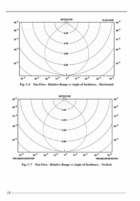
7.3.3 DIRECTIONAL SENSITIVITY
WARNING:WHEN MOUNTING THE FV282f+ DETECTORS, ENSURE THAT THE
PART OF THE FLAMEPROOF GUARD INDICATED IN FIG. C-5 IS NOT DIRECTED AT THE RISK AREA BEING PROTECTED.
The sensitivity of the FV282f+ is at a maximum on the detector axis. The variation of range withangle of incidence is shown in Figures. C-6 and C-7 for open air tests using 1 ft2 (0.09m2) kerosenepan fires with the detector operating at normal range.
FV282f+
Serial No.
U maxmaxW
==
31.5V650mW
Ambient Limits -40 to +80 C
0 0
Patented
APPROVED
F M
DO NOT REMOVECOVERS WHILECIRCUITS ARE
LIVE
SEAL CONDUITWITHIN 18"
TORQUE COVER BOLTSTO 7 LB.FT (10 N.M)
MAXIMUM
XXXXX
For temperature code T5, maximum ambient 80°C. Environmental ratin
g IP66
/67
Hazardous Locations Rating (CI I, Div 1, Grp B,D,CI II, GrpE,F,
G, CI II
I)
Melbourn Road,Bishopstown,Cork Ireland
Fig. C-5
DO NOT MOUNT THE THE FV282f+ DETECTOR WITH THIS PART OF THE GUARD DIRECTED AT THE RISK AREA BEING PROTECTED.
RESTRICTEDFIELD OF VIEWDUE TO WINDOWGUARD METALPROTRUSION
fv282f+_iss2.fm Page 17 Wednesday, April 25, 2007 10:08 AM
18
Fig. C-6 Pan Fires - Relative Range vs Angle of Incidence. - Horizontal
Fig. C-7 Pan Fires - Relative Range vs Angle of Incidence. - Vertical
fv282f+_iss2.fm Page 18 Wednesday, April 25, 2007 10:08 AM

19
7.4 HOT BODY DISCRIMINATION - FIELD OF VIEWThe FV282f+ flame detector discriminates against false alarms from hot radiating objects in thefield of view of the detector. This is done firstly by looking for modulation in the flame flickerfrequency band (1 to 20Hz) and secondly by comparing the signal in the guard channel. For theFV282f+ detector there are two areas in the field of view where the guard channel is partlyobscured. In these areas the discrimination against modulated black bodies is compromised and amodulated black body could possibly produce an alarm.
Fig. C-8 FV282f+ Detection Range for Viewing cones of 50, 60, 70, 80 and 90°.
fv282f+_iss2.fm Page 19 Wednesday, April 25, 2007 10:08 AM

20
The areas where this may happen are shown shaded in the field of view diagram in Fig. C-9. Detectors should be mounted so that potential hot bodies are not located in the shadedareas. This can normally be achieved by rotating the detector.
Fig. C-9 Areas Where FV282f+ May Not Discriminate BetweenFire and a Modulated Hot Body
fv282f+_iss2.fm Page 20 Wednesday, April 25, 2007 10:08 AM

21
7.5 FALSE ALARM DATA
The FV282f+ has been subjected to the following stimuli which might be considered potentialsources of false alarms. Unless otherwise specified, tests were performed at a minimum distancebetween source and detector of 1 ft (0.3m). Detectors were set to maximum sensitivity 164 ft (50mrange). Steady state sources were chopped at frequencies in the range 1 - 10Hz.
*Minolta Maxim/ Program Flash 5400HS - operated in both single and multi-flash modes.
RADIATION SOURCE IMMUNITY DISTANCE (ft)1 Sunlight No response
2 Sunlight with rain No response
3 100W tungsten filament lamp No response
4 Fluorescent lamp (bank of 4 x 32 W circular lamps) No response
5 125W mercury vapour lamp No response
6 1 kW radiant electric fire element > 1.5
7 2 kW fan heater No response
8 3 kW IR heater > 3
9 Halogen torch No response
10 Car headlights (60W halogen) No response
11 Lighted cigarette No response
12 Grinding metal No response
13 Electric arc welding (1/8” rod 120A) >16
14 Photographic quartz lamp (1000W) > 1
15 Photographic electronic flash unit* No response
fv282f+_iss2.fm Page 21 Wednesday, April 25, 2007 10:08 AM

22
8. DESIGN OF SYSTEM
8.1 GENERAL
Using the information given in Sections 5 and 6 it is possible to design a flame detection systemhaving a predictable performance. Guidelines on the application of the above data and on sitingof detectors is given in the following paragraphs.
CAUTION:
THE GUIDELINES GIVEN CANNOT CATER FOR ALL EVENTUALITIES THAT MAY BE ENCOUNTERED ON A SITE.
8.2 FIRE TEST DATA
It has been explained in Section 6 that the sensitivity of the detector is most easily specified interms of its response to well-defined test fires. Tests are conveniently carried out using a 1 ft2
(0.09m2) pan. Sensitivity to other pan areas is estimated from field trial results.
8.3 DETERMINING NUMBER OF DETECTORS
It will be clear that the number of detectors required for a particular risk will depend on the areainvolved and the fire size at which detection is required. Large areas or small fires require largenumbers of detectors.
There are as yet no agreed “rules” for the application of flame detectors and the overall systemsensitivity must therefore be agreed between the installer and the end user. Once this agreementhas been reached the system designer can determine the area covered by each detector using ascaled plot based on Figures. C-6 to C-7 and the fire test data. This plot is best drawn to the samescale as the site plan so that direct superposition can be used to determine detector coverage.
In carrying out the design, certain factors should be kept in mind:
a) For area rather than spot protection, the best coverage will normally be obtainedby mounting the detectors on the perimeter of the area and pointing into the area.
b) As the FV282f+ is a line of sight detector, any object within the detector’s fieldof view will cause a “shadow” in the protected area. Even small objects close tothe detector can cause large shadows.
c) The detector should not be mounted in such a position that water will collect onthe window.
d) The detectors are passive devices and will not react with one another. They maytherefore be positioned with their fields of view overlapping.
fv282f+_iss2.fm Page 22 Wednesday, April 25, 2007 10:08 AM
23
9. APPROVALS AND COMPLIANCE WITH STANDARDS
The FV282f+ detector (Fault and Alarm relay outputs) has been Approved by FactoryMutual. The detector is designed to comply with FM3615 (Explosionproof Electrical Equipment)in systems that comply with FM3260 (Flame Radiation Detectors for Automatic Fire AlarmSignalling). They are classified as explosionproof for Class I, Division 1, Groups B, C and D; anddust-ignitionproof for Class II, Groups E, F and G, Class III; and for indoor and outdoorapplication (IP66/67).
9.1 PATENTS
The FV282f+ design and manufacture is covered by the following patents:
UK patents GB 2 281 615, GB 2 335 489
European patent 0 064 811
US patent US 6,255,651
fv282f+_iss2.fm Page 23 Wednesday, April 25, 2007 10:08 AM
SECTION D - INSTALLATION
24
1. GENERAL
The FV282f+ detector may be surface mounted, or may use the S100/200 adjustable mountingbracket for fixing to a convenient rigid surface. All electrical connections are made via terminalblocks inside the detector rear housing. Two 1/2″ - 14NPT cable entries are provided. Guidance onmounting and wiring the detectors is given below.
2. MOUNTING A DETECTORThe location of each detector should have been determined at the system design stage accordingto the principles detailed in Section B and marked on the site plan.
The actual mounting position must, however, be decided during installation, and in choosing theposition the following principles together with the original system requirements should befollowed.
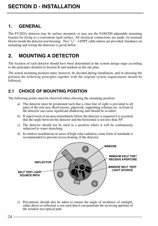
2.1 CHOICE OF MOUNTING POSITION
The following points must be observed when choosing the mounting position.
a) The detector must be positioned such that a clear line of sight is provided to allparts of the risk area. Roof trusses, pipework, supporting columns etc. in front ofthe detector can cause significant shadowing and should be avoided.
b) If supervision of an area immediately below the detector is required it is essentialthat the angle between the detector and the horizontal is not less than 50o.
c) The detector should not be sited in a position where it will be continuouslysubjected to water drenching.
d) In outdoor installations in areas of high solar radiation, some form of sunshade isrecommended to prevent excess heating of the detector.
e) Precautions should also be taken to ensure the angle of incidence of sunlight,either direct or reflected, is not such that it can penetrate the receiving aperture ofthe window test optical path.
fv282f+_iss2.fm Page 24 Wednesday, April 25, 2007 10:08 AM

25
f) The detector should not be sited in a position in which it will be subject to severeicing.
g) The detector must be mounted on a stable structure which is readily and safelyaccessible for maintenance staff.
h) Wherever possible, the detector should be mounted such that the face is tilteddownwards at a small angle to prevent water collection and lessen the settlementof particle deposits on the window.
The detector mounting bracket is to be secured with two 0.315 inch bolts at the mounting centresshown in Fig. D-1. A drilling template is provided to allow optimum selection of the mountingcentres of the 0.099 inch (2.5mm) diameter, 0.118 inch (3mm) deep pivot hole. The detector is tobe secured to the bracket using the four M8 screws supplied with the detector.
Alternatively, the detector may be secured directly to the fixing surface with four 0.315 inch bolts,studs or screws at the fixing centres shown in Figure D-1. The surface chosen for the mountingshould be flat over the area of the bracket to ensure a stable fixing.
The FV282f+ may be operated in any position but the mounting point must obviously be chosento allow sufficient clearance for adjustment of the angle and must also allow space for the cableassembly. A clearance of 8″ (200mm), in all directions, from the fixing point will normally besufficient to allow the full range of adjustment. (Figure D-2 refers).
50 ADJUSTMENT0
2.7" RAD
5.9" (149.3)
3.94"(100mm)
SURFACE MOUNTING DIMENSIONS
4 x MOUNTING HOLES
Fig. D-1 Adjustable Mounting Bracket and Surface Mounting Dimensions
fv282f+_iss2.fm Page 25 Wednesday, April 25, 2007 10:08 AM

26
3. DETECTOR WIRINGThe wiring between the detectors and control equipment must provide the required degree ofmechanical protection but allow the detector alignment to be adjusted to suit the area to beprotected.
In order to minimize the risk of radio frequency interference it is recommended that some form ofshielded wiring be used. The shield may take the form of steel conduit or metal sheathing of thecable and must be suitably grounded. Cabling must be terminated through 3600 at the detectorconduit entry and the detector housing must be solidly bonded to a good local ground.
The detector is supplied with two 20mm to 1/2” - NPT adaptors. The two 20mm conduit entrieswhen fitted with the 1/2" - 14 NPT provided permit convenient connection of the incoming andoutgoing lines with continuity of cable shields provided by internal connectors. The NPT adaptorsmust be used with either ‘o’ rings or sealant to comply with the IP rating.
It is recommended that, for optimum rejection of radio frequency interferences, ferrite beads areused to protect incoming and outgoing cables. See section 3.2 Fig. D-5 for fitting instructions.
On completion of installation, to ensure no moisture ingress to the detector during the timebetween installation and commissioning, fit the weatherproof cover Fig. D-3. Ensure that the ‘O’ring supplied is fitted to the cover. Securely tighten the four socket cap cover retaining screws.
Figs. D-4 and D5 show the wiring diagrams.
Fig. D-2 Clearance Required for Full Adjustment
fv282f+_iss2.fm Page 26 Wednesday, April 25, 2007 10:08 AM

27
3.1 CABLE ENTRY SEALING
CAUTION:CABLE GLANDS AND STOPPING PLUGS MUST BE SUITABLY SEALED TO
PREVENT THE INGRESS OF MOISTURE.
Only cable glands incorporating an inner cable seal should be used. In exposed outdoor areas it isrecommended that a shroud be fitted over the cable glands.
Cable glands should also be sealed to the detector housing by fitting a nylon washer between theirflange and the housing. The stopping plugs with a mushroom head and integral ‘O’ ring (supplied)must be used to plug unused conduit entries. The glands/stopping plugs should be hand-tightenedwith the addition of, at least, a further 1/4 turn applied by spanner or other suitable tool.
Alternatively, the thread of cable glands/stopping plugs used in Safe Area applications may besealed using PTFE tape or other jointing putty or mastic. Flameproof glands/stopping plugs maybe sealed using any non-setting grease or putty as described in IEC 79/14.
In applications where the ambient temperature is expected to be 104oF (40oC) or higher, cableglands with a silicon inner seal must be used and, when fitted, the shroud must be made of CRrubber.
CAUTION:TO COMPLY WITH FM FLAMEPROOF REQUIREMENTS, ALL ADAPTORS, GLANDS
AND STOPPING PLUGS MUST HAVE A MINIMUM OF 5 THREADS ENGAGED.
THE CONDUIT MUST BE SEALED WITHIN 18”
Fig. D-3 Protective Cover
fv282f+_iss2.fm Page 27 Wednesday, April 25, 2007 10:08 AM

28
CO
NT
RO
LE
QU
IPM
EN
T
FV
282f+
4L
INE
IN
30V50V
6L
INE
OU
T
8SC
NO
UT
12
SE
LF
TE
ST
10
SC
NIN9
N.C
12R
AN
GE
11
FV
282f+
4L
INE
IN
30V50V
6L
INE
OU
T
8SC
NO
UT
12
SE
LF
TE
ST
10
SC
NIN9
N.C
12R
AN
GE
11
+VE
-VE
FA
UL
TN
/C16
C15N
/O14 A
LA
RM
C13
FA
UL
TN
/C16
C15N
/O14 A
LA
RM
C13
74-20m
A
DO
NO
TU
SE
CO
NT
RO
LP
OIN
T
TOM
ON
ITOR
CIR
CU
ITTO
MO
NITO
RC
IRC
UIT
PO
SS
IBL
EM
ON
ITOR
ING
AR
RA
NG
EM
EN
T
C
N/C
C
N/O
EO
LM A
LA
RM
FAU
LTN
OT
E:
TH
EVA
LU
ES
OF
TH
EE
OL
AN
DM
ON
ITOR
ING
RE
SIS
TOR
(M)
AR
ED
EP
EN
DE
NT
ON
TH
ER
EQ
UIR
EM
EN
TS
OF
TH
EM
ON
ITOR
ING
EQ
UIP
ME
NT.
Fig. D-4 FV282f+ Relay Interface Wiring Diagram
fv282f+_iss2.fm Page 28 Wednesday, April 25, 2007 10:08 AM
29
FV
282f+
4L
INE
IN
30V50V
6L
INE
OU
T
8SC
NO
UT
12
74-20m
A
CO
NT
RO
LE
QU
IPM
EN
T
+24V
4-
20mA
0V
CO
NT
RO
LP
OIN
T
SE
LF
TE
ST
10
SC
N9N
.C12
RA
NG
E11
FA
UL
TN
/C16
C15N
/O14 A
LA
RM
C13
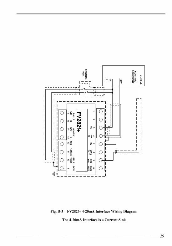
Fig. D-5 FV282f+ 4-20mA Interface Wiring Diagram
The 4-20mA Interface is a Current Sink
fv282f+_iss2.fm Page 29 Wednesday, April 25, 2007 10:08 AM

30
3.2 FITTING FERRITE BEADS
Fit the ferrite beads to conductors as shown in Fig. D-6. For optimum RF suppression, each pairof cables must be looped once around the ferrite bead.
Fig. D-6 Fitting of Ferrite Beads
fv282f+_iss2.fm Page 30 Wednesday, April 25, 2007 10:08 AM

SECTION E - COMMISSIONING
31
1. CONNECTING AND COMMISSIONING THE DETECTORS
When the system wiring has been successfully tested and the control equipment commissioned, thedetector electronic assemblies may be fitted. Set the Delay and (Table 2) Range/Latching,switches as required. Record the switch settings for future checking during service andmaintenance inspections. The Window self-test may be disabled by linking the self-test terminalto 0V before applying power to the unit (ie terminal 10 linked to either terminals 3 or 5). Self-testmay be demanded by taking the input high (disconnected) and then low again. Automaticoperation will not restart unless the self-test input is disconnected before power-up.
CAUTION:
DO NOT MOVE THE ALARM OR FAULT LATCHING SWITCHES AFTER THE DETECTOR HAS BEEN POWERED UP.
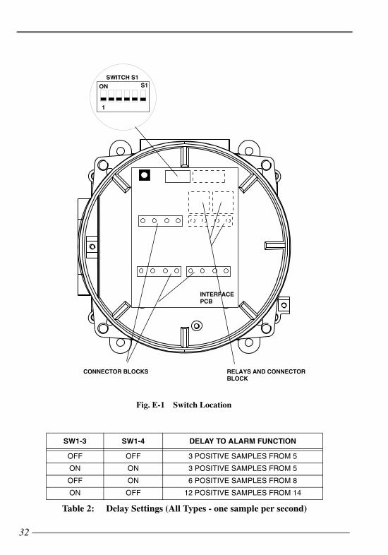
1.1 SWITCH SETTINGS
The following tables give the switch settings for switch S1, see Figure E-1 for switch location.
fv282f+_iss2.fm Page 31 Wednesday, April 25, 2007 10:08 AM
32
SW1-3 SW1-4 DELAY TO ALARM FUNCTION
OFF OFF 3 POSITIVE SAMPLES FROM 5
ON ON 3 POSITIVE SAMPLES FROM 5
OFF ON 6 POSITIVE SAMPLES FROM 8
ON OFF 12 POSITIVE SAMPLES FROM 14
Table 2: Delay Settings (All Types - one sample per second)
RELAYS AND CONNECTORBLOCK
INTERFACEPCB
SWITCH S1
ON
1
S1
CONNECTOR BLOCKS
Fig. E-1 Switch Location
fv282f+_iss2.fm Page 32 Wednesday, April 25, 2007 10:08 AM

33
* The Range Settings are halved if the Range Terminal (No 11) is connected to 0 volts.
# If switches SW1-2 and SW1-5 are changed from OFF to ON whilst the unit is powered, thechange will not be effective until the unit is powered down and re-started.
‡ In the Variable Signalling Current mode (SW1-6 ON), the alarm output will always beUNLATCHING, ie, the setting of SW1-5 has no effect. In this mode, the final alarm decision andlatching should be made at the controller, eg, PLC.
SW1-1OFF EXTENDED RANGE (50m)*
ON NORMAL RANGE (25m)*
SW1-2# OFF FAULT UNLATCHING
ON FAULT LATCHING
SW1-5# OFF ALARM LATCHING
ON ALARM UNLATCHING
SW1-6‡4-20mA only
OFF DISCRETE SIGNALLING CURRENTS
ON CONTINUOUS SIGNALLING CURRENTS
Table 3: Range and Latching Settings
fv282f+_iss2.fm Page 33 Wednesday, April 25, 2007 10:08 AM

34
LANYARD ATTACHED HERE
ATTACH HOOK HERE
Fig. E-2 Hanging Cord Connection
fv282f+_iss2.fm Page 34 Wednesday, April 25, 2007 10:08 AM
35
1.2 ASSEMBLING THE UNIT
Connect the hanging cord (as a precaution) to the top and bottom assemblies as shown in FigureE-2). Connect the two preformed cables from the top assembly to the bottom assembly (with thecables running to the centre of the detector). Fit the front assembly to the rear assembly. Careshould be taken to ensure that the internal wiring is not trapped between the terminal blocks andthe front assembly.
It should be noted that a rubber seal is provided between the front and rear sections of the housingand this seal must be clean and dry before assembly. It is also important to ensure that no moistureis trapped inside the housing. Torque the four socket cap retaining bolts to 7 lb.ft (10 N.m)maximum.
At this stage the angle of the detector should be adjusted to view the required area and the fixingnuts and bolts finally tightened. The cable from the circuit to the detector should then be routed,using cable ties or clips as necessary, to minimise the risk of physical damage.
1.3 TESTING
The detectors may be tested with a specially designed tester called the T210+. This is a unit thatis offered up to the front of the detector and produces a calibrated signal to check the detectorsensitivity. This may be set to 50m, 25m or 12m ranges.
The T210+ is not flameproof, but is Approved for use in hazardous areas. The rating is BASEEFAApproved EEx eib IIC T4 for use in Zone 1 and Zone 2 areas for group 2 gasses or lesser hazardsrated T1 - T4 as defined in EN 50014 : 1992 - Electrical Apparatus for Potentially ExplosiveAtmospheres - General Requirements.
fv282f+_iss2.fm Page 35 Wednesday, April 25, 2007 10:08 AM

SECTION F - MAINTENANCE
36
1. GENERAL The FV282f+ detector contains encapsulated electronic assemblies. There are no replaceable oradjustable components within the housing, which should not be opened once installed andcommissioned.
Routine maintenance is therefore limited to cleaning and testing the detectors.
1.1 ROUTINE INSPECTION
At regular intervals of not more than 3 months, detectors should be visually inspected to confirmthat no physical damage has occurred and that the alignment of the detectors has not beendisturbed. The detector windows should be checked to confirm that they are not blocked and thatno physical obstructions have been placed between the detector and the protected area. Check thatswitch settings are correct.
In addition, at intervals of not more than 1 year, each detector should be checked for correctoperation. Any excessive deposits of dirt, oil etc. should be removed from the detector housing asdescribed in 1.2.
Note: The inspection frequency specified above should be considered as a minimumrequirement to be applied in the average environment. The inspection frequencyshould be increased for dirtier environments or those which present a higher riskof physical damage.
For flameproof detectors, the following periodic checks should be made:
a) spigot joints should be separated and the faces examined for possible defects re-sulting from corrosion, erosion or other causes,
b) check that all stopping plugs and bolts are in position and tight,
c) no attempt should be made to replace or repair windows except by completeassembly replacement.
1.2 DETECTOR CLEANING
The FV282f+ detector is relatively tolerant of accumulations of dirt on the sensor window oroptical monitoring reflector (see Fig F-1). However, thick deposits of dirt and oil will cause a lossof sensitivity and a subsequent fault indication.
It is recommended that detectors be cleaned using water or a detergent solution. A stiff bristle (notwire) brush may be used to remove heavy deposits. Particular attention should be paid to thereflector and sapphire window (Figure F-1).
Note: The act of cleaning or polishing the detector face and window may cause adetector to produce an alarm, it is important, therefore that before the window iscleaned, the detector should be disarmed by isolating the relevant circuit at thecontrol unit. The circuit must be de-isolated as soon as cleaning is complete.
fv282f+_iss2.fm Page 36 Wednesday, April 25, 2007 10:08 AM

37
1.3 FAULT FINDING
If a fault is indicated at the controller it may be due to a number of self-test outputs, the mostcommon fault would be obscuration of the window.
If the remote self-test is connected, put the controller into the walk test mode, by switching the selftest input to 0V. If an alarm is indicated then the window is clean and the front-end circuitry isoperating correctly.
Reset the controller and wait two minutes. If no fault is indicated then it is likely that the fault wasdue to a software watchdog timeout which might be caused in rare circumstances by very excessiveelectrical interference.
If the detector fails the remote test or no remote test can be performed, clean the window and thereflector as specified, reset the controller. If the detector still shows a fault after a 71/2 period,replace the detector.
It should be remembered that unless the processor has malfunctioned the detector will still becapable of detecting a fire at higher levels or with greater susceptibility to false alarms unless thewindow is totally obscured by something other than gradual contamination.
A faulty detector will be indicated by a flashing built-in yellow LED.
REFLECTOR FACE WINDOW
Fig. F-1 Reflector and Window
fv282f+_iss2.fm Page 37 Wednesday, April 25, 2007 10:08 AM

NOTICE
All rights reserved. Reproduction of any part of this manual in anyform whatsoever without Thorn Security’s express written permissionis forbidden.
The contents of this manual are subject to change without notice.
All effort has been made to ensure the accuracy of this manual.However, should any errors be detected, Thorn Security would greatlyappreciate being informed of them.
The above not withstanding, Thorn Security can assume no responsibility for any errors in this manual or their consequences.
UM44 Issue 2
The right is reserved to modify or withdraw any product or service without notice.
120-415-862 Issue 2
Thorn Security LimitedDunham LaneLetchworth
HertfordshireSG6 1BE
Tel: +44 (0) 1462 667 700Fax: +44 (0) 1462 667 777
Scott Health & SafetyPO Box 569Monroe
North Carolina28111
Tel: 1-800-247-7257
fv282F+_back_iss2.fm Page 1 Monday, April 23, 2007 11:14 AM