information technology - object management group automated
TRANSCRIPT

ISO/IEC 19515:2019(E)Date: May 2019
Information technology - Object Management Group Automated Function Points (AFP), 1.0
formal/19-05-03
This version has been formally published by ISO as the 2019 addition standard: ISO/IEC 19515.


ISO/IEC 19515:2019(E)
Foreword
ISO (the International Organization for Standardization) and IEC (the International Electrotechnical Commission) form the specialized system for worldwide standardization. National bodies that are members of ISO or IEC participate in the development of International Standards through technical committees established by the respective organization to deal with particular fields of technical activity. ISO and IEC technical committees collaborate in fields of mutual interest. Other international organizations, governmental and non-governmental, in liaison with ISO and IEC, also take part in the work. In the field of information technology, ISO and IEC have established a joint technical committee, ISO/IEC JTC 1.
The procedures used to develop this document and those intended for its further maintenance are described in the ISO/IEC Directives, Part 1. In particular the different approval criteria needed for the different types of document should be noted. This document was drafted in accordance with the editorial rules of the ISO/IEC Directives, Part 2 (see www.iso.org/directives).
Attention is drawn to the possibility that some of the elements of this document may be the subject of patent rights. ISO and IEC shall not be held responsible for identifying any or all such patent rights. Details of any patent rights identified during the development of the document will be in the Introduction and/or on the ISO list of patent declarations received (see www.iso.org/patents).
Any trade name used in this document is information given for the convenience of users and does not constitute an endorsement.
For an explanation on the voluntary nature of standards, the meaning of ISO specific terms and expressions related to conformity assessment, as well as information about ISO's adherence to the World Trade Organization (WTO) principles in the Technical Barriers to Trade (TBT) see the following URL: www.iso.org/iso/foreword.html.
This document was prepared by the Object Management Group (OMG) and was adopted, under the PAS procedure, by Joint Technical Committee ISO/IEC JTC 1, Information technology, in parallel with its approval by national bodies of ISO and IEC.
This document is related to:
• ITU-T Recommendation X.902 (1995) | ISO/IEC 10746-2:1995, Information Technology - Open Distributed Processing - Reference Model: Foundations
• ITU-T Recommendation X.903 (1995) | ISO/IEC 10746-3:1995, Information Technology - Open Distributed Processing - Reference Model: Architecture
• ITU-T Recommendation X.920 (1997) | ISO/IEC 14750:1997, Information Technology - Open Distributed Processing - Interface Definition Language
Apart from this Foreword, the text of this document is identical with that for the OMG specification for Automated Function Points (AFP), v1.0.
ISO/IEC 2019 - All rights reserved i
ISO/IEC 19515:2019(E)
Introduction
The rapid growth of distributed processing has led to a need for a coordinating framework for this standardization and ITU-T Recommendations X.901-904 | ISO/IEC 10746, the Reference Model of Open Distributed Processing (RM-ODP) provides such a framework. It defines an architecture within which support of distribution, interoperability and portability can be integrated.
RM-ODP Part 2 (ISO/IEC 10746-2) defines the foundational concepts and modeling framework for describing distributed systems. The scopes and objectives of the RM-ODP Part 2 and the UML, while related, are not the same and, in a number of cases, the RM-ODP Part 2 and the UML specification use the same term for concepts which are related but not identical (e.g., interface). Nevertheless, a specification using the Part 2 modeling concepts can be expressed using UML with appropriate extensions (using stereotypes, tags, and constraints).
RM-ODP Part 3 (ISO/IEC 10746-3) specifies a generic architecture of open distributed systems, expressed using the foundational concepts and framework defined in Part 2. Given the relation between UML as a modeling language and Part 3 of the RM-ODP standard, it is easy to show that UML is suitable as a notation for the individual viewpoint specifications defined by the RM-ODP.
This International Standard defines a method for automating the counting of Function Points that is generally consistent with the Function Point Counting Practices Manual, Release 4.3.1 (IFPUG CPM) produced by the International Function Point Users Group (IFPUG). Guidelines in this specification may differ from those in the IFPUG CPM at points where subjective judgments have to be replaced by the rules needed for automation. The IFPUG CPM was selected as the anchor for this specification because it is the most widely used functional measurement specification with a large supporting infrastructure maintained by a professional organization.
ii ISO/IEC 2019 - All rights reserved

ISO/IEC 19515:2019(E)
Table of Contents
1 Scope ............................................................................................................... 1
1.1 Purpose ....................................................................................................................1
1.2 Applicability ..............................................................................................................1
1.3 Limitations ................................................................................................................1
2 Conformance and Compliance ......................................................................... 1
2.1 Conformance ............................................................................................................1
2.2 Compliance ..............................................................................................................2
2.3 Consistency with IFPUG CPM .................................................................................2
3 References ....................................................................................................... 3
3.1 Normative .................................................................................................................3
3.2 Non-normative ..........................................................................................................3
4 Terms and Definitions ....................................................................................... 3
5 Symbols (and abbreviated terms) ..................................................................... 6
6 Additional Information ....................................................................................... 6
6.1 Overview of Function Points .....................................................................................6
6.2 Function Point Usage Scenarios ..............................................................................7
6.3 Inputs to Automated Function Point Counting ..........................................................7
6.4 Outline of the Function Point Counting Process .......................................................8
6.5 The Application Model ............................................................................................106.5.1 The Application Model Elements ....................................................................................... 10
6.5.2 Detection of Data Functions ............................................................................................... 11
6.5.3 Detection of Transactional Functions ................................................................................. 15
6.5.4 Detection of Internal Versus External Logical Files ........................................................... 17
7 Determine Functional Size (Normative) .......................................................... 19
7.1 Entering Application Model Elements into Functional Sizing .................................197.1.1 Representation of the Application Model in KDM .............................................................. 19
7.1.2 Translating KDM Application Model Elements into SMM Inputs ........................................ 20
7.2 Determine Data Function Size ...............................................................................20
7.3 Determine Transactional Function Size .................................................................22
7.4 Determine Function Point Size ...............................................................................25
7.5 Output Generation ..................................................................................................25
ISO/IEC 2019 - All rights reserved iii

ISO/IEC 19515:2019(E)
7.6 Structured Metrics Meta-Model (SMM) Representation .........................................277.6.1 Computing Automated Function Point Size ....................................................................... 27
7.6.2 Computing External Output Size ........................................................................................ 27
7.6.3 Computing External Input Size ........................................................................................... 29
7.6.4 Computing Internal Logical File Size and External Interface File Size ............................... 30
8 References ..................................................................................................... 33
iv ISO/IEC 2019 - All rights reserved

INTERNATIONAL STANDARD ISO/IEC 19515:2019(E)
Information technology - Object Management Group Automated Function Points (AFP 1.0)
1 Scope
1.1 Purpose
This International Standard defines a method for automating the counting of Function Points that is generally consistent with the Function Point Counting Practices Manual, Release 4.3.1 (IFPUG CPM) produced by the International Function Point Users Group (IFPUG). Guidelines in this International Standard may differ from those in the IFPUG CPM at points where subjective judgments have to be replaced by the rules needed for automation. The IFPUG CPM was selected as the anchor for this International Standard because it is the most widely used functional measurement specification with a large supporting infrastructure maintained by a professional organization.
1.2 Applicability
This International Standard is applicable to the functional sizing of transaction-oriented software applications, and in particular those with data persistency. To be consistent with the IFPUG CPM, the International Standard provides details on the support of applications using relational databases. However, the International Standard can be used and extended for any type of transactional application with data persistency.
1.3 Limitations
This International Standard does not address the sizing of enhancements to an application or maintained functionality (often called Enhancement Function Points). Extensions of the automated counting methods described in this International Standard such as Automated Enhancement Function Points will be addressed in future addendums to this International Standard. This International Standard does not address sizing for the non-functional components of a software application. Non-functional components (as defined by IFPUG) include:
• Structural Quality Constraints Reliability, Security, Performance Efficiency, Maintainability, etc.
• Organizational Constraints locations for operations, target hardware, compliance to standards, etc.
• Environmental Constraints interoperability, security, privacy, safety, etc.
• Implementation Constraints development language, delivery schedule, etc.
2 Conformance and Compliance
2.1 Conformance
This International Standard is derived from IFPUG’s Function Point Counting Practices Manual, Release 4.3.1 (IFPUG CPM). However, explicit counting rules were specified in this International Standard in order to provide for rigorous automation that may not be in strict conformance with guidance in IFPUG’s manual. Therefore, there is no claim of strict
ISO/IEC 2019 - All rights reserved 1

ISO/IEC 19515:2019(E)
conformance with the IFPUG CPM standard. Additionally, this International Standard has made every attempt to conform to the extent possible with international standards for functional measurement, in particular ISO/IEC 25010, ISO/IEC 20926:2009, and NEN-ISO/IEC 24570. This International Standard conforms to OMG’s Knowledge Discovery Meta-model (KDM) and Structured Metrics Meta-model (SMM) in its specification and representation of the Automated Function Point counting and scoring process.
Conformance with this International Standard by Automated Function Point counting tools is determined by analyzing the KDM elements that constitute the Application Model and produce the final Automated Function Point count using the counting process specified in the SMM model presented in this International Standard. Output from this automated process should conform to the list of output artifacts listed in Clause 7.
2.2 Compliance
Implementations of this International Standard should be able to demonstrate the following attributes in order to claim compliance:
• Automated - Although the initial inputs such as the source code, definition of application boundary, and some naming conventions are provided manually to initiate Automated Function Point counting, the analysis of the source code and the actual counting must be fully automated.
• Consistent - Two independent and separate functional sizings performed on the same application source code using the same boundaries and other required manual inputs by different Automated Function Point tools that conform to this International Standard must produce the same results in terms of Automated Function Point size (i.e., the same number of Automated Function Points).
• Verifiable - Implementations that comply with this International Standard must clearly list each and every input the implementation requires and list each and every output that the implementation generates so that they can be audited by a third party. Implementations should provide a list of assumptions/heuristics (to the extent that this does not disclose proprietary information) used to transform the inputs to the outputs so that the calculations can be independently verified by third parties.
2.3 Consistency with IFPUG CPM
This International Standard for Automated Function Points follows the steps for the counting process in the IFPUG CPM to the extent possible for an automated system. An automated system relies on receiving the correct and complete list of inputs to fulfill this step. Consequently the initial step in the Automated Function Point counting process is the manual gathering of inputs and configuring them properly for analysis by the Automated Function Point counting technology. The remainder of the analysis and counting process is automated.
This International Standard prioritizes repeatability and consistency over consistency with the IFPUG CPM counting guidelines. In some counting situations, IFPUG guidelines are vague, leaving the interpretation to the judgment of the counter. Consequently, IFPUG certified Function Point counters often differ by as much as 10% or more in the counts they produce. In order to remove subjectivity, this International Standard makes explicit decisions about counting techniques in situations where the IFPUG guidelines were vague. Consequently we have introduced some variation from the IFPUG guidelines in order to achieve the precision required for automation and repeatability.
Automated Function Point counts may differ from the manual counts produced by IFPUG Certified Function Point counters. In fact, manual counts produced by different IFPUG Certified Function Point counters on the same code base will typically differ because of different interpretations of the designer’s or developer’s intent in creating various functional elements of an application. In the manual IFPUG counting process, documentation, and expert knowledge are typically used in sizing an application. These types of inputs are not available to an automated system. Hence, any
2 ISO/IEC 2019 - All rights reserved

ISO/IEC 19515:2019(E)
automated approach will be unable to capture information about the designer’s or developer’s intent that isn’t explicitly encoded in the application’s source code. Since this International Standard relies exclusively on the application’s source code as defined by its boundaries, it cannot capture any of the designer’s intentions that do not leave an ‘imprint’ on the source code. Some of these intentions might make a difference in manual counting. For this additional reason, the Automated Function Point counts produced by technology that is compliant with this International Standard may differ from manual counts produced by IFPUG Certified Function Point counters. The advantage of Automated Function Points is that a tool will produce repeatable, consistent counts, attributes that are not characteristic of manual counting.
3 References
3.1 Normative
The following normative documents contain provisions which, through reference in this text, constitute provisions of this Automated Function Point International Standard. For dated references, subsequent amendments to, or revisions of, any of these publications do not apply.
• Structured Metrics Meta-model, version 1.0 (SMM), formal/2012-01-05
• Knowledge Discovery Meta-model, version 1.3 (KDM), formal/2011-08-04
• Unified Modeling Language, version 2.4.1 (UML), formal/2011-08-05
• MOF/XMI Mapping, version 2.4.1 (XMI), formal/2011-08-09
3.2 Non-normative
• Function Point Counting Practices Manual, Release 4.3.1. ISBN 978-0-9753783-4-2
• Function Point Analysis. ISBN 0-201-69944-3.
4 Terms and DefinitionsFor the purposes of this International Standard, the following terms and definitions apply.
Application Modelabstract source code representation of an application that results from analysis of the source code. It contains the minimum information required to measure Automated Function Points, that is, the static elements of an application defined by associated KDM elements that are used in the Automated Function Point counting process.
Boundarythe boundary is a conceptual interface between the software and the users. (IFPUG CPM)
Complete transactionin the context of this International Standard, a transaction is considered as complete whenever the static code analyzer can find one or several code paths starting from the user interface and continuing down to the data entities.
ISO/IEC 2019 - All rights reserved 3

ISO/IEC 19515:2019(E)
Data Element Type (DET)a data element type is a unique user recognizable, non-repeated attribute that is part of an ILF, EIF, EI, or EO. (ISO/IEC 20926:2009)
Data Functionfunctionality provided to the user to meet internal or external data storage requirements. A data function is either an ILF or EIF). (ISO/IEC 20926:2009)
Database TableSQL data table or KDM’s data:RelationalTable.
External Inquiry (EQ)a form of data that is leaving the system. However, since automated counting tools cannot distinguish between External Inquiries and External Outputs, all External Inquiries will be included in and counted as External Outputs. (ISO/IEC 20926:2009)
External Input (EI)elementary process that processes data or control information sent from outside the boundary (ISO). (ISO/IEC 20926:2009)
External Interface File (EIF)]a user recognizable group of logically related data or control information, which is referenced by the application being measured, but which is maintained within the boundary of another application. (ISO/IEC 20926:2009)
External Output (EO)an elementary process that sends data or control information outside the boundary and includes additional processing logic beyond that of an External Inquiry. (ISO/IEC 20926:2009)
File Type Referenced (FTR)data function (IFL or EIF) read and/or maintained by a transactional function. (ISO/IEC 20926:2009)
Internal Logical File (ILF)user recognizable group of logically related data or control information maintained within the boundary of the application being measured. (ISO/IEC 20926:2009)
Librarya set of software components that are grouped together in the same physical container and that are accessed via a dedicated API.
Logical Fileeither an Internal Logical File (ILF) or an External Interface File (EIF). (ISO/IEC 20926:2009)
Methoda method is a group of instructions that is given a name and can be called up at any point in a program simply by quoting that name. In object oriented languages like Java and C++, methods are grouped in classes. A method is referenced as code:MethodUnit in the KDM.
4 ISO/IEC 2019 - All rights reserved

ISO/IEC 19515:2019(E)
Physical Filephysical files hold the actual data of a database file and are not required to have keyed fields. Where the word ‘file’ is used alone without the modifier ‘logical,’ it refers to a physical file. Within the KDM, such a physical file is described as a kind of data:DataContainer and contains a set of data:RecordFile.
Record Element Type (RET)user recognizable sub-group of data element types within a data function. (ISO/IEC 20926:2009)
Service End Pointwell known address that is used by an application to exchange data and events with other applications. Typical examples include Remote Procedure Call interfaces and Message Queues.
Source Code Entitieselements of the source that can be detected during static analysis in order that they be used in the Function Point counting process.
Structured Query Language (SQL)A language used to query databases. (ISO/IEC 9075-1:2008)
Static Dependencya directional relation that exists between a caller method and a called method.
Transaction End Pointuser Interface End Point or a Service End Point. It identifies potential Transactional Functions.
Transactional Functionelementary process that provides functionality to the user to process data. A transactional function is an External Input, External Output, or External Inquiry. (ISO/IEC 20926:2009)
User Interface End Pointthere are two kinds of user interface end points: user interface inputs and user interface outputs.
User Interface Inputcommand that can be activated by humans using a mouse, keyboard, or equivalent interactions. (ISO/IEC 20926:2009)
User Interface Outputset of visual elements that are composed by an application in order to present information or events to the user (e.g., a form, report, or tab inside a screen). An elementary process that sends data or control information outside the boundary. (ISO/IEC 20926:2009)
User Recognizable
refers to requirements for processes and/or data that are agreed upon, and understood by, both the user(s) and software developer(s). (IFPUG CPM).
ISO/IEC 2019 - All rights reserved 5

ISO/IEC 19515:2019(E)
5 Symbols (and abbreviated terms)APF ⎯ Automated Function Point
CISQ ⎯ Consortium for IT Software Quality
CPM ⎯ Counting Practices Manual
DET ⎯ Data Element Type
DFC ⎯ Data Function Complexity
EQ ⎯ External Inquiry
EI ⎯ External Input
EIC ⎯ External Input Complexity
EIF ⎯ External Interface File
EO ⎯ External Output
EOC ⎯ External Output Complexity
FTR ⎯ File Type Referenced
IFPUG ⎯ International Function Point Users Group
ILF ⎯ Internal Logical File
KDM ⎯ Knowledge Discovery Meta-model
RET ⎯ Record Element Type
SMM ⎯ Structured Metrics Meta-model
SQL ⎯ Structured Query Language
6 Additional Information
6.1 Overview of Function Points
The use of Function Points as a measure of the functional size of software was initially introduced in the mid-1970s and today is used by organizations worldwide. Allan Albrecht of IBM was the first to publicly release a method for functionally sizing software called Function Point Analysis (Albrecht, 1979, 1981). Since its formation in 1986 the International Function Point Users Group (IFPUG) has continuously maintained and enhanced the original Albrecht method for functionally sizing software (IFPUG CPM).
Function Points are a normalized metric that can be used consistently with an acceptable degree of accuracy. The value of Function Point analysis centers on its ability to measure the size of any software deliverable in logical, user-oriented terms. Function Point counts are technology agnostic in that they do not depend on the type of technology or development language. Function Points simply measure the functionality that an application delivers to an end user.
6 ISO/IEC 2019 - All rights reserved

ISO/IEC 19515:2019(E)
Function Point analysis evaluates a software deliverable and measures its size based on well-defined functional characteristics of a software system. Function Point analysis accounts for four constituents of an application:
1. External Inputs - Input data that is entering a system (logical transaction inputs, system feeds).
2. External Outputs and External Inquires - data that is leaving the system (on-line displays, reports, feeds to other systems).
3. Internal Logical Files - data that is processed and stored within the system (logical groups of user defined data).
4. External Interface Files - data that is maintained outside the system but is necessary to satisfy a particular process requirement (interfaces to other systems).
Organizations can apply function points to measure the size of a software product. Along with selected other measures, Function Points can be used in the following activities:
• Quality and productivity analysis.
• Estimating the costs and resources required for software development, enhancement, and maintenance.
• Normalizing data used in software comparisons.
• Determining the size of a purchased application package (Commercial Off The Shelf or customized system) by sizing all the functionality included in the package.
• Enabling users to determine the Return on Investment of an application by sizing the functionality that specifically matches the requirements of their organization.
6.2 Function Point Usage Scenarios
There are three frequent scenarios of use for Function Points; estimating software size in order to estimate effort and cost, normalization of other measures, and benchmarking for decision-making.
1. Function Points have been defined around components that can be identified in a well-written specification. Consequently Function Points can be counted from the specification well before other size measures such as lines of code become available. Because of this advantage many commercial cost estimating formulas use Function Points in their calculations as the preferred size measure from which effort and cost figures can be estimated. When the actual number of Function Points becomes available from the delivered software, parameters in these formulas can be adjusted to increase their accuracy.
2. Function Points are frequently used to normalize other measures. For instance, the total defects detected in a software system can be normalized by Function Points to provide a measure of the defect density per Function Point. This allows better comparison among systems that differ in size, as well as programming language.
3. Because they are counted from constructs that are independent of the programming language, Function Points are a preferred method for comparing software systems when benchmarking. In particular they are frequently used to compare the past performance and productivity of contractors or outsourcers during contract award. Subsequent management of contract performance is frequently performed using Function Point-based measures.
6.3 Inputs to Automated Function Point Counting
The following is a list of the required inputs that must be collected prior to conducting an automated Function Point analysis. Inputs 1 and 2 are required for compliance with the International Standard.
ISO/IEC 2019 - All rights reserved 7

ISO/IEC 19515:2019(E)
1. Input 1 - The complete, current, and correct source code for the application including at a minimum elements ‘a.’ to ‘d.’ below:
a. Source code - including all elements that span from GUI to the database.
b. List of files to exclude from the source code - files that don’t belong to the application.
c. List of libraries to exclude from the source code - libraries that don’t belong to the application.
d. Data definition files - for example, SQL scripts used to generate the database model, and/or mainframe database definition files.
e. Flat files - the files that contain user maintained data, but are not stored in a relational database such as CSV-files, tab-separated files, or user maintained XML files.
2. Input 2 - A list of the application naming conventions clearly described and itemized:
a. Database naming conventions
b. Flat file naming conventions
c. Additional naming conventions used in the application
d. Patterns in the source code that are to be identified as transaction entry points
The following are additional normative instructions for determining the complete application source code, for drawing the right application boundaries, and for ensuring auditability.
• It is mandatory to define the application boundary at the user interface level and, when applicable, at the web-services level or the batch level. Incorrect identification of an application boundary may produce results that do not accurately reflect the size of the target domain being measured.
• Do not assume that all source code required is inside the boundary. External source code can be used to infer relevant behavior for the application. In such cases, the relevant parts of the source code external to the application shall be included, but shall be marked clearly as external.
• Implementations compliant with this International Standard must list all inputs to the Automated Function Point counting technology that are provided by Subject Matter Experts (SMEs). The report of Automated Function Point counts shall include a list of SME-provided inputs.
6.4 Outline of the Function Point Counting Process
An automated function point counting implementation shall proceed by taking the following steps and producing the following outputs.
1. Gather and access the list of inputs used by the system implementing this International Standard as set out in the list above and determine the application boundary.
2. Create the application model.
8 ISO/IEC 2019 - All rights reserved
ISO/IEC 19515:2019(E)
3. Detect the Data functions:
a. Detect the logical files in relational databases
b. Detect the logical files in flat files
4. Detect the transactional functions.
5. Detect and distinguish internal versus external logical files.
6. Calculate the total number of function points in the application.
7. Generate the following outputs:
a. A complete list of all inputs used by the counting algorithm(s) including context-related and SME-provided inputs.
b. A list of all instances where a pattern specified in the input matches a pattern detected in the application.
c. A list of all instances where a pattern specified in the input is matched but ignored and the reason why the instance was ignored.
d. A list of all transaction entry points, and their weights, in the application.
e. A list of all data functions, and their weights, for the application.
f. For each transaction:
i. A list of the Data functions - External Interface Files (EIFs) and Internal Logical Files (ILFs) - contained in that transaction and their locations in the source code.
ii. For each Data Function (EIFs and ILFs), a count of the Data Element Types (DETs) and Record Element Types (RETs) and their locations in the source code.
iii. For each transactional function (EIs and EOs), a count of the number of DETs and Files Types Referenced (FTRs) and their locations in the source code.
g. Total number of data function points in the application.
h. Total number of transactional function points in the application.
i. The mapping between the data and transactional functions.
j. Total number of Function Points in the application.
Step 1 of this procedure for Automated Function Point counting is performed manually, frequently with the aid of a Subject Matter Expert in the application being sized. The determination of the application boundary must be done with the concurrence of the application user/owner. Once the application boundary has been established and the inputs have been gathered and properly configured for use by the Automated Function Point counting technology, the remainder of the process should proceed without additional manual intervention.
ISO/IEC 2019 - All rights reserved 9

ISO/IEC 19515:2019(E)
6.5 The Application Model
6.5.1 The Application Model Elements
The Application Model is produced by analyzing the source code of the application to be sized. It shall contain the static elements of the application that are used in the Automated Function Point counting process. The Application Model is defined as the list of all application’s code entities and their dependencies as listed in Table 6.1. Application Model elements are stated in terms that are consistent with the IFPUG CPM.
The application functional size is the sum of the functional size of each data and transactional function. The functional size of each data and transactional function is determined by evaluating their individual complexities and then using this complexity result to assign a size to each function.
In order to measure the complexity of each data and transactional function, all data and transactional functions are identified and connected using a directed graph representing the direct dependencies of several objects between the data elements and the transactional functions. Such a graph is built from analysis of the application code and data schema (both explicit from data definitions and implicit from inferences made about data files). The following sub clauses provide guidelines for conducting these analyses.
Table 6.1 − Application Model Elements
Application Model Elements
Application Data
Relational form Database tables
Database table attributes
Database primary keys & unique indexes
Database foreign key constrains
Hierarchical form
Unstructured form
Application Logic
Classes & Methods
Functions & Procedures Stored procedures
Stored functions
Triggers
Views from databases
User Interface Reports
Dependencies
Field use
State change
Method & Function Invovation
Class Inheritance and Interface Implementations (when needed to resolve object-oriented calls using polymorphism)
10 ISO/IEC 2019 - All rights reserved

ISO/IEC 19515:2019(E)
6.5.2 Detection of Data Functions
IFPUG Data Functions shall include Internal Logical Files (ILFs) and External Interface Files (EIFs). These Data Functions are intended to represent the functionality provided to a user to meet internal and external data requirements. The term logical file as used here refers to a logically related group of data and not the physical implementation of those groups of data. The method elaborated in this International Standard describes how to identify logical groupings of data. Logical files are detected in the following ways:
• Detection of Logical Files in Relational Databases
• Detection of Logical Files in Flat Files
• Detection of Logical Files in hierarchical databases
• Detection of Logical Files through SME-provided contextual information
6.5.2.1 Detection of Logical Files in Relational Databases
The function point counting model assumes that all data elements are recognizable by the end-user as logical pieces of information, named Data Functions. Due to the prevalence of the relational model, often these entities correspond to a table (either in a database, file, or memory location). The problem is that this mapping is not always one-to-one. For any of several reasons, a user-recognizable or atomic entity sometimes may be split into a master and one or more detail entities. For instance an entity may be split when a field can have more than one value attached, such as a field that contains a user’s email addresses when the user has several. This often leads to a detail entity that links the fields with multiple values to a single master entity. This process is also known as normalization of a relational database.
Although the normalization of a relational database leads to multiple entities or tables in a database, function point analysis requires that only user-recognizable or atomic entities are counted. So in order to perform a function point analysis on the source code of a system we need to reverse the normalization of the relational database, a process known as de-normalization.
To identify Data Functions from a set of database tables, each database table shall be visited in order to determine if it is a detail table of a master table. Each table shall only be visited once in order to determine if the table is a master database table or a detail table of a specific table.
In order for a data table to be grouped under a master data table, the following tests must be checked in sequence:
1. The table has primary key with a foreign key constraint to another table. This is a table extension pattern.
2. The table has a unique index over a foreign key to another table. This is another table extension pattern.
3. The table is exclusively composed by 2 or 3 foreign key attributes and, optionally, a primary key. This is an associative table. Associative tables are always aggregated with another table. One of the related tables is picked based on the best match algorithm. Associative tables are never considered master tables.
4. The table has a set of mandatory foreign keys with a cascade delete constraint. This is a classical master detail relation. The master table is chosen based on the best name match.
5. The table has a set of foreign keys with other tables with similar names (similar suffix and prefix). The master table is chosen based on the best name match.
ISO/IEC 2019 - All rights reserved 11

ISO/IEC 19515:2019(E)
The best match algorithm shall be picked based on:
• the longest prefix or suffix (biggest prefix/suffix matches are more relevant).
• the last criteria to ensure a reproducible algorithm is simply the first occurrence in the sorted names of the entities.
It is possible, although not frequent, for a master table A to be considered a detail table of another table B. In this case, both clusters of detail and master tables shall be aggregated under table B.
6.5.2.1.1 Filtering Temporary and Technical Data Tables
Some data tables, namely temporary data tables and technical data tables, need are ignored in the sizing process in order to match the automated counting process with IFPUG rules (see “A Framework for Functional Sizing” [IFPUG, 2003].)
This International Standard defines two ways to identify temporary or technical data tables in the following two sub clauses:
1. Matching database tables with lookup structure.
2. Matching database tables code data naming conventions.
Database tables identified as temporary or technical shall be marked as such to be presented in the final report, and shall be ignored in the rest of this process.
6.5.2.1.2 Database tables with lookup structure
Database tables with a lookup structure must match the following conditions:
• Have one primary key.
• Optionally, have (only) one integer attribute to support order (a single integer attribute is allowed to support indexing and sorting the lookup data).
• Have no other database table with a cascade delete relation to it.
• Have less than three text attributes or have a set of text attributes whose names match name, message, type, code, description, desc, or label.
6.5.2.1.3 Code data naming convention matching
This detection shall be done as a result of naming conventions provided as user inputs. These are parameters that can be customized at initiation based on required user inputs. What are displayed here are default values. Each naming convention pattern is defined by a label to describe the intention, and a regular expression using Perl 5 case insensitive regular expression syntax. Default naming conventions for English databases tables are:
• Lookup entities - ^(lkp_.+|.+types?|.+_t)$
• Status entities - ^(.+status)$
• Translation extension entities - ^(.+_l|.+_lang)$
• Temporary data entities - ^(.+temp|.*session.*|.*error.*|.*search.*|.*login.*|.*logon.*|.*filter.*)$
• Template data entities - ^(.*template.*)$
• Auditing data entities - ^(.*history.*|.+_old|.*audit.*)$
12 ISO/IEC 2019 - All rights reserved

ISO/IEC 19515:2019(E)
6.5.2.2 Detection of Logical Files in Flat Files
Although logical files usually exist in relational databases, they can also exist in any form of permanent storage of data. A common alternative of storing data in relational databases is the storage of logical files in a flat file. The problem of analyzing flat files is that there exists no (uniform) data definition language, which does exist for relational databases. Even if there exists a data definition of the flat file (e.g., a DTD or XSD for an XML file), it is often not possible to infer which parts define the RETs of the application and which parts of the flat file exist only for grouping of the data in the flat file. Therefore instead of relying on the data definition of the application, the analysis shall rely on the data itself. From this data the analysis shall infer its structure, from which shall be counted the amount of RETs and DETs in the logical file. Inferring the structure of the data from the data itself requires the analysis to make more assumptions about flat files than were made for relational databases.
In order to automate the analysis of flat files, they shall be categorized into distinct categories that can be subsequently analyzed. In this International Standard we distinguish the following flat file types:
• Tabular-form flat files - files that contain ascii-encoded matrixes of data. Common examples include comma-separated value files, tab-separated value files, and white-space aligned value files.
• Nested tag-form flat files - files that contain ascii-encoded data in a tree form. Common examples include XML, HTML, and SGML files.
In addition to the flat file types listed above, there are likely to be many more different file types in an application. Without further information, it is risky to infer the amount of RETs and DETs from data files we are unable to analyze further. One option would be to assume that all files contain a single RET. However, in some circumstances this assumption would not hold. For example, when all files in a directory on the file system contain a single record, in effect making the directory the RET instead of the file. To prevent errors, non-recognized files shall not be included in this analysis.
This International Standard assumes that each flat data file makes up a single, independent logical file. The information in the file system is insufficient to make reliable assumptions about relationships between two different independent data files on the file system, which would be necessary to allow more than one file to be grouped in a single logical file.
The analysis of flat files shall consist of five steps:
1. Create an inventory of all the (flat file) data files.
2. Determine the type of the flat file data files.
3. Distinguish between files that contain transient data (e.g., temporary files and swap files) or data that is not maintained by the user (e.g., configuration files for programmers) and files that contain permanent data.
4. Determine the amount of RETs and DETs in each flat file.
5. Remove all RETs from flat files that are only read from and that contain 3 DETs or less.
The last step prevents code tables from being counted as RETs. Should all RETs be removed in this manner, the flat files shall be ignored.
ISO/IEC 2019 - All rights reserved 13
ISO/IEC 19515:2019(E)
6.5.2.2.1 Filtering of Transient and Other Non-Maintained Files
Filtering of transient files is a primary requirement, since not all files that are stored by the application contain application data that is stored permanently. Non-permanent data shall not be counted according to the guidelines for function point counting. Other files that shall not be included are files that are not maintained by a user of the system (i.e., end users and system operators), but that are generated and maintained by application developers or by the programming environment (e.g., configuration files for certain libraries or application servers).
The filtering of files that contain no permanent data shall consist of two steps:
1. Initially, through selection by user - users of implementations compliant with this International Standard shall select which files contain no permanent data and shall remove/exclude these data files from the files that are to be analyzed by the implementation.
2. Then, through file name filtering - implementations compliant with this International Standard shall use file name patterns to detect flat files that are known to contain only transient files or files that are not maintained by an end user.
In order to apply the second step - file name-based filtering of transient data files - the file name patterns listed below shall be filtered out. Each naming convention pattern is defined by a label to describe the intention, and a regular expression using Perl 5 case insensitive regular expression syntax. Default naming conventions patterns are:
• Temporary files - ^(te?mp.+|.+\.te?mp|.+\.sav)$
• Backup files - ^(.+\.bak|.+~|.+\.sav|.+\.old)$
• Audit files - ^(.+\.log)$
6.5.2.2.2 Analysis of Tabular-Form Flat Files
Tabular-form flat files can be recognized by file name extensions that are known to contain tabular-form data:
• Tab-separated value files, which can be identified by filenames conforming to the Perl 5 case insensitive regular expression ^.*\.tsv$ (i.e., filenames ending in “.tsv”).
• Comma-separated value files, which can be identified by filenames conforming to the Perl 5 case insensitive regular expression ^.*\.csv$ (i.e., filenames ending in “.csv”).
In order to automate the analysis of tabular-form flat files, this International Standard makes the following assumptions that shall guide implementations:
• Each file contains one single relational entity type - an exception to this rule is that if the operating system has clear rules for segmenting flat files in sections (e.g., the SOH, STX, and ETX characters in the ASCII-code set). If a section-end character exists, each of the sections shall be counted as a separate RET.
• Each file contains of one or more record - each record in a file is separated by a record separation character (e.g., the CR and LF characters in the ASCII-code set). The first line/first record in file shall be treated as potentially containing a header and is therefore ignored. The second line/record and each subsequent line shall be analyzed to count the amount of DETs.
• Each record in a file contains one or more fields or DETs - each field or DET is separated by a field separation character. For a single RET, the field separation character shall be assumed to be constant (e.g., the TAB, comma, colon, or semi-colon characters from the ASCII-code set qualify as separation characters).
To detect the amount of DETs, first the field separation character shall be identified. This character shall be identified by analyzing which of the generic separation characters (i.e., TAB, comma, colon, or semi-colon characters from the ASCII-code) appear in each of the records of the file. Of all the generic separation characters that are present in the file, it shall
14 ISO/IEC 2019 - All rights reserved

ISO/IEC 19515:2019(E)
be determined which character has the highest consistency of occurrence across all records (usually lines). For example, if the comma character is always present exactly four times in each record, whereas the counts per record vary more for the TAB character, then the comma character shall be identified as the field separator.
When the field separator character has been identified, the amount of DETs shall be determined by taking the median of the amount of fields across all records.
6.5.2.2.3 Analysis of Nested Tag-Form Flat Files
Nested tag-form files are files that contain data that is the form of a tree structure. In this structure, data elements are hierarchically nested, where each data element has an overarching or parent data element, except for a single data element in the file that is the parent element.
Nested tag-form flat files shall be recognized by:
• Filenames conforming to the Perl 5 case insensitive regular expression ^.*\.sgml$ or ^.*\.xml$ (e.g., filenames ending in “.sgml” or “.xml”), which are known to contain nested-tag form data.
• The header with which the file starts, like the header <?xml …..>
In order to automate the analysis of nested tag-form flat files, the following assumptions shall guide implementations:
• In each nested tag-form flat file, the file shall map to a single Logical File.
• XML elements shall be identified by their qualified names.
• Each XML element type that contains more than one attribute or more than one distinct child XML element type shall be considered a Record Element Type.
• For each XML element type that is considered a Record Element Type, the implementation shall count one DET for each distinct attribute name and one DET for each distinct child XML Element type that is not considered a Record Element Type.
6.5.2.3 Detection of Logical Files in Hierarchical Databases
Hierarchical databases (e.g., IBM’s IMS) that are heavily used in mainframe applications store data using a hierarchical model. In hierarchical databases, the hierarchical model is implemented using blocks of data known as segments (i.e., KDM’s data:DataSegment). Each data segment can contain several elementary pieces of data which are called fields (i.e., KDM’s column of the data:ColumnSet).
In order to automate the analysis of IMS databases, implementations of this International Standard shall make the following assumptions:
• Each hierarchical database shall map to a single Logical File.
• Each data segment of the database shall be considered as a Record Element Type.
• Each field shall be considered as one Data Element Type (DET).
6.5.3 Detection of Transactional Functions
Transactional functions represent the functionality provided to the user for the processing and consumption of data by the application. This International Standard identifies two distinct types of transactional functions:
ISO/IEC 2019 - All rights reserved 15

ISO/IEC 19515:2019(E)
• External Inputs (EI)
• External Outputs (EO).
Function Point counting standards usually distinguish External Outputs (EO) from External Inquiries (EQ) based on the primary intent. Since the primary intent cannot be assessed by an automated function point counting tool, all outputs and inquiries shall be counted as external outputs (EO).
An elementary process shall be defined as the smallest unit of activity which satisfies all of the following properties:
• crosses the application boundary
• constitutes a complete transaction
• is self-contained
• leaves the business of the application being counted in a consistent state
An External Input is an elementary process that processes data or control information sent from outside the boundary. An External Output is an elementary process that sends data or control information outside the boundary. Code Data shall not be considered a valid Data Function and shall not qualify to identify Transactional Functions.
An automated function point algorithm that is compliant with this International Standard shall identify the transactional function types through the detection of the transaction’s actions made on the identified internal data entities.
• Transactions that modify data entities content shall be considered External Inputs (EI). These transactions are those that write, insert, delete, update data belonging to the application Data Functions.
• Transactions that do not modify data entities content but only use them shall be considered as External Output. These transactions are those that read or select data from Data Functions (ILF & EIF).
Transactions shall be captured from the source code patterns that represent User Interfaces and communication channels with other applications, in order to ensure they cross the application boundary.
To capture the transactions at the User Interface layer, the code analysis shall identify:
• distinct end user events that interact with the data layer that are complete.
• distinct end user outputs that are created from Data Functions that are complete. Typical end user outputs include screens, forms, reports, and self-contained parts of screens.
To capture the transactions at the communication layers, the code analysis shall identify all the distinct events that can be generated by external applications, and all the distinct events that are generated towards external applications. A pair of request and response events forms a single transaction. Each transaction shall be traced using static code analysis in order to capture all the data functions involved, the DETs involved, and the actions performed by the transaction on these data functions. When the static code analyzer finds multiple optional paths in the context of a transaction, it shall consider these multiple optional paths to be part of the same transaction in order to capture all data functions handled, potentially increasing the transaction complexity.
To identify the transaction start and finish, the static code analyzer shall assume that the code contains a complete transaction whenever it can show one or several code paths from the user interface down to the data entities. If the transaction execution depends on code that is unknown or unavailable to the automated tool, the code end point (e.g., external Web Service Operation or RPC) shall be cataloged and listed in the generated report in order to detect and quantify the missing patterns and libraries for the specific count process.
16 ISO/IEC 2019 - All rights reserved

ISO/IEC 19515:2019(E)
6.5.4 Detection of Internal Versus External Logical Files
Data Functions (logical files) shall be categorized as either an Internal Logical File (ILF) or an External Interface File (EIF) based on their effective use inside the application. The effective use of a Data Function inside an application shall be determined from the interaction with the Transactional Functions of the application. If the Data Function is maintained by any of the application’s Transactional Functions, the Data Function shall be determined to be an ILF. A Data Function is maintained by the application if the transactional functions insert, update, delete (write access), and/or change the data; it shall then be identified as an ILF. If a Data Function is not used in any of the processing of an application’s Transactional Functions, the Data Function shall not be counted in the application.
The IFPUG Counting Practices manual (IFPUG CPM) defines an Internal Logical File (ILF) as: “An Internal Logical File (ILF) is a group of logically related data or control information maintained within the boundary of the application. An ILF holds data maintained through one or more elementary processes of the application being counted. The group of data is maintained through an elementary process within the application being counted.”
‘Control Information’ is data that influences an elementary process of the application. ‘Maintained’ is the ability to modify data through an elementary process (e.g., add, create, modify, update, and delete). If the Data Function is not maintained by the application and if the transactions only select (read) the data; it shall then be identified as an External Interface File (EIF).
The IFPUG Counting Practices manual (IFPUG CPM) defines an External Interface FIle (EIF) as: “An External Interface File (EIF) is a group of logically related data or control information referenced by the application, but maintained within the boundary of another application. An EIF holds data referenced through one or more elementary processes within the application of the application counted.”
EIFs shall be identified by detecting groups of data or control information that satisfy the definition of an EIF. These groups of data are not maintained by the application for which automated function points are being counted.
ISO/IEC 2019 - All rights reserved 17

ISO/IEC 19515:2019(E)
18 ISO/IEC 2019 - All rights reserved

ISO/IEC 19515:2019(E)
7 Determine Functional Size (Normative)
7.1 Entering Application Model Elements into Functional Sizing
7.1.1 Representation of the Application Model in KDM
The Application Model elements shall be instantiated as existing KDM elements whose relationships are presented in Table 7.1. These KDM elements shall then be translated into the SMM elements used in the Automated Function Point sizing process. This International Standard is primarily focused on relational databases since this is the most prevalent form of database structure in commercial use. Other representations are supported although there is currently limited demand for their sizing. This International Standard can be extended to other representations as needed in future revisions.
Table 7.1 - Instantiation of Application Model Elements as KDM Elements
Application Model Elements Related KDM Elements
Application Data
Relational form Database tables data:RelationalTable
Database table attributes data:ItemUnit
Database primary keys & unique indexes data:UniqueKey
Database foreign key constrains data:ReferenceKey
Hierarchical form data:DataSegment
Unstructured form data:RecordFile
Application Logic
Classes & Methods code:ControlElement code:MethodUnit
Functions & Procedures Stored procedures code:ControlElement
Stored functions code:CallableUnit
Triggers code:MethodUnit
Views from databases data:DataEvent
data:RelationalView
User Interface Reports UI:UIDisplay
Dependencies
Field use action:Addresses Action:Writes data:ReadsColumnSet data:WritesColumnSet
State change action:Write action:Creates data:ReadsColumnSet data:WritesColumnSet
Method & Function Invocation action:CallableRelations
Class Inheritance and Interface Implementations (when needed to resolve object-oriented calls using polymorphism)
code:Extends code:Implements
ISO/IEC 2019 - All rights reserved 19

ISO/IEC 19515:2019(E)
The application functional size shall be the sum of the functional size of each data and transactional function. The functional size of each data and transactional function shall be determined by evaluating their individual complexities and then using this complexity result to assign a size to each function. The sizing process shall be represented in the SMM. Counts of Application Model Elements represented as KDM elements shall be transformed into unit:DimensionalMeasures in the SMM in order to initiate the sizing process.
7.1.2 Translating KDM Application Model Elements into SMM Inputs
The unit:DimensionalMeasures in the SMM representation of the Function Point Sizing algorithm are Data Element Types (DETs), Record Element Types (RETs), and File Types Referenced (FTRs) as defined in Clause 4. These unit:DimensionalMeasures are based on counts of Application Model Elements represented in the KDM elements displayed in Table 7.2. The elements to be counted as DETs, RETs, and FTRs are to be determined as follows. They are developed from Internal Logical Files, External Interface Files, External Inputs, and External Outputs as defined in Clause 4.
ILF = data:RelationalTable or data:DataSegment or data:RecordFile, where (data:RelationalTable or data:DataSegment or data:RecordFile) ∩ inventoryModel:SourceFile = inventoryModel:SourceFile.
EIF = data:RelationalTable or data:DataSegment or data:RecordFile, where (data:RelationalTable or data:DataSegment or data:RecordFile) ∩ inventoryModel:SourceFile = ∅.
DET = data:ItemUnit ∈ ILF or EIF.
RET = data:ContentGroup ∈ (data:RelationalTable or data:DataSegment or data:RecordFile), where (data:RelationalTable or data:DataSegment or data:RecordFile) ∈ ILF or EIF
EI = code:MethodUnit or code:CallableUnit or code:ControlElement, where (action:Addresses, action:Writes, action:Creates, or data:WritesColumnSet) data:ItemUnit ∈ILF or EIF
EO = code:MethodUnit or code:CallableUnit or code:ControlElement, where (action:Addresses, action:Reads or data:ReadsColumnSet) data:ItemUnit ∈ ILF or EIF
FTR = (data:RelationalTable or data:DataSegment or data:RecordFile) ∈ ILF or EIF where ILF or EIF ∈ EI or EO.
7.2 Determine Data Function Size
The size of a data function shall be based on the number of Data Element Types (DETs) and Record Element Types (RETs) associated with each individual data function (ILF or EIF). Once the DETs and RETs have been determined for each unique data function, the following formulas shall be used to determine the Data Function Size. First, determine the Data Function Complexity using the following rules.
If 1 ≤ DET ≤ 19, Then DET_LF = 1 If 20 ≤ DET ≤ 50, Then DET_LF = 2 If DET > 50, Then DET_LF = 3
If RET = 1, Then RET_LF = 1 If 2 ≤ RET ≤ 5, Then RET_LF = 2 If RET > 5, Then RET_LF = 3
20 ISO/IEC 2019 - All rights reserved

ISO/IEC 19515:2019(E)
If DET_LF + RET_LF 3, Then DFC = 1 If DET_LF + RET_LF = 4, Then DFC = 2 If DET_LF + RET_LF > 4, Then DFC = 3
Where DET = Data Element TypeDET_LF = Rescaled DET valueRET = Record Element Type RET_LF = Rescaled RET valueDFC = Data Function Complexity
For Data Function Complexity, 1 = low complexity, 2 = medium complexity, and 3 = high complexity. The calculation of Data Function Complexity is presented in tabular form in Table 7.2.
Once the Data Function Complexity has been determined for each data function (ILF or EIF), then use it in assigning the appropriate weighted size score for the data function according to the following rules. This calculation of data function size is presented in tabular form in Table 7.3.
For Internal Logical File Weights, If DFC = 1, then wILF = 7 If DFC = 2, then wILF = 10 If DFC = 3, then wILF = 15
For External Interface File Weights, If DFC = 1, then wEIF = 5 If DFC = 2, then wEIF = 7 If DFC = 3, then wEIF = 10
Where DFC = Data Function Complexity wILF = Internal Logical File Weights wELF = External Interface File Weights
Table 7.2 - Data Function Complexity (DFC)
1-19 DET (DET_LF=1) 20-50 DET (DET_LF=2) >50DET (DET_LF=3)
1 RET (RET_LF=1) 1 1 2
2-5 RET (RET_LF+2) 1 2 3
>5 RET (RET_LF=3) 2 3 3
Table 7.3 - Data Function Complexity and Associated Weights (wILF & wEIF)
Data Function Complexity (DFC)
Internal Logical File Weights (wILF)
External Interface File Weights (wEIF)
1 7 5
2 10 7
3 15 10
ISO/IEC 2019 - All rights reserved 21

ISO/IEC 19515:2019(E)
7.3 Determine Transactional Function Size
The size of a transactional function shall be defined by the number of data functions and data elements used in the context of each identified transactional function. A data function shall be identified as used if any of its tables or table fields are used. Each data function (ILF or EIF) shall be identified as a File Type Referenced (FTR) and each table field shall be identified a Data Element Type (DET).
For Input Transactions, File Types Referenced (FTR) shall refer to the number of data functions (ILF or EIF) referenced, read, created, or updated. The following rules shall be used in counting input transactions:
• Count an FTR for each ILF maintained.
• Count an FTR for each ILF or EIF read during the processing of the External Input.
• Count only one FTR for each ILF that is both maintained and read by the External Input.
The number of DETs shall be equal to the total number of fields identified from the following rule:
• Count only one DET for each unique field that is required to complete the External Input.
For Output Transactions, File Types Referenced (FTR) shall refer to the number of files referenced, read, or updated.
• Count an FTR for each ILF or EIF read during the processing of the elementary process.
• Count an FTR for each ILF maintained during the processing of the elementary process.
• Count only one FTR for an ILF that is both maintained and read by the elementary process.
The number of DETs shall be equal to the total number of fields identified from the following rules:
• Count only one DET for each unique field that is required to complete the Output Transaction.
• If a DET both enters and exits the boundary, count that DET only once for the elementary process.
Once the DETs and FTRs have been determined for each unique Transactional Function, the following formulas shall be used to determine the Transactional Function Size from the summed Weighted External Input size and the Weighted External Output size. First, determine the External Input Complexity and Weighted External Input size using the following rules. For External Input Complexity, 1 = low complexity, 2 = medium complexity, and 3 = high complexity. The calculation of Weighted External Input Size is presented in tabular form in Table 7.4 and Table 7.5.
For External Input Files:
If 1 DET 4, Then DET_EI = 1If 5 DET 15, Then DET_EI = 2If DET > 15, Then DET_EI = 3If FTR < 2, Then FTR _EI = 1If FTR = 2, Then FTR _EI = 2If FTR > 2, Then FTR _EI = 3
For External Input Complexity:
IF DET_EI + FTR _EI 3, Then EIC = 1IF DET_EI + FTR _EI = 4, Then EIC = 2IF DET_EI + FTR _EI > 4, Then EIC = 3
22 ISO/IEC 2019 - All rights reserved

ISO/IEC 19515:2019(E)
For External Input Weights
If EIC = 1, then wEI = 3If EIC = 2, then wEI = 4If EIC = 3, then wEI = 6
Where DET = Data Element TypeDET_EI = Rescaled DET valueFTR = File Type ReferencedFTR _EI = Rescaled FTR valueEIC = External Input ComplexitywEI = External Input Weights
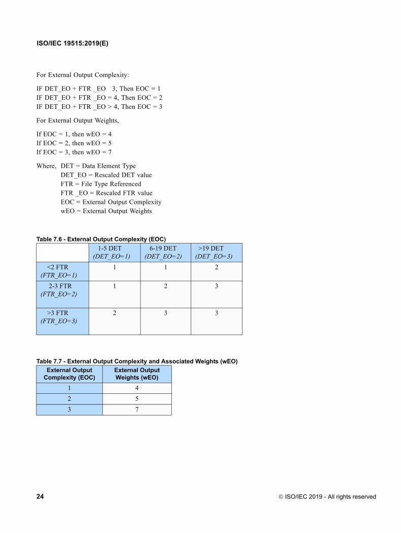
Second, determine the External Ouput Complexity and Weighted External Output Size using the following rules. The calculation of Weighted External Output Size is presented in tabular form in Table 7.6 and Table 7.7.
For External Output Files:
If 1 DET 5, Then DET_EO = 1If 6 DET 19, Then DET_EO = 2If DET > 19, Then DET_EO = 3If FTR < 2, Then FTR _EO = 1If 2 FTR 3, Then FTR _EO = 2If FTR > 3, Then FTR _EO = 3
Table 7.4 - External Input Complexity (EIC)
1-4 DET(DET_E1=1)
5-15 DET (DET_E1=2)
>15 DET (DET_E1=3)
<2 FTR (FTR_EI=1)
1 1 2
2 FTR (FTR_EI=2)
1 2 3
>2 FTR (FTR_EI=3)
2 3 3
Table 7.5 - External Input Complexity and Associated Weights (wEI)
External Input Complexity (EIC)
External Input Weights (wEI)
1 3
2 4
3 6
ISO/IEC 2019 - All rights reserved 23
ISO/IEC 19515:2019(E)
For External Output Complexity:
IF DET_EO + FTR _EO 3, Then EOC = 1IF DET_EO + FTR _EO = 4, Then EOC = 2IF DET_EO + FTR _EO > 4, Then EOC = 3
For External Output Weights,
If EOC = 1, then wEO = 4If EOC = 2, then wEO = 5If EOC = 3, then wEO = 7
Where, DET = Data Element TypeDET_EO = Rescaled DET valueFTR = File Type ReferencedFTR _EO = Rescaled FTR valueEOC = External Output ComplexitywEO = External Output Weights
Table 7.6 - External Output Complexity (EOC)
1-5 DET(DET_EO=1)
6-19 DET (DET_EO=2)
>19 DET (DET_EO=3)
<2 FTR (FTR_EO=1)
1 1 2
2-3 FTR (FTR_EO=2)
1 2 3
>3 FTR (FTR_EO=3)
2 3 3
Table 7.7 - External Output Complexity and Associated Weights (wEO)
External Output Complexity (EOC)
External Output Weights (wEO)
1 4
2 5
3 7
24 ISO/IEC 2019 - All rights reserved

ISO/IEC 19515:2019(E)
7.4 Determine Function Point Size
The final step of the automated Function Point sizing process shall be to calculate the overall Function Point Size of the application. The Function Point Size of the application shall be calculated applying the weights in Table 7.3, Table 7.5, and Table 7.7 to the respective contents of their cells as displayed in Table 7.8. These weighted sums shall then be summed to determine the final Function Point Size of the application according to the following formula.
Automated Function Point Size (AFPs) = (ILFs + EIFs + EIs + Eos)
Where
ILFs = 7 Σ ILFDFC=1 + 10 Σ ILFDFC=2 + 15 Σ ILFDFC=3
EIFs = 5 Σ EIFDFC=1 + 7 Σ EIFDFC=2 + 10 Σ EIFDFC=3
EIs = 3 Σ EIEIC=1 + 4 Σ EIEIC=2 + 6 Σ EIEIC=3
Eos = 4 Σ EOEOC=1 + 5 Σ EOEOC=2 + 7 Σ EOEOC=3
And,
ILFDFC=x = Internal Logical Files whose Data Function Complexity (DFC) = X, where 1 ≤ X ≤ 3.
EIFDFC=x = External Interface Files whose Data Function Complexity (DFC) = X, where 1 ≤ X ≤ 3.
EIEIC=x = External Inputs whose External Input Complexity (EIC) = X, where 1 ≤ X ≤ 3.
EOEOC=x = External Outputs whose External Output Complexity (EOC) = X, where 1 ≤ X ≤ 3.
7.5 Output Generation
The last step of the automated process shall generate the output. The output should be a human readable report that contains enough detail to answer the following questions:
• What is the functional size of the application?
• Where is the application complexity?
• What are the assumptions used in the process?
Table 7.8 - Calculation of Automated Function Point Size (AFPs)
Complexity Category
SizeLow (1) Average (2) High (3)
ILF 7 Σ ILFDFC=1 10 Σ ILFDFC=2 15 Σ ILFDFC=3 ILFs = Σ row
EIF 5 Σ EIFDFC=1 7 Σ EIFDFC=2 10 Σ EIFDFC=3 EIFs = Σ row
EI 3 Σ EIEIC=1 4 Σ EIEIC=1 6 Σ EIEIC=1 EIs = Σ row
EO 4 Σ EOEOC=1 5 Σ EOEOC2 7 Σ EOEOC3 EOs = Σ row
AFPs AFPs = Σ Column
ISO/IEC 2019 - All rights reserved 25
ISO/IEC 19515:2019(E)
The generated output file format shall be a common text file format (e.g., .txt or .csv) to allow for importing to other tools such as Excel or a commercial software estimating package. The type and characteristics of Data Function and Transactional Function’s underlying source code shall be described using KDM terminology.
The output shall include the following artifacts:
• Overall function point size.
• List of Data Functions (IFLs, EIFs), including DETs, RETs, and weightings.
• List of Transactional Functions EI, EO (can be either a logical EO or EQ), including DETs, FTRs, and weightings.
• Mapping between Data Functions and Transactional Functions.
• A list of all instances where a pattern specified in the input is matched but ignored and the reason why the instance was ignored. For example, a list of ignored Data Structures and the input pattern that matched each one, i.e., *STATUS (Status entities).
• Size for each function.
• Location of each Data Function and Transactional Function underlying elements in the source code.
• List of External APIs that are used by the application.
• A complete list of inputs used by to generate the outputs.
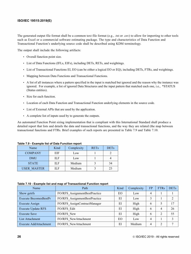
An automated Function Point sizing implementation that is compliant with this International Standard shall produce a detailed report that lists and details the data and transactional functions, and the way they are related (the map between transactional functions and FTRs. Brief examples of such reports are presented in Table 7.9 and Table 7.10.
Table 7.9 - Example list of Data Function report
Name Kind Complexity RETs DETs
COMPANY EIF Low 1 2
DMU ILF Low 1 4
STATE ILF Medium 3 34
USER_MASTER ILF Medium 3 23
Table 7.10 - Example list and map of Transactional Function report
Name Path Kind Complexity FP FTRs DETs
Show getrfs FO/RFS_AssignmentBestPractice EO Low 4 1 1
Execute BecomesBestPr FO/RFS_AssignmentBestPractice EI Low 3 1 2
Execute Assign FO/RFS_AssignContractManager EI High 6 5 17
Execute Update RFS FO/RFS_Edit EI High 6 4 26
Execute Save FO/RFS_New EI High 6 2 55
List Attachment FO/RFS_NewAttachment EO Low 4 1 3
Execute AddAttachment FO/RFS_NewAttachment EI Medium 4 2 7
26 ISO/IEC 2019 - All rights reserved

ISO/IEC 19515:2019(E)
7.6 Structured Metrics Meta-Model (SMM) Representation
7.6.1 Computing Automated Function Point Size
In this sub clause the Automated Function Point International Standard is represented in the Structured Metrics Meta-Model (SMM) and represented in UML diagrams. Figure 7.1 presents the SMM representation of how Automated Function Point Size is calculated in Table 7.8 of sub clause 7.4 using the inputs produced in 7.2 through 7.3. Figure 7.1 also displays how the measure of AutomateFunctionPointSize is positioned within the formal structure of the SMM.
Figure 7.1 - Class: AutomatedFunctionPointSize
7.6.2 Computing External Output Size
Figure 7.2 presents the SMM representation of how Weighted External Outputs are calculated using Table 7.6 and Table 7.7 from sub clause 7.3.
ISO/IEC 2019 - All rights reserved 27

ISO/IEC 19515:2019(E)
Figure 7.2 - Class:ExternalOutputSize
28 ISO/IEC 2019 - All rights reserved

ISO/IEC 19515:2019(E)
7.6.3 Computing External Input Size
Figure 7.3 presents the SMM representation of how Weighted External Inputs are calculated using Table 7.4 and Table 7.5 from sub clause 7.3.
Figure 7.3 - Class: ExternalInputSize
ISO/IEC 2019 - All rights reserved 29

ISO/IEC 19515:2019(E)
7.6.4 Computing Internal Logical File Size and External Interface File Size
Figure 7.4 presents the SMM representation of how Internal Logical File Size and External Interface File Size are calculated using Table 7.2 and Table 7.3 from sub clause 7.2.
30 ISO/IEC 2019 - All rights reserved

ISO/IEC 19515:2019(E)
Figure 7.4 - Classes: InternalLogicalFileSize and ExternalInterfaceFileSize
ISO/IEC 2019 - All rights reserved 31

ISO/IEC 19515:2019(E)
32 ISO/IEC 2019 - All rights reserved

ISO/IEC 19515:2019(E)
8 References
Albrecht, A. (1979). Measuring application development productivity. In Proceedings of the Joint SHARE/GUIDE IBM Applications Development Symposium. Monterey, CA: IBM, 83-92.
Albrecht, A. (1981). Application Development and Maintenance Measurement and Analysis Guidelines. White Plains, NY: IBM.
CAST (2009). CAST Function Points Estimation Technology. http://www.castsoftware.com
Consortium for IT Software Quality (2010). http://it-cisq.org/
Garmus, D. & Herron, D. (1996). Measuring the Software Process: A Practical Guide to Functional Measurements. Upper Saddle River, NJ: Prentice Hall.
Garmus, D. & Herron, D. (2001). Function Point Analysis. Boston: Addison Wesley.
IFPUG CPM. Function Point Counting Practices Manual, Release 4.3.1. ISBN 978-0-9753783-4-2
ISBSG (2010). Field Descriptions: Data Release 11. www.isbsg.org.
ISO (2009). ISO/IEC 20926:2009 Software and systems engineering—Software measurement—IFPUG functional size measurement method 2009. Geneva: International Organization for Standardization.
ISO (2005). ISO/IEC 24570:2005 Software engineering—NESMA functional size measurement method version 2.1—Definitions and counting guidelines for the application of Function Point Analysis. Geneva: International Organization for Standardization.
ISO (2011). ISO/IEC 25010 Systems and software engineering—Systems and software Quality Requirements and Evaluation (SQuaRE)—System and software quality models. Geneva: International Organization for Standardization.
OutSystems (2011). OutSystems Agile Platform. http://www.outsystems.com
ISO/IEC 2019 - All rights reserved 33

ISO/IEC 19515:2019(E)
34 ISO/IEC 2019 - All rights reserved