information society technologies (ist) … · c.1.4 mapid writing and reading the shared memory ......
TRANSCRIPT

INFORMATION SOCIETY TECHNOLOGIES (IST)PROGRAMME
A Scaleable Monitoring Platform for the InternetContract No. IST-2001-32404
D1.3 “Detailed Architecture Design”
Abstract: This document describes the detailed SCAMPI Architecture. It complements deliver-able D1.1 “High-level SCAMPI architecture and components”, which provided an overview of theSCAMPI architecture and deliverable D1.2 “SCAMPI architecture and component design” which pro-vided a more detailed view and thorough treatment of the Monitoring Application Programming Inter-face (MAPI).
This deliverable focuses on providing a detailed software architecture for the SCAMPI monitoringsystem as described in section 5. Based on a MAPI daemon (mapid) and specialized hardware, theproposed architecture combines monitoring needs received from different clients and implements themin the most efficient way.
Contractual Date of Delivery October 31st 2003Actual Date of Delivery November 13th 2003Deliverable Security Class PublicEditor Evangelos Markatos
The SCAMPI Consortium consists of:
TERENA Coordinator The NetherlandsIMEC Principal Contractor BelgiumFORTH Principal Contractor GreeceLIACS Principal Contractor The NetherlandsNETikos Principal Contractor ItalyUninett Principal Contractor NorwayCESNET Principal Contractor Czech RepublicFORTHnet Principal Contractor GreeceMasaryk University Principal Contractor Czech RepublicSiemens Principal Contractor Germany

[email protected] 2 November 13th, 2003
Contents
1 Introduction 91.1 Motivation - What is the problem? . . . . . . . . . . . . . . . . . . . . . . . . . . . . 9
1.1.1 The Wild Spread of Cyber-Attacks . . . . . . . . . . . . . . . . . . . . . . . . 91.1.2 Friendly Fire on the Internet . . . . . . . . . . . . . . . . . . . . . . . . . . . 111.1.3 The Need for Internet Traffic Monitoring . . . . . . . . . . . . . . . . . . . . 121.1.4 The Benefits of Internet Traffic Monitoring . . . . . . . . . . . . . . . . . . . 12
1.2 The Challenges of Network Monitoring . . . . . . . . . . . . . . . . . . . . . . . . . 141.2.1 A Babel of Monitoring Tools and Languages . . . . . . . . . . . . . . . . . . 141.2.2 The network speed challenge . . . . . . . . . . . . . . . . . . . . . . . . . . . 151.2.3 Addressing the challenges . . . . . . . . . . . . . . . . . . . . . . . . . . . . 15
1.3 Roadmap . . . . . . . . . . . . . . . . . . . . . . . . . . . . . . . . . . . . . . . . . 17
2 Network Monitoring Applications 192.1 Packet Capture . . . . . . . . . . . . . . . . . . . . . . . . . . . . . . . . . . . . . . 20
2.1.1 Libpcap Interface . . . . . . . . . . . . . . . . . . . . . . . . . . . . . . . . . 202.1.2 Packet Capture Application . . . . . . . . . . . . . . . . . . . . . . . . . . . 20
2.2 Traffic Summary Reporting . . . . . . . . . . . . . . . . . . . . . . . . . . . . . . . . 202.2.1 Accounting Application . . . . . . . . . . . . . . . . . . . . . . . . . . . . . 202.2.2 Host Tracking Application . . . . . . . . . . . . . . . . . . . . . . . . . . . . 222.2.3 Flow Record Export Application . . . . . . . . . . . . . . . . . . . . . . . . . 232.2.4 Flow-based Reporting . . . . . . . . . . . . . . . . . . . . . . . . . . . . . . 23
2.3 Threshold Alerting . . . . . . . . . . . . . . . . . . . . . . . . . . . . . . . . . . . . 242.4 Quality of Service Monitoring . . . . . . . . . . . . . . . . . . . . . . . . . . . . . . 242.5 Security Applications . . . . . . . . . . . . . . . . . . . . . . . . . . . . . . . . . . . 26
2.5.1 Intrusion Detection Application . . . . . . . . . . . . . . . . . . . . . . . . . 262.5.2 Denial of Service (DoS) Attack Detection Application . . . . . . . . . . . . . 26
3 Overall System Architecture 293.1 Hardware . . . . . . . . . . . . . . . . . . . . . . . . . . . . . . . . . . . . . . . . . 293.2 Software . . . . . . . . . . . . . . . . . . . . . . . . . . . . . . . . . . . . . . . . . . 29
4 Hardware Architecture 314.1 SCAMPI monitoring adapter . . . . . . . . . . . . . . . . . . . . . . . . . . . . . . . 31
4.1.1 Introduction . . . . . . . . . . . . . . . . . . . . . . . . . . . . . . . . . . . . 314.1.2 COMBO6 motherboard . . . . . . . . . . . . . . . . . . . . . . . . . . . . . 314.1.3 Interface card . . . . . . . . . . . . . . . . . . . . . . . . . . . . . . . . . . . 32
3

CONTENTS
4.1.4 Firmware . . . . . . . . . . . . . . . . . . . . . . . . . . . . . . . . . . . . . 334.1.5 Driver . . . . . . . . . . . . . . . . . . . . . . . . . . . . . . . . . . . . . . . 344.1.6 Feasibility study . . . . . . . . . . . . . . . . . . . . . . . . . . . . . . . . . 354.1.7 Combo6 adapter to Combo6 driver interface . . . . . . . . . . . . . . . . . . . 364.1.8 Booting . . . . . . . . . . . . . . . . . . . . . . . . . . . . . . . . . . . . . . 374.1.9 CAM . . . . . . . . . . . . . . . . . . . . . . . . . . . . . . . . . . . . . . . 374.1.10 I/O queues . . . . . . . . . . . . . . . . . . . . . . . . . . . . . . . . . . . . 374.1.11 comboctl utility . . . . . . . . . . . . . . . . . . . . . . . . . . . . . . . . . . 38
4.2 The DAG card . . . . . . . . . . . . . . . . . . . . . . . . . . . . . . . . . . . . . . . 414.2.1 Timestamp format . . . . . . . . . . . . . . . . . . . . . . . . . . . . . . . . 424.2.2 The DAG API . . . . . . . . . . . . . . . . . . . . . . . . . . . . . . . . . . 42
4.3 Intelligent Routers . . . . . . . . . . . . . . . . . . . . . . . . . . . . . . . . . . . . 434.3.1 Overview . . . . . . . . . . . . . . . . . . . . . . . . . . . . . . . . . . . . . 434.3.2 Traffic Filtering and Mirroring Overview . . . . . . . . . . . . . . . . . . . . 444.3.3 Configuring Traffic Filtering and Mirroring . . . . . . . . . . . . . . . . . . . 46
4.4 The IXP1200 network processor . . . . . . . . . . . . . . . . . . . . . . . . . . . . . 474.4.1 APIs . . . . . . . . . . . . . . . . . . . . . . . . . . . . . . . . . . . . . . . 48
4.5 Commodity Interfaces . . . . . . . . . . . . . . . . . . . . . . . . . . . . . . . . . . 494.5.1 Commodity Interfaces in Promiscuous Mode . . . . . . . . . . . . . . . . . . 494.5.2 The commodity adapter API . . . . . . . . . . . . . . . . . . . . . . . . . . . 50
5 Software Structure 515.1 The MAPI daemon . . . . . . . . . . . . . . . . . . . . . . . . . . . . . . . . . . . . 51
5.1.1 mapidcom . . . . . . . . . . . . . . . . . . . . . . . . . . . . . . . . . . . . 515.1.2 Admission Control and Resource Costs . . . . . . . . . . . . . . . . . . . . . 535.1.3 The libscampi . . . . . . . . . . . . . . . . . . . . . . . . . . . . . . . . . . . 555.1.4 The drivers . . . . . . . . . . . . . . . . . . . . . . . . . . . . . . . . . . . . 575.1.5 mapidlib . . . . . . . . . . . . . . . . . . . . . . . . . . . . . . . . . . . . . 57
5.2 Kernel-based Software . . . . . . . . . . . . . . . . . . . . . . . . . . . . . . . . . . 595.2.1 The combo6 driver . . . . . . . . . . . . . . . . . . . . . . . . . . . . . . . . 59
5.3 SNMP . . . . . . . . . . . . . . . . . . . . . . . . . . . . . . . . . . . . . . . . . . . 625.3.1 Management functions . . . . . . . . . . . . . . . . . . . . . . . . . . . . . . 625.3.2 SNMP Access . . . . . . . . . . . . . . . . . . . . . . . . . . . . . . . . . . 645.3.3 Using the SCAMPI MIB . . . . . . . . . . . . . . . . . . . . . . . . . . . . . 68
5.4 Monitoring in IPv6 networks . . . . . . . . . . . . . . . . . . . . . . . . . . . . . . . 695.4.1 Monitoring DWDM links and other link layer technologies . . . . . . . . . . . 69
6 MAPI Definition 716.1 Passive Monitoring MAPI . . . . . . . . . . . . . . . . . . . . . . . . . . . . . . . . 71
6.1.1 Creating and Terminating Network Flows . . . . . . . . . . . . . . . . . . . . 716.1.2 Reading packets from a flow . . . . . . . . . . . . . . . . . . . . . . . . . . . 736.1.3 Applying functions to Network Flows . . . . . . . . . . . . . . . . . . . . . . 736.1.4 Packet formats . . . . . . . . . . . . . . . . . . . . . . . . . . . . . . . . . . 756.1.5 Flow Records . . . . . . . . . . . . . . . . . . . . . . . . . . . . . . . . . . . 756.1.6 Loadable Functions . . . . . . . . . . . . . . . . . . . . . . . . . . . . . . . . 796.1.7 Some More Complex Monitoring Examples . . . . . . . . . . . . . . . . . . . 826.1.8 Implementation issues for MAPI . . . . . . . . . . . . . . . . . . . . . . . . . 84
[email protected] 4 November 13th, 2003

CONTENTS
6.1.9 Options for MAPI Interfaces . . . . . . . . . . . . . . . . . . . . . . . . . . . 866.2 MAPI vs. Other Approaches . . . . . . . . . . . . . . . . . . . . . . . . . . . . . . . 866.3 Applications that use multiple observation points . . . . . . . . . . . . . . . . . . . . 87
6.3.1 The Remote MAPI . . . . . . . . . . . . . . . . . . . . . . . . . . . . . . . . 876.3.2 Creating multiple network flows . . . . . . . . . . . . . . . . . . . . . . . . . 88
7 Summary 91
A Language for Network Flow Conditions 93
B Predefined Functions for Network Flows 95
C Functions and attributes for admission control 99C.1 Attributes for assertion and assertion examples . . . . . . . . . . . . . . . . . . . . . 99
C.1.1 The scampi auth datatype . . . . . . . . . . . . . . . . . . . . . . . . . . . . 99C.1.2 The flow auth datatype . . . . . . . . . . . . . . . . . . . . . . . . . . . . . . 100C.1.3 The scampi resources datatype . . . . . . . . . . . . . . . . . . . . . . . . . . 100C.1.4 mapid writing and reading the shared memory . . . . . . . . . . . . . . . . . . 100
D Man pages for MAPI functions 101D.1 MAPI functions . . . . . . . . . . . . . . . . . . . . . . . . . . . . . . . . . . . . . . 101D.2 MAPI Variables . . . . . . . . . . . . . . . . . . . . . . . . . . . . . . . . . . . . . . 104D.3 Variables for Hierarchical Flows . . . . . . . . . . . . . . . . . . . . . . . . . . . . . 108
E Header Files 111E.1 mapi.h . . . . . . . . . . . . . . . . . . . . . . . . . . . . . . . . . . . . . . . . . . . 111E.2 mapidlib.h . . . . . . . . . . . . . . . . . . . . . . . . . . . . . . . . . . . . . . . . . 112E.3 libscampi.h . . . . . . . . . . . . . . . . . . . . . . . . . . . . . . . . . . . . . . . . 115
F FFPF 119F.1 FFPF on the IXP1200 . . . . . . . . . . . . . . . . . . . . . . . . . . . . . . . . . . . 120
F.1.1 Basics . . . . . . . . . . . . . . . . . . . . . . . . . . . . . . . . . . . . . . . 120F.1.2 Design details . . . . . . . . . . . . . . . . . . . . . . . . . . . . . . . . . . . 122F.1.3 FFPF API and MAPI details . . . . . . . . . . . . . . . . . . . . . . . . . . . 122
G SNMP access 125G.1 SCAMPI MIB . . . . . . . . . . . . . . . . . . . . . . . . . . . . . . . . . . . . . . . 125
[email protected] 5 November 13th, 2003


List of Figures
1.1 The geographic coverage of the sapphire worm on January 25th 2003. The photo-graph is courtesy of www.caida.org . . . . . . . . . . . . . . . . . . . . . . . . . . . . 10
1.2 Traffic Distribution of the network of the University of Wisconsin for the week7-13 Sept. 2003. The photograph is courtesy of wwwstats.net.wisc.edu . . . . . . . . 13
1.3 Connectivity and speed of GEANT: the European Research Network. The photo-graph is courtesy of GEANT. . . . . . . . . . . . . . . . . . . . . . . . . . . . . . . . 16
2.1 Accounting architecture . . . . . . . . . . . . . . . . . . . . . . . . . . . . . . . . . . 212.2 Flow-based reporting . . . . . . . . . . . . . . . . . . . . . . . . . . . . . . . . . . . 232.3 Architecture for QoS monitoring in a CDN . . . . . . . . . . . . . . . . . . . . . . . 252.4 A content distribution network as a QoS monitoring application . . . . . . . . . . . . 26
3.1 The SCAMPI network monitoring system. . . . . . . . . . . . . . . . . . . . . . . 30
4.1 COMBO6 motherboard . . . . . . . . . . . . . . . . . . . . . . . . . . . . . . . . . . 324.2 Structure of the adapter firmware . . . . . . . . . . . . . . . . . . . . . . . . . . . . . 334.3 Parallelized approach for 10 Gb/s processing . . . . . . . . . . . . . . . . . . . . . . 354.4 I/O queues (a) . . . . . . . . . . . . . . . . . . . . . . . . . . . . . . . . . . . . . . 394.5 I/O queues (b) . . . . . . . . . . . . . . . . . . . . . . . . . . . . . . . . . . . . . . 404.6 DAG architecture . . . . . . . . . . . . . . . . . . . . . . . . . . . . . . . . . . . . . 414.7 Main components of the IXP1200 . . . . . . . . . . . . . . . . . . . . . . . . . . . . 474.8 SCAMPI monitoring system based on commodity-only network interfaces. . . . . 49
5.1 The main modules of the MAPI monitoring system. . . . . . . . . . . . . . . . . . 525.2 SCAMPI MIB . . . . . . . . . . . . . . . . . . . . . . . . . . . . . . . . . . . . . . . 65
7


Chapter 1
Introduction
1.1 Motivation - What is the problem?
1.1.1 The Wild Spread of Cyber-Attacks
As networks get faster and as network-centric applications get more complex, our understanding of theInternet continues to diminish. Nowadays, we frequently discover, to our surprise, that there exist newaspects of Internet behavior that are either unknown or poorly understood. A couple of years ago, forexample, the world was surprised to learn that more than 4,000 Denial-of-Service (DoS) attacks arebeing launched on the Internet every week [19]. This surprising result attracted the interest of publicand of media together 1. Although at that time lots of people had heard about Denial-of-service attacks,most of them did not really know that their magnitude was so high. Most of them they were not simplyaware of the wars raging on the Internet.
To make matters worse, besides DoS attacks, malicious self-replicating programs (called wormsin the colorful language of computers) continue to plague our networks, to multiply rapidly, and tohave the ability to cause damage of unprecedented magnitude. For example, on the 15th of January2003 at 05:29, the Sapphire (Slammer) Worm was launched on the Internet. Targeting a vulnerabilityin the software of SQL servers, the worm rapidly infected more than 70,000 computers running suchservers. Interestingly enough, it took the worm no more than 30 minutes to infect most of the computersthat could be infected. Actually, during its peak expansion the worm was doubling in size every 8.5seconds. Figure 1.1 shows that geographic coverage of the sapphire worm half an hour (at 06:00) afterthe worm was released. We see that the worm infected close to 75,000 computers practically all overthe Globe even including areas such as the Fidji islands and Greenland. Indeed, Sapphire was the firstworm which demonstrated that worms can spread all over the Globe within a time interval, in whichhuman intervention and response is either limited or better yet not possible at all.
Worms like the Sapphire are usually called flash worms because they have the potential to conquerthe entire Internet within minutes before any human intervention is possible. Interestingly enough,besides rapidly spreading worms, there also exist slowly spreading worms: the stealth worms. Stealthworms capitalize on the fact that automatic worm detection systems usually detect the spread of newworms - not the worms themselves. This is because new worms contain code unknown to worm detec-tion systems, and thus can not be detected. Their spread however, is usually exemplified by a suddenincrease in traffic and/or the existence of peculiar traffic patterns, that can be detected. Stealth worms
1http://www.cnn.com/2001/TECH/internet/05/24/dos.study.idg/http://www.nytimes.com/2001/05/24/technology/24HACK.html
9

CHAPTER 1. INTRODUCTION
Figure 1.1: The geographic coverage of the sapphire worm on January 25th 2003. The photographis courtesy of www.caida.org
spread very slowly trying to elude automatic worm detection systems. Masquerading as ordinary traf-fic, stealth worms attach themselves to popular programs, such as peer-to-peer file sharing systems, andpropagate along with the ordinary traffic of such programs.
Despite our knowledge of worms, a large number of them still roams the Internet. Recently, forexample, the Blaster worm infected more than 400,000 computers. Although not as rapidly spreadingas Sapphire, Blaster is a unique worm in the following sense: after its original release on the Internet,Blaster was quickly followed by Welcia, a good worm whose goal was to combat Blaster 2. Welciaenters computers through the same security hole that Blaster exploits and attempts to download andinstall the software patch that would close the security hole and that would make the computer immuneto Blaster. After patching the local computer, Welcia attempts to invade and patch the other computerswithin the same Intranet. Unfortunately, by being over-eager at searching for other vulnerable machinesto patch, Welcia eventually leads to a situation equivalent to an internal Denial-of-Service attack: theWelcia-infected computers continually probe all the rest of the computers in the Intranet trying to findwhether they are vulnerable to Blaster. To make matters worse, once Welcia installs itself in a computer,it is not programmed to remove itself before 2004. As a result, it was not Blaster, but Welcia that causedmore damage in corporate computers 3. To summarize, over the last few months we have seen Blasterspreading through the Internet, Welcia chasing after Blaster, and security administrators chasing afterboth worms.
In addition to self-replicating worms, viruses are increasingly starting to represent a significantcyber-threat as well. Recent viruses were able to gain access to passwords, bank accounts, and impor-tant personal information. While worms are self-replicating programs that multiply without any humanintervention, viruses usually depend on human help in order to multiply. Masquerading themselves asinteresting content, malicious viruses attach themselves to innocent looking email messages prompt-ing the user to “click” on them. Once uses click on the attachment, the malicious executable startsexecuting and conquering the local computer. One of the most widely spread viruses, the BugBear-B,
2http://www.cnn.com/2003/TECH/internet/08/15/microsoft.blaster/3http://us.cnn.com/2003/TECH/internet/08/19/internet.worm.ap/
[email protected] 10 November 13th, 2003

1.1. MOTIVATION - WHAT IS THE PROBLEM?
recently hit several computers on the Internet where it installed a keyboard logger, a snooping program,that was able to steal passwords and gain access to secret information 4. Keyboard loggers are able tosteal confidential information, such as credit card numbers, despite the fact that users may take all se-curity precautions, such as using secure socket layers or a similar information encryption mechanismfor all their communication with the outside world. This is because secure socket layers protect theinformation from snoopers that reside outside the user’s personal computer, but not from snoopers thathave penetrated the user’s personal computer. Indeed, keyboard loggers are able to steal confidentialinformation before it reaches the secure socket layer, and thus before it is encrypted.
Before users managed to recover from the effects of BugBear-B, a new virus started spreading:Sobig.F Sobig.F has been quite effective and has sent more than 100 million email messages during itsfirst week of activity [29] causing more than one billion dollars of damage 5. However, this billion-dollar damage is rather small compared to what these cyber-attacks can potentially do. So far, theaverage victim of a cyberattack lost no more than a few hours of work trying to find what is wrong withthe system and to upgrade it with the appropriate patches. We should not be fooled, however, by themediocre damage that the current worms have done. These worms and viruses are powerful programsthat can cause massive damage of unprecedented effect. For example, these worms have the ability todestroy (even temporarily) our Internet infrastructure. Such devastating worms have been described indetail in the literature and are known as “Warhol” worms [31]. After spreading in less than 15 minutesto most of its potential victims, a Warhol worm would install itself in startup scripts so that it is alwaysstarted when the machine reboots. It would then overwrite random pieces of non system files while atthe same time it would restore the file modification times to their original value making it difficult to findwhich files have been altered. Although altering random pieces of randomly selected files is slower thandeleting the entire files, it is more difficult to be detected by system administrators. After establishingitself to several millions of computers, the Warhol worm would start a massive Distributed Denial-of-Service attack to major sites including antivirus sites that may contain the patch for the Warhol worm,thus hindering all legitimate users from patching their computers. Effectively, the described Warholworm would shut down the normal operation for most computers connected to the Internet.
1.1.2 Friendly Fire on the Internet
Besides malicious attacks, there also exist non-malicious incidents on the Internet that may have abig negative impact on its operation. For example, it was recently discovered that a “combinationof Microsoft software features and misconfigurations was essentially causing a slowly-paced massivedistributed denial of service (DDoS) attack on the root name server system” [6]. Actually, it wasfound that personal computers running the Windows operating system were sending updates for privateaddresses to root Domain Name Servers (DNSs) without any particular reason. These unnecessaryupdates were consuming a large percentage of root name server resources, which is exactly the sameeffect caused by massive Distributed Denial of Service attacks. Obviously, as an increasingly largerpercentage of computers runs software of a single vendor, such incidents will become increasinglycommon in the future. Indeed, when most computers run the same software, even a small un-noticeablesoftware bug can be magnified and have unexpected results.
4http://www.cnn.com/2002/TECH/internet/10/01/hln.wired.bugbear.virus/5http://theregister.co.uk/content/56/32760.html
[email protected] 11 November 13th, 2003

CHAPTER 1. INTRODUCTION
1.1.3 The Need for Internet Traffic Monitoring
All the above mentioned incidents, whether malicious or not, (i) demonstrate our relatively poor un-derstanding of the Internet, and (ii) show the need for better Internet traffic monitoring. BetterInternet traffic monitoring will not only improve our understanding of the Internet but it will help usimprove its operation by
• providing early warning for new cyberattacks during the first seconds of their spread
• isolating newly discovered cyberattacks during the first minutes of their spread, based on coop-eration with firewalls or other network protection systems
• identifying the sources of unexpected performance problems, such as the friendly-fire problemdescribed above
• providing better traffic characterization, even for applications that want to elude characterization,such as peer-to-peer systems
1.1.4 The Benefits of Internet Traffic Monitoring
Besides dealing with the detection of cyber-security threats, better Internet Traffic Monitoring can helpus tackle a variety of problems. For example, one of the most frequent requests of network adminis-trators is to find out the applications that generate the largest amounts of traffic that flows through themonitored networks. Unfortunately, current network traffic monitoring infrastructures usually do notprovide this kind of information, i.e. current monitoring infrastructures do not provide the necessaryinformation needed to find which applications generate most traffic within a network. This is becauseseveral of the current monitoring systems are based on flow-level statistics, such as those providedby NetFlow [28], IPFIX, and related systems and proposals, which associate applications with staticwell known ports. Such monitoring systems assume, for example, that each application is associatedwith only one static well-known port. Although this is true for several of the traditional applications,most of the emerging applications, such as peer-to-peer systems and video conferencing systems, usea variety of dynamically generated ports. Therefore, traditional ways of monitoring usually end upunable to monitor the network. Let’s take for example figure 1.2 that shows the distribution of trafficamong various applications for the University of Wisconsin for the week of 7-13 September 2003. Thelegend reads that 1.2% of the outgoing traffic is attributed to KaZaa, 0.5% of the outgoing traffic isattributed to Gnutella, 14.4% of the outgoing traffic is attributed to HTTP (the web), etc. What is mostimportant to see, however, is that the penultimate line of the figure legend states that 69.4% of theoutgoing traffic is attributed to “Other” applications, that is, applications besides peer-to-peer systems(such as KaZaa, Gnutella, eDonkey, Napster), besides web, besides ftp, besides Usenet news (nntp),besides email (smtp), besides ICMP, besides real audio/video, etc. It is surprising to see that close to70% of the outgoing traffic of the University of Wisconsin does not belong to any of the known pop-ular sources of traffic. It is interesting to see that close to 70% of the outgoing traffic of a Universitywith well-monitored networks is attributed to applications that we do not currently know. Actually,this surprising effect is probably due to the fact that the methodology used to categorize traffic intoapplications is based on traditional monitoring methods that associate applications with static ports,while an emerging applications of popular applications use dynamic ports. Thus, applications that usedynamic ports, such as KaZaA, seem to consume only 1% of the traffic while previous measurements,form the era when those applications used static ports reported that peer-to-peer applications consumed
[email protected] 12 November 13th, 2003

1.1. MOTIVATION - WHAT IS THE PROBLEM?
Figure 1.2: Traffic Distribution of the network of the University of Wisconsin for the week 7-13Sept. 2003. The photograph is courtesy of wwwstats.net.wisc.edu
the largest portion of traffic [15]. Indeed, analysis based on passive monitoring tools reveals that peer-to-peer applications consume three times more traffic than analysis based on static port numbers [27].As a result, in the above example, traditional monitoring methods cannot account for the 70% of thetraffic, and in the end, network administrators are not able to see which applications consume whichpercentage of the traffic: in the above example they do not know who is using 70% of the network’straffic.
Besides finding the applications that generate the largest amounts of traffic in the networks, systemadministrators are also interested to find out performance bottlenecks in applications running in theirdomain. For example, users frequently complain that accessing a web server is unusually slow, andturn to network administrators to find what is the problem. The problem may be attributed to a slowserver, a buggy protocol implementation, a slow network, a slow client, a lossy connection, etc. Tra-ditional traffic monitoring systems usually provide little information in order to pinpoint this kind ofperformance problem. For example, the mentioned flow-level statistics, although may provide someinsight, are in general of little help in this kind of problem. Advanced network monitoring systemstry to solve the above mentioned problem using active monitoring. In active monitoring, servers peri-odically send a sequence of messages to receivers, record the time when the messages arrive to theirdestination, and based on these measurements, they are able to find network properties such as band-width, latency, loss rate, etc. Although such active monitoring systems may provide insight towards thesolution of the performance problem, in many cases that are still inadequate. For example, if the serverbelongs to a different administrative domain which may not want to cooperate in measurements, such
[email protected] 13 November 13th, 2003

CHAPTER 1. INTRODUCTION
as cnn.com or abc.com, active monitoring systems can not take accurate measurements of traffic arriv-ing to this server. Similarly, active monitoring systems can not usually find out why a particular clientexperiences a particular problem: they can only find out the average performance of source-destinationpair. Therefore, even after using active monitoring and flow-level statistics, a user may not have thenecessary information to deal with the performance problems reported.
1.1.4.1 The SCAMPI Approach
SCAMPI is a step towards improving our understanding of the Internet and towards solving difficultperformance and security problems. Besides understanding and improving the Internet as stated in[21], network monitoring systems in general, and SCAMPI in particular, have several other goals aswell including:
• to help Internet Service Providers and Application service Providers in giving better serviceto their customers through improved billing mechanisms.
• to improve the end-user experience through better network performance achieved in part byinformed network management and traffic engineering methods
• to enhance the security of computer systems connected to the Internet by providing a betterdefense against cyberattacks, such as Denial-of-Service attacks and Intrusion attempts.
1.2 The Challenges of Network Monitoring
1.2.1 A Babel of Monitoring Tools and Languages
From the above examples, it can be easily seen that network monitoring is needed by several differentkinds of users that would like to monitor different aspects of the network traffic. For example, some ofthe users may be interested in viewing aggregate traffic statistics only, while others may be interestedin monitoring (and maybe storing on persistent storage) each and every byte that travels through theirnetwork (e.g. in order to detect cyberattacks). Currently, state-of-the-art tools specialize in solvingonly one subclass of network monitoring problems. For example, there exist several traffic monitoringtools currently being used by ISPs and ASPs that monitor the status of their networks in order to alertadministrators of possible malfunctions. These tools can also monitor the amount of traffic on thevarious segments of the network in order to inform administrators of the network usage and enablethem to make informed traffic engineering decisions. Some of those tools are sophisticated enoughto work both as traffic generators and as traffic analyzers at the same time in order to detect possiblenetwork problems.
Besides the above mentioned tools, there exist monitoring environments specialized in discoveringIntrusion attempts. These environments, also known as Intrusion Detection Systems (IDSs) [1] examineevery packet they observe on the network, trying to detect one of the known intrusion threats. Similar toIDSs, Denial-of-Service attack detection tools monitor the network traffic in order to detect generalizednetwork attacks. Denial-of-Service attack detection systems are frequently integrated into firewalls thatexamine and classify packet headers in order to detect any abnormal increases the network packets,which may indicate the start of an attack.
Finally, besides the traffic-engineering-related and the security-related monitoring tools, there ex-ists a variety of traffic capture tools that focus on capturing (and maybe storing) all network packets
[email protected] 14 November 13th, 2003

1.2. THE CHALLENGES OF NETWORK MONITORING
(possibly along with their payloads) in real-time. Such captured packets are subsequently being usedby network researchers to drive their own research.
Currently, most of the above monitoring tools and environments are based on different sets ofprimitives and functions. For example, traffic monitoring tools are based on the primitives providedby network routers such as NetFlow [28]. On the other hand, traffic capture tools, such as thoseused by NLANR, are based on top of a custom-made hardware-software infrastructure, collectivelyknown as OC3MON [12]. Intrusion detection systems, such as snort [26], have been implementedon top of the libpcap [16] packet capture library, while Denial-of-Service detection systems are be-ing implemented on top of firewalls, which on Linux-based systems are usually implemented on top ofnetfilter and iptables. To make matters worse, commercial vendors frequently use their ownlibraries and standards, contributing even more to the Babel of network monitoring tools and environ-ments, making it even more difficult to write portable network monitoring applications.
1.2.2 The network speed challenge
Computer networks continue to get faster at ever-increasing rates. For example, published resultssuggest that network bandwidth increases at alarming rates doubling every 9-18 months or so [2], anobservation which is usually referred to as “Gilder’s Law”. At the time of this writing the Internetbackbone links of the European research network GEANT run at 2.5 to 10 Gbps (as shown in Figure1.3). As if this exponential increase were not enough, network monitoring applications continue tobecome more complex and more demanding. For example, the first network monitoring applicationsrequired very little information from the monitored network, such as aggregated traffic statistics oraggregated flow statistics. On the contrary, recent monitoring applications demand a significant amountof information, that includes both header and payload data for each and every packet of the network.To make matters worse, monitoring applications add an ever-increasing amount of processing on thecaptured data, such as compute-intensive string matching used for the detection of Internet worms andvarious other forms of cyberattacks.
1.2.3 Addressing the challenges
Having realized the challenges posed by the state-of-the-art tools in network monitoring, SCAMPI rep-resents a bold step towards building an affordable network monitoring system for high-speed networksthat will enable the development of portable applications.
SCAMPI employs a three-pronged approach in order to achieve its goals:
• Standard Monitoring API (MAPI). SCAMPI will define a set of monitoring calls/primitivesthat will be collectively called as MAPI. Monitoring applications will be written using this MAPI.The MAPI will be implemented on top of several platforms, decoupling the development of themonitoring applications from the monitoring environment on top of which the applications willbe executed. Thus, monitoring applications will be written once, and will be able to run on topof any monitoring environment without needing to be re-written.
• Expressive power. Current monitoring application programming interfaces provide little (ifany) expressive power to application programmers. Thus, application programmers are not ableto communicate their monitoring requirements to the underlying network monitoring system. Asa result, frustrated application programmers end up receiving all network packets in the addressspace of their application where they perform the operations they need. As a simple example ofthe poor expressive power of current network monitoring systems, consider a user that wants to
[email protected] 15 November 13th, 2003

CHAPTER 1. INTRODUCTION
Figure 1.3: Connectivity and speed of GEANT: the European Research Network. The photographis courtesy of GEANT.
[email protected] 16 November 13th, 2003

1.3. ROADMAP
sample one out of every 100 packets in order to find the most popular applications that use his/hernetwork. Current network monitoring systems (like libpcap [16], Berkeley Packet Filters [17],and Linux Socket Filters [11]) do not enable users to express such simple sampling requirements.Therefore, users that are interested in receiving just one out of every 100 packets are required toread all packets, and just discard 99 out of every 100 of them. To overcome these limitations,SCAMPI’s MAPI will enable monitoring application programmers to express their requirementsto the underlying monitoring system, which in turn will decide how will these requirements willbe more efficiently implemented.
• Scalability through special-purpose hardware and parallelism. Although network monitor-ing can be performed on top of traditional network adapters, SCAMPI, wherever possible, willexploit specialized network adapters that provide some monitoring functionalities in hardware[12, 18] These adapters contain on-board processors and FPGAs that can be programmed to per-form monitoring functions and off-load the host processor, memory system, and I/O buss frommuch of their load.
1.3 Roadmap
The rest of the deliverable is organized as follows: Chapter 2 outlines the network monitoring appli-cations SCAMPI will support. Chapter 3 presents the overall software and hardware structure of theSCAMPI monitoring system. Chapter 4 presents the alternatives for the hardware infrastructure rangingfrom special-purpose interfaces, to commodity interfaces, to intelligent routers. The chapter focusesespecially on the description of the combo6-based SCAMPI monitoring board. Chapter 5 presents theoverall software structure of the system, focusing especially on the MAPID daemon, the “heart” ofthe software architecture. Chapter 6 presents the definition of MAPI, a somewhat improved version ofwhat has been presented in Deliverable D1.2, and finally chapter 7 summarizes and concludes the de-liverable. In addition, this deliverable provides several appendices that complement the main documentor act as reference manuals.
[email protected] 17 November 13th, 2003


Chapter 2
Network Monitoring Applications
This chapter describes the monitoring applications that are being developed as part of the SCAMPIproject. We will focus on five different types of applications, i.e. pure packet capture, traffic summaryreports, threshold alerting, QoS monitoring and security. An overview is given in Table 2.1.
Type ApplicationFlow Oper-ation
Output
PacketCapture
legacy applications on top oflibpcap classification
full framesor selectedheadersstoring selected packet parts
Traffic Sum-mary
Netflow-like flow records andrelated accounting support
Flow RecordStatistics
FlowRecords
ThresholdAlerting
Threshold checking on trafficentering a node
Flow Statis-tics
Event
Quality ofService
Passive Flow QoS Monitoring flow-basedsampling
statistics
Security
Intrusion detection signature-basedsampling
full frames
DoSdetection
Flow Statis-tics
Events orStatistics
Table 2.1: Application Overview
Pure packet capture will be supported in order to comply with legacy applications that run forexample on top of libpcap [16]. In this case, an important method to reduce the volume of the capturedtraffic stream will be classification and filtering of the packets in the stream. Packet capture will outputfull captured frames or selected headers that can be stored to disk for later analysis. Traffic summaryapplications on the other hand will capture traffic and export flow records. These NetFlow-like flowrecords will for example be very useful in accounting applications. When monitoring networks forthreshold alerting, flow statistics are collected. If a certain threshold for example is exceeded, anasynchronous event is sent to the application. In QoS monitoring, statistics about captured flows arecollected and are sent back to the application. Flow-based sampling will allow the application to keepup with high-speed networks. In security applications such as Intrusion Detection Systems (IDS),
19

CHAPTER 2. NETWORK MONITORING APPLICATIONS
signature-based sampling will be used to filter packets that contain some specified pattern out thestream. The full frame of these sampled packets is sent to the application for analysis. Finally, theDenial-of-Service detection application will monitor network traffic characteristics in order to detectsudden and abnormal changes of traffic statistics that are indications of security attacks.
We chose to implement these applications, not only because of our interest in such applicationsand their importance in network management and traffic engineering, but also because they focus ondifferent capabilities of the system. All applications use different techniques to deal with high-speednetworks. Packet capture focuses on the elimination of packets that are of no interest to the higher layerapplication running on top of packet capture. Traffic summary reduces the size of the flow records,without losing any valuable information, in order to deal for example with the limitations of memorycapacity and PCI bus speed. Threshold alerting in QoS monitoring gather statistics of the flows anduse sampling methods to reduce the captured network flow. Security applications, such as IntrusionDetection Systems, often need to analyse all captured data. In this case, efficient algorithms are neededin both the monitoring platform and the application.
2.1 Packet Capture
Pure packet capture will filter selected packets on a monitored circuit and store full frames or selectedheaders to a disk for a follow-up analysis. It will also support legacy applications that run for exampleon top of libpcap.
2.1.1 Libpcap Interface
The libpcap interface to the MAPI will translate libpcap functions to MAPI calls. This interface willallow any application written on top of libpcap to be executed on a SCAMPI enabled platform. Tosupport these legacy applications, a modified libpcap library will be developed. Using this library incombination with legacy applications, the performance and functionality of the SCAMPI platform canbe compared to traditional libpcap-based systems.
2.1.2 Packet Capture Application
Packet Capture is a very basic monitoring application. It simply captures packets from the wire andsaves them to disk. Some filtering can be done on the incoming stream of packets to obtain onlythose packets that the application is interested in. Furthermore, only certain parts of the packet can beprocessed or saved to disk. If the user is only interested in the headers of the packets belonging to acertain flow, the application can be configured to capture only the requested information.
The Packet Capture application will be implemented on top of the MAPI. It will be possible toapply a chain of filters to the incoming packetstream and save the full frames or selected headers todisk for a follow-up analysis.
2.2 Traffic Summary Reporting
2.2.1 Accounting Application
Internet and Application Service Providers bill their customers based on their actual traffic or networkusage. An accounting application over SCAMPI will provide to an ISP the ability to accurately measure
[email protected] 20 November 13th, 2003

2.2. TRAFFIC SUMMARY REPORTING
Figure 2.1: Accounting architecture
various characteristics of network traffic, improve their services and provide advanced billing mech-anisms and policies. The accounting application should be able to receive or gather input data frommany SCAMPI probes, in order to provide (if needed) aggregated statistics or a more comprehensive”picture” of usage for the whole network. This application will also provide necessary information inorder to find customers whose traffic volume results in a degradation of service quality, or customerswho experience such service quality degradation.
The process of cooperation/integration of SCAMPI platform, the accounting application and thecomponents of a billing system is schematically represented in the figure 2.1.
The accounting application will be based on the SCAMPI platform and the input will be the re-sponse from MAPI on specific requests e.g
• traffic volume that corresponds to a range of IPs (quantitative parameter)
• jitter on packets with high priority between a source and destination host (qualitative parameter)
The output of accounting application will be one or more Service Detail Records (SDRs). An SDRis a record with all the necessary information for the usage of a service or the values of QoS parametersneeded by a billing system. In Table 2.2 there is a high level description of the most important fields ofan SDR.
The rating system is the process that incorporates the definition of tariff elements, the algorithmsto implement various rate plans and the configuration of Service Level Agreement (SLAs). The billing
[email protected] 21 November 13th, 2003

CHAPTER 2. NETWORK MONITORING APPLICATIONS
ID Unique IdentifierUser Specific Info IP address-IP range-Phone number-User nameService Info Parameter measured or monitoredQuantity Traffic volume - Parameter value - Call durationTime Period The date/time period (start-end) of measurementsStatus The status of SDR
Table 2.2: SDR Fields
system produces invoices for customers (charge or credit) based on the service and the respective pric-ing policy. The rating and billing software solutions could be supplementary products in the SCAMPImonitoring platform, in the sense that they can take as input, the output data of the monitoring pro-cess and exploit its advantages and re-adjust accordingly the policies applied to the networked basedservices.
The structure of Forthnet’s existing billing system (FOBIA), follows the scheme presented above.Therefore with the appropriate parameterization it can be integrated with the accounting applicationby defining SDRs in the proper way. Tests will be conducted on real traffic flowing across FORTHnetnetwork.
SCAMPI and applications over it can provide the means to measure efficiently performance andbehaviour at high speed, in order to feed billing components with the meaningful events and billableinformation. Henceforth, the perspective role of SCAMPI is to empower and encourage the adoptionof modern economic and product models in the telecommunications and networking market, based onthe emphasis to
1. qualitative measurable performance rather than quantitative criteria.
2. enable the customer validate the received quality.
2.2.2 Host Tracking Application
In the last years, many European countries approved laws that require ISPs to:
• maintain traffic traces for some time (6 months or more)
• provide facilities for tracking activities performed by customers
If needed (e.g. in case of an investigation), ISPs must provide the government (e.g. police) a secureinterface (e.g. via HTTPS on leased lines not connected to the Internet) to the system that maintainstraffic traces.
Many traffic monitoring applications provide some traffic accounting facilities. Most of these ap-plications have been designed for measuring traffic for billing purposes and do not provide facilities fortracking activities.
Traffic flows (e.g. NetFlow) are commonly used by ISPs for network monitoring. High-end routersused to run the backbone are usually able to emit network flows. However, in some cases routers arenot able to emit flows when running at high speeds because flow probes have limited resource access(mainly CPU) or because flow generation is performed by the main router CPU and not by the ASICscore used to route packets. The consequence is that it is necessary to develop both a software probeand a collector:
[email protected] 22 November 13th, 2003

2.2. TRAFFIC SUMMARY REPORTING
NetflowCollector
SCAMPIIPFIX exporter
flatfiles
ReportGenerator SQL
database
SQL Webinterface
SQ�L CLIinterface
Maintenancescripts
NetFlow/IPFIX
MAPI
CLIinterface
IPFIX
Figure 2.2: Flow-based reporting
• the probe will be used whenever network routers cannot cope with the network speed
• the collector will be responsible for collecting flows generated both by the routers and the soft-ware probes
The probe will be based on MAPI in order to take advantage of the SCAMPI platform. The collectorwill be based on CAPI (Collector API), a new API defined by SCAMPI that eases the creation ofcollector applications. CAPI is responsible for collecting flows, storing them persistently and providingfacilities for performing queries on the flows for the purpose of traffic accounting and activity tracking.
2.2.3 Flow Record Export Application
NetFlow is today one of the most commonly used technologies for monitoring network usage andcollecting information about network traffic. The work of collecting flow records is usually done byrouters which export the flow records to some collector. One problem with this is that as the networkspeed increases, most routers are not able to do full flow analysis and have to use sampling to keep up.
The flow record exporter application will use the SCAMPI platform to export flow records usingthe IPFIX protocol and will be used at high speeds where routers can not deliver flow records withoutusing sampling. The flow exporter is a user level program that uses MAPI to produce flow records andthat will act like a filter distributing the flow records to recipients like files or standard output as wellas providing IPFIX export.
2.2.4 Flow-based Reporting
Flow-based reports uses the information available in flow records to produce a broad range of reportsshowing various information about the network traffic. Users normally accesses the reports throughsome web based interface which allows the users to select the report type and time period.
This application will generate flow based reports based on the input from NetFlow/IPFIX records.The application will take advantage of the SCAMPI flow record exporter which can export extra in-formation not normally found in flow records to generate novel reports not available by other existingapplications.
Figure 2.2 shows the various components of this application. All the components will be imple-mented as part of the SCAMPI project although some of them will be heavily based on already existingsoftware like FlowTools.
The web interface will allow users to browse the reports. This interface will be implemented so thatit will be easy to support new types of reports. There will also be access control support so that accessto some or all reports can be restricted.
[email protected] 23 November 13th, 2003

CHAPTER 2. NETWORK MONITORING APPLICATIONS
At the end of the project this application will collect flow records from the Flow record exporter ap-plication and generate reports based on traffic from a production network. A successful implementationwill be able to generate reports based on the traffic from a 10Gbit/s production network.
2.3 Threshold Alerting
Threshold alerting is a common part of network management platforms and is supported in both SNMP(through traps) and COPS (through the COPS reporting mechanisms). There are several uses for thesetype of alerts which all share a common requirement to the SCAMPI platform: the applications are notgenerally interested in monitoring information, but want to receive information asynchronously.
In order to configure a threshold alerting application we need to supply the MAPI with a monitoringjob that contains:
• zero or more classification rules to narrow the overall traffic volume.
• a metering or counting function.
• a threshold checking function.
By using a blocking read on the results of the latter, we can be notified whenever a threshold hasbeen exceeded.
The above mechanism will be incorperated as part of a short-term traffic engineering research. Inthis context we need to split traffic entering from a interface on two paths according to a given weightdistribution 1. A first remark is that in this case we have taken a router and scampi device together inone device (using an ad-hoc extension of the SCAMPI software). Secondly, the sampler and meteringblocks remain static through the lifetime of the system (only the mapping to an output can be changed).The main goal of this application is to show the functionality of the event-based reaction to monitoring,and this is accomplished by building a feedback loop between the monitoring of the buckets, throughthe MAPI to a local tunnel management point, and a possible resulting reconfiguration (re-mapping).
2.4 Quality of Service Monitoring
QoS-monitoring analyses the behaviour of a specified (e.g. SLS monitoring) or random stream (e.g.CoS monitoring) throughout a system under observation (ranging from a single link to a concatenationof ISPs).
We will develop and implement a two-layered architecture for QoS monitoring, i.e. a QoS mon-itoring layer and an application layer. The monitoring layer, belonging to a single Internet ServiceProvider (ISP), will provide end-to-end QoS statistics of the observed network to the application layer.These statistics include packet loss, network throughput and delay. Any application in the upper layercan request these end-to-end QoS statistics from the monitoring layer.
In the current client-server architecture, a single server serves multiple clients. This approachhowever has some significant drawbacks. The quality of the offered services often degrades when forexample (i) the server cannot handle the load, (ii) the intermediate network gets congested or (iii) theexperienced latency is too high. To tackle the performance problems of this classical client-serverapproach, a lot of alternative techniques have already been developed. In order to reduce the latency
1this traffic engineering functionality is commonly refered to as tunnel management and is applicable to several areas likeMPLS-based TE, where traffic is mapped on an LSP or Ethernet-based TE where traffic is mapped to a VLAN/spanning tree
[email protected] 24 November 13th, 2003

2.4. QUALITY OF SERVICE MONITORING
CDN-layer
Network Layer
Content Server
Content Server
Content Server
Content Client
CDN Control
SCAMPI
End-to-End Statistics
Figure 2.3: Architecture for QoS monitoring in a CDN
for example, caches can be placed in the network, close to the end user. Instead of serving clients usingonly a single server, server farms in combination with load balancing can increase the service rate ofthe incoming requests. Despite such efforts, end users still often encounter poor service quality whenretrieving bandwidth-intensive content such as audio and video from the Internet. Therefore, ContentDistribution Networks have been introduced. In a Content Distribution Network (CDN), the content isreplicated to different surrogate servers at the edges of the network. This way, the content only has topass a few nodes in order to reach the end user, resulting in better quality of service. The CDN will usea Replica Placement Algorithm (RPA) to decide where to replicate which content. Likewise, ContentServer Selection Algorithms are used to direct client requests to an optimal server (i.e. a server that candeliver the service with the highest quality).
However, the main problem in the current CDNs is that both algorithms rely in most cases onsome raw measurements such as round-trip-time and hop-count. CDNs simply do not have enoughinformation about the current state of the network resources and content servers, resulting in non-optimal decisions of the current algorithms. In this application, we will develop a QoS monitoringlayer that offers the requested statistics to, for instance, a CDN application.
Figure 2.3 depicts the architecture we use for QoS monitoring. The Network layer will provide net-work QoS statistics to the application layer, f.e. a CDN application, above. Based on this information,the CDN layer can replace its content, i.e. run Replica Placement Algorithms, and assign clients tocertain content servers, i.e. Content Server Selection. The network layer is part of a single ISP, whichprovides (on-demand) end-to-end QoS statistics to the application layer, without revealing any sensi-tive network topology information to the outside world. This way, an application can obtain end-to-endstatistics between two access points of the network.
The integration of the monitoring layer with the SCAMPI architecture is illustrated in Figure 2.4.Based on hashing-based sampling (trajectory sampling) or classification, the QoS parameters are mea-sured. This information will be configured in the monitoring agents (i.e. the access points) throughoutthe MAPI. The results of the individual observation points are correlated in a centralized database.
[email protected] 25 November 13th, 2003

CHAPTER 2. NETWORK MONITORING APPLICATIONS
SCAMPI device
SCAMPI device
Distributed MAPI
Hashing-Based Sampling
Flow Summary
Central Database
Flow Correlation
Figure 2.4: A content distribution network as a QoS monitoring application
2.5 Security Applications
2.5.1 Intrusion Detection Application
Network-based Intrusion Detection is a research and development area that aims to improve the securityof our cyberinfrastructure through the early detection of intrusion attempts. Network-based IntrusionDetection is usually deployed in the core (or the edge) of the Internet in order to identify possible intru-sions as they are being launched. After a possible intrusion is identified, all the information regardingthe intrusion is being logged, and the administrators of the system are (optionally) being alerted. Theadministrators, in turn, may take corrective measures to reduce the effects of this intrusion and possiblypatch the security hole that led to the intrusion.
Network-based Intrusion Detection Systems are usually based on a set of rules (also called signa-tures). Each possible type of intrusion is described by one or more rules. For example, the followingrule describes an attempt by an outsider to become super-user (i.e. root) in one of the local systems:OUTSIDE NETWORK → LOCAL NETWORK TCP 23 content ”su root”. The above rule states thatif a packet is sent from a computer located in the OUTSIDE NETWORK (an alias for all computersoutside the monitored organization) towards a computer in the LOCAL NETWORK (an alias for allcomputers in the monitored organization) on port 23 (the telnet port) using the protocol TCP, and thepayload of the packet contains the substring ”su root”, then this is a possible intrusion attempt. In aNetwork-based Intrusion Detection System each packet is checked against every rule. If the packetmatches a rule, it is logged and the administrators may be notified.
We plan to write an open-source Intrusion Detection application using the MAPI interface. We willcapitalize on our experience with similar publicly available applications, such as SNORT [26], in orderto optimize the application for high-speed networks. The application will detect intrusions based on awell-known set of rules, such as the one distributed by SNORT.
2.5.2 Denial of Service (DoS) Attack Detection Application
A Denial of Service attack detection application has the goal of detecting attacks that attempt to disruptthe ability of a provider to offer service, at a particular performance level, to legitimate users. DoSattacks typically involve flooding a particular network node or server with traffic at a rate much higherthan the node or server can handle. Recent measurements indicate that over 90% of DoS attacks involveTCP traffic, with the most common being TCP SYN attacks. TCP SYN attacks involve sending SYNpackets, thus starting the TCP handshake, without sending corresponding FIN packets, hence without
[email protected] 26 November 13th, 2003

2.5. SECURITY APPLICATIONS
completing it and thereby consuming bandwidth and memory resources. Other DoS attacks includeUDP flood attacks, fragmentation attacks, and ICMP attacks. Key objectives of a DoS attack detectionapplication are the high detection probability, at an early stage of the attack, and with a low false alarmrate.
A common feature of DoS attacks is that they lead to changes in measurable characteristics of anetwork traffic flow. Such characteristics can include the type and size of packets, the number of halfopen connections, and the rate of packets associated with a particular application or port number. Basedon this property of changes in network characteristics, DoS attack detection applications are commonlybased on anomaly detection models, where the behavior of a measurable network characteristic iscompared to its normal behavior, in order to detect significant and abrupt deviations. An advantage ofanomaly detection systems is that they do not require any a priori specification of attack signatures,hence they can detect new types of attacks. One approach for describing normal behavior is to use astatic characterization (also known as operational model), possibly based on measuring the behaviorat some past time; such an approach has the disadvantage of not adapting to changes and trends ofnormal traffic, which may eventually lead to an increased false alarm rate. Another approach is toadapt to the traffic’s normal behavior through continuous monitoring; however, this advantage can turnout to be a disadvantage, if exploited by the attacker to slowly train the detection system to accept abehavior containing an attack. Finally, there are two categories of anomaly detection procedures thatdiffer in how measurements are processed: sequential processing and batch processing. Sequentialprocedures involve continuous processing of measurements in order to detect changes as soon as theyoccur, whereas batch processing procedures involve processing of a batch of data collected within sometime interval, hence result in a fixed detection delay.
The DoS attack detection application will be based on time series models, which take into accountthe time correlations of network traffic measurements. Such an approach still leaves open a number ofpossible procedures for actually detecting when a change has occurred, including standard deviationmodels that detect a deviation beyond some number of standard deviations and change point detec-tion (or hypothesis testing) models. For the latter, two specific algorithms will be implemented: theGeneralized Likelihood Ratio (GLR) algorithm and the Cumulative Sum (CUSUM) algorithm. All theabove methods require measurements of a particular network variable. As indicated above, because themajority of DoS attacks involve TCP traffic, our focus will be on variables related to TCP, such as TCPSYN packets received in some measurement interval, number of half open connections (i.e. differenceof SYN and FIN packets received in some measurement interval), rate of TCP requests, and packetsizes.
s will be on variables related to TCP, such as TCP SYN packets received in some measurementinterval, number of half open connections (i.e. difference of SYN and FIN packets received in somemeasurement interval), rate of TCP requests, and packet sizes.
[email protected] 27 November 13th, 2003


Chapter 3
Overall System Architecture
3.1 Hardware
The overall system architecture of the SCAMPI network monitoring system is shown in Figure 3.1.The system is composed of a Personal Computer coupled with a Hardware Monitor connected to thesystem’s I/O (e.g. PCI) bus. We envision that different instantiations of the SCAMPI system willprobably require different hardware monitors. Low-end monitoring systems will probably use a regularnetwork interface as a hardware monitor. Most network interfaces can be put in a special promiscuousmode in which they receive and propagate to their operating system all the packets that pass thoughtheir network interface, independently of whether the packets were destined to this network interface.
High-end systems may employ a special-purpose adaptor, that has the computing capacity to notonly capture packets, but also to process them and perform some simple (but fast) monitoring function-alities. Endace 1, for example, a New-Zealand-based company, has a complete series of such adaptersfor network monitoring at 1Gbps [18], 2.5 Gbps, and 10 Gbps2.
Cutting-edge systems will employ the SCAMPI adapter based on the combo6 card that can not onlycapture packets at high-speed, but it can also provide filtering and processing capabilities on them.
Other systems may employ various other forms of commodity monitoring hardware. For example,Juniper routers [13] allow users to filter the traffic that passes through the routers based on header fields.The filtered traffic, in turn, can be mirrored to a router’s port, on which we may connect a PC that hasits interface in promiscuous mode. Thus, Juniper routers can be used to make an effective first-passmonitor, and delegate the rest of functions to a general-purpose computer (e.g. a PC). 3
3.2 Software
Besides the monitoring hardware, the SCAMPI system will also include a significant amount of mon-itoring software. The software will provide the monitoring applications with a powerful MonitoringApplication Programming Interface (MAPI), that will enable them to express their monitoring needsin a device-independent way. the main abstraction provided by MAPI is the network flow. Althoughflows have been used before in network monitoring systems, MAPI gives flows a first-class status.
1http://www.endace.com2A more accurate way of characterizing the capabilities of network monitoring devices would be to express them in
packets per second, instead of Gigabits per second. Since the first performance metric (packets per second) may not alwaysbe available, we will report it only when possible.
3We should point out that in the case where we use Juniper switches, we do not need the splitter shown in Figure 3.1.
29

CHAPTER 3. OVERALL SYSTEM ARCHITECTURE
Regular Network I/F
Hostprocessor Memory
BUS
PC − SCAMPI monitoring system
To the Internet
Monitored link
Splitter
HardwareMonitor
Figure 3.1: The SCAMPI network monitoring system.
Contrary to flows defined in previous monitoring systems, MAPI network flows have a name, whichenables them to be acted upon. For example, uses can create network flows, delete network flows, ap-ply functions to network flows, count the packets of network flows, and so on. For example, traditionalflow-based systems like NeTraMet[5] and Cisco’s NetFlow provide a little more than flow-level trafficsummaries. To make matters worse users of NetFlow and similar systems have little if any flexibilityin defining network flows. On the contrary, network monitoring application programmers are able todefine complex network flows on top of MAPI. For example, a network flow may be defined to becomposed of “all packets destined to my web server”. Another more complex flow may be composedof “all packets that contain the signature of CODERED virus”. Few, if any, other monitoring interfacesprovide similar expressive abilities.
Besides providing powerful abstractions, MAPI also allows for efficient implementation. For ex-ample, most of the MAPI code is based around a MAPI daemon (mapid) which receives requests fromdifferent monitoring applications, synthesizes them and implements them in the most efficient way. Inaddition, the MAPI daemon is mostly implemented in user-space, avoiding costly operating systemoverheads associated with kernel implementations such as those provided by Linux Socket Filters forexample [11]. The MAPI daemon, in close cooperating with the monitoring hardware maps a memoryregion in user-space and requests the monitoring hardware to write the captured packets in this memoryregion. Thus, the MAPI daemon is able to read all the captured packets directly from user-space with-out invoking the operating system kernel and without copying the packets from kernel space to userspace.
[email protected] 30 November 13th, 2003

Chapter 4
Hardware Architecture
4.1 SCAMPI monitoring adapter
4.1.1 Introduction
An important part of the SCAMPI project is design, development and manufacturing of our own spe-cialized monitoring adapter. The SCAMPI monitoring adapter consists of three levels - the hardware,the firmware (i.e., FPGA program) and the driver. As the hardware is complicated and its flexibilitywas one of the primary design goals, it is split into two cards - the universal COMBO6 motherboardand the interface card connected as an application daughter board. In the course of the SCAMPI projectwe intend to develop two versions of the monitoring adapter - the Phase I adapter operating at 1 Gb/s(Gigabit Ethernet), primarily for development and testing purposes and the Phase II adapter operatingat 10 Gb/s (10 Gigabit Ethernet), as the final version. We will describe all important components ofboth versions of the SCAMPI monitoring adapter in the following sections.
4.1.2 COMBO6 motherboard
The COMBO6 (COmmunication Multiport BOard for IPv6) motherboard has been initially developedas activity of the 6NET project (IST-2001-32603). The original purpose is IPv6 routing. However, asthe hardware and the firmware design of COMBO6 is modular and highly flexible, it can be adoptedfor monitoring purposes.
For the Phase I adapter we will use COMBO6 mainboard developed as part of the 6NET projectcomplemented with the timestamp unit and with modified firmware. For the Phase II adapter, a newversion of COMBO6.1 mainboard will be developed adapted for operation at 10 Gb/s. Design charac-teristics that allow us to reliably achieve operation at 10 Gb/s speed are discussed in section 4.1.6.
COMBO6 is a universal highly flexible card consisting of the following blocks:
• FPGA chip VIRTEX II (produced by Xilinx)
• memory modules SRAM, CAM and DDRAM
• PCI bus interface
• daughter board interface
• auxiliary circuits
31

CHAPTER 4. HARDWARE ARCHITECTURE
Figure 4.1: COMBO6 motherboard
VIRTEX II is a pin compatible family of chips with different number of gates. There is no need forboard redesign if firmware becomes larger and requires more gates. The firmware is stored in RAMand therefore it can be easily changed. The change of the firmware takes only in the order of severalmilliseconds. The CAM is used for quick and efficient packet filtering. Received packets are storedin DDRAM, which can be mapped through PCI bus to the system memory space. Therefore, we canavoid unnecessary copying of whole packet when an application needs to read only several bytes fromthe packet. The physical appearance of COMBO6 is illustrated in Fig. 4.1.
The main change from Phase I to Phase II will be installation of the new CAM designed for PCKblock and increased number of SRAM chips which is necessary for higher throughput of HFE and LUPblocks. The second change will be a new PCI interface block.
4.1.3 Interface card
The daughter card contains network interface module(s), including input queues. An important functionof the interface card is to assign timestamp to each received packet.
For the Phase I adapter we will use COMBO-4MT interface card equipped with four 1 Gb/s (GigabitEthernet) ports, which was developed as part of the 6NET project.
A new component will be the precise timestamp unit, connected via the feature card interface. Themain part of the timestamp unit is the real-time clock based on a temperature compensated oscillator. Itcan be synchronized by an external PPS signal (e.g., from a GPS receiver) or by the operating systemvia NTP protocol. The resolution of the clock is about 10 ns, which means that every packet of a10 Gb/s stream obtains a unique timestamp. Absolute accuracy of the clock is determined by thesynchronization method. It is better than 5 microseconds when PPS is available and better than 1 mswhen the clock is synchronized to NTP server on a local network. Without any synchronization, thequality of the clock is determined by the oscillator, whose frequency stability is better than 0.5 ppm(i.e., 0.00005 %) in the temperature range from 0 to 40 degrees of Celsius.
For the Phase II adapter a new interface card operating at 10 Gb/s (10 Gigabit Ethernet) will bedeveloped. We will consider using interchangeable transceivers provided availability of these compo-nents. The card will contain another VIRTEX II Pro chip, with a much smaller number of gates thanthe main VIRTEX II at motherboard. The timestamp unit (TSU) will be implemented directly on theinterface card, rather than as an add-on component.
[email protected] 32 November 13th, 2003

4.1. SCAMPI MONITORING ADAPTER
HFE LUP
DRAM
STU
PCICHostOS
PCI bus
TSU
PCK
SAUINData bus
Control bus
Figure 4.2: Structure of the adapter firmware
4.1.4 Firmware
The firmware of the VIRTEX II chip is the most important and complicated part of the monitoringadapter. It is split into functional blocks which are separately designed. Some blocks can be usedrepeatedly in different projects. Recycling of blocks already designed (e.g., for IP header parsing)simplifies the VHDL design process.
Some of the blocks (such as HFE and LUP, which will be described later) are implemented asmachines we call ’nanoprocessors’ running dedicated programs. The nanoprocessors complexity liesbetween a Finite State Machine (FSM) and RISC processors. Nanoprocessors have limited instructionsets, the nanoprogram is interpreted by a firmware block stored either in FPGA’s BlockRAM or ex-ternal SRAM. Instruction sets are designed especially for each nanoprocessor. The advantage of thenanoprocessor approach is the possibility to change block functionality at run time, as opposed to thecase of FSMs. There is no need to rewrite the source code (e.g., in VHDL), synthesize it, place androute the design, and download the configuration data into the FPGA. It also makes the code designsmaller and more efficient. This differs from partial reconfiguration which changes the firmware of theFPGA. With partial reconfiguration, it is necessary to make all design development steps. The structureof the firmware is illustrated in Fig. 4.2.
HFE Header field extractor is a preprocessing unit which extracts valid data from IP and TCP headersand stores them in a unified header structure suitable for further processing.
LUP Lookup processor matches patterns in a packet header. The first step is matching header withCAM (272 bits wide) for IP addresses, flags, etc. The results is a pointer to the tree parsingautomaton. As the second step, the automaton compares header fields with specified constants,such as port ranges, etc. The available timeslot allows to do sequence of nine such comparisons.
TSU Timestamp unit assigns high resolution timestamps to packets derived from local the clock. Theclock may or may not be synchronized by external PPS (Pulse Per Second) signal. Timestampis represented by a 64-bit value in a fixed point format, where 32 bits represent the fraction of asecond.
DRAM Dynamic RAM stores received packets. It is directly accessible from the user space.
SAU Sampler unit is designed to reduce data exchange rate over the PCI bus when only samples arerequired. The unit provides both deterministic (i.e., each n-th packet is passed through) andprobabilistic sampling (i.e., a packet is passed through with probability 1/n).
[email protected] 33 November 13th, 2003

CHAPTER 4. HARDWARE ARCHITECTURE
STU Statistic unit supports statistics computing. It counts packets and calculates∑
x and∑
x2 (wherex is the length of the packet) for each of up to 256 categories of subflows defined by any 8 bitsof the header.
PCK Payload checker performs content-based filtering. It can search up to 500 substrings of 16 bytesin the packet payload.
PCI PCI Controller
For the Phase II adapter, SAU and STU blocks will be added, LUP block will be more advanced,supporting multiple concurrent monitoring applications and filtering blocks (HFE and LUP) will beimplemented in several instances in order to process full 10 Gb/s speed.
The following monitoring functions will be supported in adapter firmware:
• Phase I adapter:
– One filter based on a combination of header fields (Ethernet, IP, TCP, UDP) expressed intcpdump syntax.
• Phase II adapter: Multiple filters (one per open socket) based on sequence of:
– filter based on a combination of header fields
– deterministic and probabilistic packet sampling
– filters based on searching payload for multiple 16-byte strings
4.1.5 Driver
The driver, which runs in kernel space, provides interface between user space and the physical adapter.We decided to write driver for Linux, which is now a prefered platform for most high-performancenetworking end hosts. Drivers for other platforms can be written later based on demand. The mainfunctions of the driver include:
• initialization of the adapter
• downloading of the FPGA program
• transfer and optional transformation of control information and data
• translation of user level filter description into nanoprogram instructions for HFE and LUP
As part of the development work, a special driver will also be developed for the commodity Ethernetadapter (such as 3COM) with the same interface as the final driver for the SCAMPI adapter. This specialdriver will enable faster development of higher-level software.
For the Phase II adapter driver will be upgraded to support functionality of new firmware blocks.
[email protected] 34 November 13th, 2003

4.1. SCAMPI MONITORING ADAPTER
HFE
HFE
HFE
IBuff
IBuff
FIFO
FIFO
FIFO PU
PU
IBuff PU
10x 10x10x
CAMblock
LUP
STU
SAU
PCK
CAM SRAMTSU
PCIC
PCI bus
DRAM
PPS
10Gb
Figure 4.3: Parallelized approach for 10 Gb/s processing
4.1.6 Feasibility study
In this section we describe design features of individual components that enable operation at 10 Gb/s.As the COMBO6.1 mainboard (but this also applies to COMBO6 mainboard) performs pipelined pro-cessing in cascaded blocks, we can study throughput of each block independently. The shortest timerequired for packet processing is 50 ns, which represents 64 byte packets arriving at 10 Gb/s.
Blocks of the path from the input up to the filtering unit are most critical from the throughput view-point. They have to operate always at the full line speed. Other blocks deal with the data that alreadypassed filters and therefore their throughput can be lower if necessary for technical reasons. Inputcircuits include transceiver, MAC chip and preprocessor unit, which is implemented in a subsidiaryVIRTEX II Pro chip. Specification of this components permits operation at the full line speed.
HFE and LUP blocks
Simulation showed that HFE and LUP blocks can process more than two millions of packets per second.It is enough for 1 Gb/s link as the time distance between two packets is not lower than 500 ns. Theprocess of filtering will be parallelized. Ten filtering units will serve the input in cycle. All unitsshare one CAM. Access to CAM takes 40 ns, therefore the speed of searching in CAM is sufficient.Instructions for LUP are stored in SRAM with access speed 10 ns. It implies that one SRAM can servefour LUP units and together three SRAMs have to be installed on the Phase II adapter. The 500 ns timelimit is enough long for one CAM access and for subsequent processing of nine instructions of LUPnanoprocessor. Details can be found in [9]. The parallelized processing is illustrated in Fig. 4.3.
STU block
There is only one time critical operation in the STU block, which is the square computation. VIRTEXII provides a multiplication unit taking about 18 ns for each operation. As only one square computationper packet is required, STU is capable to process full 10 Gb/s traffic.
[email protected] 35 November 13th, 2003

CHAPTER 4. HARDWARE ARCHITECTURE
PCK block
The PCK block is based on CAM organized as 272 bits in 8000 rows (the same type as CAM of LUP).Each pattern is up to 16 bytes long. The pattern is stored in CAM in the form of all shifted pictureswithin a 32-byte grid. It implies that each pattern occupies from 16 (for 16 byte long pattern) to 32 (for1 byte long pattern) rows. Full CAM can contain at least 256 different patterns. The algorithm requiresone CAM access (40 ns) for each 32 bytes of payload, therefore the PCK processing speed is about 5Gb/s. The PCK block is equipped with input queue which contains pointers to packet body stored inDDRAM. For reliable payload checking, the HFE and LUP blocks have to filter out about one half ofthe traffic.
PCI bus
The current version of the COMBO6 mainboard, which will be used in Phase I, is equipped with thestandard 32 bit / 33 MHz PCI interface. Its maximum theoretical throughput is 132 MB/s (i.e., about1 Gb/s). The practically achievable throughput is about 100 MB/s. PCI 2.2 specifies the 64 bit /66 MHz bus, whose throughput is four times higher then for 32 bit / 33 MHz PCI. The problem isthat we recognize PCI 64 bit / 66 MHz as a non-perspective solution and even more there is a lack ofsuitable PCI 64 bit / 66 MHz chipsets for reasonable price. For this reason we prefer to implementthe standard PCI-X in Phase II. PCI-X (version 1.0) supports 64 bit / 133 MHz bus with a theoreticalthroughput of 1064 MB/s (i.e., about 8 Gb/s). The main goal of the SCAMPI monitoring adapter is tosupport processing in hardware in order to override the limited bus speed. Therefore, the PCI bus ofthe COMBO6.1 adapter is not the bottleneck of the monitoring system.
4.1.6.1 Chips and modules
FPGA Virtex II on motherboard, Virtex II Pro on 10 Gbps interface card
Transceiver We prefer following module: 10GBASE LR 1310 nm DFB laser, other available modulesare: XFP Optical Transceivers for 10Gig Serial IGF-32111 TRx 10G 600M XFP LC STD TEMP,four-channel CDWM Transceiver BLAZE LX4-XENBLAZE LX4-XEN
MAC LVDS output: VSC7320, VSC7321, IFX1810x, XAUI output: BBTX100
PCI bus PCI 32/66: PLX 9656, PCI 64/66 or PCI-X: At the moment, it is hard to find a chip whichreally operates at the 64/66 speed. The PLX 9656 provides 64/66 on the PCI bus, unfortunatelyon the custom side it has just 32/66. Similarly, there is not available any chip for PCI-X. Anothersolution is to find a vendor which produce PCI-X ASIC. The best solutions would be to use IPcore for FPGA, however commercially available cores are very expensive and out of budget ofthis project. We consider to write our own PCI core.
4.1.7 Combo6 adapter to Combo6 driver interface
Conceptually, the PC-side interface of the Combo6 adapter serves for several functions. The mostimportant of them are loading of FPGA image, loading of packet filter, getting statistics and gettingpackets. Technically, the communication takes place through a set of control, address and data registersand a PCI bus.
[email protected] 36 November 13th, 2003

4.1. SCAMPI MONITORING ADAPTER
4.1.8 Booting
The booting process is controlled by a register whose bits correspond to individual control signals to orfrom FPGA. The booting process consists of the following steps:
• Using the PCI bridge on Combo6 (PLX9054) we disconnect FPGA from the local bus, givingcontrol to CPLD.
• Writing to CPLD’s control register we generate a high-low-high pulse on FSPROG signal ofgiven FPGA.
• We wait for FSINIT signal to go high.
• Now we can move configuration data to the data register, CPLD translates our writes to transac-tion on FPGA configuration bus.
• We wait for the FSDONE signal to go high.
• FPGA is now booted and ready for operation, using PLX we disconnect CPLD from local busand give control to FPGA.
4.1.9 CAM
Communication with the Content Addressable Memory (CAM), which performs packet filtering, takesplace through one control register, three adress registers and three data registers. Each register is 32 bitswide, but not all bits of all registers currently carry significant information. The structure of the registersis shown in Table 4.1.
Notes:
• The CAM has 8192 lines and the line address is specified by the address register in bits markedby underscore.
• The CAM data bus width is 68 bits. This defines granularity of all read/write operations. In thecode, we call this ’physical cell’.
• ’Line width’ is configurable (within some constraints). Throughout the code, we refer to this as’logical cell’ - this is what the user is concerned about (user access granularity). We chose logicalwidth of 272 bits, this gives us 2048 Unified Packet Header patterns to match against.
4.1.10 I/O queues
A principal abstraction used for communication between the adapter and the software is an I/O queue.There is one output packet queue and multiple input packet queues used for transmission and receptionof packets. There is also one input management queue and one output management queue used forcommunicating commands and events to and from the adapter. The queues are implemented by severaldata structures, see Fig. 4.4 and 4.5. At the top of the hierarchy (going bottom-up in the figure), there isa set of control registers. The iqca register points to I/O queue configuration structure. This structureincludes the input and output packet and management queues, described by I/O queue descriptor struc-tures. Each of these structures includes a pointer to an array of I/O block structures, which implementthe ring of the corresponding queue. The adapter and the software use these rings as a producer and
[email protected] 37 November 13th, 2003

CHAPTER 4. HARDWARE ARCHITECTURE
CAM RegistersRegister No. Purpose Content
0 Command register commands for CAM1 Address register lower 32 bits of 68-bit address2 Address register middle 32 bits of 68-bit address3 Address register upper 4 bits of 68-bit address4 Data register lower 32 bits of 68-bit data5 Data register middle 32 bits of 68-bit data6 Data register upper 4 bits of 68-bit data
Control registerCommand Register No. Register Value
write 0 00000201read 0 00000000
Address registersSpecifies Register No. Register Value
Mask area 1 00082 000000003 00000000
Data area 1 00002 000000003 00000000
Table 4.1: CAM registers
consumer, their role depends on the direction of data flow (input or output). Each I/O block structurerepresents one packet, command or event and includes pointers to scatter/gather (S/G) segment de-scriptors, which finally include address and length of the packet data. All S/G descriptors within an I/Oblock point to buffers of fixed size configurable on per-queue basis. This allows for efficient memoryusage, for example, all JUMBO packets can be directed to one queue.
4.1.11 comboctl utility
Variables in the Combo6 card bus (PCI) address space can be read or set by comboctl utility. If a listof variables is specified on the command line, then comboctl prints the current value of those variablesfor the specified device. If the -a flag is specified, all variables for the device are printed. If the -w flagis specified comboctl attempts to set the specified variables to the given values.
If -X flag followed by a filename is used, variable names or assignments are read from the specifiedfile (one per line) and handled as if they were specified on the command line. If -S flag followed by ascript name is used, the script is executed inside TCL interpreter supporting Combo6 variables.
The -d flag can be used to give an Combo6 special device file, the default is /dev/scampi/0.If -D flag is specified, default variable definitions (given in environment or compiled-in) are printedon standard output. Variable names can be modified by adding ”.( number )” at the end, such name isinterpreted as if original variable had offset increased by number is its definition.
Use of -L flag ensures that another comboctl invocation will not interfere with the sequence ofread/write operations by locking against parallel access in the device driver. The -q flag suppresses allprintouts except error messages, the -v flag sets verbose (debug) mode.
For example, to determine whether parity error occured on PCI bus interface, you can use thefollowing command:
[email protected] 38 November 13th, 2003

4.1. SCAMPI MONITORING ADAPTER
S/G segment descriptor:name size descriptionaddr 32b addresslen 16b lengthpad 16b N/A
I/O block structure:name size descriptioncflags 16b control (type independent) flags
- owner (HW/SW)- alert request (HW interrupts after processing the block)- data store type (plain data/data+desc)
buflen 16b lenght of bufferspad 32b N/Asrcid 8b number of HW componentclassid 24b id of packet class (replication rule)tstamp 32b timestamppacklen 16b packet/data block lenghtpad 16b N/Adflags 32b data-related flags
- L2 error- L3 error- carrier events
bufs 5x64b S/G segmnent descriptors
Buffer queue (for input):name size descriptionbufs Nx64b S/G segment descriptors
Configuration of buffer queues:name size descriptionqnum 8b number of buffer queuespad 24b N/Aqnum times:blen 16b buffer lengthpad 16b N/Abnum 16b number of buffer slots in queuepad 16b N/Aqaddr 32b buffer queue array address
Figure 4.4: I/O queues (a)
[email protected] 39 November 13th, 2003

CHAPTER 4. HARDWARE ARCHITECTURE
I/O queue:name size descriptionblks Nx64B array of I/O blocks
I/O queue descriptorname size descriptionqid 16b id of queuepad 16b N/Abnum 16b number of I/O blocks in queuepad 16b N/Aqaddr 32b I/O queue array address(timer 32b limit value of interrupt delay timer)
I/O queue configuration:name size descriptionqnum 16b number of packet input queuespad 16b N/Aomgmt 96b management output I/O queue descriptor (IQD)imgmt 96b management input IQDopack 96b packet output IQDipack Nx96b packet input IQDs
Control registers:name size descriptioniqca 32b address of I/O queue configuration structuretimer 32b limit value of interrupt delay timerintinfo 32b address of interrupt information structure (TBD)command 32b control of DMA machinery
- initialize- start running- timer activate
status 32b state of DMA machinery- up/down- paused/running- timer active
Figure 4.5: I/O queues (b)
[email protected] 40 November 13th, 2003

4.2. THE DAG CARD
RX
TX
FPGAGPS
PCI
FIFO
Figure 4.6: DAG architecture
comboctl pci.config.status.perr_detected
and to set duplex mode on the third port:
comboctl -w ports.port3.mii.bmcr.fdx=1
4.2 The DAG card
The DAG cards from Endace Measurement Systems are high performance PCI-based passive monitor-ing cards capable of capturing whole packets or a user-defined portion of packets. They are available invarious models ranging from speeds of 10Mbit/s and up to 10Gbit/s. A GPS receiver can be connecteddirectly to the cards and a high precision 64bit timestamp is added to each captured packet.
The SCAMPI consortium currently has single interface OC3 DAG cards and dual interface GigEDAG cards for use in the project.
Figure 4.6 shows the general architecture of a DAG card. Most of the functionality of the cards isin an FPGA that can easily be reconfigured. Currently the cards can only be used for packet capture,however the design of the cards allows them to be used as packet generator as well with an appropriateFPGA design. New DAG cards with on board processing capabilities are under development.
When a packet is captured it is processed by the FPGA where a DAG header is prepended to it.This header contains various information including the high precision time stamp. The packet is thentransfered directly to a large circular buffer in the host system. If the PCI bus is busy the packet can bestored in a small FIFO. If the PCI bus is too congested or the memory buffer is full the packet will bedropped and a loss counter will be incremented. The next packet that can be written to the buffer willhave this loss counter in the DAG header so that user applications can detect packet loss. The circularmemory buffer in the host system is created at boot time by the DAG driver.
Users can read packets from the DAG cards through the DAG API. The main function for readingpackets is dag offset which is a blocking function that returns a pointer to the last packet writtento the circular buffer by the DAG card. There is also an inline function, dag nextpkt, that can be
[email protected] 41 November 13th, 2003

CHAPTER 4. HARDWARE ARCHITECTURE
used to process individual packets in the buffer. The technique used by DAG is very efficient as it is azero-copy memory-mapped method for users to access captured packets.
For DAG cards with multiple interfaces, packets from all interfaces are copied to the same memorybuffer. To distinguish between the interfaces, each packet has a flag in the DAG header indicatingwhich interface the packet was captured by.
4.2.1 Timestamp format
The 32 most significant bits of the DAG timestamp are the same as a Unix time t and is set fromthe host’s system clock. The least significant 32 bits represents the fractional part of the times-tampin the specified second. This gives a resolution of 2−32 = 0.23ns and time between Jan 1 1970 andJan 19 2038 can be represented. The current DAG cards only have a precision of around 100ns so thehigher resolution of the timestamp is meant for forward compatibility. The DAG cards also have anRS422 interface where a GPS receiver can be attached. This allows for a synchronization to UTC withan accuracy of 100ns. It is also possible to synchronize two DAG cards by using a normal Ethernetcrossover cable.
4.2.2 The DAG API
The DAG API provides programmers an easy-to-use interface for reading packets from DAG cards. Themain purpose of the API is to provide users access to captured packet through an efficient zero-copymemory mapped method. The following functions are defined by the API:
dag open returns a file descriptor to the DAG device node.
dag close closes the access to the DAG device node.
dag configure used to configure various parameters like maximum number of bytes that should becaptured of each packet by the card.
dag mmap returns the base address of the circular buffer used to store packets.
dag start starts a measurement session
dag stop stops a measurement session
dag offset this function takes as parameter a pointer to the last packet processed by the user and returnsa pointer to the last new packet written to the circular buffer by the DAG card.
dag nextpkt fast and efficient inline function that works on the pointer returned by dag offset to pro-vide easy per packet processing capabilities.
The following is a simple program showing how the DAG API is used to read packets from a DAG cardand write them to disk.
// open the dag device to capture packetsdagfd=dag_open(dagname);// mmap the packet buffer in user space using pointer bufchar * buf = dag_mmap(dagfd);//start capturing packets
[email protected] 42 November 13th, 2003

4.3. INTELLIGENT ROUTERS
dag_start(dagfd);
oldoffset=0;
// read packets from the card and dump them in an output filefor(;;){
//read captured packetsoffset=dag_offset(dagfd,&oldoffset,0);
//the device captured packets with total size equal to "diff"diff=offset-oldoffset;
//dump the captured buffers into the output file//the captured packets start at buf+oldoffsetwrite(STDOUT_FILENO,buf+oldoffset,diff);
oldoffset=offset;
}
4.3 Intelligent Routers
4.3.1 Overview
Modern routers are based on a two level architecture:
• switching plane, performed in ASICs, that performs all the switching operations;
• control plane, implemented on a embedded PC with a Unix-like OS, that controls and instrumentsall the routing operations.
As ASICs deliver enough power for both switching and monitoring traffic, the control plane caninstrument the router to perform in ASIC operations including:
• Traffic filtering
• Traffic forwarding, mirroring and conversion across various media and protocols (e.g. IP-over-ATM to IP-over-Ethernet).
• Traffic accounting.
The advantage of monitoring traffic on the switch are multiple:
• All the operations are performed at wire speed.
• Media type independence.
• There is no need to add an external PC-based probe for analysing traffic.
[email protected] 43 November 13th, 2003
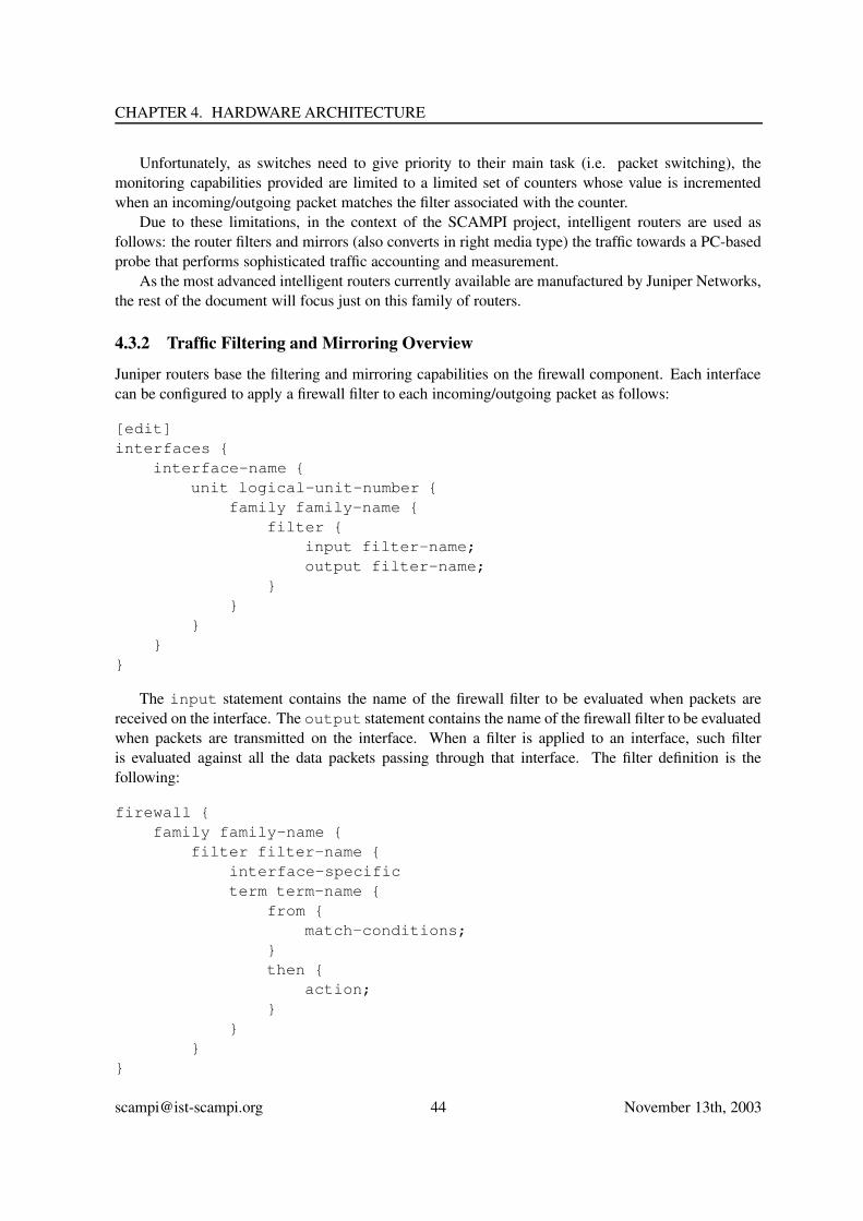
CHAPTER 4. HARDWARE ARCHITECTURE
Unfortunately, as switches need to give priority to their main task (i.e. packet switching), themonitoring capabilities provided are limited to a limited set of counters whose value is incrementedwhen an incoming/outgoing packet matches the filter associated with the counter.
Due to these limitations, in the context of the SCAMPI project, intelligent routers are used asfollows: the router filters and mirrors (also converts in right media type) the traffic towards a PC-basedprobe that performs sophisticated traffic accounting and measurement.
As the most advanced intelligent routers currently available are manufactured by Juniper Networks,the rest of the document will focus just on this family of routers.
4.3.2 Traffic Filtering and Mirroring Overview
Juniper routers base the filtering and mirroring capabilities on the firewall component. Each interfacecan be configured to apply a firewall filter to each incoming/outgoing packet as follows:
[edit]interfaces {
interface-name {unit logical-unit-number {
family family-name {filter {
input filter-name;output filter-name;
}}
}}
}
The input statement contains the name of the firewall filter to be evaluated when packets arereceived on the interface. The output statement contains the name of the firewall filter to be evaluatedwhen packets are transmitted on the interface. When a filter is applied to an interface, such filteris evaluated against all the data packets passing through that interface. The filter definition is thefollowing:
firewall {family family-name {
filter filter-name {interface-specificterm term-name {
from {match-conditions;
}then {
action;}
}}
}
[email protected] 44 November 13th, 2003

4.3. INTELLIGENT ROUTERS
The family-name statement can be set to inet for IPv4 and inet6 for IPv6. The filter-nameis an alphanumeric name (e.g. spam-filter) that is used to identify the filter in the previous interfacestatement. Each firewall filter consists of one or more terms. A term defines a filter statement thatis evaluated in the order in which are specified in the configuration. The from statement specifiesthe match conditions. The then statement specifies the action to perfom in case of match. Matchconditions include (but are not limited to):
• source/destination port
• source/destination IP address
• packet type/protocol/lenght
• ICMP type/code
• VLAN id
• TCP flags
• fragments (IPv4 only)
• next-header and traffic-class (IPv6 only).
Action conditions include (but are not limited to):
• accept
• discard
• reject
• count
• logical
• sample
Among the above actions, the two most important actions are:
count, that allows packet to be counted into the Juniper Firewall MIB, in a variable named filter-name,accessible via SNMP.
sample, that allows packets to be sent either to destination or to a mirror interface with/without thespecified sample rate.
A simple filter definition for mirroring/sampling broadcast traffic is the following:
firewall {family inet {
filter broadcast-access-control {from {
protocol udp;}then {
[email protected] 45 November 13th, 2003

CHAPTER 4. HARDWARE ARCHITECTURE
sample;}
}}
}
filter broadcast-access-control {term dest-broadcast {
from {destination-address {
255.255.255.255/32;}
}then {
accept;}
}}
4.3.3 Configuring Traffic Filtering and Mirroring
The configuration of traffic filtering and mirroring is usually performed via command line. Howeverin the context of SCAMPI this means of configuration is not really effective as those facilities are notconfigured once by a network administrator but rather by applications at runtime via the MAPI API.
In order to dynamically (re)configure the router, the best solution is to make mapid communicate inJUNOScript, an Extensible Markup Language (XML) application that Juniper Networks routing plat-forms used to exchange information with client applications. The JUNOScript API is a programmaticinterface that simplifies the development of applications or libraries that need to interact with the routerconfiguration. A basic JUNOScript session works as follows:
• The client application establishes a connection to the JUNOScript server running into the router,and opens the JUNOScript session.
• The JUNOScript server and client application exchange initialization tags, used to determine ifthey are using compatible versions of the routing software and the JUNOScript API.
• The client application sends one or more requests to the JUNOScript server and parses its re-sponses.
• The client application closes the JUNOScript session and the connection to the JUNOScriptserver.
• The JUNOScript API can be accessed from both C and Perl. Months ago the SCAMPI con-sortium has released a JUNOScript-enabled libpcap in order to demonstrate the feasibility ofthis approach. Based on this experience, the MAPI may also take advantage of JUNOScript fortransparently setting filters and configuring mirroring into the Juniper router.
[email protected] 46 November 13th, 2003

4.4. THE IXP1200 NETWORK PROCESSOR
4.4 The IXP1200 network processor
Like the SCAMPI Combo6 card, the Intel IXP network processors provide a platform that is capable ofprocessing data at a very early stage, before the data hits the PCI bus. A design for supporting MAPIon an IXP1200 is described in this section. The IXP1200 contains a single StrongARM processor(running Linux) and 6 microengines (running no operating system whatsoever). Figure 4.7 shows themain components of an architecture where a number of IXP1200 boards are plugged into the PCIbackplane of a host.
Figure 4.7: Main components of the IXP1200
A general-purpose processor on a host is connected to one or more IXP1200 evaluation boardsplugged into the PC’s PCI slots. Each of the boards contains a single IXP1200, on-board DRAM andSRAM (256MB and 8MB respectively) and two Gigabit Ethernet ports. The board drawn in Figure 4.7is based on the Radisys ENP-2506 IXP1200 board.
The IXP1200 itself contains a two-level processing hierarchy, consisting of a StrongARM controlprocessor and six independent RISC processors, known as microengines (MEs). On the IXP, the Stron-gARM runs the Linux operating system, while the MEs do not run any operating system. Each MEsupports 4 hardware contexts that have their own PCs and register sets (allowing it to switch betweencontexts at zero cycle overhead). Each ME runs its own code from a small (1K) instruction store.
MEs control the transfer of network packets to SDRAM in the following way. Ethernet frames arereceived at the MACs and transferred over the proprietary IX bus to an IXP buffer in 64 byte chunks,known as mpackets. From these buffers (which Intel has called RFIFOs, even though they are not realFIFOs at all) the mpackets can be transferred to SDRAM. MEs can subsequently read the packet datafrom SDRAM in their registers in order to process it.
[email protected] 47 November 13th, 2003

CHAPTER 4. HARDWARE ARCHITECTURE
4.4.1 APIs
When the IXP is used for implementing the MAPI, code will need to be provided in all levels of theprocessing hierarchy, sketched in Figure 4.7: on the MEs, on the StrongARM (Linux kernel), and onthe host processor (both kernel and userspace). The following components can be distinguished:
mapiIXPdrv: this module provides functions that support MAPI more or less directly (e.g. mapidrv create flow,mapidrv_aply_function, etc.).
IXPlib: this is the library that provides all functions needed for mapiIXPdrv functions to be imple-mented (e.g. ixp1200_get_next_packet,ixp1200_apply_function, etc.).
IXPdrv: the kernel driver for the IXP. It provides all the functions that are needed to implement IX-Plib, including the implementation of memory mapping the memroy of the IXP board to theapplication, etc.
IXP: the code on the network processor itself. It consists of code on the StrongARM and code on theMEs, responsible for receiving the packets and processing them.
Most relevant for a systems programmer implementing the MAPI is the API exported by IXPlib.Here the following functions are provided:
• int ixp1200_open (char *devname)opens the IXP1200 device (returns file descriptor);
• int ixp1200_close (int fd)closes the IXP1200 devive;
• flow_t ixp1200_create_flow (int fd, mode m): create all state needed for aflow of MAPI mode RAW, COOKED, or HIERARCHICAL(returns flow descriptor);
• int ixp1200_close_flow (flow_t f)destroy all state associated with a flow;
• ixp1200_apply_function (flow_t f, function func, ...)add a packet processing function to the linear list of functions associated with this flow;
• ixp1200_remove_function (flow_t f, function func, ...)remove a packet processing function to the linear list of functions associated with this flow;
• int ixp1200_connect (flow_t f)instantiate a flow (perform all admission checks, if relevant);
• int ixp1200_activate (flow_t f)start/activate a flow;
• int ixp1200_pause (flow_t f)stop/pause a flow;
• int ixp1200_loop (flow_t f, int count, callback_t callback)register a callback;
[email protected] 48 November 13th, 2003

4.5. COMMODITY INTERFACES
Regular Network I/F
Hostprocessor Memory
BUS
To the Internet
Monitored linkSplitter
SCAMPI monitoring based on commodity adapters
Commodity PC
Regular Network I/Fin promiscuous
mode
Figure 4.8: SCAMPI monitoring system based on commodity-only network interfaces.
• packet *ixp1200_get_next_packet(flow_t f, int copy)get the next packet from the buffer (either by copy or by reference);
• management_info *ixp1200_get_management_info (int info_type)get information about the status of the monitoring hardware (the components of the IXP1200).
• int ixp1200_advance_read_position(flow_t f, int offset)Indicate to the IXP that the flow has processed offset packets, so the buffer space may bereused;
• function_mem_list_t ixp1200_get_function_mem(flow_t f)for each function applied to the flow, get a pointer to memory to be used for direct communicationwith this function (if applicable). For example, a packet counter may provide a pointer to read-only memory where the counters are updated, while a NETFLOW function may provide memorywhere flow records are stored.
• int ixp1200_memcpy_atomic(flow_t f, void *dst, void *src, int len)Atocmically copy a chunk of memory from or to memory areas belonging to functions;
4.5 Commodity Interfaces
4.5.1 Commodity Interfaces in Promiscuous Mode
Although special purpose hardware based on network processors, DAG cards, the combo6 board, andintelligent routers can be used for network monitoring, commodity networks adapters provide a simple
[email protected] 49 November 13th, 2003

CHAPTER 4. HARDWARE ARCHITECTURE
and inexpensive alternative. For example, several commodity network adapters can be set to functionin a special mode operation called “promiscuous mode”. In this mode, the adapter receives all packetsthat travel through the network (not only packets destined for that particular adapter as is the case ina regular mode of operation). This (promiscuous) mode of operation has been traditionally used tomonitor shared communication media, like shared Ethernet, token ring, and wireless media. However,this promiscuous mode can also be used to monitor any network link, independently of whether it isshared or not. This can be done by capturing a mirror of the link’s traffic (through an optical trafficsplitter or a mirroring port within a switch) and send this mirror to a (commodity) network interfacewhich has been set in promiscuous mode (as shown in Figure 4.8). Commodity network interfaces putin promiscuous mode is the simplest form of network monitoring hardware. Although financially ap-pealing, this solution suffers in performance, because the network adapter (through the optical splitter)receives and forwards to the host processor all the network traffic, even in the case where most of itis not needed. Thus, the host processor is burdened with the task of processing all traffic and filteringthe interesting subsets of it. In addition, the host processor needs to copy all packets from the adaptorto the main memory, and may need to process them using some high-level protocol (like IP or evenTCP/IP). To make matters worse, most commodity adaptors interrupt the host processor for each andevery packet they receive. Thus, when receiving small packets in high-speed links host processors areoverwhelmed with interrupt processing, having left little, if any, capacity to do network monitoring.
4.5.2 The commodity adapter API
Commodity adapters put in promiscuous mode do not have (or at least do not export) any extra process-ing capabilities that can be capitalized by MAPI implementations. Therefore, a commodity adapter putin promiscuous mode can do nothing more than receive packets and deliver them to the applicationsabove. Therefore MAPI implementations on top of commodity adapters can be implemented on top ofthe pcap library [16]. The functions exported by pcap that can be used to implement MAPI are:
pcap open live is used to obtain a packet capture descriptor and start capturing packets passing throughthe network
pcap set filter is used to specify a filter program: only packets that match the filter are eventuallydelivered to the user application.
pcap next returns a pointer to the next packet
All the rest of the functionality provided by MAPI, including function application, filtering, etc.will be provided completely in software.
[email protected] 50 November 13th, 2003

Chapter 5
Software Structure
The overall software architecture of the SCAMPI system is shown in figure 5.1. We see that the centralpart of the SCAMPI software architecture is the MAPI daemon: mapid. As shown in figure 5.1,the daemon, that runs in user space, communicates with the monitoring applications on top, and withthe operating system kernel below. The kernel, in turn communicates with the underlying hardwaremonitoring system.
5.1 The MAPI daemon
The MAPI daemon (mapid) is responsible for implementing the MAPI functionality. On the one hand,the deamon receives monitoring requests from several different applications, and on the other hand, thedaemon receives a stream of network packets from the undeerlying monitoring system (whether theoperating system kernel or the hardware). mapid is responsible for applying the monitoring requestsof the applications on the incoming stream of packets, for caclulating the requested statistics, and fordelivering the appropriate network packets to the relevant monitoring applications. We can picture themapid as a sophisticated de-multiplexer. It receives a stream of packets from the underlying system,processes the packets, discards some of them, and divides the remaining into several streams: eachstream destined to a different application.
5.1.1 mapidcom
mapidcom is the module that handles all the communication with the user applications. mapidcomconsists of an infinite loop that receives and processes requests from applications. Each request consistsconsits of a structure as follows:
struct mapiipcbuf {mapiipcMsg cmd;mapiFunction function;mapiFunctArg fargs[FUNCTARGS_BUF_SIZE]; // holds function argumentschar str[128]; // only for dev parameter of create_flow()
};
The structure contains all the necessary arguments to implement this request:
• cmd contains the request sent by the application to the mapid. Such requests are:
51

CHAPTER 5. SOFTWARE STRUCTURE
mapid
mapicombo6drv mapidagdrv
resourcectrl
mapinicdrv
mapidcom
scampilib
mapidlib
libpcapdaglib
Hardware
combo6 NICdag
kernel
combo6drvdagdrv nicdrv
application1
mapi
application2
mapi
Figure 5.1: The main modules of the MAPI monitoring system.
[email protected] 52 November 13th, 2003

5.1. THE MAPI DAEMON
CREATE_FLOWAPPLY_FUNCTIONREAD_RESULTCONNECTCLOSE_FLOWREAD_ERROR
For example the CREATE FLOW request creates a flow, the APPLY FUNCTION request appliesa function to it, and so on.
• str is the name of the monitoring device that will provide the packets to the network flow.
• function is the function that must be invoked on each packet of the network flow. The sup-ported functions are listed in appendix B.
• fargs[FUNCTARGS BUF SIZE] is a buffer that is being used to keep the arguments of thefunction being invoked.
• fd is the network flow descriptor.
5.1.2 Admission Control and Resource Costs
Admission control for MAPI has been designed as an independent module. It is a daemon process,known as authd, that runs standalone and uses shared memory IPC to communicate with mapid. It isresponsible for authenticating a user, as well as checking his/her credentials against the specificationsof a flow before connecting the flow to the system. In other words, if the application does not havethe appropriate privileges (credentials) to create a flow with these characteristics (filters, functionsapplied to it, etc.) it will be rejected. At the same time the amount of resources needed by a flow iscalculated and returned to mapid to determine their availability in the system. If not enough resourcesare available, the flow may still be rejected.
5.1.2.1 Admission Control Inputs
The information required for the authentication of a user include: his/her public key, a positive integernumber, and the same number encrypted with the user’s private key. This information is enough toassure that the user actually holds the public/private key pair of the public key used for identification(and hence, that users are who they say they are). For convenience, we can use the flow id (the filedescriptor) for this purpose.
The information required to authorize a flow that a user wants to connect include:
• the user’s public key;
• the user’s credentials (using the Keynote format [3]);
• the device with which the flow is associated;
• a list of the functions that are going to be applied to the flow (e.g. filters, counters, samplers,etc.).
[email protected] 53 November 13th, 2003

CHAPTER 5. SOFTWARE STRUCTURE
The device name and the list of the applied functions are used to generate assertions about theflow. Such assertions cover for example the type of the functions applied, the number of instancesof a specific function type, the position of the instances (in the linear list of applied functions) andthe arguments passed to them. For example, one may want to specify that a user is allowed to applya string search function, but no more than one and only if the string search function is applied aftera sampling function that grabs no more than 50% of the packets. The assertions and credentials areprocessed using Keynote to check whether there are no conflicts between the user’s credentials and theflows specifications.
An example of the sort of assertions that may be expressed in the Keynote credentials with respectto this is shown below. In the credential shown here, an authorizer grants a licensee (both identified bytheir public keys) the right to apply certain functions to their flow, subject to specific conditions. Theseconditions specify that the flow request is only valid in application domain MAPI, if the device that theflow is created for is one of eth0..eth9., if the flow has fewer than 2 packet counters, fewer than 2string search operations and at least one sampler (with a specific first parameter), where the samplershould be applied before the string search (presumably to prevent a computationally intensive functionlike string search from being applied to every packet). The credential is signed by the authorizer, e.g.the system administrator, or someone to whom the system administrator has delegated part of his/herpowers (via another set of credentials).
KeyNote-Version: 2Comment: Within the application domain MAPI, the authorizer
grants the licensee(s) the right to use a set offunctions under specific conditions (e.g. regardingthe number of occurrences and the order in which thesefunctions are applied). Note: keys and signatures areabbreviated for clarity.
Authorizer: "rsa-base64:MIGJAoGBAMbP4gS2x72ZF1PrnN//VEXfkYMtb="Licensees: "rsa-base64:MIGJAoGBAKmynDiwN1tAKd6sGTHulfuyOoApl="Conditions: app_domain == "MAPI" && device_name ˜= "eth[0-9]" &&
@$("PKT_COUNTER.num") < 2 && @$("STR_SEARCH.num") < 2 &&@$("PKT_SAMPLER.num") > 0 && &$("PKT_SAMPLER.param.1") < 0.5 &&@$("PKT_SAMPLER.first") < @$("STR_SEARCH.first") < 2 &&-> "true";
Signature: "sig-rsa-sha1-base64:i3zsmSamFnCs7SegUIPgJ6921In+U="
While this is a fairly trivial sort of access condition, it shows the power that such admission controloffers. Not only does it guard against unauthorized access, it also helps in preventing misconfiguration.If needed, much more complex conditions can be specified, e.g. concerning the parameters of functions(including maximum and minimum values), their absolute and relative positions in the list of functionsto be applied, etc.
Finally for a flow to be allowed to connect, it must be checked whether the system has the necessaryresources available. Authd holds the responsibility for calculating the amount of resources needed bya flow. The amount of resources needed by a flow is determined by using the list of applied functions.Each applied function imposes a cost in terms of resources needed by the flow to be connected. Thecost of each function is going to be dependent on its type as well as its arguments, and it is measuredin terms of processing time, memory consumption, etc. Each function type is associated with an arith-metical formula that can also include the function’s arguments. This formula, along with the function’sarguments, is passed to a cost calculation function to provide the cost of applying the function. The
[email protected] 54 November 13th, 2003

5.1. THE MAPI DAEMON
formula consists of a simple expression in a subset of the language that was defined for FFPF 1 (itincludes the common arithmetic operations and refers to a function and its parameters, e.g. memoryusage equals x · param1 + y · (param2 + param3)). The sum of the costs of all applied functionsconsists of the required resources of a flow. Not specifying the cost formula will be interpreted as zeroresource consumption. In other words, a site that does not require such elaborate resource control maysimply leave these entries blank.
5.1.2.2 Authd and Mapid communication
Authd and mapid exchange information through a shared memory segment. The functions used toaccess shared memory are listed in Appendix F. Synchronization of the two processes is possible usinga semaphore set. A typical request to authd would include the steps described below.
Steps for mapid:
• lock the shared memory segment;
• store the request data to the shared memory segment;
• signal authd;
• wait to receive a signal from authd;
• get the results from the shared memory segment;
• unlock the shared memory segment.
Steps for authd:
• wait to receive signal from authd;
• process the data in shared memory and place results;
• signal mapid.
The functions used to manage the semaphore set and perform the actions shown above are listed inthe appendix F.
All the information that need to be passed to admission control are included in the scampi_authdata-type that is described in the appendix F. The results returned by authd include an authorizationvalue and the amount of resources needed by the flow. These are included in the flow_auth data-type described also in the appendix. Mapid holds responsibility to check if the amount of availableresources is adequate to connect the flow.
5.1.3 The libscampi
The typical MAPI implementor usually interacts with the libscampi library instead of interactingdirectly with the combo6 driver or the card itself. The libscampi library exports the followingfunctions:
1See appendix F.
[email protected] 55 November 13th, 2003

CHAPTER 5. SOFTWARE STRUCTURE
int scampiOpen(char *name);int scampiClose(int fd);int scampiSetOption(int fd, int option, void * value);int scampiGetOption(int fd, int option, void * value);unsigned char * scampiGetNextPacket(int fd, int * size);/** Returns pointer to specified number of new packets and locks these packets* in the circular buffer - not yet implemented.*/
unsigned char * scampiGetNextOffset(int fd);* Unlocks any packets locked on behalf of this application** Input:* fd - file descriptor*/
void scampiUnlockPackets(int fd);
A typical sequence of actions performed in the software that uses libscampi is as follows:
1. A program opens a SCAMPI device (this simple call hides all initialization including memorymapping):
int fd=scampiOpen("/dev/scampi/0");
2. Then (or anytime later), a program can set or get SCAMPI device options:
scampiSetOption(fd, option1, &value1);scampiSetOption(fd, option2, &value2);
The following options are supported (but not all of them are necessarily implemented by earlySCAMPI driver and libscampi versions);
• SCAMPI LIB FILTER - sets packet filter
• SCAMPI LIB SAMPLER - sets packet sampler
• SCAMPI LIB STATMAP - sets bitmask for statistic counters
• SCAMPI LIB STATISTICS - gets statistics
• SCAMPI LIB FUNCTIONALITY - gets functionality supported by this adapter
3. Next, packets can be read:
int size;char *packet=scampiGetNextPacket(fd, &size);
4. Finally, a program should unlock the last packet and close the SCAMPI device:
scampiUnlockPackets(fd);scampiClose(fd);
[email protected] 56 November 13th, 2003

5.1. THE MAPI DAEMON
5.1.4 The drivers
Each monitoring devic is supported by device-specific user-level code which is called “the driver” forthis device 2 Figure 5.1 shows three such drivers: one for the combo6 card (mapicomb06drv), one forthe DAG card (mapidagdr), and one for commodity interfaces put in promiscious mode (mapinicdrv).Each driver implements the following functions:
//create a new flowmapi_drv_create_flow(char * dev, int fd)// closes an old flowmapidrv_close_flow (char *dev, int fd)
//connects to a flow - the flow starts receiving packetsmapidvr_connect (int fd)
// applies function with fargs to all packets of a flowmapidrv_apply_function (int fd, mapiFunction function, mapiFunctArg *fargs)
// this is the main function of the driver:// it reads and processes one-packet-at-a-timemapidrv_proc_loop()// processes one packetmapidrv_process_pkt(char * packet, struct mapid_pkthdr * pkt head)
//reads the results of funcction fid fot network flow fd// the results are being returned into the buffer void * resultmapidrv_read_results(int fd, int fid, void * result)mapidrv_probe (char *dev, int fd)
//returns the latest error numbermapidrv_get_errno()
5.1.5 mapidlib
The mapidlib is a library that contains a variety of functions for implementing mapid, and espe-cially the functions that are independent of the monitoring hardware or that can be used by more thanone drivers. Such functions include:
• Functions that handle network flows
// adds a new flow and to the list of known flowsint mapid_add_flow(int fd);
//connects to a flow and enables the reception of packets
2Note that these drivers are distinct entities from the device drivers of the operating system kernel.
[email protected] 57 November 13th, 2003

CHAPTER 5. SOFTWARE STRUCTURE
int mapid_connect(int fd);
int mapid_close_flow(int fd);
//read results from a flowvoid* mapid_read_results(int fd, int fid,
int copy);// adds a new function to be applied to all packets of a flowint mapid_apply_function(int fd,
mapiFunction function,void* fptr,mapiFunctArg *fargs);
// processes a single packet by applying all functions to itvoid mapid_process_pkt(const unsigned char* pkt,
struct mapid_pkthdr* pkt_head);
• Functions applied to each packet
// filterfunction_bpf_filter(struct mapid_function *funct,
const unsigned char* pkt,const struct mapid_pkthdr *pkthdr)
// count the bytes of all packets in a flowfunction_bytecounter(struct mapid_function *funct,
const unsigned char* pkt,const struct mapid_pkthdr *pkthdr)
// count packetsfunction_counter(struct mapid_function *funct,
const unsigned char* pkt,const struct mapid_pkthdr *pkthdr)
// string searchfunction_str_search (struct mapid_function *funct,
const unsigned char* pkt,const struct mapid_pkthdr *pkthdr)
//dumps packets into a buffer for eventual delivery to the applicationsfunction_to_buffer(struct mapid_function *funct,
const unsigned char* pkt,const struct mapid_pkthdr *pkthdr)
[email protected] 58 November 13th, 2003

5.2. KERNEL-BASED SOFTWARE
5.2 Kernel-based Software
A portion of the MAPI software runs inside the operating system kernel as device drivers. Devicedrivers for commodity NICS and for the DAG cards were provided by their manufacturers. However,the driver for the combo6 monitoring card was written by members of the SCAMPI consortium.
5.2.1 The combo6 driver
The next upper layer sitting just above the Combo6 driver exports to the SCAMPI library a set of ioctl()calls and memory mapped regions.
5.2.1.1 ioctl() calls
The following set of ioctl() calls is available:
• SCAMPI IOCTL VERSION - read int type, gets driver version
• SCAMPI IOCTL APP NUMBER - read int type, gets assigned application number
• SCAMPI IOCTL INTERFACES - read int type, gets number of physical interfaces on thisSCAMPI adapter
• SCAMPI IOCTL GET INTERFACE - write/read struct scampi ioctl get interfacetype, gets description of a given physical interface
• SCAMPI IOCTL SUBSCRIBE INTERFACE - write struct scampi ioctl subscribe interfacetype, subscribes to a given physical interface
• SCAMPI IOCTL UNSUBSCRIBE INTERFACE - write struct scampi ioctl subscribe interfacetype, unsubscribes from a given physical interface
• SCAMPI IOCTL RBUFFER - read struct scampi ioctl rbuffer type, gets size of packetcontent ring buffer
• SCAMPI IOCTL START - no argument, starts packet capture
• SCAMPI IOCTL STOP - no argument, stops packet capture
• SCAMPI IOCTL LOCK NEXT - no argument, locks next packet to be read from a memorymapped region
• SCAMPI IOCTL LOCK MULTI - write u int32 t type, locks up to given number of packetsto be read from a memory mapped region
• SCAMPI IOCTL UNLOCK - no argument, unlocks all packets
• SCAMPI IOCTL GET STATS - read struct scampi ioctl stats type, gets statisticsand clears all counters
The relevant section of the header file will be as follows:
[email protected] 59 November 13th, 2003

CHAPTER 5. SOFTWARE STRUCTURE
#define SCAMPI_MAX_FILTER_HEADERS 256#define SCAMPI_MAX_FILTER_PAYLOAD 16
/* Phase I adapter only supports headers[] field */struct scampi_ioctl_set_filter {/* tcpdump syntax */char headers[SCAMPI_MAX_FILTER_HEADERS];/* 0 = none, 1 = deterministic, 2 = probabilistic */u_int8_t sampler_type;u_int32_t sampler_rate;char (*payload)[SCAMPI_MAX_FILTER_PAYLOAD];};
/** ioctl definition*/
/** Phase I adapter: can be used only once* Phase II adapter: each application can have its own filter*/
#define SCAMPI_IOCTL_SET_FILTER _IOW(’X’, 0x50, struct scampi_ioctl_set_filter)
5.2.1.2 Memory mapped regions
The following memory regions can be mapped from the Combo6 device to upper layers. We intention-ally do not specify numerical values of memory addresses, as they can change with different adapterreleases. Programmers should use the symbolic constants instead.
• SCAMPI MMAP OFFSET PKT - mmap offset for packet contents
• SCAMPI MMAP OFFSET PKTDSC - mmap offset for packet descriptors(struct scampi mmap packet descriptor)
• SCAMPI MMAP OFFSET LOCK - mmap offset for packet locks(struct scampi mmap app lock)
• SCAMPI MMAP OFFSET ISTATS - mmap offset for packet statistics per interface(struct scampi mmap packet istats)
• SCAMPI MMAP OFFSET STATUS - mmap offset for packet status(struct scampi mmap packet status)
5.2.1.3 Using Combo6 driver
A typical sequence of actions performed in the software that uses the Combo6 driver is as follows.These actions are normally performed within libscampi and an application that uses libscampi does notneed to care about these low-level details.
[email protected] 60 November 13th, 2003

5.2. KERNEL-BASED SOFTWARE
1. libscampi opens the Combo6 adapter special device file /dev/scampi/n, where n is 0 for thefirst adapter and obtains a Combo6 driver handle:
int fd=open(SCAMPI_DEVICE, O_RDWR);
2. The Combo6 driver version, an assigned application number and the number of physical networkinterfaces present on the Combo6 are determined: adapter:
int version, appNumber, ifNo;ioctl(fd, SCAMPI_IOCTL_VERSION, &version);ioctl(fd, SCAMPI_IOCTL_APP_NUMBER, &appNumber);ioctl(fd, SCAMPI_IOCTL_INTERFACES, &ifNo);
Selected network interfaces are subscribed to:
3. /* Subscribe to first interface */struct ioctl_subscribe_interface ifSub;ifSub.if_index[0]=1;ifSub.if_index[1]=0xFF;ioctl(fd, SCAMPI_IOCTL_SUBSCRIBE_INTERFACE, &ifSub);
The size of packet content ring buffer is determined:
4. struct scampi_ioctl_rbuffer rbufferSize;ioctl(fd, SCAMPI_IOCTL_RBUFFER, &rbufferSize);
5. The necessary memory regions are mapped, that is at least the packet content ring buffer, packetdescriptors buffer and packet locks:
/* Map packet contents to user space */unsigned char *rbuffer;rbuffer=(unsigned char *) mmap(NULL, (size_t) rbufferSize.dma_size,
PROT_READ, MAP_SHARED, fd, SCAMPI_MMAP_OFFSET_PKT);
/* Map packet descriptors to userspace */tPacketDesc *rbufferDesc;rbufferDesc=(tPacketDesc *) mmap(NULL,
(size_t) (rbufferSize.packets * sizeof(tPacketDesc)),PROT_READ, MAP_SHARED, fd, SCAMPI_MMAP_OFFSET_PKTDSC);
/* Map packet locks */struct scampi_mmap_app_lock *locks;locks=(struct scampi_mmap_app_lock *) mmap(NULL,
(size_t) (sizeof(struct scampi_mmap_app_lock)),PROT_READ, MAP_SHARED, fd, SCAMPI_MMAP_OFFSET_LOCK);
6. The packet capture is started:
[email protected] 61 November 13th, 2003

CHAPTER 5. SOFTWARE STRUCTURE
ioctl(fd, SCAMPI_IOCTL_START, &rbuffer);
A corresponding ioctl() call SCAMPI IOCTL STOP can be used to suspend packet capture whenapplication cannot catch up with the volume of packets received. Note that other applications mightstill be running after one application executes this call and thus packets can be still overwritten in thering buffer even if the application stops the capturing. To get a descriptor of the next packet in fifo fora given application and lock this packet, ioctl() call SCAMPI IOCTL LOCK NEXT is used. This callalso automatically unlocks the previous packet.
At the end of communication, the remaining lock should be released with ioctl() call SCAMPI IOCTL UNLOCKand the file descriptor should be closed. A typical sequence use after initialisation (opening device, sub-scribing to interfaces and mapping memory regions): SCAMPI IOCTL LOCK NEXT, SCAMPI IOCTL LOCK NEXT,..., SCAMPI IOCTL UNLOCK. Access to unlocked areas is permitted, but not very useful, becausethe driver or hardware might overwrite data at any time.
Statistics can be obtained via a mmaped area or using ioctl() call SCAMPI IOCTL GET STATS,which also clears all counters.
For loading packet filters, a daemon which communicates via another character device (/dev/combosix/n)will be available. This daemon will communicate with libscampi using sockets or IPC shared memory.It will merge requests from all applications and write the final filter and specific setup to the hardware.
5.2.1.4 Low-level access
The following low-level ioctl() calls are also available:
• COMBO6 READ - reads part of card’s address space into the supplied buffer. Argument shouldbe a pointer to struct combo6 ioc arg
• COMBO6 WRITE - writes part of card’s address space from the supplied buffer. Argument shouldbe a pointer to a struct combo6 ioc arg
The combo6 ioc arg structure is defined in combo6io.h file.
5.3 SNMP
5.3.1 Management functions
The SCAMPI platform will be a complex system that will need some sort of management. The MAPImanagement functions will provide applications information about the internal workings of MAPI aswell as usage statistics.
The following management functions have been defined:
mapi get mngt var returns simple management variables like the number of active users, numberof active flows etc.
mapi set mngt var sets the value of a management variable
mapi get device info list returns a linked list of information about devices. The followingstructure is used:
[email protected] 62 November 13th, 2003

5.3. SNMP
typedef struct mapiDeviceInfoList {unsigned index; //index of devicechar *name; //Name of devicechar *description; //Description of devicechar *alias; //User defined alias for the deviceunsigned numInterfaces; //Number of interfaces on deviceint gpsSync; //Positive value if device is synchronized with GPS receiverstruct mapiDeviceInfoList *next; //Pointer to next record
} mapiDeviceInfoList t;
mapi get interface info list returns a linked list of information about interfaces. The fol-lowing structure is used:
typedef struct mapiInterfaceInfoList {unsigned index; //Interface indexunsigned devIndex; //Index of device this interface belongs tounsigned ifType; //Type of interfaceunsigned ifSpeed; //Speed of interfacechar *alias; //User defined alias of the interfaceenum mapiIfStatus ifStatus; //Status of interfaceunsigned long pkts; //Total captured packetsunsigned long octets; //Total captured octetsunsigned long droppedPkts; //Total dropped packetsstruct mapiInterfaceInfoList *next; //Pointer to next record
} mapiInterfaceInfoList t;
mapi get flow info list returns a linked list of information about active and recently closedflows. The following structure is used:
typedef struct mapiFlowInfoList {unsigned flowIndex; //Flow descriptor of the flowunsigned UID; //UID of the process that owns the flowunsigned dev; //Device this flow capture packets fromunsigned interface; //Interface on the device this flow
//captures packets fromunsigned long pkts; //Total captured packetsunsigned long octets; //Total captured octetsunsigned long droppedPkts; //Total dropped packetsunsigned long long start; //Timestamp of when the flow
//was createdunsigned long long stop; //Timestamp of when the flow
//was closedint gpsSync; //A positive value indicates proper GPS
//synchronization during the lifetime of the flowstruct mapiFlowInfoList *next; //Pointer to next record
} mapiFlowInfoList t;
An important aspect of the implementation of the management functions is that they should not have anegative impact on the performance of the system. Management functions are therefore not consideredhigh priority.
[email protected] 63 November 13th, 2003

CHAPTER 5. SOFTWARE STRUCTURE
It is the MAPI drivers that keep track of the management information and increments the necessarycounters as it receives packets from the hardware adapter.
When a user request some management information through the management functions, an IPCmessage is sent from the application to the MAPId. The mapidcom module receives the message andcollect the necessary information from the MAPI drivers before returning the answer to the application.
5.3.2 SNMP Access
A SCAMPI MIB will be developed so that the MAPI management functions can be accessed throughSNMP. The SCAMPI MIB will be implemented using NET-SNMP[20]. NET-SNMP is a collection ofvarious tools relating to SNMP released under a BSD like licensing. Some of the components in thistool are:
• Extensible agent - an SNMP agent that provides the necessary mechanisms for easy extensibility.New MIB modules can be added and removed dynamically without restarting the agent.
• SNMP library - a relatively easy to use SNMP library that developers can use to implement newMIBs and SNMP utilities.
• tools to request or set information from SNMP agents
• tools to generate and handle SNMP traps
The SCAMPI MIB will be implemented in C as an AgentX sub-agent.The managed objects available in the SCAMPI MIB will be organized into four main groups as
shown in figure 5.2. A full definition of the MIB is included in Appendix G.1.
5.3.2.1 scampiDevices
This group provides information about each SCAMPI adapter and its interfaces that are availablethrough MAPI to do measurements with. It is organized into two tables, one for devices and onefor interfaces on devices.
5.3.2.1.1 scampiDeviceTable This table provides various information about devices.
scampiDeviceIndex A unique value, greater than zero, for each device available for monitoringthrough MAPI.
scampiDeviceName A textual string containing the name of the device. The name should uniquelyidentify the device in the host system. An example of a device name is ’/dev/eth1’
scampiDeviceDescr A textual string containing information about the device. The string shouldinclude the name of the manufacturer, the product name and the version of the devicehardware/software.
scampiDeviceAlias This object is an ’alias’ name for the device as specified by a network man-ager, and provides a non-volatile ’handle’ for the device.
scampiDeviceIfNum An integer representing the number of interfaces on the device.
scampiDeviceGPSSync A boolean value used for signaling GPS time synchronization problems.
[email protected] 64 November 13th, 2003

5.3.SN
MP
scampiMIB scampiMIBObjects(1)
scampiDeviceIfTable(1) scampiDeviceIfEntry(1)
scampiDevIfIndex(1)
scampiDevIfAlias(5)
scampiDevIfStatus(6)scampiDevIfPkts(7)scampiDevIfOctets(8)scampiDevIfDroppedPkts(9)scampiDevIfCounterDiscontinuityTime(10)
scampiFlows(3)scampiFlowCfgMaxHistLength(1)scampiFlowCfgMaxTime(2)
scampiFlowTable(3) scampiFlowEntry(1)
scampiFlowUID(2)scampiFlowIndex(1)
scampiFlowIfIndex(3)
scampiFlowPkts(5)scampiFlowOctets(5)scampiFlowDroppedPkts(6)
scampiFlowStart(8)scampiFlowStop(9)
scampiMapi(2)
scampiMapiUsers(1)scampiMapiFlows(2)scampiMapiFunctions(3)scampiMapiUserFunctions(4)
scampiMeasurements(4)
scampiMesCfgTable(1) scampiMesCfgEntry(1)
scampiMesCfgUID(1)scampiMesCfgIndex(2)scampiMesCfgIfIndex(3)scampiMesCfgIntervalSec(4)
scampiMesCfgMaxLength(6)scampiMesCfgActive(7)scampiMesCfgStorageType(8)scampiMesCfgStatus(9)
scampiMesTable(2) scampiMesEntry(2)
scampiMesUID(1)scampiMesIndex(2)scampiMesIntervalId(3)scampiMesStartSec(4)scampiMesStartFrac(5)scampiMesPkts(6)scampiMesOctets(7)
scampiDevices(1)
scampiDeviceTable(1) scampiDeviceEntry(1)
scampiDeviceIndex(1)scampiDeviceName(2)scampiDeviceDescr(3)scampiDeviceAlias(4)scampiDeviceIfNum(5)scampiDeviceGPSSync(6)
scampiDevIfDeviceIndex(2)scampiDevIfType(3)
scampiDevIfSpeed(4)
scampiFlowCondition(4)
scampiFlowGPSSync(7)
scampiMesCfgIntervalFrac(5)
Figure5.2:
SCA
MPIM
IB
scampi@
ist-scampi.org
65N
ovember
13th,2003

CHAPTER 5. SOFTWARE STRUCTURE
5.3.2.1.2 scampiDeviceIfTable This table provides various information about interfaces on de-vices.
scampiDevIfIndex A unique value, greater than zero, for each interface available for monitoringthrough MAPI.
scampiDevIfDeviceIndex A reference to scampiDeviceIndex identifying which device this in-terface belongs to.
scampiDevIfType The type of interface.
scampiDevIfSpeed The supported bandwidth of the interface in units of 1,000,000 bits per sec-ond.
scampiDevIfAlias This object is an ’alias’ name for the interface as specified by a network man-ager, and provides a non-volatile ’handle’ for the interface.
scampiDevIfStatus The current status of the interface. The status can be: active, ready, unavail-able, linkLost or unknown.
scampiDevIfPkts The total number of packets captured by the interface.
scampiDevIfOctets The total number of octets captured by the interface.
scampiDevIfDroppedPkts The total number of dropped packets during packet capture by theinterface.
scampiDevIfCounterDiscontinuityTime The value of sysUpTime on the most recent occasion at whichany one or more of this interface’s counters suffered a discontinuity.
5.3.2.2 MAPI group
This group provides general information about the MAPI resources.
scampiMapiUsers The total number of unique users that are currently using MAPI.
scanouMapiFlows The total number of active flows in MAPI.
scampiMapiFunctions The total number of predefined functions in MAPI that are currently inuse.
scampiMapiUserFunctions The total number of user defined functions registered with MAPIthat are currently in use.
5.3.2.3 Flow group
This group provides information about open flows in MAPI as well as a history of past flows.
scampiFlowMaxHistLength Specifies the maximum number of finished flows that are displayedin the scampiFlowTable.
scampiFlowMaxTime Specifies the maximum age in seconds of entries in scampiFlowTable. Thisis the number of seconds since scampiFlowStop.
[email protected] 66 November 13th, 2003

5.3. SNMP
5.3.2.3.1 scampiFlowTable This table provides information and statstics about flows that havebeen created through MAPI.
scampiFlowIndex A unique integer value used for identifying the flow.
scampiFlowUID The UID of the process that initiated this flow.
scampiFlowIfIndex The scampiIfIndex of the interface that the flow uses to capture packets.
scampiFlowPkts The total number of packets captured by the flow.
scampiFlowOctets The total number of octets captured by the flow.
scampiFlowDroppedPkts The total number of dropped packets during packet capture by the theflow.
scampiFlowGPSSync A boolean value that indicates GPS synchronization problems during thelifetime of the flow.
scampiFlowStart The sysUpTime of when the flow started.
scampiFlowStop The sysUpTime of when the flow finished. A value of 0 indicates that the flow isstill active.
5.3.2.4 Measurement group
The measurement groups provides detailed statistics about number of packets and bytes in a time inter-val, usually in the sub second domain.
5.3.2.4.1 scampiMesCfgTable This table is used for configuring measurement jobs.
scampiMesCfgUID The UID of the user who created and controls this measurement.
scampiMesCfgIndex The index of the measurement. Should be unique for the the for the corre-sponding scampimesCfgUID value.
scampiMesCfgIfIndex Reference to scampiDevIfIndex and specifies which interface that shouldbe used for measurements.
scampiMesCfgIntervalSec scampiCfgMesIntervalSec and scampiCfgMesIntervalFrac togetherform the time interval for measurements. scampiCfgMesIntervalSec specifies the numberof whole seconds of the interval
scampiMesCfgIntervalFrac scampiMesCfgIntervalSec and scampiCfgMesIntervalFrac togetherform the time interval for measurements. scampiMesStartFrac is the sub-second part of theinterval in units of 2ˆ-32 seconds.
scampiMesCfgMaxLength The maximum number of entries for this measurement in the scampiMesTable.
scampiMesCfgActive If set to 1 the measurement is active and results are stored in scampiMesTable.A value of 0 indicates that the measurement is is inactive and no results are put intoscampiMesTable.
[email protected] 67 November 13th, 2003

CHAPTER 5. SOFTWARE STRUCTURE
scampiMesCfgStorageType The storage type of this conceptual row.
scampiMesCfgRowStatus The status of this conceptual row.
5.3.2.4.2 scampiMesTable The results from measurement jobs defined in scampiMesCfgTable arestored in this table.
scampiMesUID The UID of the user who created and controls this measurement.
scampiMesIndex The index of the measurement.
scampiMesIntervalId A unique ID for the time interval.
scampiMesStartSec scampiMesStartSec and scampiMesStartFrac together form a timestamp forwhen the interval started. scampiMesStartSec contains number of second since midnightJanuary 1 1970.
scampiMesStartFrac scampiMesStartSec and scampiMesStartFrac together form a timestampfor when the interval started. scampiMesStartFrac is the sub-second part of the timestampin units of 2ˆ-32 seconds.
scampiMesPkts Total number of packets captured during the interval.
scampiMesOctets Total number of bytes captured during the interval
5.3.3 Using the SCAMPI MIB
Managers will use the scampiDevices and scampiMapi groups to monitor the status of a SCAMPIplatform. By polling the scampiDevices group at regular intervals, managers can detect problemswith network connections and GPS synchronization. The scampiDevIfDroppedPkts reports droppedpackets by an interface. Dropped packets will usually be a sign indicating that the SCAMPI platformis overloaded and is trying do to run too many monitoring jobs. However, since a SCAMPI platform isa normal PC other processes that are not related to SCAMPI can also cause CPU congestion resultingin dropped packets. By combining the counter of dropped packets with the usage statistics of MAPIfrom scampiMapi, a manager will usually be able to detect when the cause of dropped packets ismeasurement jobs.
The scampiFlows group can be used by managers to get a detailed overview of which users arerunning measurement jobs and who are using the SCAMPI platform the most. By polling this group atregular intervals, managers can generate a usage history of the SCAMPI platform.
The scampiMeasurement group is not related to monitoring the status of the SCAMPI platformbut is an SNMP interface to MAPI for counting packets and octets at user defined intervals. A usercan set up one or more measurement jobs by creating rows in the scampiMesCfgTable. A row in thistable specifies which interfaces that should be monitored and the length of the interval packets andoctets are counted over. This interval can be in the sub second domain and the results are stored in thescampiMesTable. This table can contain the results for several intervals so that the user is not requiredto poll the results too frequently.
[email protected] 68 November 13th, 2003

5.4. MONITORING IN IPV6 NETWORKS
5.4 Monitoring in IPv6 networks
MAPI will as far as possible have full IPv6 support. This means that no MAPI functions or internaldata structures or variables will put any restriction on supporting IPv6. The only problem is that manyof the functions that can be applied to flows are based on external libraries and for these functions tosupport IPv6 the external libraries must also support it. An example of this is the BPF filter function.This function depends on the libpcap library so for it to have IPv6 support it is a requirement that thelibpcap library that is being used has been compiled with IPv6 support. Normally when an applicationcreates a new flow, this flow will contain both IPv4 and IPv6 traffic. To restrict the flow to only one IPversion, a filter will have to be applied.
5.4.1 Monitoring DWDM links and other link layer technologies
The physical interface module (transceiver) and the link layer implementation in the firmware of theCOMBO6 card will be both replaceable. The physical interface will use the XFP standard for inter-changeable transceivers. This will enable to connect the monitoring system to any physical layer linkfor which transceivers are available. For coarse wave division multiplexing (CWDM) networks, suchtransceivers are currently available. XFP transceivers for dense wave division multiplexing (DWDM)networks only very recently have started to become available. However, as the monitoring adapter isonly receiving packets and optical receivers are normally sensitive in a broad part of spectrum, we canuse a CWDM transceiver and filter out other wavelengths with an add-on optical filter. Indeed, thereexist stand-alone optical filters that can be used to filter a particular wavelength; the filtered wavelengthcan subsequently be sent to a COMBO6 card that performs the higher layer traffic monitoring.
Monitoring of multiple wavelengths can be achieved with multiple monitoring systems, each tunedto monitor a specific wavelength. The monitoring systems can be placed in the same or in differentphysical observation points. The combination of the measurements from multiple monitors depends onthe particular application. For some applications such as accounting, typically there will be no need forcombining measurements when the traffic to/from a particular users flows over different wavelengths(as identified below, this is not the case when inverse multiplexing is used). On the other hand, ap-plications such as QoS monitoring can potentially gain from considering measurements from differentwavelengths, since e.g. a degradation of the quality of more than one wavelengths may provide anindication of a physical layer problem (optical tranceivers, optical fiber, repeaters, etc).
In the case of inverse multiplexing, where two or more wavelengths are combined to form a higherrate pipe, monitoring each wavelength independently is no longer sufficient since traffic from the sameflow may traverse different wavelengths. Monitoring in this case will require additional hardware forcombining the traffic from multiple wavelengths.
Monitoring networks with a non-Ethernet link layer, such as SDH networks, will require firmwaremodifications. Firmware can be replaced any time without hardware modification. Within the SCAMPIproject, the development of two monitoring adapters is planned: the Phase I adapter for Gigabit Ethernet(1 Gb/s) and the Phase II adapter for 10 Gigabit Ethernet (10 Gb/s). This decision is based on thedemands of European NRENs and expected development towards Ethernet-based networks. Firmwaremodifications for SDH or other link layer technologies can be done after the project based on themonitoring demands.
[email protected] 69 November 13th, 2003


Chapter 6
MAPI Definition
6.1 Passive Monitoring MAPI
Each Application Programming Interface should provide its users with a suitable abstraction which, onthe one hand, is simple enough for humans to use and understand, and on the other hand, is powerfulenough to express complex user requirements. If we look at successful APIs over the last decades,we will see that they provide simple, yet powerful abstractions that decouple programmers from theunderlying hardware that is being used to implement these abstractions. For example, consider the filesystem programming interface, which was originally defined for the UNIX operating system [25]. Thefile system interface provided the file as the single most fundamental abstraction. A file was definedto be nothing more than a (potentially) long sequential stream of bytes, something like a large non-ended array. Users are able to create, open, close, read, and write files. By storing data in files as along sequence of characters, users decouple the data processing (which is a high-level operation) fromtheir underlying storage media (which is a low-level operation). Indeed, over the last 30 years, the filesystem API has changed very little since its original conception, while the media used to store the datahave changed more than four orders of magnitude. For example, the state-of-the-art magnetic storagein the early 70’s were 5-Mbyte disks (in the original PDP-11 where UNIX was initially deployed) andmagnetic tapes. Currently, commodity storage systems are composed of 200-Gbyte disks which areexpected to grow significantly larger in the near future. 1
We think that the MAPI should provide an equally simple, yet powerful abstraction: the networkflow. A network flow is defined to be a sequence of packets that satisfy a given condition. For example,the simplest flow one can think of, is the flow that is composed of all network packets. Another flowmay be composed of all packets directed to a particular web server. Another more complex flow maybe composed of all packets sent from a given source IP subnet to a given destination IP subnet thatuse the TCP/IP protocol and have the SYN flag set. Note that this definition of flow differs from thetraditional that usually refers to the traffic between two hosts, or even between two hosts using specificports.
6.1.1 Creating and Terminating Network Flows
Each flow will be identified by a unique id: the flow descriptor. Users will be able to define flows, andoperate on flows. For example, the following call creates a new flow:
1To demonstrate how the UNIX file system API survived over the decades, we should cite Ken Thompson, A.M TuringAward recipient and co-inventor of UNIX, who when was asked what he would do differently if starting UNIX over again hesaid “I would spell the ‘creat’ system call with an e”.
71

CHAPTER 6. MAPI DEFINITION
flow_descriptor fd =mapi_create_flow(char *device_d)
The flow, defined by the flow descriptor fd consists of all packets that arrive in the device device d(which can be either a monitoring device or a trace file)
Once a flow is created, the user may decide to manipulate it by setting some options related to thisflow:
mapi_set_flow_option(flow_descriptor fd, int option, void * value)
Network flows come in three modes as defined by option mode which can take three values: raw,cooked, and hierarchical. In the raw mode, the flow consists of all network packets that satisfy thecondition c. These may include fragmented packets, retransmitted packets, out-of-order packets, etc.The packets in the raw mode are stored (and transmitted to the monitoring application) unmodified inthe order of their arrival. In the cooked mode, on the other hand, the incoming packets are processedaccording to the protocol stated in the packet header. Such protocols maybe TCP/IP, UDP/IP, etc.For example when processing TCP/IP packets in cooked mode, fragmented IP packets are combined,retransmitted packets are filtered out, and in general packets are reassembled into a data stream. That is,in the cooked mode the incoming network packets are turned into the data stream that would normallybe presented to the socket layer. In the cooked mode, users also define a block size, which is the sizeof the chunk of the data they want to receive. For example, if the user defines a flow in cooked modeand a block size of 64 Kbytes, the system will reassemble all the received packets into a data streamand chop the data stream into 64-Kbyte-large chunks. These chucks will be returned to the monitoringapplications when they request them. If the user does not define a block size, the system will use thedefault block size. The block size along with all options of a network flow can be adjusted using thefollowing call: 2
Once the monitoring application sets all the options, it will connect to the flow in order to startreceiving network packets and/or network statistics:
int mapi_connect(flow_descriptor fd)
Besides creating a network flow, monitoring applications may also close the flow when they are nolonger interested in monitoring this flow:
mapi_close_flow(flow_descriptor fd)
After closing a flow, the system releases all the structures that have been allocated for the flow. Net-work flows allow users to organize the packets they are interested in monitoring into separate streams,and thus be able to treat them differently. For example, in most cases, users are interested in monitor-ing several sources of packets, and for each source of packet they are probably interested in monitoringdifferent properties. Assume for the moment network administrators who may be interested in sev-eral flows at-a-time: they may be interested in observing the bandwidth consumed by peer-to-peer filesharing systems that may be running, while at the same time they may be interested in monitoring forDenial of Service attacks on their web server. On top of that, their site may also participate in a trajec-tory sampling experiment that samples and records a small percentage of packets [8]. Organizing thesethree different monitoring activities as separate flows, allows users (i.e. the administrators) to identifythem, to isolate them, and to treat them differently.
2More information about network flow options can be found in appendix D.2.
[email protected] 72 November 13th, 2003

6.1. PASSIVE MONITORING MAPI
Even more important than neatly separating different monitoring activities, network flows allowusers to focus on different activities at different times. For example, during a DDoS attack, an adminis-trator may decide to ignore the applications that measure the bandwidth usage of peer-to-peer systemsand launch more fine-grain DDoS attack monitoring activities in order to pinpoint and isolate the theattack. When the DDoS attack is over, the administrator may decide to stop some of these fine-grainDDoS attack monitoring activities and resume its usual peer-to-peer bandwidth usage monitoring.
6.1.2 Reading packets from a flow
Once a flow is established, the user will probably want to read packets from the flow. Packets can beread one-at-a-time using the following blocking call:
packet *p = mapi_get_next_packet(flow_descriptor fd)
If the user does not want to read one packet at-a-time and possibly block, (s)he may register acallback function that will be called when a packet to the specific flow is available. The following call 3
invokes the callback handler for each packet that arrives in the network flow fd, and for the nextcnt packets.
int mapi_loop(flow_descriptor fd, int cnt, mapi_handler callback)callback(flow_descriptor fd, void * packet)
The callback handler takes two arguments: the first is the network flow that invokes the handler,and the second is the packet itself. It is important to understand that the first argument to the handlermust be the network flow. Otherwise, a handler that receives a packet has no way of knowing whichflow this packet belongs to.
6.1.3 Applying functions to Network Flows
Besides the neat arrangement of packets, network flows allow users to treat packets that belong toseparate flows in different ways. For example, a user may be interested in logging all packets of oneflow (e.g. to record an intrusion attempt), in just counting the packets and their lengths of a secondflow (e.g. to count the bandwidth usage of an application), and in sampling the packets of a third flow(e.g. to find the most frequent network destinations). The abstraction of the network flow allows theuser to clearly communicate to the underlying monitoring system these different operations. To enableusers to communicate these different requirements, MAPI will enable users to associate functions withflows. This association implies that the functions will be applied to each packet of a flow. For example,a user may only want to count the packets that belong to one particular flow. In this case, the user willassociate a counter function with this flow. Each packet that arrives in the flow will invoke this functionwhich will just increment a counter. As another example consider a user who wants to sample everytenth packet of a network flow. Then, (s)he will be able to associate a sampling function with this flow.Each arriving packet will invoke this function, which will discard nine out of every 10 packets. Thefollowing is an example of asking the system to apply function f to all packets of network flow fd.
int function_id = mapi_apply_function(flow_descriptor fd, char * f,...)
3Although mapi loop was inspired by the pcap loop call from the libpcap library, contrary to the pcap loop,mapi loop is non-blocking.
[email protected] 73 November 13th, 2003

CHAPTER 6. MAPI DEFINITION
If the call is successful, it returns a handler to the applies function. This handler can be used to identifythe function, to read its results, to remove it, etc.
The SCAMPI monitoring system will provide several predefined functions that that will probablycover most of the network monitoring needs of ordinary users. 4 For example, there will be a function(PACKET COUNT) that counts all packets in a flow. Another function (SAMPLE PACKETS with twoarguments sample period, mode) will sample one out of every sample period packets. Thesampling may be probabilistic or deterministic, depending on the value of argument mode. There willalso be functions that count various traffic metrics, like bandwidth, fragmented packets, etc. There willalso be parameterized hashing functions that will take arguments that the user may define. Based onthe value of the hashing function, the packet may be dumped or not. Although these functions willenable users to process packets, and compute the network traffic metrics they are interested in, withoutreceiving the packets in their own address space, they must somehow communicate their results to theinterested users. For example, a user that will define that the function packet count will be appliedto all packets of a flow, will be interested in reading what is the number of packets that have beencounted so far. 5 This can be achieved by allocating a small amount of memory, or a data structureto each network flow. The functions that will be applied to the packets of the network flow will writetheir results into this data structure. The user who is interested in reading the results will read the datastructure through the following call:
void * mapi_read_results(flow fd, int function_id, int copy)
The call will read the results of function function id of network flow fd and will return a pointer(void *) to them. If copy is FALSE, then the pointer will point to a memory region shared betweenthe MAPI daemon and the user application. This will be the exact region where the daemon writesthe results of the function. The application may access future results through the same pointer withouthaving to invoke mapi read results again.
If users apply more than one function to the packets of a flow, they may choose to read the results ofonly one function at-a-time distinguishing them with the int function id argument. For example,if the users apply both the PACKET COUNT, and the BYTE COUNT functions to a network flow, thefollowing call read the results of the PACKET COUNT function only:
struct packet_count_results * pr ;pr = (struct packet_count_results *)
mapi_read_results(fd, packet_count_function_id, FALSE) ;printf("Number of packets counted for flow %d is %llu \n",
fd, pr.packets)
Similarly the following code prints the the number of bytes of the packets received by this flow:
struct byte_count_results * pr ;pr = mapi_read_results(fd, byte_count_function_id, FALSE) ;printf("Number of packets counted for flow %d is %llu \n",
fd, pr.bytes)
If necessary, the user may also remove a function:
mapi_remove_function(flow_descriptor fd, int function_id)
This call can be used when the function is no longer needed in this network flow.
4For a current list of these functions have a look at appendix B.5Functions cab be applied in cooked mode as well, after the re-assembly (i.e. cooking) of packets is done.
[email protected] 74 November 13th, 2003

6.1. PASSIVE MONITORING MAPI
6.1.4 Packet formats
Function get next packet returns a pointer to a packet. The exact contents of this pointer andthe format of the data it points to, may vary depending on the end-user preferences. For example, theuser may want to receive the data in simple ASCII form much like the pcap library does. On theother hand, the user may choose to receive the data encoded according to some compression protocolthat the capture mechanism may use. To allow for all these (and possibly future) options, the data typeof a packet is an unsigned char. The format of the data it points to depends on the encodingscheme that has been used. The actual format of the monitoring records can be defined using the optionmonitoring record format as explained in appendix D.
6.1.5 Flow Records
MAPI can collect statistics on a flow using Flow Records. This is achieved with two variables.FLOW RECORD is a logical variable which when set to TRUE enables the collection of Flow Records.FLOW RECORD TYPE can take values from the set {IPFIX, NETFLOW V5 NETFLOW V9}, se-lecting the format of the records that MAPI will maintain.
To read the collected flow records, an application can use the read flow record function:
void * mapi_read_flow_record(flow_descriptor fd)
that returns a flow record for the specified flow.
6.1.5.1 IPFIX flow record generation
There are several cases where users are interested in viewing traffic statistics without focusing on anyspecific previously known network flow. In addition, users may be interested in viewing traffic datafrom several different points of view. To cater to these user needs, MAPI defines hierarchicalnetwork flows. A hierarchical flow differs from regular network flows in that it is composed of severalsub-flows.
The notion of a sub-flow corresponds to the IPFIX 6 and NetFlow notion of flow. A sub-flow isdefined to contain all packets (within the parent flow) that have a common 5 or 7-tuple of protocolnumber, source IP address, destination IP address, source port, and destination port. Where SCAMPIis able to see input and output interfaces, these are also included in the tuple.
The MAPI implementation is able to report to statistics about sub-flows to MAPI clients. It doesthis by returning IPFIX flow records. IPFIX standardisation is still in progress,7but the record formatis expected to be Cisco NetFlow v9 with minor changes.
Clients may collect IPFIX flow records directly over the MAPI. One particular client is the FlowRecord Exporter, which can distribute flow records to recipients like files or standard output as well asprovide NetFlow/IPFIX export via the network.
MAPI provides flow records in IPFIX format only. Clients which need a different format must govia the Flow Record Exporter.
6.1.5.1.1 Flow key specification The following properties may be used as part of the key for dis-tinguishing flows:
6IETF draft draft-ietf-ipfix-reqs-08.txt - Requirements for IP Flow Information Export, Expiration: July 2003.7It is likely that this section will have to be revised when the IPFIX standard is finalized.
[email protected] 75 November 13th, 2003

CHAPTER 6. MAPI DEFINITION
• Incoming interface
• Outgoing interface
• Source IP address
• Destination IP address
• IP Protocol type (TCP, UDP, ICMP,...)
• IP version number (IPv4, IPv6)
• Source port number
• Destination port number
For source address and destination address, separating by full match is supported as well as separationby prefix match.
Port numbers are only relevant for TCP and UDP flows.Interfaces are not relevant where SCAMPI is deployed as a probe.All meaningful combinations of the above may be used to distinguish IPFIX flows.The client chooses the flow key by calling
mapi apply function(flow, FLOW KEY, *template)
There is a discrepancy between how the IPFIX draft and NetFlow V9 handle IP version number. Net-Flow defines separate fields for IPv4 and IPv6 addresses. IPFIX defines address and version fields. Weuse the IPFIX terminology until it is known how this issue is resolved.
6.1.5.1.2 Flow record specification MAPI is able to include any combination of the followinginformation fields in flow records returned to the client:
• Source IP address
• Destination IP address
• IP Protocol type (TCP, UDP, ICMP,...)
• IP version number (IPv4, IPv6)
• Source port number
• Destination port number
• Number of packets
• Number of bytes
• Type of service (IPv4)
• Traffic class octet (IPv6)
• Flow label (IPv6)
[email protected] 76 November 13th, 2003
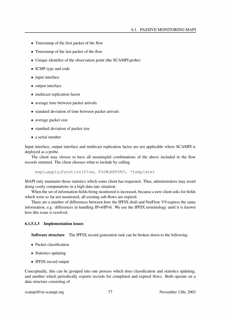
6.1. PASSIVE MONITORING MAPI
• Timestamp of the first packet of the flow
• Timestamp of the last packet of the flow
• Unique identifier of the observation point (the SCAMPI probe)
• ICMP type and code
• input interface
• output interface
• multicast replication factor
• average time between packet arrivals
• standard deviation of time between packet arrivals
• average packet size
• standard deviation of packet size
• a serial number
Input interface, output interface and multicast replication factor are not applicable where SCAMPI isdeployed as a probe.
The client may choose to have all meaningful combinations of the above included in the flowrecords returned. The client chooses what to include by calling
mapi apply function(flow, FLOW REPORT, *template)
MAPI only maintains those statistics which some client has requested. Thus, administrators may avoiddoing costly computations in a high data rate situation.
When the set of information fields being monitored is increased, because a new client asks for fieldswhich were so far not monitored, all existing sub-flows are expired.
There are a number of differences between how the IPFIX draft and NetFlow V9 express the sameinformation, e.g. differences in handling IPv4/IPv6. We use the IPFIX terminology until it is knownhow this issue is resolved.
6.1.5.1.3 Implementation issues
Software structure The IPFIX record generation task can be broken down to the following:
• Packet classification
• Statistics updating
• IPFIX record output
Conceptually, this can be grouped into one process which does classification and statistics updating,and another which periodically exports records for completed and expired flows. Both operate on adata structure consisting of
[email protected] 77 November 13th, 2003

CHAPTER 6. MAPI DEFINITION
• IpfixFlowTable - a table of IpfixFlowRecords, hashed by IpfixFlowKey
• CreatedTimeList - a list of pointers to IpfixFlowRecords, ordered by time the flow record wascreated
• ActiveTimeList - a list of pointers to IpfixFlowRecords, ordered by time the flow record was lastactive
Synchronization Implementing these two conceptual processes as separate operating system pro-cesses or threads is likely to degrade performance. This is because access to the shared data structureshas to be protected by a mutual exclusion mechanism, and acquring the lock will normally be a moreexpensive operation than actually classifying a packet and updating a record. Classification/updatingand record output should therefore be done in the same thread.
Classification Packet classification is done with a hash function. The function has to be cheap tocompute and distribute flows well over the hash buckets. We propose the following fucntion to computea 32 bit hash:
for each possible key field:
if field is a key field for the current scampi flow
xor field value with hash
left shift hash value 8 bits
IPv6 addresses are treated as 4 32 bit fields.The number of hash buckets needs to be high enough to avoid many different IPFIX flows hashing
to the same bucket.
Expiry sub-flows expire and become ready for output when any of the following happens:
• a TCP session is closed.
• it has been inactive for subflow timeout seconds.
• it has existed for max subflow duration seconds.
• When a new client asks for fields which were so far not monitored, all existing sub-flows areexpired.
• Finally, each hierarchical flow has a predefined maximum number for sub-flows: max number of subflows.When a new sub-flow is created but there are already max number of subflows active sub-flows,the one which has been inactive for the longest time is selected and considered expired.
[email protected] 78 November 13th, 2003

6.1. PASSIVE MONITORING MAPI
6.1.5.2 Reading Dynamically Generated Flows
Once a hierarchical flow is created, the user is able to read the expired sub-flows using thefollowing calls:
sub_flow *p = mapi_get_next_subflow(flow_descriptor fd)
If the user does not want to read one expired flow at a time and possibly block, (s)he may reg-ister a callback function that will be called when a sub-flow expires. The following call invokes thecallback handler for each packet that arrives in the network flow fd, and for the next cnt packets.
mapi_subflow_loop(flow_descriptor fd, int cnt,subflow_mapi_handler callback)
callback(flow_descriptor fd, sub_flow * p)
6.1.6 Loadable Functions
MAPI supports dynamic loadable functions, or more generally, libraries of functions, in the followingway: MAPI applications will inform the MAPI daemon mapid for a new library with a new function:
mapi_load_library("newlib.so")\begin{verbatim}
{\tt newlib.so} can be searched out in the same directory,or in a default pathdenoted by MAPI variable {\tt MAPI\_DLIB\_PATH}.The daemon {\tt mapid} will then {\tt dlopen()} this library.Users can from now and on apply functions from the new library as they dofor predefined functions.%, while a slight change is necessary in%mapi_apply_function():%% mapi_apply_function(fd, "newlib_funct1", args...)%% The second argument must be changed to a string, because mapid should know% the names of the functions included in the library to be able to call% them. Another workaround could be to have only one function per file, and% a function like%% funct_id = mapi_load_funct("funct.so", "functname")%% which returns an integer identifying this function. funct_id will then be% passed as the second argument of create_flow(), preserving its current% definition.
\subsection{Some Simple Examples}
[email protected] 79 November 13th, 2003

CHAPTER 6. MAPI DEFINITION
Once we have defined the functionality of the MAPI,lets see how we could use it to implement some simplemonitoring examples.˜\footnote{We should stress that ourexamples are being used for illustration purposes only.Our goal is to demonstrate the expressive power andsimplicity of the MAPI, and not to proposeoptimal solutions. For the same reason, in the exampleswe have chosen to ignore possible errors and exceptions.}
In our first example we are interested in printing the headers of allpackets that are destined to port 80(usually the port used for web servers):\begin{verbatim}#include "mapi.h"char * dev = "/dev/scampi"packet * p ;flow_descriptor fd ;
// create a flow that consists of all packets// destined to port 80fd = mapi_create_flow(dev) ;mapi_set_option(fd, mapi_filter, "dst port 80") ;mapi_connect(fd) ;for (; ;) {
p = mapi_get_next_packet(fd) ;print_header(p);
}
In the following example we count the number of packets (destined to port 80) that have been seenby the system over a period of 10 seconds:
#include "mapi.h"char * dev = "/dev/scampi"flow_descriptor fd ;packet_count_results * r ;int fid ;
fd = mapi_create_flow(dev) ;mapi_set_option(fd, mapi_filter, "dst port 80") ;fid = mapi_apply_function(fd, PACKET_COUNT) ;mapi_connect(fd) ;sleep(10) ; // sleep for 10 secondsr = mapi_read_results(fd, fid, FALSE) ;printf("Read %d packets\n", r.packets) ;
In the following example we print the bandwidth usage per second for our web server (whose IPaddress is 139.91.191.150):
[email protected] 80 November 13th, 2003
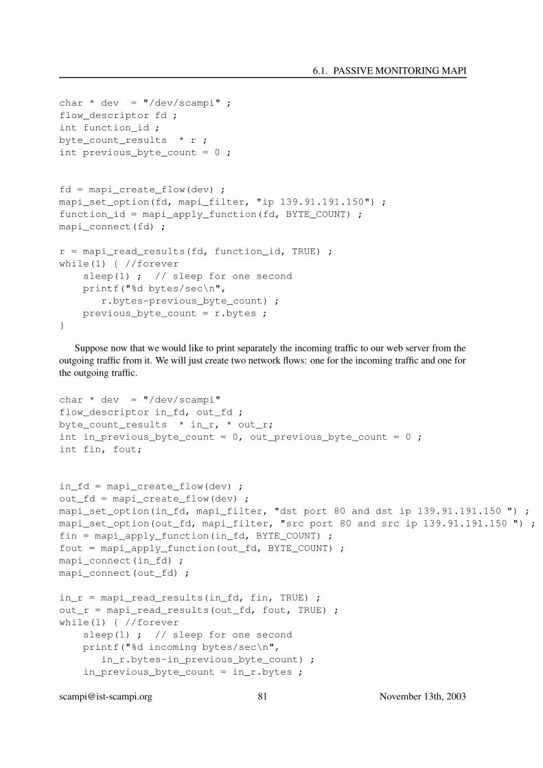
6.1. PASSIVE MONITORING MAPI
char * dev = "/dev/scampi" ;flow_descriptor fd ;int function_id ;byte_count_results * r ;int previous_byte_count = 0 ;
fd = mapi_create_flow(dev) ;mapi_set_option(fd, mapi_filter, "ip 139.91.191.150") ;function_id = mapi_apply_function(fd, BYTE_COUNT) ;mapi_connect(fd) ;
r = mapi_read_results(fd, function_id, TRUE) ;while(1) { //forever
sleep(1) ; // sleep for one secondprintf("%d bytes/sec\n",
r.bytes-previous_byte_count) ;previous_byte_count = r.bytes ;
}
Suppose now that we would like to print separately the incoming traffic to our web server from theoutgoing traffic from it. We will just create two network flows: one for the incoming traffic and one forthe outgoing traffic.
char * dev = "/dev/scampi"flow_descriptor in_fd, out_fd ;byte_count_results * in_r, * out_r;int in_previous_byte_count = 0, out_previous_byte_count = 0 ;int fin, fout;
in_fd = mapi_create_flow(dev) ;out_fd = mapi_create_flow(dev) ;mapi_set_option(in_fd, mapi_filter, "dst port 80 and dst ip 139.91.191.150 ") ;mapi_set_option(out_fd, mapi_filter, "src port 80 and src ip 139.91.191.150 ") ;fin = mapi_apply_function(in_fd, BYTE_COUNT) ;fout = mapi_apply_function(out_fd, BYTE_COUNT) ;mapi_connect(in_fd) ;mapi_connect(out_fd) ;
in_r = mapi_read_results(in_fd, fin, TRUE) ;out_r = mapi_read_results(out_fd, fout, TRUE) ;while(1) { //forever
sleep(1) ; // sleep for one secondprintf("%d incoming bytes/sec\n",
in_r.bytes-in_previous_byte_count) ;in_previous_byte_count = in_r.bytes ;
[email protected] 81 November 13th, 2003

CHAPTER 6. MAPI DEFINITION
printf("%d outgoing bytes/sec\n",out_r.bytes-out_previous_byte_count) ;
out_previous_byte_count = out_r.bytes ;}
The reader will notice that the user application just tells the MAPI what is interested in measuring,and after that it sleeps most of the time. It just wakes up every second to read and print the number ofbytes that have been observed.
In the next example we write the code for trajectory sampling [8]. Trajectory sampling, is applied toall packets in a set of routers in order to determine the trajectories that the packets follow through thoserouters. To do so, first the packets are deterministically sampled by applying a given hash function toall of them and choosing those packets in which the result of the hash function is a given value. Theseselected packets are then sent to a central point which determines the route of the packets through therouters. To reduce the information sent to this central point, a second hash function is applied to thesampled packets, and the result of this second hash function is sent to the central point. The purpose ofthis second hash function is to create a signature that (almost) uniquely identifies each packet.
#include "mapi.h"char * dev = "/dev/scampi"flow_descriptor fd ;
fd = mapi_create_flow(dev) ;//100 and 2 are arguments to the TRAJECTORY_SAMPLING_H functionmapi_apply_function(fd, TRAJECTORY_SAMPLING_H, 100, 2) ;mapi_connect(fd) ;while(1) {
// returns only sampled packetspacket = mapi_get_next_packet(fd) ;signature = hash(packet);sent_to_central_node(signature) ;
}
As we wan see, the application defines a flow consisting of all packets. Then, it tells the system toapply a hash function to those packets and to discard all packets that do not match the value. Thenthe application just reads the (non-discarded) packets of the flow, computes a second hash function onthem, and sends the resulting signature to a central node for processing.
6.1.7 Some More Complex Monitoring Examples
6.1.7.1 Monitoring FTP traffic
In this Section we present an example of using MAPI to monitor all FTP traffic in a system. The maindifficulty with monitoring FTP traffic, as compared to applications like email or web traffic, is thatFTP transfers may be performed over dynamically allocated ports, which are not known in advance.FTP uses a well-known port (i.e. 21) only as a control channel. When a file transfer is initiated, theFTP server informs the client about the dynamic port number to be used for the transfer. Therefore,in order to accurately account for all FTP traffic, a monitoring application needs to monitor port 21
[email protected] 82 November 13th, 2003

6.1. PASSIVE MONITORING MAPI
to find new clients as well as the dynamic ports these new clients will use in order to transfer theirdata. Traditional monitoring systems, such as NetFlow, find it difficult to monitor traffic of applicationsthat use dynamically generated ports. For example, although NetFlow and similar approaches, canreport the amount of observed traffic per port, they do not know which applications these (dynamicallygenerated) ports correspond to, and thus it is difficult to attribute network traffic to specific applications.On the contrary, MAPI is able to analyze packet payloads to find the dynamically generated ports andto associate those ports with the application that generated them.
The following code can ne used to monitor all FTP traffic using MAPI:
packet *p;flow_descriptor fd, xfers[1024];int fid, fid_xfers[1024];struct byte_count_results br;int ports[2], count;unsigned long total_ftp_traffic=0;char new_flow[64];
/* Create a flow to monitor the control port of FTP: port 21 */1a:fd = mapi_create_flow("/dev/scampi);1b:mapi_set_option(fd, mapi_filter, "tcp port 21") ;
/* Find packets that indicate the beginning of a new transfer *//* such packets contain the string "227 Entering Passive Mode" */
2: fid = map_apply_function(fd, SUBSTRING_SEARCH, "227 Entering Passive Mode");
/* Track the next 100 transfers */3: for(count=0; count<100; count++){4: p = mapi_get_next_packet(fd);
/* extract_ports is a function that gets a packet which indicates *//* the beginning of a new transfer and extracts the dynamic data port */
5: extract_ports(p, ports);/* Create a flow to track the forthcoming transfer according *//* to the information contained in the control packet */
6: sprintf(new_flow, "tcp src port %d and dest port %d", port[0], port[1]);/* Create a new flow for this data transfer */
7a: xfers[count] = mapi_create_flow("/dev/scampi", new_flow);7b: mapi_set_option(xfers[count], mapi_filter, new_flow) ;
/* Count the bytes transfered in this flow */8: fid_xfers[count] = mapi_apply_function(xfers[count], BYTE_COUNT);9: print_ftp_traffic() ;
}
print_ftp_traffic() {/* summary */
10: for(count=0; count<100; count++){11: br = mapi_read_results(xfers[count],fid_xfers[count],FALSE);12: total_ftp_traffic += br.bytes;
}print("FTP traffic = %d\n", total_ftp_traffic) ;
}
In order to monitor all FTP traffic, we initially define a network flow for capturing all FTP controlpackets that go through port 21 (line 1:). We are interested only for packets indicating a file transferinitiation, thus substring search is applied to distinguish them among the rest (line 2:). An examplepayload of such packet is the following:
227 Entering Passive Mode (147,52,17,51,146,226)
[email protected] 83 November 13th, 2003

CHAPTER 6. MAPI DEFINITION
This packet is sent by the server and contains the IP address (147.52.17.51) and the port number(37602) of the forthcoming transfer. Therefore, all necessary information for the transfer session isknown so a new flow can be defined for its accounting.
Peer-to-peer, multimedia conferencing and messaging applications usually operate in the samefashion, negotiating transfer ports through a control channel. It is straightforward to adapt the abovecode to monitor the traffic of any of these applications.
Although the above example demonstrates that MAPI can provide traffic information that tradi-tional flow-level traffic summaries, such as Netflow, cannot provide, one could have used a packetdumping facility, such as tcpdump or other libpcap-based tools, in order to find similar informa-tion. However, implementing the above application using libpcap would have resulted in longercode and higher overheads. For example, libpcap does not provide any string searching facility,and thus the programmer would have to provide a significant chunk of code to substitute line 2:above. In addition, libpcap does not provide any facility to apply functions to packets, and thusthe programmer would have to provide a the code to read packets and count their bytes. Instead offorcing the programmer to provide all this mundane code, MAPI already provides this frequently usedfunctionality.
6.1.7.2 Find the average duration of a UDP session
Suppose that we are interested in finding the average duration of a UDP session. Contrary to a TCPsession, a UDP “session” does not have a clearly labeled start and end packet. Thus, a network flowis usually defined as a train of packets that arrive within a short time interval of each other [7]. Inthis case, we can define a hierarchical flow composed of all UDP packets. Each UDP session isnothing more than a sub-flow. The monitoring application will enter a loop receiving one expired flowafter the other. For each flow it will find the duration of the flow (i.e. duration of the UDP session)by subtracting subflow start time from the subflow end time. Calculating the average ofsuch durations is then straightforward.
6.1.7.3 Find the average duration of a TCP session
Suppose that the user would like to find the average duration of a TCP connection. As a first cut, thiscan be done in the same way as described previously in the UDP sessions. However, in this paragraphwe will describe another way of doing it. The user may create one flow with the starting packets of aconnection (i.e. those that have the SYN flag set), and one flow with the closing packets (i.e. those thathave the SYN/FIN flag set). The user application in turn will correlate packets from these two flows inorder to find the TCP sessions and their duration.
6.1.8 Implementation issues for MAPI
The described MAPI can be easily implemented on top of today’s systems at various levels. It can beimplemented in user-space (on top of libpcap), in kernel-space (in cooperation with BPF or LSF), or(some subsystems of MAPI) at specialized hardware.
For example, MAPI can be implemented on top of libpcap as follows: libpcap will provide allpackets, which will be later categorized (by the MAPI implementation) into network flows.
MAPI can also be implemented inside the operating system kernel as a add-on to the BerkeleyPacket Filters [17] or Linux Socket Filters [11]. In this case, the operating system will be able to doa significant amount of packet processing in kernel space without ever delivering the packets in user
[email protected] 84 November 13th, 2003

6.1. PASSIVE MONITORING MAPI
level. The MAPI can be also implemented in a system with special-purpose hardware, like a special-purpose network interface. The special-purpose network interface will implement some of the MAPI’sfunctionality, probably the filtering and the categorization of packets into flows. Finally, the MAPIcan also be (partially) implemented on top of traditional systems that can communicate with intelligentrouters that keep statistics about the incoming traffic. In this case, the MAPI will provide only thefunctions already implemented by the router. It will simply not provide the rest of the functions.
6.1.8.1 MAPI for High-Speed Monitoring
The MAPI described has been especially designed for easy, and high-speed network monitoring. Forexample, user applications are allowed to define network flows which clearly separate the varioussources of traffic. Thus, the user will be able to treat each flow of traffic differently, and focus ofdifferent flows at different times. In addition, users are able to define functions to be executed oneach packet. Thus, the system may choose to execute these functions in the best possible place: theuser-space, the kernel-space, a co-processor, or some special-purpose hardware.
6.1.8.2 MAPI for clock control
MAPI has to deal with clock for timestamp generation, whether the clock is implemented in software(kernel) or in hardware (on the adapter). A hardware clock on the adapter can be accessed via amapi ioctl call.
Timestamps are represented by the timespec structure adopted from nanokernel implementation:
struct timespec {long tv_sec; /* # of UTC seconds since 0:0:00, 1970, January 1 */long tv_nsec; /* nanoseconds since beginning of current second */
}
6.1.8.2.1 Functions
mapi_gettime (struct timespec *ts)
Function returns current time of the clock. Function is not used for timestamp generation, as it isdone earlier and automatically in adapter or by driver.
mapi_settime (struct timespec *ts)
Function sets the adapter clock to the given value.
mapi_adjtime (long offset, long skew)
Function adjusts clock rate and offset in case clock is not disciplined by NTP process or externaltime source.
mapi_discipline (int par)
Function start and stops disciplining of the adapter clock by external signal (for instance PPS -PulsePer Second- signal from GPS receiver)
[email protected] 85 November 13th, 2003

CHAPTER 6. MAPI DEFINITION
6.1.8.3 Management
For management purposes MAPI will provide information about the status of the monitoring hardwarethat is used and basic usage statistics. All management information will be available through a singlecall:
management_info *result = get_management_info(int info_type)
where info type specifies the type of management information that should be returned.
6.1.9 Options for MAPI Interfaces
A SCAMPI application can be implemented as an SNMP client, which contacts a SCAMPI SNMPagent. This SNMP agent offers exactly the same functionality as the MAPI (configuration of the clickbuilding blocks to receive the desired outputs). Results can be sent to the SNMP client by either SNMPtraps (asynchronous) of as a response to an SNMP GET REQUEST. However, SNMP has a few draw-backs in this context: (i) since SNMP communication makes implicit use of the UDP protocol, com-munication is not reliable, (ii) SNMP does not provide any support for transactional operations, (iii)a lot of implementations which suffer from buffer overflow have been reported, (iv) the SNMP agentscan only contact the clients by means of traps, and (v) SNMP only provides very limited support forauthentication. Authentication is available in SNMPv3. However, very few implementations of SN-MPv3 exist. A SCAMPI application can also be implemented as a PDP (Policy Decision Point), whichcontacts the SCAMPI PEP (Policy Enforcement Point) via COPS (Common Open Policy Service).However, the deployment of a COPS interface to the MAPI poses a few problems: (i) there is currentlyno support in e.g. HPOpenview for managing COPS PEPs., (ii) there is only a small COPS codebasein the Internet community and (iii) COPS implementations are rather complex.
6.2 MAPI vs. Other Approaches
Current network monitoring tools use a wide variety of languages and environments, including libpcap[16], Berkeley Packet Filters [17], CoralReef [14], Linux Socket Filters [11], IPFIX [23], and NET-FLOW [28]. The notion of network flow, has been introduced in monitoring systems several years ago.For example, a flow has been defined as a “sequence of related packets sent from a source to a unicast,anycast, or multicast destination(s)” [24]. The notion of a flow has also been widely used by CISCO inits various network monitoring products including NetFlow [28]. A similar notion of a flow is currentlybeing standardized in IPFIX. However, contrary to other definitions, MAPI gave the “network flow” afirst-class status. For the first time and contrary to previous proposals and implementations, flows inMAPI have a name, they have an identification. Users can access their flows by their id. Users cancreate flows, they can destroy (close) flows, they can read packets from a flow. Users can also applyfunctions to flows; they can sample packets from flows; they can count packets, bytes and various trafficstatistics in a flow; in short they can operate on flows, much like they can operate in other programmingabstractions like sockets, pipes, files, etc. Using these first-class flows users are able perform a widevariety of new monitoring operations. For example, MAPI network flows enables users to developintrusion detection systems that are based on full packet payload inspection. On the contrary, NetFlow,IPFIX, and related systems and proposals (to the best of our understanding) do not provide full contentinspection, and thus they cannot be used to implement signature-based intrusion detection.
Besides the notion of the flow, MAPI shares functionality with previously defined network mon-itoring systems. For example, Berkeley Packet Filters [17] can filter monitored traffic much like the
[email protected] 86 November 13th, 2003

6.3. APPLICATIONS THAT USE MULTIPLE OBSERVATION POINTS
conditions of the network flows do. As another example, Linux Socket Filters [11] associate a socketwith each filter, much like MAPI associates a network flow with one condition. However, no pre-vious such filtering environment allowed users to fully express their real monitoring needs. Userswith somewhat complex monitoring requirements usually completely bypassed the underlying filteringmechanism and re-implemented their filtering inside their applications much like the snort intrusiondetection system does [26]. MAPI is the first network monitoring abstraction that uses a language richenough to allow users express complex monitoring needs and enables the system to implement them asefficiently as possible. For the first time, users are able to tell the monitoring system that they want onlythose packets that match a virus signature; or that they just want a head count of the packets to theirweb server, achieving both expressive power, and increased efficiency. This expressiveness enablesMAPI-based applications to efficiently perform a wide variety of applications that is not possible withsystems such as pcap and LSF. For example, lets assume that we have an intelligent network adapterequipped with a programmable processor. Assume also that the monitoring application would like tosample the packets and receive one out of every 100 packets of the entire network traffic. User appli-cations on top of MAPI have the ability to express this sampling requirement, which, in turn, MAPImay implement it in the programmable processor on the network adapter. Thus, only one percent of thenetwork traffic will be transfered from the adapter to the host processor. On the contrary, applicationsrunning on top of pcap or LSF have no way of stating this sampling requirement. As a result, theywill be forced to receive the entire 100% of the traffic, only to throw away 99% of it. Summarizing,by letting users express their needs, and by giving network flows a first-class status, MAPI enablesthe efficient implementation of monitoring applications on top of a wide variety of platforms. networkflows a first-class status, MAPI enables the efficient implementation of monitoring applications on topof a wide variety of platforms.
6.3 Applications that use multiple observation points
So far, we only addressed applications that require monitoring information from a single observationpoint. In these cases the applications run locally on the observation point. The observation point bothgathers the required information and does the processing of the captured data.
Advanced applications require not only information from a single observation point, they needmonitoring data from the entire network. Therefore, the application needs to obtain information frommultiple distributed points in the network. Consider a Quality of Service (QoS) application. Thisapplication needs to determine network characteristics such as throughput, loss, jitter, goodput, delay,...These characteristics can only be computed if we have information from at least both the ingress andegress nodes in the network.
The current MAPI supports these kinds of applications. To do so, a distributed application needs tocreate multiple network flows, at least one for each observation point, by using the “remote” MAPI8.
6.3.1 The Remote MAPI
The interfaces of the “remote” MAPI and the “local” MAPI are very similar, if not the same. Based onthe use of the interface, the SCAMPI platform will internally behave different. The only remarkabledifference is the location of the invocation of certain function-calls. In the case of the “local” MAPI,every function is executed on the local monitoring agent. There is no need to specify the locationof the observation point. When the MAPI is used to initiate a monitoring job remotely, the location
8From a programmer’s point-of-view, the remote MAPI and the local MAPI are functionally the same.
[email protected] 87 November 13th, 2003

CHAPTER 6. MAPI DEFINITION
and identification of the monitoring agent needs to be specified. The application has to specify whichobservation point should run the monitoring job. Obviously, each participating observation point hasto run the MAPI daemon.
An application that needs to monitor a remote observation point, needs to use a MAPI with re-mote functionality. Therefore we extended the MAPI library to allow remote executions. In this case,the mapi create flow function has to be extended with a location/identity parameter to locate oridentify the observation point. ¿From an implementation point-of-view, instead of inter-process com-munication (IPC) to communicate with the MAPI daemon, the remote MAPI uses remote procedurecalls (RPC).
When the observation point is located on a different machine than the client application, the appli-cation can specify the location in the mapi create flow function call:
mapi_create_flow(device);
In the case of a remote MAPI, the device will specify both the interface the flow should be capturedfrom, and the IP address of the host the observation point is running on. The format of “device” is:
Device = ‘‘Interface@IPaddress’’ e.g. ‘‘[email protected]’’
When no IP address is specified, i.e. device = “interface”, the MAPI assumes the observationpoint is running on the local host, i.e. we use the local MAPI. When on the other hand interface =“DEFAULT”, the application captures the flow from its default interface (in case the observation pointhas for example only one interface).
6.3.2 Creating multiple network flows
A second step in writing a distributed monitoring application is to open multiple network flows, at leastone on each observation point. After retrieving monitoring results from these flows, the application canprocess and correlate them. The processing and correlation of the data obtained from the distributedsites is the responsibility of the applications. The MAPI only offers the programmer the opportunity toeasily obtain distributed data.
The following example illustrates a basic application that requires 2 observation points.
int fd1, fd2;int counter1, counter2;unsigned long long result1, result2;
fd1 = mapi_create_flow("[email protected]");mapi_apply_function(fd1, BPF_FILTER, "SRC 10.0.0.1 and DST 10.0.0.2");counter1 = mapi_apply_function(fd1, PKT_COUNTER);
fd2 = mapi_create_flow("/dev/[email protected]");mapi_apply_function(fd2, BPF_FILTER, "SRC 10.0.0.1 and DST 10.0.0.2");counter2 = mapi_apply_function(fd2, PKT_COUNTER);
mapi_connect(fd1);mapi_connect(fd2);
sleep(60);result1 = mapi_read_results(fd1, counter1,FALSE);result2 = mapi_read_results(fd2, counter2,FALSE);
printf(.There were %lld packets dropped\n., counter1 . counter2);
mapi_close_flow(fd1);mapi_close_flow(fd2);
[email protected] 88 November 13th, 2003

6.3. APPLICATIONS THAT USE MULTIPLE OBSERVATION POINTS
In this application 2 flows are configured, one on the observation point with IP address 10.0.0.1(the ingress) and one on the observation point with IP address 10.0.0.2 (the egress). Both the Flowscount all the packets with source address the first observation point and destinations address the secondobservation point. After one minute, the application prints the number of dropped packets sent fromobservation point 1 to 2. This very basic example illustrates how an application can use both the remoteMAPI and the creation of multiple flows in order to monitor distributes sites. After the configurationof both flows, the application only needs to correlate and process the retrieved data.
[email protected] 89 November 13th, 2003


Chapter 7
Summary
This document presented a detailed description of the SCAMPI architecture - both software and hard-ware. We believe that we have introduced a novel architecture that can be efficiently implemented inhigh-speed networks. Capitalizing on powerful abstractions, such as the first-class network flows, andon expressive ability, such as that provided by function application to flows, the SCAMPI architectureis in a unique position to provide a solution for high-speed network monitoring.
The impact of SCAMPI on efficiency and ease of programming is expected to increase as net-works get faster, monitoring applications become more complex, and hardware-supported monitoringbecomes more prevalent. We expect that SCAMPI will provide an effective platform which enablesapplications to express their needs and allows the underlying monitoring system to optimize the imple-mentation in the best possible way.
91


Appendix A
Language for Network Flow Conditions
When a new flow is created, a condition is given among the arguments needed to create theflow. The condition is nothing more than a filter that enables users to express to the systemthe subset of traffic they are interested in monitoring. In this way, (i) the users receive onlythe information they need, and (ii) the system is able to reduce the amount of traffic sentin user-space and thus to improve its performance. The language that users use to expresstheir conditions should be powerful enough to express most frequently occurring condi-tions, and at the same time it should be simple enough so as to be efficiently implemented.At the same time, it should be extensible so that users will be able to express requirementsthat we do not currently know.
Within SCAMPI we have chosen to use a dual approach to expressing the above condi-tions:
• We will use a known and frequently used language to express such filters, and
• We will enable users to further restrict the packets they are interested in observingthrough the application of functions to network flows.
Thus, the language that we will use to express conditions will be the one used by BerkeleyPacket Filters [17]. It is interesting to note that the same language is being used in tcpdump[30], in Linux Socket Filters [11], and in libpcap [16].
The language allows users to test for equality, inequality, and range conditions for allknown IP header fields. For example
host calliope.ics.forth.gr
returns all network packets sent to/from calliope.ics.forth.gr. Or,
dst port 80
returns all packets whose destination port is 80 (which usually corresponds to web traffic).If a user would like to trace all packets between local hosts and the hosts at the Universityof California at Berkeley the following command returns just them:
net 128.32
93

APPENDIX A. LANGUAGE FOR NETWORK FLOW CONDITIONS
Actually, the user is also able to access bytes within packets using a array-like notation.For example,
ip[2:2] > 100
returns all IP packets whole length is greater than 100. The ip[2:2] returns the 2 bytesstarting at the third byte of the IP header (i.e. the ip[2]). These two bytes represent thelength of the IP packet.
Note that although the above language can test for quality of inequality all fields of an IPpacket, it may still not be enough for very sophisticated users that would like to performmore complicated conditions. For example, some users may also want to test whetherpackets contain specific substrings (like in intrusion detection systems [26]), or they maywant to perform sophisticated sampling, like in trajectory sampling [8]. We believe thatthis functionality can be implemented in SCAMPI on top of the above condition languageby defining appropriate functions and by applying the functions to the packets of the net-work flow.
[email protected] 94 November 13th, 2003

Appendix B
Predefined Functions for Network Flows
The MAPI implementation will provide a large set of predefined functions that will be applied tonetwork packets. Such functions include:
PKT_COUNTER
structure of results:struct packet_count_results {uint64_t packets ;} ;
It keeps the number of packets seen by the flow so far.
STR_SEARCH(unsigned char *s, int len, int offset, int depth)
structure of results: none
It searches the body of the network packet to see if it contains string s of length len 1. Thesearch starts from byte offset and lasts for depth bytes. If substring s is not found,the packet is discarded.
BYTES_IN_INTERVAL(unsigned long us)
structure of results:struct packets_in_interval_count_results {struct timeval start ;uint64_t packets ;} ;
It keeps the number of octets observed in a time interval. The length of the interval inmicroseconds is the input parameter us. The start of the interval is return in the resultsstructure, along with the number of the packets observed.
1Note that the string s may contain the character ’0’ as one of its characters.
95

APPENDIX B. PREDEFINED FUNCTIONS FOR NETWORK FLOWS
DISCARD
structure of results:struct discard_results {uint64_t discared_packets ;} ;
It discards the current packet. It is being used when users are not really interested inreceiving packets, but are only interested in calculating statistics in network flows.
SAMPLE_PACKETS(int sample_period, int mode)
structure of results: none
It samples packets from the network flow. All but one out of every sample periodpackets are discarded and never sent to the monitoring application. If the mode is DETERMINISTIC,the sampling is deterministic. If mode is PROBABILISTIC, the sampling is probabilisticwith samples taken from a uniform distribution. Sampling functions represent the mostfundamental functionality of several monitoring environments, including sflow [22].
ADDITIVE_HASH (char *packet, int offset, int len, int prime, int low, int high){int hash, i;for (hash=len, i=offset; i<len; ++i)
hash = hash+packet[i];return (hash % prime);
}
structure of results: none
It computes the additive hash function. It keeps the packet if the resulting value is betweenlow and high. Otherwise, it discards the packet.
TRAJECTORY_SAMPLING_H(char *packet, int len, int A, int r )
structure of results: none
It computes the h(φ(x)) function as described in [8], and then takes the h(φ(x)) mod A. Ifthe result is larger than or equal to r the packet is discarded.
TRAJECTORY_SAMPLING_G(char *packet, int len ,int B)
It computes the g(φ(x)) function as described in [8].
PACKET_SAVE(int startbyte, int endbyte)
structure of results: none
[email protected] 96 November 13th, 2003

It defines the portion of the packet that is to be reported to the application. It is useful totrace specific portions of the packets (such a s application-level header structures). Thisfunctionality is similar to the tcpdump syntax for specifying bytes ranges to be traced (forexample: tcp[20:10]). The tracing of disjoint portions is not allowed. If endbyte is 0,the function saves up to the end of the packet.
[email protected] 97 November 13th, 2003

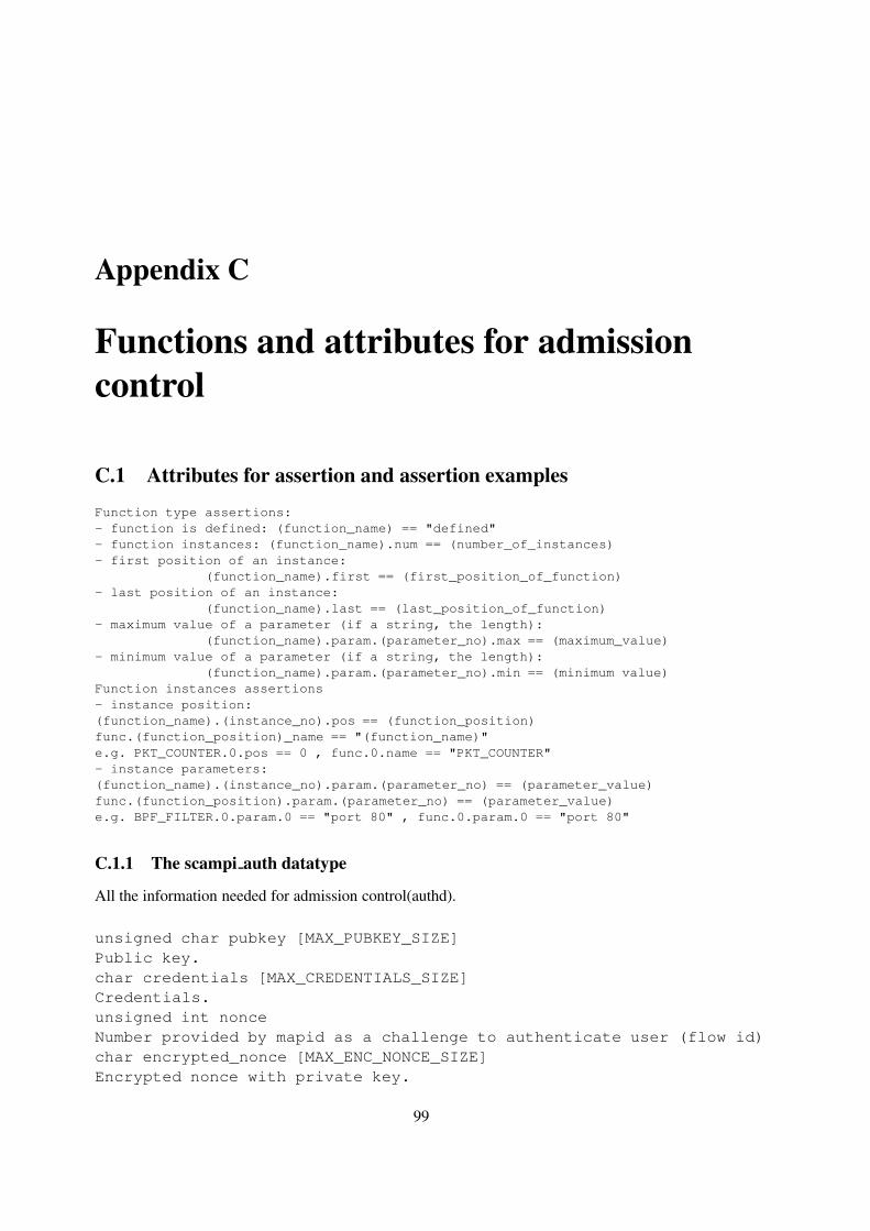
Appendix C
Functions and attributes for admissioncontrol
C.1 Attributes for assertion and assertion examples
Function type assertions:- function is defined: (function_name) == "defined"- function instances: (function_name).num == (number_of_instances)- first position of an instance:
(function_name).first == (first_position_of_function)- last position of an instance:
(function_name).last == (last_position_of_function)- maximum value of a parameter (if a string, the length):
(function_name).param.(parameter_no).max == (maximum_value)- minimum value of a parameter (if a string, the length):
(function_name).param.(parameter_no).min == (minimum value)Function instances assertions- instance position:(function_name).(instance_no).pos == (function_position)func.(function_position)_name == "(function_name)"e.g. PKT_COUNTER.0.pos == 0 , func.0.name == "PKT_COUNTER"- instance parameters:(function_name).(instance_no).param.(parameter_no) == (parameter_value)func.(function_position).param.(parameter_no) == (parameter_value)e.g. BPF_FILTER.0.param.0 == "port 80" , func.0.param.0 == "port 80"
C.1.1 The scampi auth datatype
All the information needed for admission control(authd).
unsigned char pubkey [MAX_PUBKEY_SIZE]Public key.char credentials [MAX_CREDENTIALS_SIZE]Credentials.unsigned int nonceNumber provided by mapid as a challenge to authenticate user (flow id)char encrypted_nonce [MAX_ENC_NONCE_SIZE]Encrypted nonce with private key.
99

APPENDIX C. FUNCTIONS AND ATTRIBUTES FOR ADMISSION CONTROL
unsigned int encrypted_nonce_lenThe length of the encrypted nonce.char device_name [MAX_DEVICE_NAME_SIZE]The name of the device associated with this flow.char app_domain [MAX_APP_DOMAIN_SIZE]The application domain of this request. Should be "MAPI".unsigned int functions_numThe number of the serialized functions in the buffer.unsigned char function_list [MAX_FUNCTION_LIST_SIZE]The buffer with the serialized function list.
C.1.2 The flow auth datatype
Results returned by admission control(authd).
int PCVAsserted if the flow is authorizedmapi_resources required_resources;Amount of required resources.
C.1.3 The scampi resources datatype
Resources can be of various types. Currently the following two are defined
unsigned int processing;Processing time.unsigned int memory;Memory consumption.
C.1.4 mapid writing and reading the shared memory
int mapid_shm_store(void *seg,int flow_id)Parameters:seg the shared memory segmentflow_id the flow id to get data fromReturns: 0 on success, or -1 on failure
int mapid_shm_retrieve(void *seg,flow_auth *f)Parameters:seg the shared memory segmentf pointer to variable to copy data intoReturns: 0 on success, or -1 on failure
[email protected] 100 November 13th, 2003

Appendix D
Man pages for MAPI functions
D.1 MAPI functions
flow_descriptor fd =mapi_create_flow(char *device_d)
create flow is used for creating a new network flow of packets. The flow of packetswill be read from device device d. If unsuccessful, it returns a negative number.
int mapi_close_flow(flow_descriptor fd)
mapi close flow is used to close the flow defined by descriptor fd and deallocateresources. If successful it returns a non-negative integer. Otherwise, it returns a negativeone.
int mapi_connect(flow_descriptor fd)
mapi connect is used to connect to the flow fd and start receiving information. Thecall may fail depending on the requestor’s privileges and requirements. If successful itreturns a non-negative integer. Otherwise, it returns a negative one.
mapi_set_flow_option(flow_descriptor fd, int option, void * value)
set flow option is used to configure flowfd, by assigning option value to option.
void * mapi_get_flow_option(flow_descriptor fd, int option)
get flow option is used to gather information about the configuration of a flow fd,by returning a pointer to the value of option option.
packet *p = mapi_get_next_packet(flow_descriptor fd)
get next packet returns a pointer to the next available packet for flow fd. If no suchpacket exists, the call blocks until such a packet is received. The packet p is a sequenceof bytes. This sequence starts with a header and continues with the network packet itself.The actual format of this sequence can be found later in this appendix when talking aboutthe monitoring record format option.
101

APPENDIX D. MAN PAGES FOR MAPI FUNCTIONS
int mapi_loop(flow_descriptor fd,int cnt, mapi_handler callback)
void callback(flow_descriptor fd, void * packet)
If users do not want to block in the process of receiving network packets from a flow usingthe tt get next packet call, they may invoke the mapi loop call which invokes handlercallback after it has received a packet of flow fd. The handler callback is invokedfor the next cnt packets of flow fd. If cnt is -1, callback is invoked for all futurepackets of flow fd.
int function_id = mapi_apply_function(flow_descriptor fd, char* f,...)
mapi apply function applies function f to all packets of the network flow fd. Thefunction may compute statistics, hash functions, or anything else. If the application issuccessful, it returns a non-negative integer. Otherwise, it returns a negative one.
int mapi_load_library(char * libname)
mapi load library informs MAPI that the user is interested in using functions de-fined in library libname. The library is searched in the current directory as well as inthe path defined in variable MAPI DLIB PATH. If everything is successful, the functionreturns a non-negative integer. Otherwise, it returns a negative one.
int mapi_remove_function(flow_descriptor fd, int function_id,...)
remove function removes function f from being applied to packets of network flowfd. If no such function exists, a negative value is returned.
int mapi_save_to_disk(flow_descriptor fd, int file_descriptor,...)
mapi save to disk saves all packets of network flowfd to the file file descriptor.If the function fails, a negative value is returned.
void * mapi_read_results(flow_descriptor fd, int function_id, int copy)
read results will receive statistics or any kind of results that have been computedby the application of function function id in the packets of flow fd. The resultswill be returned in a structure pointed to by the return value of the function. If copyis FALSE, then the pointer points to a memory region shared between the mapid andthe user application. This region is exactly the place where the MAPI daemon writes theresults of the function. The application may continually access the updated results throughthe pointer to this shared region without re-invoking the mapi read results function.This shared region can also be used to efficiently transfer large amount of results from thedaemon to the application. If copy is TRUE the results are copied in a separate memoryregion that will not be continually updated by the MAPI daemon.
MAPI can collect statistics on a flow using Flow Records. This is achieved with two variables.FLOW RECORD is a logical variable which when set to TRUE enables the c collection of Flow Records.FLOW RECORD TYPE can take values from the set {IPFIX, NETFLOW V5 NETFLOW V9}, select-ing the format of the records that MAPI will maintain.
To read the collected flow records, an application can use the read flow record function:
[email protected] 102 November 13th, 2003

D.1. MAPI FUNCTIONS
void * mapi_read_flow_record(flow_descriptor fd)
read flow record returns a flow record of the flow fd. The type of the record isIPFIX , NETFLOW V5, or NETFLOW V9, depending on the value of FLOW RECORD TYPE.
sub_flow *p = mapi_get_next_subflow(flow_descriptor fd)
get next subflow finds the next expired subflow of the hierarchical flow fd. Thefunction returns a pointer to a structure of type sub flow. This call is blocking.
int mapi_subflow_loop(flow_descriptor fd,int cnt, subflow_mapi_handler callback)
If the users do not want to block while waiting for sub-flows to expire, subflow loopenables them to install a handler callback that will be invoked for the next cnt expiredsubflows. If cnt equals -1, then callback will be invoked for all sub-flows that willexpire in the future.
int mapi_settime (struct timespec *ts)
mapi settime sets the adapter clock to the given value.
int mapi_adjtime(long offset, long skew)
mapi adjtime adjusts clock rate and offset in case clock is not disciplined by NTPprocess or external time source.
int mapi_discipline(int par)
mapi discipline start and stops disciplining of the adapter clock by external signal(for instance PPS -Pulse Per Second- signal from GPS receiver)
int mapi_discipline(int par)
mapi discipline start and stops disciplining of the adapter clock by external signal(for instance PPS -Pulse Per Second- signal from GPS receiver)
management_info *result = get_management_info(int info_type)
get management info will provide information about the status of the monitoringhardware that is used and basic usage statistics.
[email protected] 103 November 13th, 2003

APPENDIX D. MAN PAGES FOR MAPI FUNCTIONS
D.2 MAPI Variables
The options available for network flows are 1:
packet_size
The size of packets in cooked network flows. The default value if 64 Kbytes.
mapi_mode
Mode mode defines the type of the flow: RAW, COOKED, and HIERARCHICAL. If suc-cessful, the function returns a non-negative integer flow descriptor fd. The defaulttype of a newly-created flow is RAW.
(char *) mapi_filter
All packets of the flow that do not match filter filter are discarded. filter is ex-pressed in the language used by tcpdump. For example ‘‘host arion’’ matchesall packets arriving to or departing from host arion. Similarly ‘‘dst port 80’’matches all packets which are destined to port 80.
packet_length
The maximum number of bytes of each packet that the monitoring environment will returnto user applications. It can be adjusted to improve privacy and performance. Its defaultvalue is 64 bytes.
number_of_sub_flows
The number of bytes of sub-flows for each hierarchicalflow. Is default value is 32K.
subflow_timeout
If no packet arrives for a subflow within subflow timeout milliseconds, the flow isconsidered expired. The default value is one second.
max_flow_duration
The maximum duration of a network subflow. When the “life” of the flow exceeds max flow duration(measured in milliseconds), the flow is considered expired. The default value is 15 min-utes.
interface_number
When a device has more than one interfaces, interface number will be used to dis-tinguish among them. Actually, interface number is a bitmask. When its ith bit isset, the flow receives packets from the ith interface. If more than one bits are set, theflow receives packets from all these interfaces. Suppose for example that a DAG card(“/dev/dag”) has two interfaces. Using the following code, all packets from interface num-ber 0 will arrive in flow fd1, and all packets from interface number 1 will arrive in flowfd2:
1Recall that these options may be modified with the set flow option(flow descriptor, fd, intoption, int value) function.
[email protected] 104 November 13th, 2003

D.2. MAPI VARIABLES
int if1 = 1 ; /* 0...0001 */int if2 = 2 ; /* 0...0010 */
packet * p1, p2 ;
fd1 = mapi_create_flow("/dev/dag") ;mapi_set_flow_option(fd1, interface_number, &if1);p1 = mapi_get_next_packet(fd1) ;
fd2 = mapi_create_flow("/dev/dag") ;mapi_set_flow_option(fd2, interface_number, &if2);p2 = mapi_get_next_packet(fd2) ;
no_copy
If no copy is TRUE, the application declares that it does not want to receive any packetsin user space. It created the network flow just to apply functions to its packets and gatherstatistics. Thus, when packets arrive, the MAPI implementation does not keep a copy ofthem around for possible delivery to user applications. The default value is FALSE.
filter
It returns a string containing the filter c that was initially used to create this flow using thecreate flow(device d, c, m) MAPI call.
total_number_of_packets
The total number of packets captured by the flow
total_number_of_octets
The total number of octets captured by the flow
total_number_of_dropped_packets
The total number of dropped packets during the packet capture by the by the flow.
flow_record
If flow record is TRUE, then the system gathers statistics for this network flow.
flow_record_type
The value of flow record type denotes the format in which applications would like toreceive the collected statistics for this network flow. It can get values IPFIX,NETFLOW V5,and NETFLOW V9,
monitoring_record_format
[email protected] 105 November 13th, 2003

APPENDIX D. MAN PAGES FOR MAPI FUNCTIONS
This option defines that format of the packet records that will be returned to applicationsinterested in passive monitoring. The get next packet function returns a pointer tostructure that has some metadata about the packet followed by the IP network packet itself.It can take several values including:
• PLAIN: it returns just a timestamp and the length of the IP packet that immediatelyfollows the structure :
struct plain_data {struct timeval ts ;int16_t ip_packet_len ;
}
Thus, if the user executes the following code:
packet * p = mapi_get_next_packet(fd) ;
then the timestamp is at
((struct plain_data *) p)->ts,
the packet length is at
((struct plain_data *) p)->ip_packet_len},
and the IP packet starts from
p+sizeof(struct plain_data),
We should probably stress that all the above pointer operations do not necessarilyneed to copy data between kernel space and user space. Indeed the can be imple-mented using the mmap system call in a transparent way. For example, the user-levelMAPI library may decide to mmap a portion of memory that will be shared betweenuser space and kernel space. In this way, the SCAMPI monitoring system that willreside in kernel space will write all network packets in this spared space, and the user-level MAPI implementation in response to the get next packet call will returnpointers that reside within this memory mapped range. This memory mapped rangemay be as large as the monitoring library wants, so that wrapping of the pointerswill not turn out to be a significant problem. On the other hand, we must stress thatthis memory mapped region can not be infinitely sized. Thus, if a user applicationcontinues to receive packets the get next packet will eventually need to reusepointer values. This implies that get next packet returns the next packet in aportion of memory that may be overwritten in some (possibly distant) future call ofget next packet. Thus, if users would like to have several outstanding packetsin main memory, they will eventually need to allocate memory for them.
• DAG ERF GLR: this is the generic variable length record of the extensible recordformat supported by the DAG cards. We expect it to be used when the monitoringsystem is implemented on top of DAG cards.
struct dag_record {unsigned long long ts;unsigned char type;flags_t flags;
[email protected] 106 November 13th, 2003

D.2. MAPI VARIABLES
unsigned short rlen;unsigned short lctr;unsigned short wlen;union {pos_rec_t pos;eth_rec_t eth;atm_rec_t atm;} rec;} ;
• ETHERNET HEADER: it returns the packet along with its Ethernet headers and thelength of the IP packet:
struct ethernet_header_data {struct timeval ts ;struct sniff_ethernet sf ;int16_t ip_packet_len ;
}struct sniff_ethernet {
/* Destination host address */u_char ether_dhost[ETHER_ADDR_LEN];/* Source host address */u_char ether_shost[ETHER_ADDR_LEN];u_short ether_type; /* IP? ARP? RARP? etc */
};
FLOW PACKET RECORDS: it returns flow/packet records as described in [10]. A “packet”in this format is actually a sequence if packet records headed by a flow record 2 as describedbelow:
struct flow_record {uint8_t protocol ;uint8_t flags ;uint16_t record_number ;uint64_t timestamp ;uint32_t source_address ;uint32_t destination_address ;uint16_t source_port ;uint16_t destination_port ;uint32_t initial_sequence_number ;uint32_t initial_ack_number ;uint32_t number_of_packet_records_that_follow ;
}
2We should make clear that a flow record as defined in [10] is different from a flow record returned by functionread flow record. The first contains some packet header fields as defined in [10], while the latter contains statistics(like packet count, byte count, etc.) about a flow.
[email protected] 107 November 13th, 2003

APPENDIX D. MAN PAGES FOR MAPI FUNCTIONS
struct packet_record {uint64_t timestamp ;uint16_t total_length ;uint16_t identification ;uint8_t type_of_service ;uint8_t time_to_live ;uint8_t tcp_flags ;uint8_t flags ;uint16_t sequence_number_offset ;uint16_t ack_number_offset ;uint16_t ip_packet_len ;
}
flow_packet_records_length
flow packet records length is used with the FLOW PAKCET RECORDS formatto set the maximum number of bytes that the user is willing to accept in the future invoca-tions of get next packet call. flow packet records length is necessary be-cause in the FLOW PAKCET RECORDS there is no pre-set limit on how much informationthe system in going to return to the user, because the system does not return one networkpacket at-a-time, but a potentially large sequence of them. Thus, the users should tell themonitoring system how much bytes they have allocated, and based on this information thesystem should decide how many packets it should send them.
MAPI_DLIB_PATH
MAPI DLIB PATH contains the path of the directories where libraries of functions can beloaded using the mapi load library call.
D.3 Variables for Hierarchical Flows
For each sub-flow kept within a hierarchical flow, the system keeps the following variables:
subflow_number_of_packets
The number of packets seen in the sub-flow
subflow_number_of_bytes
The number of bytes in the packets of this sub-flow.
subflow_start_time
The timestamp of the first observed packet of the sub-flow.
subflow_end_time
The timestamp of the last observed packet of the sub-flow.
[email protected] 108 November 13th, 2003

D.3. VARIABLES FOR HIERARCHICAL FLOWS
avg_time_between_packet_arrivals
The average time between successive packet arrivals in microseconds.
std_dev_time_between_packet_arrivals
The standard deviation of the time between successive packet arrivals.
avg_packet_size
The average packet size.
std_dev_packet_size
The standard deviation of the packet sizes.
All the above variables are packed in a structure as follows:
struct sub_flow {long subflow_number_of_packets ;long subflow_number_of_bytes ;long subflow_start_time ;long avg_time_between_packet_arrivals ;double std_dev_time_between_packet_arrivals ;int avg_packet_size ;double std_dev_packet_size ;}
[email protected] 109 November 13th, 2003


Appendix E
Header Files
E.1 mapi.h
#ifndef _MAPI_H#define _MAPI_H 1
#include <sys/ipc.h>
#define PAPI 10
#include "mapi_errors.h"
#ifndef TRUE#define TRUE 1#endif
#ifndef FALSE#define FALSE 0#endif
/* NOTE: When more functions are added, also update the array inadm_ctrl/scampi_auth.c with the name of the function */
typedef enum {PKT_COUNTER, /* Count the packet */STR_SEARCH, /* Search the specified string */BPF_FILTER, /* Filter the packet */TO_BUFFER, /* Copies packets to a buffer that can beread by user applications */ETHEREAL, /* ethereal filter, uses the ethereal display filter to filter pkts */TO_TCPDUMP, /* Create tcpdump file format from captured packages */BYTE_COUNTER /* Count the bytes passing through the filter */
} mapiFunction;
typedef unsigned char mapiFunctArg;
/* Replaced by the following enumeration* Also used by admission control* Handy since mapi_parameter_type can now be used to type check at compile time
#define INT 1#define STRING 2#define UNSIGNED_LONG_LONG 3*/
111

APPENDIX E. HEADER FILES
typedef enum { INT = 1, STRING, UNSIGNED_LONG_LONG } mapi_parameter_type;
/*Structure that contains device independant information about packets*/struct mapipkt {
unsigned long long ts; /* NTP 64-bit timestamp of packet as defined inRFC 1305*/
unsigned caplen; /* Number of bytes from the packet that were captured*/unsigned wlen; /* Wire length. Real lenght of packet as seen on network*/unsigned char pkt; /* Pointer to the IP packet */
};
enum trace_formats {TCPDUMP_TRACE};
//Create new mapi flowint mapi_create_flow(char *dev);
//Create new mapi flow based on a trace fileint mapi_create_offline_flow(char *path,short format);
//Apply function to a flowint mapi_apply_function(int fd, mapiFunction funct, ...);
//Connect to a mapi flowint mapi_connect(int fd);
//Get the next packet from a to_buffer functionstruct mapipkt *mapi_get_next_pkt(int fd,int fid);
//Read result from a functionvoid* mapi_read_results(int fd, int fid,int copy);
//Close a mapi flowint mapi_close_flow(int fd);
//Read the last error-code set by mapid or mapi-api//err_no and errorstr should be allocated, the function won’t allocate memory//errorstr is always < 512 bytesint mapi_read_error(int* err_no, char* errorstr);
#endif
E.2 mapidlib.h
#ifndef _MAPIDLIB_H#define _MAPIDLIB_H 1
#include "mapid.h"#include "mapidrv.h"
#include <pcap.h>#include <net/bpf.h>
[email protected] 112 November 13th, 2003

E.2. MAPIDLIB.H
//structure for internal use by the shared librarystruct ethereal_ses{
int link_type;void* dfilter;
};
//Structure used by the ethereal filter to store internal datastruct ethereal_data{
struct ethereal_ses session;unsigned cap_length;void* dll;
};
struct to_tcpdump_data{
char* run;char* buffer;int bufpos;unsigned buflen;int filed;char* filename;char* tmpfilename;unsigned long long cnt;unsigned long long mpkts;
};
//Structure used by the to_buffer functionstruct mapid_to_buffer {
key_t buf_key; //Shared memory key for the bufferunsigned long read_ptr; //Pointer to the next packet that can be readunsigned long write_ptr; //Pointer to where the next packet can be writtenchar* buf; //Pointer to bufferint cap_length; //Maximum size of a captured packetunsigned bufsize; //Size of bufferkey_t sem_key; //key of the semaphore used for blocking the clients app.int semaphore; //the semaphore ID
};
struct mapid_pkthdr {unsigned long long ts; /* NTP 64-bit timestamp of packet as defined inRFC 1305*/
unsigned caplen; /* length of portion present */unsigned wlen; /* length this packet (off wire) */
};
//General information about the hardware adapter that is being used//and that various functions might find usefulstruct mapid_hw_info {
unsigned int link_type; // Data-link level type as defined in bpf.hunsigned int cap_length; // Maximum packet capture length
};
[email protected] 113 November 13th, 2003

APPENDIX E. HEADER FILES
//Stores information about functions applied to flowsstruct mapid_function {
mapiFunction function; //Type of functionchar (*functionptr)(struct mapid_function* funct,
const unsigned char* pkt,const struct mapid_pkthdr* pkthdr); //Pointer to function
int fid; //Function IDkey_t key; //Shared memory keyint size; //Size of shared memoryvoid* data; //Pointer to shared memoryunsigned char *serialized_arguments; //Serialized arguments. Used by admission controlstruct mapid_function *next;
};
struct mapid_bpf_filter {char *expression; // BPF filter expressionstruct bpf_program compiled;
int currentIteration; // Optimization for packet in this iterationchar result; // result of evaluation
};
struct mapid_strsearch {unsigned char *str; /* string to search for in payload (without ’\0’)*/int slen; /* length of string */int offset; /* Starting search position from the beginning of packet */int depth; /* Maximum search depth from the beginning of search position */int *shift; /* Boyer-Moore Shift table */int *skip; /* Boyer-Moore Skip table */
int currentIteration; // Optimization for packet in this iterationchar result; // result of evaluation
};
int mapid_connect(int fd);int mapid_add_flow(int fd);int mapid_close_flow(int fd);
int mapid_read_results(int fd,int fid,struct mapid_result *result);int mapid_apply_function(int fd,
mapiFunction function,void* fptr,mapiFunctArg *fargs);
void mapid_process_pkt(const unsigned char* pkt,struct mapid_pkthdr* pkt_head);
void mapid_set_hw_info(struct mapid_hw_info* info);int mapid_get_errno(int fid);
int mapid_serialize_functions(int flow_id,long max,unsigned char *buf);#endif
[email protected] 114 November 13th, 2003

E.3. LIBSCAMPI.H
E.3 libscampi.h
/** libscampi.h: MAPI <--> SCAMPI library interface* Author: Sven Ubik <[email protected]>** Applications share a common circular packet buffer and have their own FIFOs* of packet pointers in library/driver (phase I) or in adapter (phase II).** Filters, samplers and statistics counters are implemented in library/driver* (phase I) or in adapter (phase II).*/
#ifndef _LIB_SCAMPI_H#define _LIB_SCAMPI_H
/* #include "types.h" */#include "scampi_kernel.h"
#define SCAMPI_DEVICE "/dev/scampi/0"#define SCAMPI_SYSLOG_FACILITY LOG_LOCAL0
/* Type of packet descriptor */typedef struct scampi_mmap_packet_descriptor tPacketDesc;
/** Opens SCAMPI device** Input:* name - device filename, such as "/dev/scampi/0"** Return value:* >=0 - file descriptor* -1 - error occurred (see syslog)*/
int scampiOpen(char *name);
/** Closes SCAMPI device** Input:* fd - file descriptor** Return value:* 0 - ok* -1 - error occurred (see syslog)*/
int scampiClose(int fd);
/** Options*/
#define SCAMPI_LIB_FILTER 0#define SCAMPI_LIB_SAMPLER 1#define SCAMPI_LIB_STATMAP 2#define SCAMPI_LIB_STATISTICS 3
[email protected] 115 November 13th, 2003

APPENDIX E. HEADER FILES
#define SCAMPI_LIB_FUNCTIONALITY 4
/** Sets option (Note: options are not yet implemented)** Input:* fd - file descriptor* option - name of option to be set* value - value of option to be set** Return value:* 0 - ok* -1 - error occurred (see syslog)*/
int scampiSetOption(int fd, int option, void * value);
/** Gets option** Input:* fd - file descriptor* option - name of option to be get** Output:* value - value of requested option** Return value:* 0 - ok* -1 - error occurred (see syslog)*/
int scampiGetOption(int fd, int option, void * value);
/** Returns pointer to one new packet and locks this packet in the ring buffer** Input:* fd - file descriptor** Output:* size - size of new packet in bytes including Ethernet header** Return value:* !=NULL - pointer at the first byte of Ethernet header of new packet* NULL = error occurred (see syslog)*/
unsigned char * scampiGetNextPacket(int fd, int * size);
/** Returns pointer to specified number of new packets and locks these packets* in the circular buffer - not yet implemented.*/
unsigned char * scampiGetNextOffset(int fd);
/** Unlocks any packets locked on behalf of this application** Input:
[email protected] 116 November 13th, 2003

E.3. LIBSCAMPI.H
* fd - file descriptor*/
void scampiUnlockPackets(int fd);
#endif /* _LIB_SCAMPI_H */
[email protected] 117 November 13th, 2003


Appendix F
FFPF
The design for MAPI for IXP1200 is based on the design of FFPF (fairly fast packet filter) developedat the Univerity Leiden. The original FFPF design consists of a Linux kernel module that is responsiblefor receiving packets and passing them to userspace without copying. To this end, FFPF employs asingle, large, shared packet buffer in which all packets are stored that are of interest to at least oneof the applications in a group. A group is simply a collection of applications with the same accessright to packets and while there may be more than one group for security reasons, we will ignore thisaspect of FFPF for now, and assume that all applications have the same rights to access the packets and,hence, that there is only a single group. FFPF maps the packet buffer to the address space of all theapplications in the group, so that (in principle) each application can access all the packets in this buffer.
Of course, not all applications will be interested in all the packets, so for every MAPI-like flow,FFPF maps another circular buffer to the address space of each application (using FFPF kernel codethat implements the mmap operation) and this buffer contains pointers into the shared packet buffer.Unlike the packet buffer, this buffer, known as the index buffer is not shared. Instead, each applicationand indeed each flow has its own index buffer that contains the pointer (indices) that are of interest tothis flow only.
The FFPF kernel module fills the shared packet buffer with packets and enters the appropriateindices in the index buffers of flows that have expressed interest in this packet. For this purpose, FFPFallows applications to store flow-specific expressions in the kernel that describe which packets are ofinterest to the flow and even what should be done with the packet.
For each flow, there is a third (non-circular) buffer that is shared between kernel and application andthis is used as a generic information buffer which can be used by the application and the expression (re-ally a simple program) operating in the kernel on its behalf, as they see fit. For example, the expressionin the kernel can calculate a hash of each <ip_src,ip_dest,tcp_srcport,tcp_destport>tuple (identifying a TCP/IP flow) and use the hash as index in an array. Whenever a packet with thathash value arrives, the FFPF expression may then increment a counter in this array, effectively countingall packets received for all flows.
In fact, in FFPF there are ways to express very complex filters, keep counters, calculate hashes,find the most active TCP flows, search for strings, perform classification, etc., but the details of theFFPF expression language are beyond the scope of this document. Flow expressions can be loaded andchanged at runtime.
Other features offered by FFPF that may be of interest to a MAPI implementations include theability for an application to specify that it should be blocked until n packets have been received. It isalso possible to specify that it should not be blocked, but that, instead, a callback function should be
119

APPENDIX F. FFPF
called whenever n packets have been received.The circular buffers in FFPF are controlled by read and write (R and W) pointers. Each circular
buffer has an R an W pair that indicate the current read and write positions. Whenever W catches upwith R (the buffer is full), new packets are dropped and a droppedPkts counter is incremented untilR is updated again (i.e., new slots become available). For the shared packet buffer, this means that therate at which packets can be processed is determined by the slowest reader. In other words, the R ofthis buffer is the slowest R of all flows. For all circular buffers holds that W can only be written bythe kernel module. For all index buffers holds that the application may update R directly (but only byincrementing it). So, given a current value of R, an application may read as many packets as it can,e.g. 1000, and then perform a single update of R (incrementing it by a 10‘00). This way, an applicationreads 1000 packets in a single access, without having to context switch for every packet. On an updateof some index buffer R, the kernel module will determine whether or not the value of R for the sharedpacket buffer should also be updated and if so, it will do so.
Furthermore, FFPF follows the MAPI model of creating and closing flows. First a create_flowrequest is done. This is followed by a number of functions that should be applied to the flow (e.g.filter, sample, search string, etc.). Next, a request equivalent to mapi_connect_flow is made bythe application (it is called instantiate_flow in FFPF). At this point, the flow specification (i.e.the flow in combination with all functions that should be applied to it) is checked to see whether itcomplies with the security policy, and if so the flow is instantiated. Simply calling close on a flowwill destroy all the state that was created for it.
The admission and resource control scheme that was just alluded to and that is currently in use inSCAMPI was adapted from a similar design in FFPF. Very few changes are necessary at the architec-ture/interface level. It is discussed in more detail in Section XXX. Most of the work involved in portingit to MAPI is due to the fact that the modules no longer have a trusted kernel through which they com-municate. Instead, the communication between the various SCAMPI components in the final designis direct, via IPC mechanisms. However, the important thing to note is that FFPF offers an equivalentresource/admission control mechanism and hence is well-suited to serve a platform for implementingthe MAPI
In summary, FFPF offers functionality that is a little richer than what MAPI offers, and a simpleimplementation of MAPI on top of FFPF has been realised. On the other hand, FFPF operates inthe kernel of the operating system and not in user space, like mapid. Also, its language is not likeany existing filtering or classification language. However, because of its capability to call (previouslyregistered) external functions and services from within the FFPF language, FFPF is a very convenientplatform on which to implement the MAPI. And since there is an implementation of MAPI on FFPFalready, it suffices to implement FFPF on IXPs to demonstrate that MAPI can be supported by suchnetwork processors. In the next section, we describe the design of FFPF on the IXP1200.
F.1 FFPF on the IXP1200
The design of FFPF on IXPs, is also based on a similar software framework used in previous work inLeiden on providing software isolation in network processors [4].
F.1.1 Basics
A single microengine is responsible for receiving packets from the network ports and storing them ina large circular buffer. Should a single microengine be insufficient, more than one can be dedicated
[email protected] 120 November 13th, 2003

F.1. FFPF ON THE IXP1200
to this task. All remaining microengines execute application code. In the case of FFPF/MAPI, thesemicroengines correspond to high-speed MAPI flows at a higher level.
On each of the microengines a main loop is provided by the application framework. Given theappropriate privileges (determined by admission control, described elsewhere in this document), pro-grammers may ‘plug in’ application code such as compiled FFPF expressions in this loop and load thecomplete program on the microengine. This means that the FFPF expression on microengines differfrom those in the kernel (at least in the current implementation of FFPF in the kernel) in that theyconsist of fully compiled native code, rather than interpreted FFPF code. The reason why this is fairlystraightforward on the IXP is that the granularity of an FFPF expression corresponding to a flow is amicroengine, which means that a microengine is fully dedicated to a single flow. In other words, wecan stop, reload and restart a microengine without interfering with any other flow. The steps involvedin setting up a flow with a certain FFPF expression is now as follows;
1. Write the expression (program) in FFPF language;
2. compile the program with the FFPF compiler;
3. statically link the code with the main-event loop of the application framework;
4. stop the current program running on the relevant microengine;
5. load the new code;
6. restart the microengine.
Currently, the application framework is capable of offering explicit support for dealing with withtardy application. If this is used, the packet fetch microengine dedicates a single thread (known as‘mop-up’) to make sure slow applications do not slow down fast applications. Whenever a microengineis falling behind too much (it has not processed enough packets in a given amount of time), the mop-upterminates it. We consider this to be the network processor equivalent of timeouts on a shared processor.The microengine only posts a kill request, the actual termination is done by the StrongARM. The packetfetch that we implemented places packets in a circular buffer spread over SRAM and SDRAM. Theactual packets are stored in SDRAM, while buffer control structures are kept in SRAM. For example,a bit field per microengine per buffered packet is used to indicate whether a microengine is ‘done’with this packet. Applications may choose to process every packet or only a percentage of the packets.However, for all packets in the buffer they have to set their ‘done’ flag in time.+ In the same structure wealso keep bit fields to implement readers/writers locks (with readers’ preference) and fields indicatingwhether the packet has been fully received.
Without the mop-up, the application framework turns into a more conventional system, where thewrite threads write data in the circular buffer until they reach a slot that is not empty and which is stillin use by certain flows. In this case, the new packet that should have been written in this slot is droppedand a counter called droppedPkts is incremented. Both types of behaviour have advantages anddisadvantages. By default, FFPF on IXPs will use the latter one, as this corresponds to the behaviourof FFPF and MAPI in the kernel.
Packets are written in 64 byte chunks and applications do not have to wait for the packets to bereceived in their entirety: as soon as the first chunk of bytes has arrived, they may start processing.The point is that in the presence of a mop-up thread, they need to process the packets within the cyclebudget.
[email protected] 121 November 13th, 2003

APPENDIX F. FFPF
The mop-up thread, if present, at some distance from the writing position, explicitly removes pack-ets from the circular buffer. If the mop-up finds that, for any microengine, the ‘done’ bit is not set, itmeans the corresponding application has not completed the processing of this packet. In other words,the application is too slow and will be terminated. By varying the distance between mop-up and receive,we may limit or extend the cycle budget for sets of packes available to applications.
We extended the default Intel device driver to provide memory mapping of all the IXP’s SDRAMall the way to the host applications running in userspace. Microengines may pass a reference to a packetto a queue destined for host applications, which prompts these applications to process the packet furtheron the host (accessing the required data from across the PCI bus).
F.1.2 Design details
The receiver threads enqueue the packet they receive in a single large packet buffer in the SDRAM onthe board that is shared by all flows. The application code running on the other microengines processesthese packets one by one and if the packet is classified as interesting, places a descriptor for this packetin a flow-specific buffer in SRAM (similar to the index buffers in the kernel). The main difference atthis level is that all packets are placed in the shared buffer, rather than just the packets that are of interestto at least some application. In essence, this is the way true zero-copy behaviour is implemented.
For simplicity and to reduce PCI communication as much as possible, the applications are run on theStrangARM processor, present on the network processor. In other words, the entire FFPF frameworkis ported to the StrongARM running Linux on the IXP1200 itself. In the port, the packet receptionand buffer handling is replaced by the one that was described in the previous paragraph. In case thecapacity is not enough, it is relatively straightforward to do exactly the same in the kernel (except thatthe latency in communication will be longer because of the PCI bus). The memory mapping all theway to the address space of applications on the host processor has already been realised, so we see fewdifficulties in this way of operating.
The StrongARM is also responsible for typical control tasks. For example, it performs the initial-isation of various components of the IXP, e.g. the FBI (the bus interface responsible for the actualnetwork ports). Moreover, it handles the starting and stopping of microengines, and the loading of newimages on a specific microengine. The most important task for the StrongARM is captured in a kernelmodule ffpf.o that initialises the flows and connects flows on microengines to user applications.This involves for instance, managing the buffer space for the index buffers, so that the microengineswrite in these buffers and applications are given a pointer to these buffers, so they may access them. Italso provides the application with a handle on the shared packet buffer.
F.1.3 FFPF API and MAPI details
Given the implementation of FFPF on the IXP1200, the MAPI is a straightforward port of the codethat already exists for translating MAPI calls to their FFPF counterparts. As there are no importantdependencies regarding external libraries, this may amount to as little as recompilation of the existingcode for the StrongARM. As in the section about DAG cards, we will now describe the API providedby FFPF. In FFPF, a ‘virtual’ flow is first created, before it an ‘actual’ flow is instantiated. In otherwords, a flow is described in terms of the FFPF expression to associate with it, the callback, etc., andafter all of this is constructed, a user may try to instantiate it. It is at this instance that the flow specificswill be checked against security policies.
Flow specification. The following type is used to specify in detail the flow that will be created .
[email protected] 122 November 13th, 2003

F.1. FFPF ON THE IXP1200
typedef struct flow_spec {int fd; // flow descriptorchar devname[256]; // device to which this flow should attachffpf_expression_t expr; // filters, classifiers, functions, etc.int waitfor; // if > 0 -> block until this flow received n pktsint signal; // signal to be used on callbackint signalafter; // if > 0 -> send signal after n pktsint signalrepeat; // how long should the callback remain activevoid (*callback) (ffpf_callback_thrd_rec_t *trec); // actual callback function
} flow_spec_t;
Several (trivial) functions are provided for filling this structure. After the structure is filled ac-cording to the desires of the user, it is submitted for instantiation. For this to proceed, it is first‘checked’ to see whether it complies with the security policy (i.e. whether the application hasthe appropriate privileges).
In essence, the ffpf expression consists of a program string that is compiled to a simple objectcode. In this expression, users may program the functions they wish to apply to the packets in theflow (including ‘external’ functions). The program is compiled to binary form using the function:
int ffpf_filter_encode (char *inexpr, char *outexpr); // returns size of binary
Instantiate a flow. The following operation will open the FFPF/IXP device file and create the threeFFPF buffers (memory mapped to the address space in the application). The flow is createdaccording to the flow specification (e.g. concerning callbacks, filters, functions applied, etc.).If the flow already existed (i.e. flow->fd! = 0), an existing flow is updated. The operationreturns a flow descriptor that is used in all subsequent calls referring to this flow.
int instantiate_flow (flow_spec_t *flow, cbuf_t **pktbuf, cbuf_t **indexbuf,unsigned long **memarray)
If the flow instantiation was succesful, i.e. the request was accepted by the admission control,and all state for it was created in both kernel and user space, the flow exists, but is not active yet.Inactive flows do not receive any packets. A flow has to be activated explicitly. Likewise, it canbe paused explicitly.
Activating/pausing a flow. The following operation closes the flow. Returns 1 on success, 0 on failure.
enum ffpf_flow_status { FFPF_PAUSED_FLOW, FFPF_ACTIVE_FLOW};
int ffpf_set_flow_status (int fd, enum ffpf_flow_status status);
Close a flow. The following operation closes the flow. Returns 1 on success, 0 on failure.
int ffpf_close_flow (int fd);
Advancing the read position. The following operation advances the read position for a specific flow.The packet buffer in FFPF is a circular buffer with fixed-size slots (big enough to hold the largestpackets). So R can be advanced by incrementing by a ‘number of slots’.
int ffpf_advance_read (int fd, int num_buf_slots);
[email protected] 123 November 13th, 2003

APPENDIX F. FFPF
Get next packet. There is no direct equivalent for the get_next_packet() operation in MAPI.In FFPF, a flow is given its (circular) buffers and pointers to the packets that correspond to theflow. Instead of get_next_packet(), a function is provided that returns the number of‘readable slots’ in the packet buffer, e.g. the difference between W and R for this flow. Thesevalues are also directly accessible to the application code. Reading a set of packets can thusbe implemented, e.g. as follows (assuming MyIndexBuf contains the index buffer, PktBufcontains the packet buffer and there exists a function print_packet):
int num = cbuf_readspace (MyIndexBuf); // returns amount of spacefor (i = 0; i < num; i++)
print_packet (PktBuf->buf[(PktBuf->R+i) % PktBuf->num_elem]);ffpf_advance_read (fd, num);
Callbacks. The callback works by means of a signal from the kernel. Assume that a user applicationwants to register a callback. It first defines a callback function, e.g.:
/* just a trivial flow-specific callback function */void example_callback (ffpf_callback_thrd_rec_t *trec){
printf ("call back called for flow %d!\n", trec->rec.fd);for (i = 0; i < trec->rec.num; i++)
print_packet (trec->pktbuf->buf[(trec->pktbuf->R+i) % trec->pktbuf->num_elem]);ioctl_advance_read (trec->rec.fd, trec->rec.num);
}
The parameter trec contains all the information necessary for identifying the flow and all itsstate in userspace. The callback is installed by setting the appropriate fields in the flow specifi-cation and then instantiating the flow, e.g.:
cbuf_t *cb, *fifo;unsigned long *mem;flow_spec_t *flow;
flow->signal = SIGUSR1; // currently only SIGUSR1 and SIGUSR2 allowedflow->signalafter = 100;flow->signalrepeat= 10;flow->callback = example_callback;
flow.fd = instantiate_flow (&flow, &cb, &fifo, &mem);
If admission control accepts the instantiation a new flow has been created (or an existing flowupdated, if flow.fd already existed) with a callback that is called after 100 packets have beenreceived. The callback remains active for 10 callbacks (i.e. until a 1000 packets have beenreceived in total). On a callback, the callback function is called, which prints the packets andadvances the read position by 100.
[email protected] 124 November 13th, 2003

Appendix G
SNMP access
G.1 SCAMPI MIB
SCAMPI-MIB DEFINITIONS ::= BEGIN
IMPORTSMODULE-IDENTITY, OBJECT-TYPE, Counter32, Counter64, Gauge32, enterprises
FROM SNMPv2-SMI
DisplayString, TimeStampFROM SNMPv2-TC;
uninett OBJECT IDENTIFIER ::= { enterprises 2428 }uninettExperiment OBJECT IDENTIFIER ::= { uninett 2428 }
scampiMIB MODULE-IDENTITYLAST-UPDATED "0302260000Z"ORGANIZATION "SCAMPI Consortium"CONTACT-INFO
"URL: http://www.ist-scampi.orgEmail: [email protected]
Editor: Arne OsleboUNINETTPostal: N-7465 TrondheimNorwayEmail: [email protected]"
DESCRIPTION"The MIB module to describe SCAMPI platform related objects."
::= { uninettExperiment 123 }
scampiMIBObjects OBJECT IDENTIFIER ::= { scampiMIB 1 }
scampiIfTable OBJECT-TYPESYNTAX SEQUENCE OF ScampiIfEntryMAX-ACCESS not-accessible
125

APPENDIX G. SNMP ACCESS
STATUS currentDESCRIPTION "Information about each installed SCAMPI adapter."::= { scampiMIB 1 }
scampiIfEntry OBJECT-TYPESYNTAX ScampiIfEntryMAX-ACCESS not-accessibleSTATUS currentDESCRIPTION "An entry in this table provides information about a
SCAMPI adapter"INDEX { scampiIfIndex }::={ scampiIfTable 1 }
ScampiIfEntry ::= SEQUENCE{
scampiIfIndex Integer32,scampiIfDescr DisplayString,scampiIfDevice DisplayString,scampiIfAlias DisplayString,scampiIfGPSSync TruthValue,scampiIfBusy TruthValue,scampiIfPkts Counter64,scampiIfOctets Counter64,scampiIfDroppedPkts Counter64,scampiIfCounterDiscontinuityTime TimeStamp
}
scampiIfIndex OBJECT-TYPESYNTAX Integer32MAX-ACCESS not-accessibleSTATUS currentDESCRIPTION
"A unique value, greater than zero, for each interface availablefor monitoring through MAPI. It is recommended that the values areassigned contiguously starting from one and remain constant fromone re-initialization of the system to the next re-initialization."
::={ scampiIfEntry 1 }
scampiIfDescr OBJECT-TYPESYNTAX DisplayString (SIZE (0..255))MAX-ACCESS read-onlySTATUS currentDESCRIPTION
"A textual string containing information about the interface. Thestring should include the name of the manufacturer, the productname and the version of the interface hardware/software."
::={ scampiIfEntry 2 }
scampiIfDevice OBJECT-TYPESYNTAX DisplayString (SIZE (0..63))MAX-ACCESS read-onlySTATUS currentDESCRIPTION
[email protected] 126 November 13th, 2003

G.1. SCAMPI MIB
"A textual string containing information about which device thisinterface is associated with. An example of this can be’/dev/eth1’."
::={ scampiIfEntry 3 }
scampiIfAlias OBJECT-TYPESYNTAX DisplayString (SIZE (0..64))MAX-ACCESS read-writeSTATUS currentDESCRIPTION
"This object is an ’alias’ name for the interface asspecified by a network manager, and provides a non-volatile’handle’ for the interface.
On the first instantiation of an interface, the value ofscampiIfAlias associated with that interface is the zero-lengthstring. As and when a value is written into an instance ofscampiIfAlias through a network management set operation, then theagent must retain the supplied value in the scampiIfAlias instanceassociated with the same interface for as long as thatinterface remains instantiated, including across all re-initializations/reboots of the network management system,including those which result in a change of the interface’sscampiIfIndex value."
::={ scampiIfEntry 4 }
scampiIfGPSSync OBJECT-TYPESYNTAX TruthValueMAX-ACCESS read-onlySTATUS currentDESCRIPTION
"A boolean value used for signalling time synchronization problems.Many SCAMPI adapters will support GPS time synchronization. A truevalue signals that this synchronization with GPS is working. Afalse value signals some type of problems with the synchronization.Interfaces that does not support proper time synchronization shouldset this value to false."
::={ scampiIfEntry 5 }
scampiIfBusy OBJECT-TYPESYNTAX TruthValueMAX-ACCESS read-onlySTATUS currentDESCRIPTION
"A boolean balue used for signalling if the interface is busycapturing packets. A true value is used if the interface is busyand false if it not in use."
::={ scampiIfEntry 6 }
scampiIfPkts OBJECT-TYPESYNTAX Counter64MAX-ACCESS read-only
[email protected] 127 November 13th, 2003

APPENDIX G. SNMP ACCESS
STATUS currentDESCRIPTION
"The total number of packets captured by the interface.
Discontinuities in the value of this counter can occur atre-initialization of the management system, and at other times asindicated by the value of scampiIfCounterDiscontinuityTime."
::={ scampiIfEntry 7 }
scampiIfOctets OBJECT-TYPESYNTAX Counter64MAX-ACCESS read-onlySTATUS currentDESCRIPTION
"The total number of octets captured by the interface.
Discontinuities in the value of this counter can occur atre-initialization of the management system, and at other times asindicated by the value of scampiIfCounterDiscontinuityTime."
::={ scampiIfEntry 8 }
scampiIfDroppedPkts OBJECT-TYPESYNTAX Counter64MAX-ACCESS read-onlySTATUS currentDESCRIPTION
"The total number of dropped packets during packet capture by theinterface.
Discontinuities in the value of this counter can occur atre-initialization of the management system, and at other times asindicated by the value of scampiIfCounterDiscontinuityTime."
::={ scampiIfEntry 9 }
scampiIfCounterDiscontinuityTime OBJECT-TYPESYNTAX TimeStampMAX-ACCESS read-onlySTATUS currentDESCRIPTION
"The value of sysUpTime on the most recent occasion at whichany one or more of this interface’s counters suffered adiscontinuity."
::= { scampiIfEntry 10 }
-- Information about MAPI flows *******************************************
scampiFlows OBJECT IDENTIFIER ::= { scampiMIB 2 }
scampiFlowCfgMaxHistLength OBJECT-TYPESYNTAX Integer32
[email protected] 128 November 13th, 2003

G.1. SCAMPI MIB
MAX-ACCESS read-writeSTATUS currentDESCRIPTION
"Specifies the maximum number of finished flows that are displayedin the scampiFlowTable.A negative number means that there are no limit."
::= { scampiFlows 1 }
scampiFlowCfgMaxDays OBJECT-TYPESYNTAX Integer32MAX-ACCESS read-writeSTATUS currentDESCRIPTION
"Specifies the maximum age in days of entries in scampiFlowTable.This is the number of days since scampiFlowStop.
A negative number means that there are no limit"::= { scampiFlows 2 }
scampiFlowTable OBJECT-TYPESYNTAX SEQUENCE OF ScampiFlowEntryMAX-ACCESS not-accessibleSTATUS currentDESCRIPTION
"Information about active and closed flows created through MAPI"::= { scampiFlows 3 }
scampiFlowEntry OBJECT-TYPESYNTAX ScampiFlowEntryMAX-ACCESS not-accessibleSTATUS currentDESCRIPTION
"An entry in this table provides informationa bout a specific flowin MAPI"
INDEX { scampiFlowUid scampiFlowIndex }::= { scampiFlowTable 1 }
ScampiFlowEntry ::= SEQUENCE{
scampiFlowUid Integer32,scampiFlowIndex Integer32,scampiFlowIfIndex Integer32,scampiFlowPkts Counter64,scampiFlowOctets Counter64,scampiFlowDroppedPkts Counter64,scampiFlowStart TimeStamp,scampiFlowStop TimeStamp
}
scampiFlowUid OBJECT-TYPESYNTAX Integer32MAX-ACCESS not-accessibleSTATUS current
[email protected] 129 November 13th, 2003

APPENDIX G. SNMP ACCESS
DESCRIPTION"The UID of the process that initiated this flow."
::= { scampiFlowEntry 1 }
scampiFlowIndex OBJECT-TYPESYNTAX Integer32MAX-ACCESS not-accessibleSTATUS currentDESCRIPTION
"The index number of the flow. The index number is a sequentialnumber starting at 1 for each unique scampiFlowUid."
::= { scampiFlowEntry 2 }
scampiFlowIfIndex OBJECT-TYPESYNTAX Integer32MAX-ACCESS read-onlySTATUS currentDESCRIPTION
"The scampiIfIndex of the interface that the flow uses to capturepackets"
::= { scampiFlowEntry 3 }
scampiFlowPkts OBJECT-TYPESYNTAX Counter64MAX-ACCESS read-onlySTATUS currentDESCRIPTION
"The total number of packets captured by the flow."::={ scampiFlowEntry 4 }
scampiFlowOctets OBJECT-TYPESYNTAX Counter64MAX-ACCESS read-onlySTATUS currentDESCRIPTION
"The total number of octets captured by the flow."::={ scampiFlowEntry 5 }
scampiFlowDroppedPkts OBJECT-TYPESYNTAX Counter64MAX-ACCESS read-onlySTATUS currentDESCRIPTION
"The total number of dropped packets during packet capture by thethe flow"
::={ scampiFlowEntry 6 }
scampiFlowStart OBJECT-TYPESYNTAX TimeStampMAX-ACCESS read-onlySTATUS currentDESCRIPTION
"The sysUpTime of when the flow started."
[email protected] 130 November 13th, 2003

G.1. SCAMPI MIB
::={ scampiFlowEntry 7 }
scampiFlowStop OBJECT-TYPESYNTAX TimeStampMAX-ACCESS read-onlySTATUS currentDESCRIPTION
"The sysUpTime of when the flow finished. A value of 0 indicatesthat the flow is still active."
::={ scampiFlowEntry 8 }
-- General information about MAPI ************************************
scampiMapi OBJECT IDENTIFIER ::= { scampiMIB 3 }
scampiMapiUsers OBJECT-TYPESYNTAX Counter32MAX-ACCESS read-onlySTATUS currentDESCRIPTION
"The total number of unique users that are currently using MAPI"::={ scampiMapi 1 }
scampiMapiFlows OBJECT-TYPESYNTAX Counter32MAX-ACCESS read-onlySTATUS currentDESCRIPTION
"The total number of active flows in MAPI"::={ scampiMapi 2 }
scampiMapiFunctions OBJECT-TYPESYNTAX Counter32MAX-ACCESS read-onlySTATUS currentDESCRIPTION
"The total number of active predefined functions in MAPI"::={ scampiMapi 3 }
scampiMapiFunctions OBJECT-TYPESYNTAX Counter32MAX-ACCESS read-onlySTATUS currentDESCRIPTION
"The total number of active predefined functions in MAPI"::={ scampiMapi 3 }
scampiMapiUserFunctions OBJECT-TYPESYNTAX Counter32MAX-ACCESS read-onlySTATUS currentDESCRIPTION
"The total number of active user defined functions in MAPI"
[email protected] 131 November 13th, 2003

APPENDIX G. SNMP ACCESS
::={ scampiMapi 3 }
-- Measurement group ***************************************************
scampiMeasurements OBJECT IDENTIFIER ::= { scampiMIB 4 }
scampiMesCfgTable OBJECT-TYPESYNTAX SEQUENCE OF ScampiMesCfgEntryMAX-ACCESS not-accessibleSTATUS currentDESCRIPTION
"Configuration parameters for measurements where results are shownin scampiMesTable"
::={ scampiMeasurements 1 }
scampiMesCfgEntry OBJECT-TYPESYNTAX ScampiMesCfgEntryMAX-ACCESS not-accessibleSTATUS currentDESCRIPTION
"En entry in this table provides configuration parameters for thecorrosponding measurement in scampiMesTable"
INDEX { scampiMesCfgUID scampiMesCfgIndex }::={ scampiMesCfgTable 1 }
ScampiMesCfgEntry ::= SEQUENCE{
scampiMesCfgUID Integer32,scampiMesCfgIndex Integer32,scampiMesCfgIf Integer32,scampiMesCfgInterval Integer32,scampiMesCfgMaxLength Integer32,scampiMesCfgActive TruthValue,scampiMesCfgStorageType StorageType,scampiMesCfgStatus RowStatus
}
scampiMesCfgUID OBJECT-TYPESYNTAX Integer32MAX-ACCESS not-accessibleSTATUS currentDESCRIPTION
"The UID of the user who created and controls this measurement"::={ scampiMesCfgEntry 1 }
scampiMesCfgIndex OBJECT-TYPESYNTAX Integer32MAX-ACCESS not-accessibleSTATUS currentDESCRIPTION
"The index of the measurement. Should be unique for the the
[email protected] 132 November 13th, 2003

G.1. SCAMPI MIB
for the corrosponding scampimesCfgUID value."::={ scampiMesCfgEntry 2 }
scampiMesCfgInterval OBJECT-TYPESYNTAX Integer32MAX-ACCESS read-createSTATUS currentDESCRIPTION
"The interval for measurements in microsecond"::={ scampiMesCfgEntry 3 }
scampiMesCfgMaxLength OBJECT-TYPESYNTAX Integer32MAX-ACCESS read-createSTATUS currentDESCRIPTION
"The maximum number of entries for this measurement in thescampiMesTable."
::={ scampiMesCfgEntry 4 }
scampiMesCfgMaxActive OBJECT-TYPESYNTAX TruthValueMAX-ACCESS read-createSTATUS currentDESCRIPTION
"If set to 1 the measurment is active and results are stored inscampiMesTable. A value of 0 indicates that the measurement isis inactive and no results are put into scampiMesTable."
::={ scampiMesCfgEntry 5 }
scampiMesCfgMaxStorageType OBJECT-TYPESYNTAX StorageTypeMAX-ACCESS read-createSTATUS currentDESCRIPTION
"The storage type of this conceptual row."::={ scampiMesCfgEntry 6 }
scampiMesCfgMaxStatus OBJECT-TYPESYNTAX RowStatusMAX-ACCESS read-createSTATUS currentDESCRIPTION
"The status of this conceptual row.
The RowStatus TC [RFC2579] requires that thisDESCRIPTION clause states under which circumstancesother objects in this row can be modified:
The value of this object has no effect on whetherother objects in this conceptual row can be modified."
::={ scampiMesCfgEntry 7 }
[email protected] 133 November 13th, 2003

APPENDIX G. SNMP ACCESS
scampiMesTable OBJECT-TYPESYNTAX SEQUENCE OF ScampiMesEntryMAX-ACCESS not-accessibleSTATUS currentDESCRIPTION
"Measurement results"::={ scampiMeasurements 2 }
scampiMesEntry OBJECT-TYPESYNTAX ScampiMesEntryMAX-ACCESS not-accessibleSTATUS currentDESCRIPTION
"An entry in this table provides information about the numberof packets and bytes in a certain time interval"
INDEX { scampiMesUID scampiMesIndex scampiMesInterval }::={ scampiMesTable 1 }
ScampiMesEntry ::= SEQUENCE{
scampiMesUID Integer32,scampiMesIndex Counter32,scampiMesInterval Counter32,scampiMesStartSec Integer32,scampiMesStartNano Integer32,scampiMesPkts Counter64,scampiMesBytes Counter64
}
scampiMesUID OBJECT-TYPESYNTAX Integer32MAX-ACCESS not-accessibleSTATUS currentDESCRIPTION
"The UID of the user who created and controls this measurement"::={ scampiMesEntry 1 }
scampiMesIndex OBJECT-TYPESYNTAX Counter32MAX-ACCESS not-accessibleSTATUS currentDESCRIPTION
"The index of the measurement."::={ scampiMesEntry 2 }
scampiMesInterval OBJECT-TYPESYNTAX Counter32MAX-ACCESS not-accessibleSTATUS currentDESCRIPTION
"Interval counter for a certain measurment. When wrapped existingintervals are overwritten."
[email protected] 134 November 13th, 2003
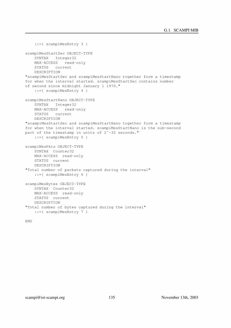
G.1. SCAMPI MIB
::={ scampiMesEntry 3 }
scampiMesStartSec OBJECT-TYPESYNTAX Integer32MAX-ACCESS read-onlySTATUS currentDESCRIPTION
"scampiMesStartSec and scampiMesStartNano together form a timestampfor when the interval started. scampiMesStartSec contains numberof second since midnight January 1 1970."
::={ scampiMesEntry 4 }
scampiMesStartNano OBJECT-TYPESYNTAX Integer32MAX-ACCESS read-onlySTATUS currentDESCRIPTION
"scampiMesStartSec and scampiMesStartNano together form a timestampfor when the interval started. scampiMesStartNano is the sub-secondpart of the timestamp in units of 2ˆ-32 seconds."
::={ scampiMesEntry 5 }
scampiMesPkts OBJECT-TYPESYNTAX Counter32MAX-ACCESS read-onlySTATUS currentDESCRIPTION
"Total number of packets captured during the interval"::={ scampiMesEntry 6 }
scampiMesBytes OBJECT-TYPESYNTAX Counter32MAX-ACCESS read-onlySTATUS currentDESCRIPTION
"Total number of bytes captured during the interval"::={ scampiMesEntry 7 }
END
[email protected] 135 November 13th, 2003


Bibliography
[1] R. Bace and P. Mell. Intrusion Detection Systems. National Institute of Standards and Technology(NIST), Special Publication 800-31, 2001.
[2] Jay S. Bayne. Unleashing the power of networks. http://www.johnsoncontrols.com/ Meta-sys/articles/article7.htm.
[3] Matt Blaze, Joan Feigenbaum, John Ioannidis, and Angelos D. Keromytis. The KeyNote trust-management system version 2. Network Working Group, RFC 2704, September 1999.
[4] H. Bos and B. Samwel. Hokes/pokes: Lightweight resource sharing. In Proceedings of the thridInternational Conference on Embedded Software, 2003.
[5] Nevil Brownlee. Traffic Flow Measurement: Experiences with NeTraMet. RFC2123,http://www.rfc-editor.org/, March 1997.
[6] K. Claffy. Priorities and challenges in internet measurement simulation and analysis, 2003.
[7] Kimberly C. Claffy, Hans-Werner Braun, and George C. Polyzos. A parameterizable method-ology for internet traffic flow profiling. IEEE Journal of Selected Areas in Communications,13(8):1481–1494, 1995.
[8] Nick G. Duffield and Matthias Grossglauser. Trajectory sampling for direct traffic observation.In SIGCOMM, pages 271–282, 2000.
[9] David Antos et. al. Packet header matching in combo6 ipv6 router. Technical Report 2003,CESNET.
[10] G. Iannaccone, C. Diot, I. Graham, and N. McKeown. Monitoring very high speed links. In ACMInternet Measurement Workshop, 2001.
[11] Gianluca Insolvibile. Kernel korner: The linux socket filter: Sniffing bytes over the network. TheLinux Journal, 86, Jnune 2001.
[12] K claffy Joel Apisdorf, Kevin Thompson, and Rick Wilder. Oc3mon: flexible, affordable, highperformance statistics collection, 1996. http://www.nlanr.net/NA/Oc3mon/.
[13] Juniper. M5 and M10 Internet Routers Hardware Guide, 2002. http://www.juniper.net.
[14] Ken Keys, David Moore, Ryan Koga, Edouard Lagache, Michael Tesch, and k claffy. The archi-tecture of CoralReef: an Internet traffic monitoring software suite. In PAM2001 — A workshopon Passive and Active Measurements. RIPE NCC, April 2001.
137

BIBLIOGRAPHY
[15] E.P. Markatos. Tracing a large-scale peer to peer system: an hour in the life of gnutella. In Pro-ceedings of the CCGrid 2002: the second IEEE International Symposium on Cluster Computingand the Grid, May 2002.
[16] S. McCanne, C. Leres, and V. Jacobson. libpcap. Lawrence Berkeley Laboratory, Berkeley, CA,available via anonymous ftp to ftp.ee.lbl.gov.
[17] Steven McCanne and Van Jacobson. The BSD packet filter: A new architecture for user-levelpacket capture. In USENIX Winter, pages 259–270, 1993.
[18] Endance measurement systems. DAGH 4.2GE dual gigabit ethernet network interface card, 2002.
[19] David Moore, Geoffrey M. Voelker, and Stefan Savage. Inferring internet Denial-of-Service ac-tivity. In USENIX Security Symposium, pages 9–22, 2001.
[20] NET-SNMP. The net-snmp home page. http://www.net-snmp.org.
[21] Committee on Research Horiaons in Netwreking. Looking over the Fence at Networks: A Neigh-bor’s View of Networking Research. National Academy Press, 2001.
[22] P. Phaal, S. Panchen, and N. McKee. Inmon corporation’s sflow: A method for monitoring trafficin switched and routed networks, September 2001. IETF RFC 3176, Network Working Group.
[23] J. Quittek, T. Zseby, B. Claise, and S. Zander. Requirements for ip flow information export.Internet Draft, draft-ietf-ipfix-reqs-09.txt.
[24] J. Rajahalme, A. Conta Transwitch, B. Carpenter, and S. Deering. Ipv6 flow label specification,2002. IETF IPv6 Working Group, INTERNET-DRAFT draft-ietf-ipv6-flow-label-02.txt.
[25] D. M. Ritchie and K. Thompson. The UNIX time-sharing system. The Bell System TechnicalJournal, 57(6 (part 2)):1905+, 1978.
[26] Martin Roesch. Snort: Lightweight intrusion detection for networks. In Proceedings of the 1999USENIX LISA Systems Administration Conference, November 1999. (software available fromhttp://www.snort.org/).
[27] Oliver Spatscheck. How to monitor network traffic 5 gbit/sec at a time. In Workshop on Manage-ment and Processing of Data Streams, 2003.
[28] Cisco Systems. Netflow services and applications, 1998.http://www.cisco.com/warp/public/732/netflow/napps wp.htm.
[29] C. Taylor. Attack of the world wide worms. TIME, 2003.
[30] tcpdump. http://www.tcpdump.org/.
[31] N.C. Weaver. Warhol worms: The potential for very fast internet plagues. Technical report, 2002.
[email protected] 138 November 13th, 2003