information handout - california department of · pdf file ·...
TRANSCRIPT

FOR CONTRACT NO.: 11-294804 PROJECT ID: 1100020250
INFORMATION HANDOUT
AGREEMENTS
QUECHAN TRIBE (TRIBE) 1. TRIBAL EMPLOYMENT RIGHTS ORDINANCE (TERO) REQUIREMENTS:
1.1. MEMORANDUM OF UNDERSTANDING (MOU) WITH DISTRICT 11 1.2. TERO HIGHWAY CONSTRUCTION PERMIT (THCP) APPLICATION 1.3. TERO COMPLIANCE PLAN 1.4. TERO COMPLIANCE PLAN APPLICATION
2. TRIBAL PERMIT TO ENTER AND CONSTRUCT:
2.1. APPLICATION FOR BUSINESS PERMIT 2.2. WAIVER OF LIABILITY
MATERIALS INFORMATION
GEOTECHNICAL DESIGN REPORT FOR STATE ROUTE 186 ANDRADE BORDER CROSSING PEDESTRIAN PROJECT, DATED MARCH 12, 2013
ROUTE: 11-IMP-186, 0.0/0.4


Attachment A Project Fact Sheet Caltrans and Quechan Tribe MOU executed on April 29, 2013.
Project Fact Sheet The following State highway construction project(s) have TERO requirements that must be followed pursuant to the provisions in the MOU signed by the Quechan Tribe and Caltrans on April 29, 2013:
Project EA and Project
ID No.
County-Route-Postmile(s) of
project
Project Description
Bridge Number [if bridge work
included]
IRR Inventory
Postmiles for IHP
TERO fee Postmiles
1100020250 Imp-186,
0.0-.04
Pedestrian/Transit
Facilities
N/A SR-186, 0.00-2.13
Imp-186,
0.0-0.04
Contacts: Caltrans: Phone Numbers: District Director: Laurie Berman (619) 688-6668 DNAL: Gus Silva (619) 208-1104 Project Manager: Sam Amen (619) 718-7835 RE: Shawn Rizzutto (760) 355-0430 or Cell (760) 594-2032 Const. Inspector [if assigned]: Tribal Contacts: Phone Numbers: TERO Officer/Director: Melvin Miguel (760) 572-4274, ext. 231 Tribal Administrator: Brian Golding (760) 572-5270

TERO MOU Date: April 29, 2013
ATTACHMENT B TERO Highway Construction Permit (THCP)
Quechan Tribe Tribal Highway Construction Permit
P.O. Box 1899 Yuma, Arizona 85366-1899
Name of Project: Andrade Pedestrian/Transit Facilities-(TE)
Caltrans Project Expenditure Authorization (EA) Number: 294801
The Quechan Indian Tribe of Fort Yuma Indian Reservation , issues this permit in accordance with its Tribal Employment Rights Ordinance, enacted by the federally recognized governing body of the tribe, the Quechan Tribal Council. This permit sets forth the terms and conditions under which a Contractor [and Subcontractors] are authorized to conduct work on California Department of Transportation (Caltrans) projects that occur on Tribal Land.
Terms and Conditions:
1. Contractor/Employer: Within 5 days of contract approval, Contractor will file a Labor Force Projection Form (attached) with the Tribe’s TERO Officer. Contractor will describe the types of work to be preformed and skills needed to undertake such work. [Work to be performed by subcontractors will be included on [a/the] Labor Force Projection Form.]
2. Core Crew: Contractor [and Subcontractors] will identify key employees, generally supervisory in nature that have worked continuously for many seasons and are not recently hired for this specific project on the Labor Force Project form.
3. Indian Preference: If available, qualified Indians must be hired in preference to non-Indians. Employer shall neither recruit nor hire any non-Indians for any covered position until the tribal TERO Officer has provided notice that no qualified Indians are available to fill such covered position. The TERO Officer maintains an Indian Skills-Bank to assist Employers to meet the Indian preference requirements of the Tribal Employment Rights Ordinance. Covered positions are defined in the Ordinance. Each waiver issued is only for that particular position/task and the employee cannot be transferred to another position once that job is done.
4. Labor Force Changes and Curtailment: Contractor will inform the TERO Officer of any potential changes to a project that could impact the labor force while construction is ongoing. Potential changes could be the result of additional work being needed to complete a project, among other things. Where a reduction in force is necessary, excepting Core Crew members, Indians hired pursuant to Indian preference will have the priority in retention.

5. Compliance Inspections: The TERO Officer or other designated staff will make periodic visits to project sites to ensure employment and safety rules are adhered to. [The Officer will contact the Contractor and RE prior to site visits.] To facilitate the inspections, the Contractor will share work schedules, contact information, and information on safety or other meetings with the TERO Officer at the preconstruction meeting or other venues as arranged.
6. [Maintaining Employment Records: Contractors will maintain accurate employment records on all employees and all applicants for employment; regardless of length and category or employment, hired, fired, or laid-off. The files shall reflect: name, address and employment category for which applicant performed or applied to perform. If applicant was contacted but not hired, hired and fired, all data should reflect action taken by that firm. Such informational records shall be made available to the TERO Officer, upon reasonable notice.]
7. Assistance: If a Contractor deems that an Indian employee’s performance is such that he or she is jeopardizing and endangering job loss, suspension, or termination, the Contractor may contact the TERO Officer to provide assistance toward resolving of that issue.
8. [Tribal Holidays and Ceremonial Customs: It is further understood that the Contractor recognizes operations are taking place within a unique cultural setting. To the extent possible the Contractor, in consultation with the TERO Officer, should consider Tribal Holidays and ceremonial customs and accommodate Indian employees requesting certain leave of absences for religious purposes.]
9. Duration and Scope of Permit: This permit will terminate upon project completion but may be revoked by the TERO Officer in the case that the aforementioned conditions are not met. _____________________ _____________ Melvin Miguel TERO Director Date Quechan Tribe _____________________ _____________ Contractor Date

[
Labor Force Projection Form
This form must be completed and filed with the Quechan TERO Officer. Attach additional sheets if necessary.
Contractor/Subcontractor Name: Mailing Address: City, State, and Zip Code: Phone Number Cell # Contact: Contracting With: Caltrans Expenditure Authorization (EA): 294801
Briefly describe the project and basic tasks and types of work to be performed:
Please list types of skills and categories which will be required towards performing said contract:
1. 2. 3. 4. 5. 6. 7. 8. 9. 10. 11. 12. 13. 14. 15. 16. 17. 18. 19. 20. 21. 22. 23. 24. 25. 26.

Indian Preference shall be accorded at every Tier Level. Please list the names and positions of your Core Crew (Core Crew members are typically supervisory and members you depend on every day). All other persons needed on this job will go through the TERO Skills Bank.
Please use as many sheets as necessary for explaining your on-site employment related projection.
NAME JOB TITLE
1. 2. 3. 4. 5. 6. 7. 8. 9. 10. 11. 12. 13. 14. 15. 16.
_____________________ _____________ Contractor Date _____________________ _____________ Melvin Miguel TERO Director Date Quechan Tribe

State Contract 11-294804 Project ID 1100020250
Date April 29, 2013
ATTACHMENT C
Project-Specific Special Provisions For Quechan Tribe TERO MOU TERO Resolution Number R-100-13
SPECIAL NOTICE: This project includes Tribal Employment Rights Ordinance (TERO) requirements. See section
5-1.20E and 8-1.04C for TERO submittal requirements.
SSP 2-1.06B SUPPLEMENTAL PROJECT INFORMATION
The Department makes the following supplemental project information available:
Supplemental Project Information Means Description
Included in Information Handout 1. Quechan Tribe TERO Requirements: 1.1. Memorandum of Understanding (MOU) 1.2. TERO Highway Construction Permit (THCP)
Application. 1.3. Compliance Plan. 1.4. Compliance Plan Application.
INFORMATION HANDOUT: Quechan Tribe TERO MOU Information contains: 1. Signed one-time MOU between the Quechan Tribe and the Department. 2. Attachment A Project-Fact Sheet. 3. Attachment B TERO Highway Construction Permit Application (THCP). 4. Attachment C project-specific TERO special provisions. 5. Attachment D Scope of Memorandum.
SSP 5-1.20E Tribal Employment Rights Ordinance Requirements: Within 5 days after contract approval, apply to the Quechan Tribe (the Tribe) for a TERO Highway Construction Permit (THCP) and a TERO Compliance Plan using the forms in the Information Handout. Pay the Tribe a fee of $500.00 plus $500.00 per subcontractor with the TERO Compliance Plan application. Submit copies of these applications to the Engineer.
Submit copies of the executed TERO Compliance Plan and the THCP within 10 days after you receive them from the Tribe.
SSP 8-1.04C: Use a minimum 90-day delayed start after contract approval. Do not start job site activities until the Department authorizes or accepts your submittal for:
Executed Quechan Tribe TERO Highway Construction Permit (THCP) Executed Quechan Tribal TERO Compliance Plan Application Do not start other job site activities until all the submittals from the above list are authorized or accepted and the following information is received by the Engineer:
Copy of the executed Quechan Tribe TERO Highway Construction Permit (THCP). Copy of the executed Quechan Tribe TERO Compliance Plan Application.

Attachment D Scope of Memorandum Caltrans and Quechan Tribe MOU executed on April 29, 2013.
Scope of Memorandum
Projects within the following areas have TERO requirements that must be followed pursuant to the provisions in the MOU signed by the Quechan Tribe and Caltrans on April 29, 2013:
County Route Begin
Postmile End Postmile Assessor’s
Parcel Number (APN)
Tribal Land Ownership
Status
Imperial 186 0.0 0.4 Reservation

TERO MOU Date: April 29, 2013
ATTACHMENT B TERO Highway Construction Permit (THCP)
Quechan Tribe Tribal Highway Construction Permit
P.O. Box 1899 Yuma, Arizona 85366-1899
Name of Project: Andrade Pedestrian/Transit Facilities-(TE)
Caltrans Project Expenditure Authorization (EA) Number: 294801
The Quechan Indian Tribe of Fort Yuma Indian Reservation , issues this permit in accordance with its Tribal Employment Rights Ordinance, enacted by the federally recognized governing body of the tribe, the Quechan Tribal Council. This permit sets forth the terms and conditions under which a Contractor [and Subcontractors] are authorized to conduct work on California Department of Transportation (Caltrans) projects that occur on Tribal Land.
Terms and Conditions:
1. Contractor/Employer: Within 5 days of contract approval, Contractor will file a Labor Force Projection Form (attached) with the Tribe’s TERO Officer. Contractor will describe the types of work to be preformed and skills needed to undertake such work. [Work to be performed by subcontractors will be included on [a/the] Labor Force Projection Form.]
2. Core Crew: Contractor [and Subcontractors] will identify key employees, generally supervisory in nature that have worked continuously for many seasons and are not recently hired for this specific project on the Labor Force Project form.
3. Indian Preference: If available, qualified Indians must be hired in preference to non-Indians. Employer shall neither recruit nor hire any non-Indians for any covered position until the tribal TERO Officer has provided notice that no qualified Indians are available to fill such covered position. The TERO Officer maintains an Indian Skills-Bank to assist Employers to meet the Indian preference requirements of the Tribal Employment Rights Ordinance. Covered positions are defined in the Ordinance. Each waiver issued is only for that particular position/task and the employee cannot be transferred to another position once that job is done.
4. Labor Force Changes and Curtailment: Contractor will inform the TERO Officer of any potential changes to a project that could impact the labor force while construction is ongoing. Potential changes could be the result of additional work being needed to complete a project, among other things. Where a reduction in force is necessary, excepting Core Crew members, Indians hired pursuant to Indian preference will have the priority in retention.

5. Compliance Inspections: The TERO Officer or other designated staff will make periodic visits to project sites to ensure employment and safety rules are adhered to. [The Officer will contact the Contractor and RE prior to site visits.] To facilitate the inspections, the Contractor will share work schedules, contact information, and information on safety or other meetings with the TERO Officer at the preconstruction meeting or other venues as arranged.
6. [Maintaining Employment Records: Contractors will maintain accurate employment records on all employees and all applicants for employment; regardless of length and category or employment, hired, fired, or laid-off. The files shall reflect: name, address and employment category for which applicant performed or applied to perform. If applicant was contacted but not hired, hired and fired, all data should reflect action taken by that firm. Such informational records shall be made available to the TERO Officer, upon reasonable notice.]
7. Assistance: If a Contractor deems that an Indian employee’s performance is such that he or she is jeopardizing and endangering job loss, suspension, or termination, the Contractor may contact the TERO Officer to provide assistance toward resolving of that issue.
8. [Tribal Holidays and Ceremonial Customs: It is further understood that the Contractor recognizes operations are taking place within a unique cultural setting. To the extent possible the Contractor, in consultation with the TERO Officer, should consider Tribal Holidays and ceremonial customs and accommodate Indian employees requesting certain leave of absences for religious purposes.]
9. Duration and Scope of Permit: This permit will terminate upon project completion but may be revoked by the TERO Officer in the case that the aforementioned conditions are not met. _____________________ _____________ Melvin Miguel TERO Director Date Quechan Tribe _____________________ _____________ Contractor Date

[
Labor Force Projection Form
This form must be completed and filed with the Quechan TERO Officer. Attach additional sheets if necessary.
Contractor/Subcontractor Name: Mailing Address: City, State, and Zip Code: Phone Number Cell # Contact: Contracting With: Caltrans Expenditure Authorization (EA): 294801
Briefly describe the project and basic tasks and types of work to be performed:
Please list types of skills and categories which will be required towards performing said contract:
1. 2. 3. 4. 5. 6. 7. 8. 9. 10. 11. 12. 13. 14. 15. 16. 17. 18. 19. 20. 21. 22. 23. 24. 25. 26.

Indian Preference shall be accorded at every Tier Level. Please list the names and positions of your Core Crew (Core Crew members are typically supervisory and members you depend on every day). All other persons needed on this job will go through the TERO Skills Bank.
Please use as many sheets as necessary for explaining your on-site employment related projection.
NAME JOB TITLE
1. 2. 3. 4. 5. 6. 7. 8. 9. 10. 11. 12. 13. 14. 15. 16.
_____________________ _____________ Contractor Date _____________________ _____________ Melvin Miguel TERO Director Date Quechan Tribe

COMPLIANCE PLAN
Melvin Miguel, TERO Director
P.O. Box 1899
Yuma, Arizona 85366
(760) 572-0213, ext 231 Office
(760) 572-4274 Fax
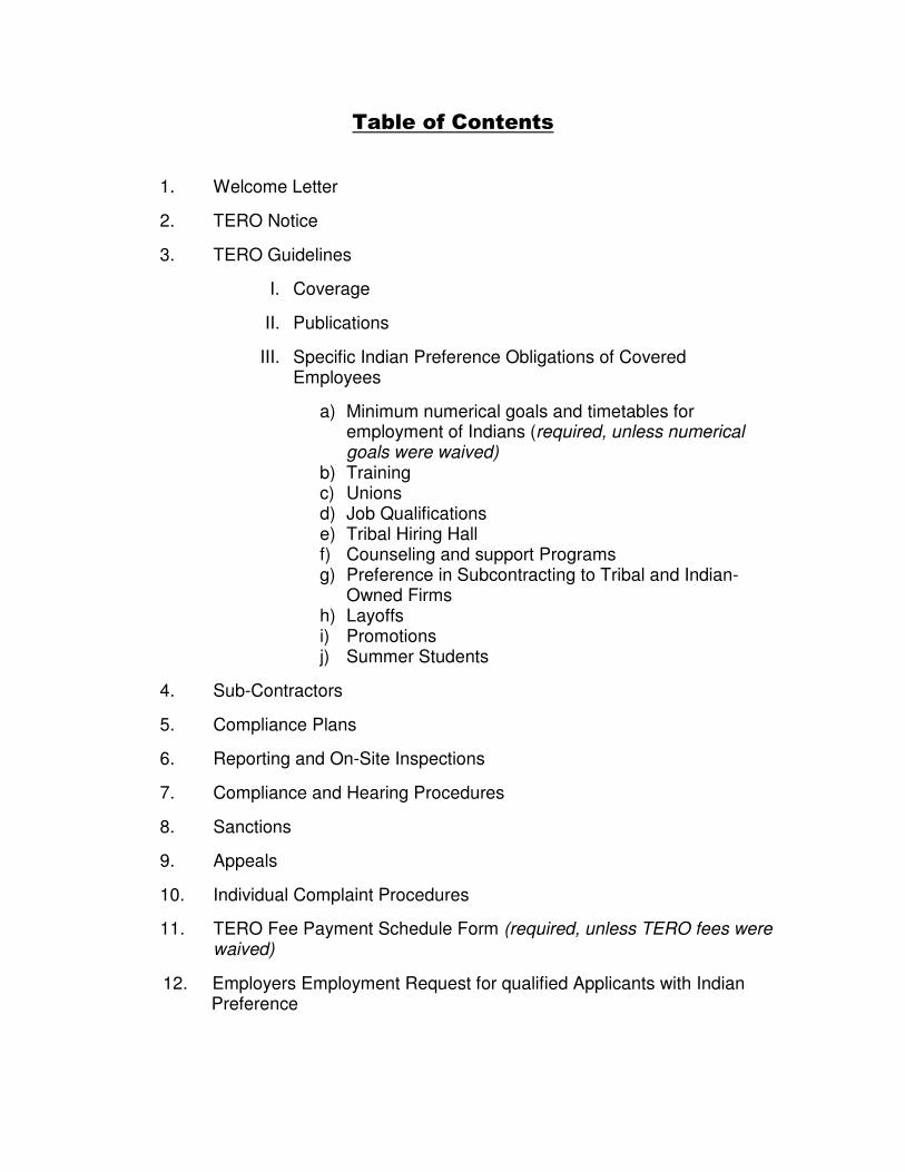
Table of Contents
1. Welcome Letter
2. TERO Notice
3. TERO Guidelines
I. Coverage
II. Publications
III. Specific Indian Preference Obligations of Covered Employees
a) Minimum numerical goals and timetables for employment of Indians (required, unless numerical goals were waived)
b) Training c) Unions d) Job Qualifications e) Tribal Hiring Hall f) Counseling and support Programs g) Preference in Subcontracting to Tribal and Indian-
Owned Firms h) Layoffs i) Promotions j) Summer Students
4. Sub-Contractors
5. Compliance Plans
6. Reporting and On-Site Inspections
7. Compliance and Hearing Procedures
8. Sanctions
9. Appeals
10. Individual Complaint Procedures
11. TERO Fee Payment Schedule Form (required, unless TERO fees were waived)
12. Employers Employment Request for qualified Applicants with Indian Preference

QUECHAN INDIAN TRIBE
Ft. Yuma Indian Reservation
P.O. Box 1899
Yuma, Arizona 85366-1899
Phone (760) 572-0213 x231
Fax (760) 572-4274
Welcome!
The Tribal Employment Rights Office (TERO) is the central reference point for all private employment on the FT. Yuma Indian Reservation.
We assist individuals in all phases of the employment process. This includes assisting employers in locating qualified Quechan men and women. We advertise positions; prescreen applicants to meet the specific needs of the employers. We require that all employers contact our office for all their employment needs. Your specific job requirements will be matched with individual qualifications.
The individual and/or the employer will be issued a referral slip as proof that he/she has been prescreened and meets your requirements.
We request that you hire only those individuals who have been issued a referral slip from the TERO. (attachment a)
To enable the TERO to effectively execute its duties and to provide you with assistance, we request the following information prior to commencing work on the FT. Yuma Indian Reservation:
1) The prime company contractor for this project including a list of all Subcontractors/or suppliers, if any; types of work to be performed, and the key employees by name, title and duration of individuals needed for this project. 2) A list of employment needs, approximate number and type(s) of workforce needed, i.e., Construction Laborers; Crane Operators, etc. 3) Bona fide minimum occupational requirements to fill a position. 4) Approximate start date, duration of work and a bar chart of scheduled work. 5) After commencement of work, certified payroll records are to be submitted on a weekly basis.
This Compliance Plan is required prior to commencing any work of the Quechan Reservation.
Failure to provide this data will only generate uncertainty and confusion for all parties involved. The TERO will monitor this project and will be available to assist you in meeting your employment obligations.
We would appreciate your promptness in providing this information and hope your business on the Fort Yuma Indian Reservation is both enjoyable and profitable.
Respectfully, Melvin Miguel, Director Tribal Rights Employment Office

QUECHAN INDIAN TRIBE Ft. Yuma Indian Reservation
P.O. Box 1899 Yuma, Arizona 85366-1899
Phone (760) 572-0213, ext 231 Fax (760) 572-4274
TERO NOTICE
TO: All contractors, subcontractors, employers, and contract award
agencies located or engaging in commercial business or employment
activity on the Fort Yuma Indian Reservation.
NOTICE IS HEREBY GIVEN that the Quechan Indian Tribe has a Tribal
Employment Rights Ordinance (TERO) in effect which requires Indian
preference in all construction employment, other employment, training
and contracting on Fort Yuma Indian Reservation.
BE ADVISED that the Ordinance requires one-half of one percent (0.5%)
of the total contract award as the Employment Administration fee on
each employment contract performed on the Reservation, unless the fee
has been waived by Tribal Council.
All contractors and/or subcontractors are urged to contact the Quechan
TERO Office for full information prior to bidding or performing work on
the Reservation.
Contact: Melvin Miguel, TERO Director P.O. Box 1899 Yuma, AZ 85366-1899
NOTE: Any contractor or subcontractor not submitting a Compliance
Plan Agreement will be denied the right to commence work or continue
any work in progress until said Plan is submitted, reviewed and approved
by the TERO Officer.

TERO GUIDELINES
The following guidelines are issued pursuant to the authority granted to the Quechan Tribal Employment Rights Office hereinafter called the “Office” by Tribal Resolution R-23-79, which requires preferential employment of Indians by all employers operating within the exterior boundaries of the Quechan Reservation.
1. COVERAGE:
The guidelines shall be binding on all existing and future employers within the exterior boundaries of the Quechan Reservation, hereinafter called “the Reservation”. “Employer” means any person, company, contractor, sub-contractor or other entity that is located or otherwise engaged in work on the Reservation, and that employs five or more persons. The term “Employer” does not include Federal, State, County, or other governmental agencies. It does include contractor or sub-contractor of a governmental company, if at least five of its employees spend a majority of their time performing work within the exterior boundaries of the Reservation on a continuing basis. If an employer is engaged in work of the Reservation, these guidelines shall also apply to any other facilities of the employer that are located within the reasonable commuting distance from the Reservation. Where covered employer has already agreed, in contract or other document, to give preference to Indians, these guidelines shall define the specific obligations of that employer assumed in such agreement. The Office, reserves the right to phase in the requirements set out in these guidelines by first applying them to select types of employers. For example, the Office may determine if it’s appropriate to apply them only to construction contractors during the first period of the employers operation.
2. PUBLICATIONS
The obligation of all employers to comply with Trial Employment Rights requirements shall be made known to all existing and future employers. All bid announcements issued by any Tribal, Federal, State or other private or public agency will be obligated to comply with these guidelines and that a bidder may contact this office to obtain additional information. Those agencies responsible for issuing business permits for the Reservation or otherwise engaged in activities involving contact with prospective employers on the Reservation shall be responsible

for informing such prospective employers of their obligations under these guidelines. Within one month of the effective date of these guidelines, the Office shall send copies of the guidelines to every employer presently operating on the Reservation. It shall be the responsibility of the Office to send copies of any amendments or revisions of the guidelines to all covered employers.
3. SPECIFIC INDIAN PREFERNCE OBLIGATIONS OF COVERED
EMPLOYERS: a. Minimum numerical goals and timetables for the employment of
Indians. The Office, will establish the minimum number of Indian person that
each employer must employ on its work force during any year that its employees work on the Reservation, in order for that employers to be in compliance with its Indian Preference obligations. If agreed upon, numerical goals shall be set for each craft, skill area, job classification, etc. used by the employer and shall include administrative, supervisory and professional categories. The goals shall be expressed in terms of man-hours of Indian employment as a percentage of the total man-hours worked on the employer’s work force in that classification. (e.g., no less than 50% of all carpenter man-hours shall be worked by Indian carpenters). The goals shall be realistic and shall be based on surveys of the available Indian man-hour pool and of projected employment opportunities.
For new employers, the goals shall be established for the entire
work force. The employer shall meet with the Office as much before it actually begins work as is possible e.g., immediately after a bid is accepted and a contract signed. The employer shall provide the Office with a precise list of number and kinds of employees it projects it will need. The Office shall then set specific goals and timelines for that employer after considering any special factors or circumstances that the employer wishes to present. The employers shall incorporate the goals into its plan for complying with the guidelines (as provided in paragraph 5 of these guidelines), and shall agree in writing to meet these goals. An employer who fails to provide such a written statement will not be permitted to commence work on the Reservation. For existing employers on the Reservation, the goals shall be a percentage of the new employees projected to be employed during the forthcoming year by that employer. The employer shall agree to said goals in writing and they shall be incorporated into the Plan provided for in paragraph 5 of these guidelines.
Each employer shall meet its minimum goals for the employment of Indians or shall demonstrate that it has made a best effort to meet

its goals. The Office shall have the right to issue a notice of non-compliance any time during the year, when based on reports submitted by the employer is not meeting, or is not making good faith effort to meet its goals. Upon receipt of such notice, an employer shall be entitled to a hearing as provided for in paragraph 7 of these guidelines.
The burden shall then shift to the employer to demonstrate that an employer has failed or is failing to meet its goals. The employer must demonstrate that it made a best effort to meet its goals. It shall be no excuse that the Union(s) with which the employer has a collective bargaining agreement providing for exclusive referral, failed to refer Indians. An employer who is found to be out of compliance because it failed or is failing to meet its goals, and who is unable to demonstrate that it made a best effort to do so shall be subjected to the sanctions provided for in paragraph 5 of these guidelines. b. Training All employers, as requested by the Office, shall participate in training programs to assist Indians become more qualified in the various job classifications used by the employer. Employers engaged in construction shall employ the maximum number of trainees or apprentices possible. The ratio of trainees to fully qualified workers shall be set by the Office after discussions with the employer. For construction projects, the number shall be no less than the minimum ratio established by the Department of Labor and generally shall be greater. All trainees or apprentices shall be Indian. Where an employer is not presently participating in a Union Apprenticeship Program, the Tribe shall make a best effort to bear the cost of such training programs but employers may be required to also bear part of the costs. Employers with collective bargaining agreements with the Unions shall be required to obtain agreement from the Unions to agree to establish advanced apprenticeship and journeyman upgrade programs.
c. Unions
Employers with collective bargaining agreements shall be required to obtain written agreement from all signatory unions, stating the Union will comply with the Tribe’s Indian Preference requirements, before the employer will be permitted to commence work on the Reservation. Such agreement shall be subject to the approval of the Office. The Union must agree to give absolute preference to Indians in referral, regardless of which Union referral list they are on; to cooperate with the Tribal Hiring Hall; and to establish mechanisms so that Indians do not have to travel great distances

on a regular basis, to retain their place on the Union lists (this would involve phone or mail registration, or a Union sub-office on the Reservation); to establish journeyman upgrade and advanced apprenticeship programs; to indenture and refer only Indian apprentices to the Employer; to blanket into the Union all Indians who qualify for journeyman status and who wish to join the Union; to grant temporary work permits to Indian who do not wish to join the Union; and to meet such other requirements as the Office may deem necessary to carry the Tribe’s Indian preference program.
The Office’s participation in written agreement with a Union in no way constitutes official tribal recognition of the Union or tribal endorsement of any recruiting activities conducted by the Union.
d. Job Qualifications and Personnel Requirements:
An employer may use no job qualification criteria or personnel requirements which serves as a barrier to the employment of Indians and which is not required by business necessity. The burden shall be on the Office to demonstrate that a criteria or personnel requirement is a barrier to the Indian employment. The burden will then be on the Employer to demonstrate that such criteria or requirement is required by business necessity. If the employer fails to meet this burden, he will be required to eliminate the criteria or personnel requirement at issue. Employers shall also make reasonable accommodation to the religious beliefs of Indian workers in implementing these requirements; the Office shall be guided by the principles established by the EEOC guidelines, particularly 29 CFR Parts 1604 through 1607. However, the Office retains the rights to go beyond the EEOC principles in order to address employment barriers that are unique to Indians.
Where the Office and employer are unable to reach an agreement on the matters covered in this paragraph, a hearing, as provided for in paragraph 7 shall be held. The Director shall make a determination on the issues and shall order such actions as he deems necessary to bring the employer into compliance with the paragraph. The employer may appeal the decision under the procedure provided for in paragraph 9.
e. Tribal Hiring Hall:
The employer may recruit and hire workers from whatever sources are available to him and by whatever process he so chooses, provided that he may not hire a non-Indian until he has given the Office a reasonable time to locate a qualified Indian. For the purpose of this section “reasonable time” shall be defined as follows: For construction jobs, the Office shall have 48 hours to

locate and an additional 12 hours to refer a qualified Indian; for all other kinds of employment, the Office shall have five working days. However, the Office shall consider waivers of these time periods upon showing by the employer that such time periods impose an undue burden on the employer. An employer with collective bargaining agreements with a Union(s) shall not be required to follow this procedure if the Unions agree to place on their referral lists all names that are called into them by the Office (see model union agreement). However, if a Union fails to meet its obligations to refer Indians, the Office reserves the right to require the employer to accept Indian referrals from sources other than the Union.
Any non-Indian worker found to be employed in a job which has not first cleared through this hiring hall procedure shall be subject to summary removal from the job by the Office and the employer shall be subject to a fine of $500.00 for each violation except that the employer is entitled to a hearing and appeal in accordance with provisions of paragraph 7 and 9 of the guidelines. f. Counseling and Support Programs The Office, in conjunction with other Tribal and Federal Offices, will provide counseling and other support services to Indians employed by covered employers to assist such Indian retain employment. Employers shall be required to cooperate with such counseling and support services. g. Preference in Subcontracting to Tribal and Indian-Owned Firms: Employers shall give reference in the award of sub-contracts to tribally-owned and other Indian-owned firms and enterprises. An Indian-owned firm is one that has qualified as such under the BIA Self-Determination regulations. The Office shall maintain a list of such firms and the employer shall make use of said list. Employers shall not be required to take any extra ordinary measure on their own to identify or locate Indian-owned Enterprises. h. Layoffs: In all layoffs and reductions-in-force, no Indian worker shall be terminated if a non-Indian in the same craft is still employed. The non-Indian shall be terminated first so long as there are non-Indians in the same craft employed elsewhere on the job-site.
i. Promotions: The employer shall give Indians preferential consideration for all promotion opportunities and shall encourage Indians to seek such opportunities. For all supervisory positions filled by non-Indians, the employer shall file a report with the Office stating what Indians, if any, applied for the job, the reasons why they were not given the job, and what efforts were made to inform Indian workers about the opportunity. j. Summer Students: Indians shall be given preference in the hiring of summer student help. The employer shall make every effort to promote after-school, summer and vacation employment for Indian youth.
4. SUB-CONTRACTORS
The Indian preference requirements contained in these guidelines shall be binding on all sub-contractors of covered employers, regardless of their Tier, and shall be deemed a part of all resulting subcontract specifications. The employer shall have the initial and primary responsibility for insuring that all sub-contractors comply with these requirements and the Office reserves the right to impose sanctions on the employer, as well as on the sub-contractor, if sub-contractor fails to comply.
5. COMPLIANCE PLANS
From the effective date of these guidelines, no new employer may commence work on the Reservation until it has met with this Office and develop an acceptable plan for meeting its obligations under these guidelines.
6. REPORTING AND ON-SITE INSPECTIONS 7. COMPLIANCE AND HEARING PROCEDURE:
If the Director of the Office believes that an employer (including a sub-contractor) has failed to comply with any of these requirements set out in these guidelines, he or she shall so notify the employer in writing specifying in detail the alleged violation(s). The employers shall then be entitled to a hearing before the Director. Hearing procedures shall comply with the requirements of due process but will not be bound by the formal rules of evidence. The employer

shall be entitled to present evidence and to call witnesses to demonstrate that the employer has complied with the requirements of these guidelines or that the employer made a best effort to do so and therefore should not be subject to sanctions. The Director shall have the right to subpoena witnesses and documents, to put witnesses under oath, to call witnesses and present evidence in the Tribe’s behalf, and to take such other steps as are necessary to insure a fair and complete hearing on the issues. On the basis of evidence presented at the hearing and the information collected by the Office, the director shall determine whether or not the employer(s) complied with its Indian Preference requirements.
If the Director determines that the employer is out of compliance and has not made a best effort to comply, the Director shall impose one or more of the sanctions provided for in paragraph 8 of these guidelines, as appropriate, and shall order the employer to take such corrective action as is necessary to remedy any harm done to the tribe or to individual Indians by the employer’s non-compliance. The Director shall send written notice of the decision to the employer.
8. SANCTIONS:
In the event that an employer is found to be out of compliance with the requirements of these guidelines, the Director shall be entitled to impose any or all of the following sanctions, as appropriate, after considering such mitigating factors as the employer’s effort to comply and its effort to remedy any harm done by its non-compliance.
a. Impose monetary fines b. Suspend the employer’s operation until corrective action is taken or a plan for corrective action is developed c. Terminate the employer’s operation d. Prohibit the employer from engaging in any future operations on the Reservation e. Require the employer to remove certain workers and/or to hire certain workers f. Provide back pay, employment, promotion, training and/or other relief to Indians who were harmed by the employer’s non-compliance. g. Require the employer to make such changes in its procedures as is necessary in order to comply with these requirements.

9. APPEALS:
The employer shall have the right to appeal any decision of the Director to the Quechan Tribal President. An appeal must be filed within twenty (20) days after receipt of notice of the Director’s decision. The Director shall represent the interest of the Tribe during the appeal.
10. INDIVIDUAL COMPLIANT PROCEDURE:
Any Indian, group of Indians, or representatives of a class of Indians who believe that an employer has failed to comply with these guidelines or who believe that they have been discriminated against by a covered employer because they are Indian, may file a complaint with the Office. Persons may file whether or not they can show that they were personally harmed by the employer’s non-compliance. Upon receipt of a complaint the Office shall conduct an investigation of the charge and shall attempt to achieve an informal settlement of the matter. If voluntary conciliation cannot be achieved, the Director shall hold a hearing on the matter, shall make a determination on the validity of the charge, and shall order such relief as is necessary to make whole an Indian who was harmed by the employer’s non-compliance if discriminatory behavior.
The decision shall be in writing and shall be sent to all parties. Either part shall have the right to appeal the decision of the Director to the Tribal Court as provided for in paragraph 9. Such appeal must be filed within twenty (20) days after receipt of the decision notice from the Director. In conducting the hearing provided for in this paragraph, the Director shall have the same powers, and shall be bound by the same requirements, as those set out in regards to the hearing provided for in paragraph 7 of these guidelines.
T.E.R.O.
QUECHAN INDIAN TRIBE
TRIBAL EMPLOYMENT RIGHTS OFFICE
COMPLIANCE PLAN CONDITIONS
COMPANY:______________________________________
PROJECT:_______________________________________
TRIBAL BUSINESS PERMIT:_______________________
DATE: _________________________________________

ANY EMPLOYER NOT SUBMITTING AN ACCEPTABLE COMPLIANCE PLAN
MAY BE DENIED THE RIGHT TO COMMENCE OR CONTINUE DOING
BUSINESS ON THE FT YUMA INDIAN RESERVATION
Ordinance Given: ( ) Yes ( ) No Given on Prior Project TERO Fee Payment Schedule is (0.5) of 1% of overall contract award. Date:_________N/A______________Date:___________N/A________________ Date:_________N/A______________Date:___________N/A________________ Notes: __Payment of the TERO Fee for project 11-294801 is covered by the _________ __Memorandum of Understanding (MOU) between the California Departement of __Transportation (Caltrans) and The Quechan Tribe of the Fort Yuma Indian___ __Reservation. Caltrans will pay the TERO Fee directly to the Tribe.__________ Please state your Sub-contractor Plan showing documentation that Indian Preference has been addressed as per this Project: List the identified Indian Preference Sub-contractors for this Project: Company Area of Work Contact Person(s) ________________________________________________________________ ________________________________________________________________ ________________________________________________________________ ________________________________________________________________ I have read the TERO COMPLIANCE PLAN AGREEMENT and agree to abide by the stated conditions: Employer’s Signature: _________________________________ Date: ________________ TERO Official Signature: _________________________________ Date: ________________

Contract Amount: _____N/A________ TERO Fee @ ½ of 1% (N/A) Company: ___________________ Project: _________________________ Supt.: _______________________ Phone: _________________________ Mailing Address: ________________________________________________________________ ________________________________________________________________ ________________________________________________________________ Project Start Date: _______________ Project End Date: _________________ CORE CREW DEFINITION: A member of a contractor’s or subcontractors crew who is a regular, permanent employee and is in a supervisor or other key position such that the employer would face a serious financial loss if that position were filled by a person who had not previously worked for that employer. Core Crew – Name Job Classification __________________________ ________________________________ __________________________ ________________________________ __________________________ ________________________________ __________________________ ________________________________ __________________________ ________________________________ ESTIMATED NUMBER OF WORKERS NEEDED AND JOB TITLES: ________________________________________________________________
________________________________________________________________
________________________________________________________________
________________________________________________________________
________________________________________________________________
________________________________________________________________
________________________________________________________________
Employer’s Signature: _________________________________ Date: ________________ TERO Official Signature: _________________________________ Date: ________________

TRIBAL EMPLOYMENT RIGHTS OFFICER
REFERRAL SLIP
Date:
To:
From: Melvin Miguel, T.E.R.O.
Project:
Per Contractors request, the following skill/trades are requested: (#TERO USE ONLY)
______________________________________________________________________
PERSON BEING REFFERED:
Name: Telephone #:
Date & Time Contact Made By TERO:
*****TERO USE ONLY******
Quechen Tribal Member Enrollment Number: ________N/A______________________
Other Tribal Member Enrollment Number: ____________________________________
Tribe Name: ______________________________________________________
Non-Tribal Member:_________(Supporter of an Indian family, i.e. Spouse or children)
Date of Hire:________________Rate of Pay: Salary:_______Hourly:_________
Job Site:________________________________________________________________
Tools (if applicable):_______________________________________________________
On-The-Job-Training: Yes___ No___
Reason if not hired:________________________________________________________
________________________________________________________________________
________________________________________________________________________

CONTRACTORS EMPLOYMENT REQUEST
FOR QUALIFIED APPLICANTS
WITH INDIAN PREFERENCE
FAX MEMORANDUM (760) 572-4274
Date of Request: _______________________________________________
From: _______________________________________________________
Project: ______________________________________________________
To: Mr. Melvin Miguel, TERO
1. Request referrals for the following skills and/or trades necessary to
complete the above mentioned project.
a. _______________________________________________
b. _______________________________________________
c. _______________________________________________
d. _______________________________________________
e. ________________________________________________
2. If you have any questions, please contact _________________________.

QUECHAN INDIAN TRIBE Fort Yuma Indian Reservation
P. O. Box 1899 YUMA, ARIZONA 85366-1899
Phone (760) 572-0213 FAX (760) 572-0519
ATTN: Brandy Cachora, EDA Assistant Planner
BUSINESS PERMIT APPLICATION
CONTRACTING FIRM/BUSINESS NAME: CURRENT DRIVERS LICENSE NO. AND CLASS: FEDERAL EMPLOYER/TAX PAYER I. D. NUMBER:
BUSINESS ADDRESS: PHONE:
FAX: MAILING ADDRESS:
FULL DESCRIPTION OF BUSINESS ACTIVITY: OWNER / PARTNERS OR CORPORATE OFFICERS: ADDRESS: ADDRESS: ADDRESS: BY AFFIXING SIGNATURE BELOW, WE AGREE TO ABIDE BY TRIBAL RESOLUTION R-23-79 (T. E. R. O. RESOLUTION) AND ORDINANCE QT-02-94, (TRIBAL LICENSE FEES AND TAXES) AND ANY OTHER APPLICABLE TRIBAL ORDINANCES. SIGNED: TITLE: DATE:
FOR OFFICE USE ONLY FEES: CHECK NO. CASH RECEIPT NO. RECEIVED BY: EXPIRATION DATE:

QUECHAN INDIAN TRIBE Fort Yuma Indian Reservation
P. O. Box 1899 YUMA, ARIZONA 85366-1899
Phone (760) 572-0213 FAX (760) 572-0519
WAIVER OF LIABILITY
The undersigned hereby agrees to waive any and all claims against the Quechan Indian Tribe and its employees or agents for any theft, damages, or injuries that are a result of the operation of any business, vending or other company, having been issued a business permit from the Quechan Indian Tribe to operate such business within the exterior boundaries of the Fort Yuma Indian Reservation.
The undersigned seeks to become licensed and permitted pursuant to the Code of Federal Regulations (CFR) 25 Section 251 and Article IV, Section 6, of the Constitution and Bylaws of the Quechan Indian Tribe of the Fort Yuma Indian Reservation.
The Quechan Indian Tribe shall declare this waiver null and void at the date of expiration of the permit.
Having read and fully understand this waiver, as owner or authorizing signature and witness, I hereby agree to the terms and conditions as stated in the above recitals.
Owner / Authorizing Signature
Dated this Day of 2013
Witness
Dated this Day of 2013

GEOTECHNICAL DESIGN REPORT
State Route 186 Andrade Border Crossing Pedestrian Project
11-IMP-186 /PM 0.0/0.4
EA 11-294801 EFIS 1100020250
March 12, 2013
Prepared By:
OFFICE OF GEOTECHNICAL DESIGN-SOUTH 2, BRANCH-D 7177 OPPORTUNITY ROAD
SAN DIEGO, CA 92111


March 12, 2013 Geotechnical Design Report State Route 186 Andrade Border Crossing Pedestrian Project EA 11-294801/EFIS 1100020250
iii
CARBON COPY (CC) LIST
Art Padilla District Materials Engineer
Abbas Abghari Office Chief, OGDS2
Shawn Wei Senior, OGDS2
Catalina Flores District 11 Landscape Architecture
http://svgcgeodog.dot.ca.gov/ Geotechnical Archive
[email protected] Structure Construction R.E. Pending File
OGDS2 File Room 7177 Opportunity Road, San Diego, CA 92111

March 12, 2013 Geotechnical Design Report State Route 186 Andrade Border Crossing Pedestrian Project EA 11-294801/EFIS 1100020250
iv
TABLE OF CONTENTS
Section Page
Title Sheet ...................................................................................................................................................... i Letter of Transmittal ..................................................................................................................................... ii Carbon Copy List ......................................................................................................................................... iii Table of Contents ......................................................................................................................................... iv List of Figures .............................................................................................................................................. vi List of Tables ............................................................................................................................................... vi List of Appendices ....................................................................................................................................... vi
1.0 INTRODUCTION ........................................................................................................................... 1
2.0 EXISTING FACILITIES AND PROPOSED IMPROVEMENTS ................................................. 1 2.1 Existing Facilities ............................................................................................................... 2 2.2 Proposed Improvements ..................................................................................................... 2
3.0 PERTINENT REPORTS AND INVESTIGATIONS ...................................................................... 3
4.0 PHYSICAL SETTING .................................................................................................................... 3 4.1 Climate ................................................................................................................................ 3 4.2 Topography & Drainage ..................................................................................................... 3 4.3 Man-Made and Natural Features of Engineering and Construction Significance .............. 3 4.4 Regional Geology and Seismicity ....................................................................................... 4 4.5 Soil Survey Mapping .......................................................................................................... 4
5.0 EXPLORATION ............................................................................................................................. 4 5.1 Drilling and Sampling ......................................................................................................... 4 5.2 Geologic Mapping .............................................................................................................. 4 5.3 Geophysical Studies ............................................................................................................ 5 5.4 Instrumentation ................................................................................................................... 5 5.5 Exploration Notes ............................................................................................................... 5
6.0 GEOTECHNICAL TESTING ......................................................................................................... 5 6.1 In Situ Testing ..................................................................................................................... 5 6.2 Laboratory Testing .............................................................................................................. 5
7.0 GEOTECHNICAL CONDITIONS ................................................................................................. 5 7.1 Site Geology ....................................................................................................................... 5
7.1.1 Lithology ................................................................................................................ 5 7.1.2 Structure ................................................................................................................. 6 7.1.3 Existing Slope Stability ......................................................................................... 6
7.2 Subsurface Conditions ........................................................................................................ 6 7.2.1 Soil ......................................................................................................................... 6 7.2.2 Groundwater .......................................................................................................... 6 7.2.3 Corrosion ............................................................................................................... 6
7.3 Surface Water ..................................................................................................................... 7 7.3.1 Scour ...................................................................................................................... 7 7.3.2 Erosion ................................................................................................................... 7 7.3.3 Tsunamis ................................................................................................................ 7
7.4 Site Seismicity .................................................................................................................... 7

March 12, 2013 Geotechnical Design Report State Route 186 Andrade Border Crossing Pedestrian Project EA 11-294801/EFIS 1100020250
v
TABLE OF CONTENTS (continued)
Section Page
8.0 GEOTECHNICAL ANALYSIS AND DESIGN ............................................................................. 7 8.1 Dynamic Analysis ............................................................................................................... 7 8.2 Liquefaction Analysis ......................................................................................................... 8 8.3 Cuts and Excavations .......................................................................................................... 8
8.3.1 Stability .................................................................................................................. 8 8.3.2 Rippability ............................................................................................................. 8 8.3.3 Grading Factors...................................................................................................... 8
8.4 Embankments ...................................................................................................................... 9 8.5 Retaining Wall-1 ................................................................................................................. 9 8.6 Culvert Foundations ............................................................................................................ 9 8.7 Soundwall Foundations ....................................................................................................... 9 8.8 Overhead Sign Foundations ................................................................................................ 9 8.9 Barrier Foundations ............................................................................................................ 9 8.10 Electrolier Foundations ....................................................................................................... 9 8.11 Shade Structure Foundations .............................................................................................. 9 8.12 Infiltration Basins ............................................................................................................. 10
9.0 MATERIAL SOURCES ................................................................................................................ 10
10.0 MATERIAL DISPOSAL ............................................................................................................... 10
11.0 RECOMMENDATIONS ............................................................................................................... 10
12.0 DESIGN ADVISORIES ................................................................................................................ 10
13.0 CONSTRUCTION CONSIDERATIONS ..................................................................................... 11
14.0 ACTUAL VS. REPORTED SITE CONDITIONS ........................................................................ 11
15.0 REFERENCES .............................................................................................................................. 12

March 12, 2013 Geotechnical Design Report State Route 186 Andrade Border Crossing Pedestrian Project EA 11-294801/EFIS 1100020250
vi
FIGURES
Figure 1: Project Location Map and Aerial Photograph
Figure 2A-2D: Project Layout Plans
Figure 3A-3B: RW-1 Profile and Typical Cross Section
Figure 4A-4D: Shade Structures Construction Details
Figure 5: Geologic Overview Map
TABLES
Table 1: Climate Data for Yuma (Yuma Airport), 1948-2011
Table 2: Regional Active Faults
Table 3: Geotechnical Design Parameters for the Sedimentary Deposits
Table 4: Percolation Test Results
Table 5: Retaining Wall Design Parameters
APPENDICES
Appendix I: Log of Test Boring and Site Data
Appendix II: Field Exploration Data
Appendix III: Laboratory Test Data
Appendix IV: Analyses and Calculations

March 12, 2013 Geotechnical Design Report State Route 186 Andrade Border Crossing Pedestrian Project EA 11-294801/EFIS 1100020250
1
1.0 INTRODUCTION
This Geotechnical Design Report (GDR) has been prepared by the Office of Geotechnical Design South-2 (OGDS2), Branch-D to address the geotechnical design considerations for the State Route 186 (SR-186) Andrade Border Crossing Pedestrian Project in Imperial County, California, hereafter referred to as the project. Figure 1 depicts the project location and aerial photograph of the project site.
The purpose of this GDR is to document subsurface geotechnical conditions, provide engineering evaluation of site conditions, and provide recommendations relevant to the design and construction of specific project elements. This report establishes a geotechnical baseline to be used in assessing the existence and scope of changed site conditions.
Two (2) memoranda were previously submitted for this project. The memorandum dated May 31, 2012 was prepared to document the prevailing site conditions and provide specific recommendations for five (5) infiltration basins and a three-foot (3.0ft) high two hundred fifty-foot long seat wall type retaining wall. The memorandum dated August 10, 2012 was prepared to document the prevailing site conditions and provide specific recommendations for three (3) shade structures and twenty two (22) electrolier (a.k.a. luminaire).
OGDS2 staff received an updated shade structures plan on October 26, 2012. OGDS2 staff was informed on December 19, 2012 that the design of the retaining wall had been changed from a three-foot (3.0ft) high retaining wall to a Caltrans Standard Type-1 retaining wall (RW-1) with a design height of six-feet (6.0ft). There were also modifications to the shade structures and grading, which changed the number of infiltration basins.
Due to the evolution of the design, OGDS2 staff determined that it is appropriate to document the prevailing site conditions and provides specific recommendations in a single GDR. This GDR documents the prevailing site conditions and provides specific recommendations for RW-1, three (3) shade structures, twenty two (22) electrolier, and seven (7) infiltration basins. The report defines the geotechnical conditions as evaluated from field investigations data and used in the geotechnical analyses and design. This report provides recommendations for project design and construction.
The geotechnical information, evaluation, recommendations, and advisories contained in this GDR supersede any information that may have been previously conveyed through correspondences or documents concerning the project features addressed herein. The information provided in this GDR supersedes the information provided in the memorandum dated May 31, 2012 and August 10, 2012.
This GDR is based on site reconnaissance, research of archived resources, subsurface exploration, and engineering analyses. This GDR was prepared in accordance with the guidelines set forth in the Caltrans: Guidelines for Preparing Geotechnical Design Report (GDR), Version 1.3, December 2006.
Project layout plans, profile plans, and cross sections were provided by Caltrans District 11 Design. Unless otherwise noted: all units referenced in this document are United States (U.S) Customary units; all elevations referenced in this report are in feet and referenced to the NAVD88 vertical datum; and all Stations are referenced to the “Imp-186” Line.
2.0 EXISTING FACILITIES AND PROPOSED IMPROVEMENTS
SR-186 is located in Imperial County and runs from the United Sates/Mexico International Border north to Interstate-8 (I-8). The proposed project is between Post Mile (PM) 0.0 and PM 0.4. The project extends from Station 35+50 to Station 49+00. Project layout plans are provided in Figure 2A through Figure 2D.

March 12, 2013 Geotechnical Design Report State Route 186 Andrade Border Crossing Pedestrian Project EA 11-294801/EFIS 1100020250
2
2.1 Existing Facilities
SR-186 is a two-lane asphalt paved road with paved shoulders. Existing facilities at the project location include: the Andrade United States Port of Entry (Andrade U.S. POE), a paved parking lot with entry and exit driveways, a truck turnaround, a sidewalk, a masonry retaining wall (RW-M), a pedestrian ramp, and utilities.
The Andrade U.S. POE is located to the east of SR-186. The facility extends from the United States (U.S.)/Mexico Border to approximate Station 37+50. The Andrade U.S. POE includes multiple buildings, sidewalks, fences, driveways, and parking areas. The United States Customs and Border Protection (CBP) operate the Andrade U.S. POE.
The parking lot is located to the west of SR-186. It extends from the United States/Mexico Border to approximate Station 48+75. There is an unpaved area between SR-186 and the parking lot. The exit driveway connects to SR-186 between approximate Station 38+70 and Station 39+70. The entrance driveway connects to SR-186 between approximate Station 47+75 and Station 49+00. The parking lot is located on Fort Yuma Quechan Indian Reservation property. The parking lot is operated and maintained by the Quechan Tribe. The driveways are located in Caltrans right-of-way.
The truck turnaround is a circular paved area within the lanes of SR-186. It is located between approximate Station 37+50 and Station 38+70.
The sidewalk is located in an unpaved area between SR-186 and the parking lot. The sidewalk varies in width and extends from the U.S./Mexico Border to the exit driveway.
RW-M retains a portion of the embankment between the sidewalk and the parking lot. RW-M extends from Station 37+18.33 to Station 38+58.33. RW-M is tallest in the middle and tapers at both ends. The top elevation is one hundred twenty-four and sixty-five one hundredths-feet (124.65ft). The lowest elevation of the south and north ends of RW-M are one hundred twenty-two and sixty-two one hundredths-feet (122.62ft). The lowest elevation in the middle of RW-M is one hundred nineteen and ninety-five one hundredths-feet (119.95ft). As-built plans for RW-M are included in Appendix I.
The pedestrian ramp is located between approximate Station 35+25 and 35+75. The pedestrian ramp provides access between the sidewalk and the parking lot above.
Utilities present within the project area include telecommunication and overhead electrical lines.
2.2 Proposed Improvements
The project proposes to reconfigure the existing vehicle turnaround, sidewalk and ramp, and construct RW-1, three (3) seating areas with shade structures, twenty two (22) electrolier, and seven (7) infiltration basins.
The project will remove a portion of the existing sidewalk and replace it with a sidewalk that is ten-feet (10.0ft) wide. The project will also extend the sidewalk from where it currently ends at the exit driveway to approximate Station 48+00. The sidewalk extension will be eight-feet (8.0ft) wide. The existing pedestrian ramp will be removed and replaced with another pedestrian ramp. Two (2) additional pedestrian ramps will also be constructed
RW-1 will retain a portion of the embankment between SR-186 and the existing sidewalk. RW-1 will extend from Station 5+65 to Station 8+07.6 along the DSW line. RW-1 is proposed to be a Caltrans Standard Plan Type 1 retaining wall with a design height of six-feet (6.0ft). The retaining wall profile and cross sections are depicted on Figure 3A and Figure 3B.
The project will construct three (3) seating areas. The seating areas will include cantilevered and braced, rectangular, shade structures supported on steel columns. Each shade structure will have two (2) columns. The steel columns will have six-foot (6.0ft) deep, cast-in-drilled-hole (CIDH) pile foundations.

March 12, 2013 Geotechnical Design Report State Route 186 Andrade Border Crossing Pedestrian Project EA 11-294801/EFIS 1100020250
3
The shade structures will be located at approximate Stations 41+50, Station 44+00, and Station 46+50. Shade structure construction details are provided in Figure 4A through Figure 4D.
The project will construct twenty-two (22) electrolier. The electrolier will be constructed approximately sixty-feet (60ft) apart and be located adjacent to and to the west of the sidewalk. The electrolier are proposed to be constructed with CIDH pile foundations.
The seven (7) infiltration basins are proposed to be constructed within the unpaved area between SR-186 and the parking lot. The infiltration basins will be located between approximate Station 38+50 and Station 48+00.
No culverts, soundwalls, overhead signs or barriers are proposed for this project.
3.0 PERTINENT REPORTS AND INVESTIGATIONS
A geotechnical report prepared by NEI Geotechnical for a project to construct additions to the Andrade U.S. Port of Entry (Andrade POE Additions Report) was obtained by Caltrans Landscape Architecture and provided to OGDS2. The summary of the Soil Boring Logs from the Andrade POE Report is included in Appendix I. Additional references utilized in the preparation of this report are described in Section 15.0.
4.0 PHYSICAL SETTING
The following section describes the physical setting of the project including: the climate; topography and drainage; man-made and natural features of engineering and construction significance; regional geology and seismicity; and soil survey mapping.
4.1 Climate
Yuma is an arid desert climate with hot summers and warm winters. The average high and low temperatures in July are one hundred seven-degrees Fahrenheit (107°F) and eighty-one-degrees Fahrenheit (81°F), respectively. The average high and low temperature in January are sixty-nine-degrees Fahrenheit (69°F) and forty-five-degrees Fahrenheit (45°F), respectively. The highest recorded temperature is one hundred twenty-four-degrees Fahrenheit (124°F). The lowest recorded temperature is thirteen-degrees Fahrenheit (13°F). Yuma receives an average annual rainfall of approximately three-inches (3.0in). Table 1 includes monthly climate data.
4.2 Topography & Drainage
The project is located between the parking lot to the west and the banks of the Alamo Canal to the east. With the exception of the embankment between the parking lot and SR-186, the project area is relatively flat. There is roughly a six-foot (6.0ft) grade separation between the planar parking lot and SR-186 that diminishes to the north The Alamo Canal (a.k.a The Imperial Canal) is located to the east of the project area. The area between SR-186 and the canal is unpaved and relatively flat.
Drainage from the parking lot flows west and south and collects into a drainage system that ultimately discharges to the south of the United States/Mexico International Border. Drainage from the roadway flows south and east and collects into a drainage system comprised of curbs and gutters that discharges into the Alamo Canal.
4.3 Man-made and Natural Features of Engineering and Construction Significance
Ancient landslides, deep compressible soils, waterways, and massive adjoining structures are examples of natural and man-made features that often present unusual engineering and construction challenges for freeway projects. No man-made or natural features that would present an unusual engineering or construction challenge were found to exist within the project limits.

March 12, 2013 Geotechnical Design Report State Route 186 Andrade Border Crossing Pedestrian Project EA 11-294801/EFIS 1100020250
4
4.4 Regional Geology and Seismicity
The project is located in the Colorado Desert (a.k.a. Low Desert). The Colorado Desert is a sub-region of the Sonoran Desert. The Colorado Desert is located between the Peninsular Ranges to the west, the Transverse Range/Mojave Desert (a.k.a. High Desert) to the north, and the Colorado Mesa/Colorado River to the east.
This low region bounded by the mountain ranges and mesas is considered a great basin. The basin is actively forming as a rift feature between tectonic plates. As the Pacific Plate pulls away from the North American Plate a long broad rift is resulting as the earth’s crust is subjected to extension and subsidence. The resulting depression extends nearly eight hundred seventy-miles (870mi) to the southern end of the Gulf of California to the Coachella Valley. The northern section of the rift is commonly referred to as the Salton Trough. The Salton Trough is an extension of the Gulf of California physiographic province that has been isolated from the gulf by the build-up of the deltaic cone of the Colorado River. The sedimentary stratigraphy of the trough and delta represents a continuous deposition of continental clastic and marine sediments from Pleistocene time to present.
The region is seismically active influenced by the San Andreas Rift and Fault systems at the plate boundary. Seismically, the Algodones Fault Zone, the Elsinore Fault Zone (Laguna Salada Section), and the San Andres Fault Zone (Coachella Section) impact the region. Data pertaining to the regional active faults are included in Table 2.
4.5 Soil Survey Mapping
The United States Department of Agriculture (USDA), National Resources Conservation Service (NRCS), Web Soil Survey and the University of California (UC) Agriculture and Natural Resource-NRCS/UC Davis website were used to evaluate soil survey mapping conducted for this area. No soil survey digital data was available for the project site.
5.0 EXPLORATION
Limited subsurface exploration and geologic mapping along the project alignment was conducted to verify previously mapped site geology and to delineate the soil conditions anticipated to impact the design and construction of project features.
5.1 Drilling and Sampling
A total of five (5) exploratory borings were developed for the project. Three (3) exploratory borings using a hand auger were developed within the project limits in 2012. These exploratory borings were developed to evaluate the geology and determine the characteristics of the soils within the project location for the development of the five infiltration basins and the shade structures. The exploratory borings were excavated using a six-inch (6.0in) diameter hand auger advanced to a depth of approximately five-feet (5.0ft) below the existing ground surface. Two (2) exploratory borings using a hand auger were developed within the project limits in 2013. These exploratory borings were developed to evaluate the geology and determine the characteristics of the soils relevant to the design of RW-1. The exploratory borings were excavated using a four-inch (4.0in) diameter hand auger advanced to a depth of approximately nine-feet (9.0ft) below the existing ground surface. The Log of Test Boring (LOTB) in Appendix I depict the locations of the exploratory borings.
5.2 Geologic Mapping
Limited geologic mapping was conducted along the project alignment to verify previously mapped site geology and to delineate the soil conditions anticipated to impact the design and construction of project features. The project site geologic overview map is presented in Figure 5. The geologic map is a modified version of the United States Department of Interior Geologic Survey: Geologic Map of Yuma, Arizona and California. The map depicts an overview of the geologic formations present at the project

March 12, 2013 Geotechnical Design Report State Route 186 Andrade Border Crossing Pedestrian Project EA 11-294801/EFIS 1100020250
5
site and surrounding area. The map does not display the approximate project alignment or the extent of fill observed during the field investigation.
5.3 Geophysical Studies
No geophysical studies were conducted for the preparation of this GDR.
5.4 Instrumentation
No geotechnical instrumentation was installed for the preparation of this GDR.
5.5 Exploration Notes
All boring were backfilled with native material. No potentially hazardous waste was identified during this study.
6.0 GEOTECHNICAL TESTING
The sections below describe the in-situ and laboratory testing program performed for the proposed project. Soil strength parameters for the geologic units present within the project limits are based on archival data and an understanding of the soil strength parameters of similar geologic units. These soil strength parameters have been used for the engineering evaluation presented in this report.
6.1 In Situ Testing
A geotechnical report prepared by NEI Geotechnical for a project to construct additions to the Andrade U.S. Port of Entry was obtained by Caltrans Landscape Architecture and provided to OGDS2. The Andrade POE Report includes a summary of Soil Boring Logs for four (4) exploratory borings developed for that report. The summary of the Soil Boring Logs describes the materials encountered and includes blow counts from Standard Penetration Tests (SPT) conducted. OGDS2 is uncertain whether or not the blow counts were corrected for energy, rod length, liner, borehole diameter, anvil, or blow count frequency correction factors. OGDS2 considers the soil description accurate and SPT values reported as reasonable and applicable to the design of the project features. The summary of the Soil Boring Logs from the Andrade POE Report is included in Appendix I.
Three (3) Percolation Tests (PT) were conducted on April 25, 2012. The PT were conducted to determine the hydrogeologic conditions relevant to the proposed infiltration basins. PT-1 was conducted in HA-12-001, PT-2 was conducted in HA-12-002, and PT-3 was conducted in HA-12-003. Percolation test data is included in Table 3 and Appendix II.
6.2 Laboratory Testing
Mechanical Analyses tests were performed on samples collected from HA-12-001 and HA-12-003. The tests were performed to determine gradation curves for the soil types observed in the exploratory borings. Laboratory test data are included in Appendix III.
7.0 GEOTECHNICAL CONDITIONS
The following section describes geotechnical conditions that will affect the project.
7.1 Site Geology
The project area includes locally derived Engineered Fill underlain by Quaternary Sedimentary Deposits. A geologic overview map is depicted on Figure 5. LOTB are provided in Appendix I.
7.1.1 Lithology
The Engineered Fill is derived locally from the hills and sedimentary deposits adjacent to the project area. The engineered fill encountered is pale brown, dry to moist, silty sand with gravel. The engineered fill is

March 12, 2013 Geotechnical Design Report State Route 186 Andrade Border Crossing Pedestrian Project EA 11-294801/EFIS 1100020250
6
comprised of silt, fine to coarse sand, and fine to coarse, angular to sub-angular gravel. Hard igneous and metamorphic cobbles were observed in the exploratory borings.
The Quaternary Sedimentary Deposits encountered are a succession of moist silt layers, including: light yellowish-brown, low plasticity, silt with sand; dark brown medium plasticity silt with sand; and pale brown, low plasticity, sandy silt.
Igneous and metamorphic boulders up to thirty-inches (30.0in) in any one dimension were observed at the ground surface within the project area. Photographs of the boulders are included in Appendix I.
7.1.2 Structure
The structure in the area consists of fill of variable thickness overlying a relatively level surface of braided fluvial deposits.
7.1.3 Existing Slope Stability
There are no steep slopes within the project area. The embankment between the parking lot and the sidewalk is approximately three horizontal to one vertical (3H:1V). The embankment is stable and performing well. There are no known landslides within or adjacent to the project alignment.
7.2 Subsurface Conditions
The following sections describe the relevant geotechnical conditions that impact project design and excavations.
7.2.1 Soil
The project alignment is underlain by engineered fill and sedimentary deposits. It is anticipated that the thickness of the engineered fill overlying the sedimentary deposits will increase from the south to the north. Since the depth of the engineered fill overlying the sedimentary deposits will be variable within the project area, it will be prudent to design for the less competent of the soils in the area, in this case the sedimentary deposits.
The geotechnical design parameters for the sedimentary deposits and soil strength parameters used in the evaluations are presented in Table 4.
7.2.2 Groundwater
The Alamo Canal is adjacent to and runs roughly parallel to SR-186. The canal is one hundred ten to two hundred fifty-feet (110.0-250.0ft) to the east of SR-186. The elevation of SR-186 is approximately one hundred twenty five-feet (125.0ft). The surface elevation of the water in the canal is approximately one hundred twelve-feet (112.0ft) and likely fluctuates. The groundwater elevation is anticipated to be slightly higher than or mimic the surface elevation of the adjacent canal. Therefore, groundwater is anticipated to be encountered at a depth of ten to fifteen-feet (10.0-15.0ft) below the ground surface. The anticipated depth of the groundwater is corroborated by the Andrade POE Report.
7.2.3 Corrosion
Caltrans currently considers a site to be corrosive to foundation elements if one or more of the following conditions exist: Chloride concentration is greater than or equal to five hundred-parts per million (500ppm), sulfate concentration is greater than or equal to two thousand-parts per million (2,000ppm), or the pH is five and one-half (5.5) or less.
No corrosion testing was performed at the project site. A site specific corrosion analysis can be performed; however, this will require an additional field investigation. In general, agricultural irrigation practices in the Imperial Valley have rendered the groundwater and lowland soils corrosive. The project site soils should be considered corrosive.

March 12, 2013 Geotechnical Design Report State Route 186 Andrade Border Crossing Pedestrian Project EA 11-294801/EFIS 1100020250
7
7.3 Surface Water
The Alamo Canal is adjacent to and runs roughly parallel to SR-186. The canal is one hundred ten to two hundred fifty-feet (110.0-250.0ft) to the east of SR-186. The surface elevation of the water in the Alamo canal is approximately one hundred twelve-feet (112.0ft) and likely fluctuates.
7.3.1 Scour
No project features are proposed to be constructed adjacent to the canal. A scour evaluation for the project features in not warranted.
7.3.2 Erosion
Field observations indicate that embankment along the proposed project is easily eroded if exposed to concentrated flow.
7.3.3 Tsunamis
There is no potential for the project site to be impacted by a tsunami.
7.4 Site Seismicity
No known active fault trace crosses the project alignment. However, the project is located in proximity to several active fault zones. Ground motion caused by nearby and distant seismic events should be anticipated during the life of the facilities. Earthquakes caused by movement along nearby active faults are likely to result in ground motion impacting project features. The closest active fault zone is the Algodones Fault Zone, trending in a northwesterly direction to the west of the project site.
The project is located outside of any State of California Alquist Priolo Special Study Zone. Since no known active fault trace crosses the project alignment, ground surface rupture caused by active faulting is considered unlikely.
Features that would create a potential for seismically induced instability in the form of landslides, mudslides, and/or rockslides as it relates to the safety and performance of the project features do not exist at the project site.
8.0 GEOTECHNICAL ANALYSIS AND DESIGN
The following section describes the geotechnical analyses, parameters, and design criteria that should be utilized by project designers in the continued development of the project.
8.1 Dynamic Analysis
This section describes the seismic parameters selected and dynamic analysis developed for the project.
The Caltrans Acceleration Response Spectra (ARS) Online Tool Version 2.0 (Caltrans ARS Online Tool) was used to determine pertinent seismic data. The Caltrans ARS Online Tool is a web based tool that calculates both deterministic and probabilistic ARS for any location in California based on the criteria set in Caltrans, Seismic Design Criteria (SDC) Version 1.6, November 2010, Appendix B.
According to the Seismic Design Criteria (SDC)Version 1.6, November 2010 Appendix B, Figure B.12, soils with the number of blows per twelve-inches (12in) less than fifteen (N<15) are considered to be Soil Profile Type E or F. Based on the soil description and blow counts acquired from archived data the soil is considered Soil Profile Type E.
The latitude and longitude input into the Caltrans ARS Online Tool were 32.718699 and –114.728122, respectively. The shear wave velocity used in the Caltrans ARS Online Tool was one hundred and eighty-meters per second (180m/s), which correspond to Soil Profile Type E. The closest regional active fault as indicated by the Caltrans ARS Online Tool is the Algodones Fault Zone. Data pertaining to the regional active faults are provided in Table 2.

March 12, 2013 Geotechnical Design Report State Route 186 Andrade Border Crossing Pedestrian Project EA 11-294801/EFIS 1100020250
8
The anticipated Peak Ground Acceleration (PGA) for the project site using the Algodones Fault Zone is twelve one hundredths-gravity (0.12g). The PGA corresponds to the Spectral Acceleration at a period of zero-seconds (0sec). The horizontal acceleration factor (Kh) recommended for design is one-half (1/2) the PGA developed for the site or approximately six one hundredths (0.06). The results produced by the Caltrans ARS Online Tool are included in Appendix IV.
8.2 Liquefaction Analysis
Liquefaction involves the sudden loss of shear strength of a saturated, cohesionless soil subjected to cyclic loading produced by an earthquake. The cyclic loading and loss of shear strength cause the soil to temporarily exhibit the strength characteristic of a fluid mass. Typically, liquefaction occurs in areas where groundwater is less than fifty-feet (50ft) from the surface and where the soils are predominantly comprised of poorly consolidated poorly graded fine sands, silty sands, and non plastic silts.
This report is not intended to convey a detailed liquefaction analysis, however, the project features are underlain by non-cohesive sedimentary deposits and the groundwater table is within fifty-feet (50.0ft) of the ground surface, therefore, there is potential for liquefaction at the project site. There is also potential for seismically induced settlement and lateral spreading.
8.3 Cuts and Excavations
Existing and proposed slopes were briefly described in Section 2.0 and 7.0. This section presents the analyses used to determine the stability, rippability, and grading factors of materials in proposed cuts or excavations.
8.3.1 Stability
Temporary cut slopes may be defined as slopes that exist for a limited duration to facilitate construction of project features. The placement of RW-1 will require temporary back cuts to facilitate construction. The exact configurations of temporary excavations are proposed by the Contractor and subject to the approval of the Engineer.
Excavations of shafts are likely to experience some caving of the silt. The placed volume of the foundation concrete may be increased to account for caving during excavation.
8.3.2 Rippability
The apparent density of the engineered fill is estimated to range from loose to medium dense. The consistency of the sedimentary deposits is estimated to range between very soft and soft.
Generally, the materials within the project area are rippable and may be excavated by conventional heavy duty grading equipment. Additionally, footing and drilled shaft excavations greater than eighteen-inches (18 in) in minimum dimension should be readily accomplished using conventional equipment. Difficult excavation conditions may be mitigated by the selection of appropriate excavation methods and by increasing material quantity estimates to allow for the ragged walls or caving of footings and shafts.
8.3.3 Grading Factors
Earthwork factors relate the in place volume of material to be excavated to the in place volume of material after placement as fill. The factors are defined as in place volume of compacted fill divided by in place volume of material to be excavated.
Gf = Vfill/Vexc
An estimated grading factor of ninety eight one hundredths (0.98) may be used for material generated from cuts within existing fill and one and five one hundredths (1.05) may be used for the material generated from cuts within the sedimentary deposits.

March 12, 2013 Geotechnical Design Report State Route 186 Andrade Border Crossing Pedestrian Project EA 11-294801/EFIS 1100020250
9
8.4 Embankments
No significant embankments are proposed for this project.
8.5 Retaining Wall-1
The project will incorporate RW-1 where the planned sidewalk is constrained by limited right-of-way and topography.
RW-1 will be a Caltrans Standard Type 1 retaining wall located along the west side of SR-186. The wall will parallel SR-186 along the “DSW” line between Station 5+65 and Station 8+07.80. The wall will be two hundred forty-two and eight tenths-feet (242.8ft) in length with a maximum design height of six-feet (6.0ft). RW-1 will retain embankment fill and sedimentary deposits upon which the sidewalk will be constructed. The RW-1 alignment is depicted on Figure 3A.
It is anticipated that the fill and sedimentary deposits within the project alignment will be suitable for placement of RW-1. RW-1 design parameters are summarized in Table 4.
Global stability evaluations were not performed. There is no complex slope/wall geometry or exceedingly weak foundation soils that warrant the evaluation of global failure scenarios.
The bearing capacity of the materials that will host the RW-1 satisfies the strength criteria detailed in the Standard Plan. Settlement is expected to be low. It is estimated that total settlements will not exceed one-inch (1.0in). If settlement does occur it is expected to occur rapidly.
8.6 Culvert Foundations
The proposed project does not include the construction of large culverts in potentially adverse foundation conditions.
8.7 Soundwall Foundations
No soundwalls are proposed for this project.
8.8 Overhead Sign Foundations
No overhead signs are proposed for this project.
8.9 Barrier Foundations
No barriers are proposed for this project.
8.10 Electrolier Foundations
It is anticipated that the fill and sedimentary deposits within the project alignment will be suitable for placement of the electrolier foundations. Removal and re-compaction or replacement of soil to accommodate the electrolier is not anticipated. It is anticipated that no significant groundwater will be encountered during pile excavation for the electrolier. Caving may occur during pile excavation within sedimentary deposits. Cobble present within the fill may produce ragged and uneven excavation walls.
8.11 Shade Structure Foundations
The project will construct three (3) cantilevered and braced, rectangular, shade structures supported on steel columns. Each shade structure will have two (2) columns. The steel columns will be set in, six-foot (6.0ft) deep CIDH pile foundations. The shade structures will be located at approximate Stations 41+50, Station 44+00, and Station 46+50.
It is anticipated that the fill and sedimentary deposits within the project alignment will be suitable for placement of the shade structure foundations. It is anticipated that no significant groundwater will be encountered during pile excavation for the shade structures. Caving may occur during pile excavation

March 12, 2013 Geotechnical Design Report State Route 186 Andrade Border Crossing Pedestrian Project EA 11-294801/EFIS 1100020250
10
within sedimentary deposits. Cobble present within the fill may produce ragged and uneven excavation walls.
8.12 Infiltration Basins
Seven (7) infiltration basins are proposed to be constructed within the unpaved section between SR-186 and the parking lot. The infiltration basins will be located between approximate Station 38+50 and Station 48+00. Four (4) of the infiltration basins will be between SR-186 and the proposed sidewalk. Three (3) of these infiltration basins will collect water from SR-186 via overside drains. The fourth will collect sheet flow from the sidewalk and entrance driveway. The other three (3) infiltration basins will be located between the parking lot and the sidewalk. These will be relatively smaller and collect sheet flow from the sidewalk, shade structures and a small portion of the parking lot between Station 38+50 and Station 48+00. Results of the Percolation Tests indicate that the percolation rate of the sedimentary deposits is more rapid than the engineered fill. Percolation test results are provided in Table 3 and Appendix II.
9.0 MATERIAL SOURCES
No off-site material source has been identified for this project. Material generated from on-site excavations will consist primarily of sand, silt, gravel, and cobble derived from the sedimentary formation and engineered fill. The material generated on-site is anticipated to be suitable for use as roadway embankment and structure backfill.
Occasional boulders will be encountered within the fill near or at the surface. The boulders observed on the surface within the project limits are anticipated to be incorporated as landscape features.
10.0 MATERIAL DISPOSAL
Examples of material unsuitable for embankment subgrade or fill include organic mud, highly expansive clay, stockpiled trash, and debris. The geotechnical site review suggests that unsuitable material will not be encountered.
Material generated during construction that is found to be unsuitable for use as roadway subgrade, embankment fill, or topsoil should be placed in a suitable location within the projects limits or properly disposed. Boulders encountered can be incorporated as landscape features.
11.0 RECOMMENDATIONS
The information presented on Section 8.0 of this report should be thoroughly reviewed by project planners and designers.
Concentrated storm runoff should be controlled with appropriate drainage features to reduce the potential for erosion.
12.0 DESIGN ADVISORIES
Structures supported on vertically loaded structural elements joined and supported by mat foundations tend to perform better when subjected to liquefaction induced settlement or lateral spreading than structures supported on vertically loaded elements supported by individual foundations. Consider joining and supporting the vertically loaded structural elements of the shade structures with mat foundations.
If the percolation rate of the engineered fill is not sufficient, consider replacing the engineered fill with a more permeable material in contact with the underlying sedimentary deposit to increase the percolation rate.
No corrosion testing was performed at the project site. A site specific corrosion analysis can be performed; however, this will require an additional field investigation. In general, agricultural irrigation

March 12, 2013 Geotechnical Design Report State Route 186 Andrade Border Crossing Pedestrian Project EA 11-294801/EFIS 1100020250
11
practices in the Imperial Valley have rendered the groundwater and lowland soils corrosive. The project site soils should be considered corrosive.
The material derived from sedimentary deposits and engineered fills within the project will be suitable for use as embankment fill.
The subsurface condition at the proposed location for RW-1, the shade structures, and electrolier are suitable for the proposed foundations.
Project designers should consider that temporary slopes inclined at one horizontal to one vertical (1.0H:1.0V) from the back of the footing will likely be utilized to facilitate wall construction. Potential conflicts between excavations and existing or proposed features should be evaluated.
13.0 CONSTRUCTION CONSIDERATIONS
The on-site soils may generally be excavated with conventional heavy grading equipment. It should be anticipated that the presence of cobble may create occasional difficulties during drilling and grading operations. The drilling and grading methods utilized should be capable of excavating through hard cobble.
Caving may occur in the non-cohesive sedimentary deposits. Drilled shafts that tend to cave may be cased or the placed volume of concrete may be increased.
Due to the gradation of the engineered fill, excavation walls will be ragged and uneven. Project elements constructed within the engineered fill may require additional concrete.
Groundwater is anticipated to be encountered at a depth of ten to fifteen-feet (10.0-15.0ft) below the ground surface. Project elements constructed below ten-feet (10.0ft) will likely encounter groundwater.
Settlement is expected to be low. It is estimated that total settlement of proposed project features will not exceed one-inch (1.0in). If settlement does occur it is expected to occur rapidly.
Concentrated storm runoff should be controlled with appropriate drainage features to reduce erosion.
14.0 ACTUAL VS. REPORTED SITE CONDITIONS
The characterizations of geotechnical conditions along the project alignment and presented in this report are based on the review of the design information provided, proposed project features, as-built plans, geologic maps, geologic literature, archival reports, exploration, and laboratory testing. The evaluations and recommendations contained in this report are based on the information discovered and data gathered. Should project design features vary significantly from those described in this report an updated GDR should be prepared by OGDS2 Branch D to address the geotechnical considerations related to those features. If conditions are encountered during the project that appear to differ from the conditions conveyed in this report, or if construction difficulties related to soil conditions are encountered, a representative of OGDS2 Branch D should be consulted to assist with the assessment of the prevailing geotechnical conditions and to assist in formulating appropriate strategies to facilitate project completion.

March 12, 2013 Geotechnical Design Report State Route 186 Andrade Border Crossing Pedestrian Project EA 11-294801/EFIS 1100020250
12
15.0 REFERENCES
Caltrans, Corrosion Guidelines, Version 1.0, September 2003
Caltrans, Memorandum, Slope Soil Classification, April 1995
Caltrans, Geotechnical Services Design Manual, Version 1.0, August 2009
Caltrans, Memorandum to Designers 20-10, Surface Fault Rupture Displacement Hazard Investigations, January 2007
Caltrans, Seismic Design Criteria Version 1.6, Appendix B, November 2010
Caltrans, Soil and Rock Logging, Classification and Presentation Manual, 2010
Caltrans, Division of Engineering Services, Geotechnical Services, (2009), Geotechnical Services Design Manual v.1.0, Section 1: Seismic Design Recommendation.
Caltrans, Division of Engineering Services, Geotechnical Services, (2009), Geotechnical Services Design Manual v.1.0, Appendix B.\
GSTABLE7 with STEDwin v.2.
United States Department of Interior Geologic Survey: Geologic Map of Yuma, Arizona and California Project Location http://ngmdb.usgs.gov/Prodesc/proddesc_4493.htm
http://websoilsurvey.nrcs.usda.gov/app/WebSoilSurvey.aspx
http://casoilresource.lawr.ucdavis.edu/gmap/
http://mrdata.usgs.gov/sgmc/ca.html
http://mrdata.usgs.gov/geology/state/sgmc-unit.php?unit=CAQ;0
http://mrdata.usgs.gov/geology/state/sgmc-unit.php?unit=CApCAc;0

March 12, 2013 Geotechnical Design Report State Route 186 Andrade Border Crossing Pedestrian Project EA 11-294801/EFIS 1100020250
FIGURES

Parking Lot
Entrance Driveway
Exit Driveway
Parking Lot
Project Location
All American Canal
Alamo Canal
Colorado River
Andrade U.S. POE
U.S./MexicoInternational Border
Los Algodones, Mexico
Truck Turnaround
FIGURE 1: PROJECT LOCATION MAPAND AERIAL PHOTOGRAPH
March 12, 2013 Geotechnical Design ReportState Route 186 Andrade Border Crossing Pedestrian Project
EA 11-294801/EFIS 1100020250

March 12, 2013 Geotechnical Design ReportState Route 186 Andrade Border Crossing Pedestrian Project
EA 11-294801/EFIS 1100020250
FIGURE 2A

March 12, 2013 Geotechnical Design ReportState Route 186 Andrade Border Crossing Pedestrian Project
EA 11-294801/EFIS 1100020250
FIGURE 2B

March 12, 2013 Geotechnical Design ReportState Route 186 Andrade Border Crossing Pedestrian Project
EA 11-294801/EFIS 1100020250
FIGURE 2C

March 12, 2013 Geotechnical Design ReportState Route 186 Andrade Border Crossing Pedestrian Project
EA 11-294801/EFIS 1100020250
FIGURE 2D

FIGURE 3A
March 12, 2013 Geotechnical Design ReportState Route 186 Andrade Border Crossing Pedestrian Project
EA 11-294801/EFIS 1100020250

FIGURE 3B
March 12, 2013 Geotechnical Design ReportState Route 186 Andrade Border Crossing Pedestrian Project
EA 11-294801/EFIS 1100020250

FIGURE 4A
March 12, 2013 Geotechnical Design ReportState Route 186 Andrade Border Crossing Pedestrian Project
EA 11-294801/EFIS 1100020250

FIGURE 4B
March 12, 2013 Geotechnical Design ReportState Route 186 Andrade Border Crossing Pedestrian Project
EA 11-294801/EFIS 1100020250

FIGURE 4C
March 12, 2013 Geotechnical Design ReportState Route 186 Andrade Border Crossing Pedestrian Project
EA 11-294801/EFIS 1100020250

FIGURE 4D
March 12, 2013 Geotechnical Design ReportState Route 186 Andrade Border Crossing Pedestrian Project
EA 11-294801/EFIS 1100020250

Source: United States Department of Interior Geologic Survey: Geologic Map of Yuma, Arizona and California http://ngmdb.usgs.gov/Prodesc/proddesc_4493.htm
No Scale
Project Location
Project Location
Algodones Fault
FIGURE 5GEOLOGIC OVERVIEWMAP
March 12, 2013 Geotechnical Design ReportState Route 186 Andrade Border Crossing Pedestrian Project
EA 11-294801/EFIS 1100020250

March 12, 2013 Geotechnical Design Report State Route 186 Andrade Border Crossing Pedestrian Project EA 11-294801/EFIS 1100020250
TABLES

March 12, 2013 Geotechnical Design Report State Route 186 Andrade Border Crossing Pedestrian Project EA 11-294801/EFIS 1100020250
TABLE 1: CLIMATE DATA FOR YUMA (YUMA AIRPORT), 1948-2011
Month Jan Feb Mar Apr May Jun Jul Aug Sep Oct Nov Dec Year Record high °F 88 97 102 107 116 122 124 120 123 112 98 94 124 Average high °F 68.9 73.8 79.3 86.4 94.4 103.3 107.1 105.9 101.6 90.7 77.7 68.8 88.2 Average low °F 44.9 47.6 51.8 57.4 64.7 72.8 81.0 80.6 74.6 63.1 51.8 44.9 61.3 Record low °F 24 28 32 41 46 54 63 63 53 35 30 27 24 Rainfall inches 0.42 0.29 0.25 0.13 0.04 0.04 0.23 0.47 0.27 0.27 0.19 0.38 2.98 Avg. rainy days
(≥ 0.01 inch) 2 2 2 1 0 0 1 2 1 1 1 2 15
Mean monthly sunshine hours
272 283 341 375 419 420 403 395 360 334 293 279 4,174
Notes: Acquired 2012-12-07 from http://en.wikipedia.org/wiki/Yuma,_Arizona. Source: WRCC ^ "YUMA WSO AP, ARIZONA (029652)". Western Regional Climate Center. http://www.wrcc.dri.edu/cgi-bin/cliMAIN.pl?az9652.
TABLE 2: REGIONAL ACTIVE FAULTS
Fault Name FID MMAX Fault Type
Fault Dip
Dip Direction ZBOT ZTOR RRUP RJB RX FNM FRV
Algodones Fault Zone 442 6.6 N 50º NE 9.3mi
(15.0km) 0.0km 15.2mi (24.5km)
15.2mi (24.5km)
0.12mi (0.2km) 1 0
Elsinore Fault Zone (Laguna
Salada Section) 410 7.7 SS 90º Vertical 8.1mi
(13.0km) 0.0km 50.8mi (81.8km)
50.8mi (81.8km)
48.5mi (78.0km) 0 0
San Andres Fault Zone (Cochella
Section ) 396 7.9 SS 90º Vertical 8.1mi
(13.1km) 0.0km 72.3mi (116.4km)
72.3mi (116.4km)
26.2mi 42.2km) 0 0
Notes: FID = Fault Identification Number (FID), used to identify a fault trace on the Caltrans Deterministic PGA Map. MMAX = Maximum Moment Magnitude: Defined as the largest earthquake a fault is capable of generating. Fault Type = Normal (N), Strike Slip (SS) Fault Dip = The angle between the fault plane and the horizontal plane. Dip Direction = The direction the fault dips. ZBOT = The depth to the bottom of the rupture plane. ZTOR = The depth to the top of the rupture plane. RRUP = The closest distance to the fault rupture plane. RJB = The shortest horizontal distance to the surface projection of the rupture area (a.k.a. Joyner-Boone Distance). RX = The horizontal distance to the fault trace or surface projection of the top of the rupture plane. FNM = The faults identified as a normal fault. FRV = The faults identified as a reverse fault.

March 12, 2013 Geotechnical Design Report State Route 186 Andrade Border Crossing Pedestrian Project EA 11-294801/EFIS 1100020250
TABLE 3: PERCOLATION TEST RESULTS
Percolation Test No. PT-1 PT-2 PT-3
Percolation Rate (min/in) 4.2 17.3 18.0
TABLE 4: GEOTECHNICAL DESIGN PARAMETERS FOR THE SEDIMENTARY DEPOSITS
Design Parameter Value
Unit Weight (γ) 120pcf
Friction Angle (φ) 30°
Cohesion (C) 0psf
Coefficient of Friction (δ) 0.36
Maximum Allowable Soil Bearing Pressure (qA) 2,000psf
Lateral Soil Pressure Passive Condition (kp) 360psf/ft
Lateral Soil Pressure Active Condition (ka) 40psf/ft
Lateral Soil Pressure At-Rest Condition (ko) 60psf/ft
Site Class E
Notes: For the maximum allowable soil bearing pressure provided the total settlement is not expected to exceed one-inch (1.0in).
TABLE 5: RETAINING WALL DESIGN PARAMETERS
Retaining Wall Wall Type
Beginning Station
DSW Line
Ending Station
DSW Line L
(ft) HMAX
(ft) Slope Below
Slope Above
Wall Batter Cut/Fill
RW-1 Type 1 5+65 8+07.80 242.8 6 Varies Horizontal Vertical Cut

March 12, 2013 Geotechnical Design Report State Route 186 Andrade Border Crossing Pedestrian Project EA 11-294801/EFIS 1100020250
APPENDICES

March 12, 2013 Geotechnical Design Report State Route 186 Andrade Border Crossing Pedestrian Project EA 11-294801/EFIS 1100020250
APPENDIX I
LOG OF TEST BORING AND SITE DATA

March 12, 2013 Geotechnical Design ReportState Route 186 Andrade Border Crossing Pedestrian Project
EA 11-294801/EFIS 1100020250
APPENDIX I: LOG OF TEST BORING AND SITE DATAPage 1 of 17
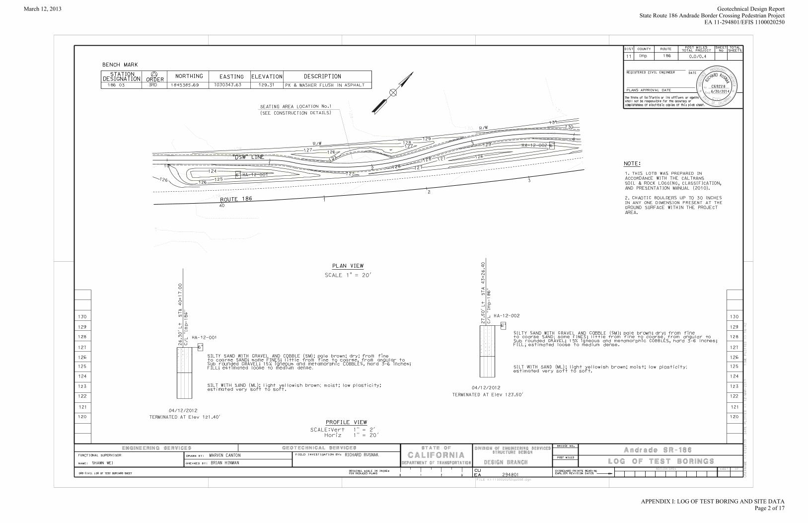
March 12, 2013 Geotechnical Design ReportState Route 186 Andrade Border Crossing Pedestrian Project
EA 11-294801/EFIS 1100020250
APPENDIX I: LOG OF TEST BORING AND SITE DATAPage 2 of 17

March 12, 2013 Geotechnical Design ReportState Route 186 Andrade Border Crossing Pedestrian Project
EA 11-294801/EFIS 1100020250
APPENDIX I: LOG OF TEST BORING AND SITE DATAPage 3 of 17

March 12, 2013 Geotechnical Design ReportState Route 186 Andrade Border Crossing Pedestrian Project
EA 11-294801/EFIS 1100020250
APPENDIX I: LOG OF TEST BORING AND SITE DATAPage 4 of 17

March 12, 2013 Geotechnical Design ReportState Route 186 Andrade Border Crossing Pedestrian Project
EA 11-294801/EFIS 1100020250
APPENDIX I: LOG OF TEST BORING AND SITE DATAPage 5 of 17

March 12, 2013 Geotechnical Design ReportState Route 186 Andrade Border Crossing Pedestrian Project
EA 11-294801/EFIS 1100020250
APPENDIX I: LOG OF TEST BORING AND SITE DATAPage 6 of 17

March 12, 2013 Geotechnical Design ReportState Route 186 Andrade Border Crossing Pedestrian Project
EA 11-294801/EFIS 1100020250
APPENDIX I: LOG OF TEST BORING AND SITE DATAPage 7 of 17

March 12, 2013 Geotechnical Design ReportState Route 186 Andrade Border Crossing Pedestrian Project
EA 11-294801/EFIS 1100020250
APPENDIX I: LOG OF TEST BORING AND SITE DATAPage 8 of 17

March 12, 2013 Geotechnical Design ReportState Route 186 Andrade Border Crossing Pedestrian Project
EA 11-294801/EFIS 1100020250
APPENDIX I: LOG OF TEST BORING AND SITE DATAPage 9 of 17

March 12, 2013 Geotechnical Design ReportState Route 186 Andrade Border Crossing Pedestrian Project
EA 11-294801/EFIS 1100020250
APPENDIX I: LOG OF TEST BORING AND SITE DATAPage 10 of 17

March 12, 2013 Geotechnical Design ReportState Route 186 Andrade Border Crossing Pedestrian Project
EA 11-294801/EFIS 1100020250
APPENDIX I: LOG OF TEST BORING AND SITE DATAPage 11 of 17

March 12, 2013 Geotechnical Design ReportState Route 186 Andrade Border Crossing Pedestrian Project
EA 11-294801/EFIS 1100020250
APPENDIX I: LOG OF TEST BORING AND SITE DATAPage 12 of 17

March 12, 2013 Geotechnical Design ReportState Route 186 Andrade Border Crossing Pedestrian Project
EA 11-294801/EFIS 1100020250
APPENDIX I: LOG OF TEST BORING AND SITE DATAPage 13 of 17

March 12, 2013 Geotechnical Design ReportState Route 186 Andrade Border Crossing Pedestrian Project
EA 11-294801/EFIS 1100020250
APPENDIX I: LOG OF TEST BORING AND SITE DATAPage 14 of 17

March 12, 2013 Geotechnical Design ReportState Route 186 Andrade Border Crossing Pedestrian Project
EA 11-294801/EFIS 1100020250
APPENDIX I: LOG OF TEST BORING AND SITE DATAPage 15 of 17

March 12, 2013 Geotechnical Design ReportState Route 186 Andrade Border Crossing Pedestrian Project
EA 11-294801/EFIS 1100020250
APPENDIX I: LOG OF TEST BORING AND SITE DATAPage 16 of 17

March 12, 2013 Geotechnical Design ReportState Route 186 Andrade Border Crossing Pedestrian Project
EA 11-294801/EFIS 1100020250
APPENDIX I: LOG OF TEST BORING AND SITE DATAPage 17 of 17
March 12, 2013 Geotechnical Design Report State Route 186 Andrade Border Crossing Pedestrian Project EA 11-294801/EFIS 1100020250
APPENDIX II
FIELD EXPLORATION DATA

Not to ScaleDATE 4/24-25/2012
PERCOLATION TESTGEOTECHNICAL DESIGN SOUTH -2
PROJECTSR-186 ANDRADE
BORDER CROSSING SITE LAYOUT E-Fis (ID) 11 0002 0250 N
PARKING LOT
SOAKING PERIOD 24 hrs
TYPE OF SOILSILTY SAND AND GRAVELLY SAND with some CLAY
CONVERSION FACTOR (K) =0.27 + 8.7/DCORRECTION FACTOR © = n [1-(O/D)²] + (I/D)²
TEST MADE BY EGAMBIENT TEMP 60-70 degWEATHER CONDITION CLOUDY
N
PT 1 PT 2 PT 3
PARKING LOT
ANDRADE ROAD
PT-1 PT-368 617 10
0.49
65.75
n = PorosityD = Actual Dia of Test Hole (in)
O = Outside Dia of Perforated Pipe (in)I = Inside Dia of Perforated Pipe (in)
HOLE DIA (in) HOLE DIA (in) 8 HOLE DIA (in)
HOLE NO.HOLE DEPTH (in) HOLE DEPTH (in) 62 HOLE DEPTH (in)HOLE NO. HOLE NO. PT-2
ANDRADE ROAD
CANAL
7 10TIME TIME TIME
1min56sec 6min53sec 9min02sec2min03sec 8min32sec 9min32sec2min06sec 9min12sec 10min02sec2min10sec 9min10sec 10min04sec2min14sec 9min10sec 10min15sec2min18sec 9min13sec 10min08sec
8" - 7" 8" - 7" 8" - 7"8" - 7" 8" - 7" 8" - 7"
8" - 7" 8" - 7" 8" - 7"8" - 7" 8" - 7" 8" - 7"
8" - 7" 8" - 7" 8" - 7"8" - 7" 8" - 7" 8" - 7"
HOLE DIA. (in) HOLE DIA. (in) 8 HOLE DIA. (in)READININGS READININGS READININGS
2.23 Ave of last 3 (min/in)= 10.15
REMARKS: REMARKS: REMARKS:
Ave of last 3 (min/in)= Ave of last 3 (min/in)=R = Average Percolation Rate
9.18R = Average Percolation Rate R = Average Percolation Rate
Time measurements taken for a 1" drop.
Time measurements taken for a 1" drop.
Time measurements taken for a 1" drop.
0.80 0.64
1.51 1.14PERCOLATION RATE CALC. PERCOLATION RATE CALC. PERCOLATION RATE CALC.
4.19 17.26 17.96P = K x R/C P = K x R/C P = K x R/C
CORRECTION FACTOR (C)
CORRECTION FACTOR (C) 0.80
CORRECTION FACTOR (C)
CONVERSION FACTOR (K)
CONVERSION FACTOR (K) 1.51
CONVERSION FACTOR (K)
1 drop. drop. drop.
P = PERCOLATION RATE (min/in) 4.2 P = PERCOLATION
RATE (min/in) 17.3 P = PERCOLATION RATE (min/in) 18.0
March 12, 2013 Geotechnical Design ReportState Route 186 Andrade Border Crossing Pedestrian Project
EA 11-294801/EFIS 1100020250
APPENDIX II: FIELD EXPLORATION DATAPage 1 of 1

March 12, 2013 Geotechnical Design Report State Route 186 Andrade Border Crossing Pedestrian Project EA 11-294801/EFIS 1100020250
APPENDIX III
LABORATORY TEST DATA

Engineered Fill
PARTICLE DIAMETER
% PASSING
STD SIEVE
63.5 10090
100
PARTICLE SIZE DISTRIBUTION
63.5 10050.8 9638.1 9425.4 8219.05 7612.7 669.525 60
40
50
60
70
80
90
100
RC
EN
T P
AS
SIN
G
PARTICLE SIZE DISTRIBUTION
4.76 49 #42.36 43 #81.18 40 #160.6 36 #300.3 25 #50
0.15 16 #100 0
10
20
30
40
50
0.0010.010.1110100
PE
RC
EN
T P
A0.074 12 #2000.005 8 5u0.001 6 1u
Sedimentary Deposits
100
PARTICLE SIZE DISTRIBUTION
00.0010.010.1110100
PARTICLE DIAMETER - mm
PARTICLE DIAMETER
% PASSING
STD SIEVE
4.76 #42.36 #81.18 #160.6 #30
60
70
80
90
100
SIN
G
PARTICLE SIZE DISTRIBUTION
0.3 #500.15 100 #1000.074 83 #2000.005 13 5u0.001 9 1u
20
30
40
50
60
70
PE
RC
EN
T P
AS
SIN
G
0
10
20
30
0.0010.010.1110
P
PARTICLE DIAMETER - mm
March 12, 2013 Geotechnical Design ReportState Route 186 Andrade Border Crossing Pedestrian Project
EA 11-294801/EFIS 1100020250
APPENDIX III: LABORATORY TEST DATAPage 1 of 1
March 12, 2013 Geotechnical Design Report State Route 186 Andrade Border Crossing Pedestrian Project EA 11-294801/EFIS 1100020250
APPENDIX IV
ANALYSES AND CALCULATION

Caltrans ARS Online (v2.0)This web-based tool calculates both deterministic and probabilistic acceleration response spectra for any location in California based on criteria provided in Appendix B of Caltrans Seismic Design Criteria. More...
SELECT SITE LOCATION
Latitude: 32.71869922 Longitude: -114.72812176 VS30: m/s180 Calculate
BASIN LEGEND
Depth to Vs = 1.0 km/s 400 m 500 m 600 m 700 m 800 m 1000 m
Depth to Vs = 2.5 km/s 3.0 km 3.5 km 4.0 km 5.0 km 6.0 km
Eastern Shear Zone
Apply Near Fault Adjustment To: NOTE: Caltrans SDC requires application of a Near Fault Adjustment factor for sites less than 25 km (Rrup) from the causative fault.
Deterministic Spectrum Using
Km Elsinore fault zone (Laguna Salada section)
Km Algodones fault zone
Km San Andreas fault zone south (Coachella section)
81.82
24.52
116.41
Probabilistic Spectrum Using
Km (Recommend Performing Deaggregation To Verify) 24.52
Show Spectrum with Adjustment Only
Show Spectrum with and without near fault Adjustment OK
CALCULATED SPECTRA Display Curves: Printer Friendly View3
Tabular Data Envelope Only Hide Near Fault Axis Scale Show Basin
Map data ©2012 Google, INEGI -
Page 1 of 2ARS Online
8/9/2012http://dap3.dot.ca.gov/shake_stable/v2/
Geotechnical Design ReportState Route 186 Andrade Border Crossing Pedestrian Project
Shade Structures and LuminaireEA 11-294801
EFIS 1100020250
ATTACHMENT 5: ARS ONLINE TOOL RESULTSPage 1 of 3
March 12, 2013 Geotechnical Design ReportState Route 186 Andrade Border Crossing Pedestrian Project
EA 11-294801/EFIS 1100020250
APPENDIX IV: ANALYSES AND CALCULATIONSPage 1 of 3

SITE DATA (ARS Online Version 2.0) Shear Wave Velocity, VS30: 180 m/sLatitude: 32.718699Longitude: -114.728122Depth to Vs = 1.0 km/s: 498 m Depth to Vs = 2.5 km/s: 2.00 km
DETERMINISTIC Elsinore fault zone (Laguna Salada section)
Fault ID: 410Maximum Magnitude (MMax): 7.7Fault Type: SSFault Dip: 90 DegDip Direction: VBottom of Rupture Plane: 13.00 kmTop of Rupture Plane(Ztor): 0.00 kmRrup 81.82 kmRjb: 81.82 kmRx: 77.97 kmFnorm: 0Frev: 0
PeriodSA(BaseSpectrum)
BasinFactor
Near Fault Factor(Applied)
SA(FinalSpectrum)
0.01 0.086 1.000 1.000 0.0860.05 0.097 1.000 1.000 0.0970.1 0.134 1.000 1.000 0.1340.15 0.170 1.000 1.000 0.1700.2 0.194 1.000 1.000 0.1940.25 0.206 1.000 1.000 0.2060.3 0.212 1.000 1.000 0.2120.4 0.203 1.000 1.000 0.2030.5 0.199 1.000 1.000 0.1990.6 0.188 1.002 1.000 0.1880.7 0.179 1.010 1.000 0.1810.85 0.166 1.023 1.000 0.1691 0.153 1.036 1.000 0.1581.2 0.138 1.049 1.000 0.1451.5 0.121 1.060 1.000 0.1282 0.096 1.069 1.000 0.1023 0.063 1.072 1.000 0.0674 0.046 1.069 1.000 0.0495 0.036 1.064 1.000 0.038
Algodones fault zoneFault ID: 442Maximum Magnitude (MMax): 6.6Fault Type: NFault Dip: 50 Deg
Page 1 of 4Printer Friendly View
8/9/2012http://dap3.dot.ca.gov/shake_stable/v2/print_view_tab.php?x=494.70615096476154&y=-57...
Dip Direction: neBottom of Rupture Plane: 15.00 kmTop of Rupture Plane(Ztor): 0.00 kmRrup 24.52 kmRjb: 24.52 kmRx: 0.18 kmFnorm: 1Frev: 0
PeriodSA(BaseSpectrum)
BasinFactor
Near Fault Factor(Applied)
SA(FinalSpectrum)
0.01 0.118 1.000 1.000 0.1180.05 0.139 1.000 1.000 0.1390.1 0.209 1.000 1.000 0.2090.15 0.267 1.000 1.000 0.2670.2 0.291 1.000 1.000 0.2910.25 0.296 1.000 1.000 0.2960.3 0.294 1.000 1.000 0.2940.4 0.273 1.000 1.000 0.2730.5 0.250 1.000 1.000 0.2500.6 0.224 1.001 1.002 0.2250.7 0.203 1.009 1.004 0.2060.85 0.178 1.022 1.007 0.1831 0.157 1.035 1.010 0.1641.2 0.134 1.049 1.010 0.1421.5 0.110 1.062 1.010 0.1182 0.081 1.072 1.010 0.0873 0.049 1.076 1.010 0.0534 0.034 1.074 1.010 0.0375 0.025 1.068 1.010 0.027
San Andreas fault zone south (Coachella section)Fault ID: 396Maximum Magnitude (MMax): 7.9Fault Type: ssFault Dip: 90 DegDip Direction: VBottom of Rupture Plane: 13.10 kmTop of Rupture Plane(Ztor): 0.00 kmRrup 116.41 kmRjb: 116.41 kmRx: 42.20 kmFnorm: 0Frev: 0
PeriodSA(BaseSpectrum)
BasinFactor
Near Fault Factor(Applied)
SA(FinalSpectrum)
0.01 0.072 1.000 1.000 0.072
Page 2 of 4Printer Friendly View
8/9/2012http://dap3.dot.ca.gov/shake_stable/v2/print_view_tab.php?x=494.70615096476154&y=-57...
Geotechnical Design ReportState Route 186 Andrade Border Crossing Pedestrian Project
Shade Structures and LuminaireEA 11-294801
EFIS 1100020250
ATTACHMENT 5: ARS ONLINE TOOL RESULTSPage 2 of 3
March 12, 2013 Geotechnical Design ReportState Route 186 Andrade Border Crossing Pedestrian Project
EA 11-294801/EFIS 1100020250
APPENDIX IV: ANALYSES AND CALCULATIONSPage 2 of 3

0.05 0.079 1.000 1.000 0.0790.1 0.106 1.000 1.000 0.1060.15 0.138 1.000 1.000 0.1380.2 0.161 1.000 1.000 0.1610.25 0.176 1.000 1.000 0.1760.3 0.184 1.000 1.000 0.1840.4 0.180 1.000 1.000 0.1800.5 0.179 1.000 1.000 0.1790.6 0.172 1.002 1.000 0.1730.7 0.167 1.010 1.000 0.1680.85 0.156 1.023 1.000 0.1591 0.146 1.036 1.000 0.1511.2 0.133 1.049 1.000 0.1401.5 0.118 1.060 1.000 0.1252 0.095 1.068 1.000 0.1013 0.063 1.071 1.000 0.0684 0.046 1.069 1.000 0.0505 0.037 1.063 1.000 0.039
PROBABILISTIC
Probabilistic Model USGS Seismic Hazard Map(2008) 975 Year Return Period
PeriodSA(Base Spectrum)
BasinFactor
Near FaultFactor(Applied)
SA(FinalSpectrum)
0.01 0.338 1.000 1.000 0.3380.05 0.475 1.000 1.000 0.4750.1 0.550 1.000 1.000 0.5500.15 0.648 1.000 1.000 0.6480.2 0.727 1.000 1.000 0.7270.25 0.739 1.000 1.000 0.7390.3 0.749 1.000 1.000 0.7490.4 0.707 1.000 1.000 0.7070.5 0.677 1.000 1.000 0.6770.6 0.616 1.004 1.002 0.6200.7 0.568 1.008 1.004 0.5750.85 0.501 1.017 1.007 0.5131 0.445 1.028 1.010 0.4611.2 0.381 1.038 1.010 0.4001.5 0.316 1.052 1.010 0.3352 0.248 1.069 1.010 0.2683 0.147 1.078 1.010 0.1604 0.105 1.081 1.010 0.1145 0.085 1.082 1.010 0.093
Page 3 of 4Printer Friendly View
8/9/2012http://dap3.dot.ca.gov/shake_stable/v2/print_view_tab.php?x=494.70615096476154&y=-57...
Envelope Data Period SA0.01 0.3380.05 0.4750.1 0.5500.15 0.6480.2 0.7270.25 0.7390.3 0.7490.4 0.7070.5 0.6770.6 0.6200.7 0.5750.85 0.5131 0.4611.2 0.4001.5 0.3352 0.2683 0.1604 0.1145 0.093
Page 4 of 4Printer Friendly View
8/9/2012http://dap3.dot.ca.gov/shake_stable/v2/print_view_tab.php?x=494.70615096476154&y=-57...
Geotechnical Design ReportState Route 186 Andrade Border Crossing Pedestrian Project
Shade Structures and LuminaireEA 11-294801
EFIS 1100020250
ATTACHMENT 5: ARS ONLINE TOOL RESULTSPage 3 of 3
March 12, 2013 Geotechnical Design ReportState Route 186 Andrade Border Crossing Pedestrian Project
EA 11-294801/EFIS 1100020250
APPENDIX IV: ANALYSES AND CALCULATIONSPage 3 of 3