information for the machine tool builder · 2014-12-03 · information for the machine tool builder...
TRANSCRIPT
iTNC 530 HSCIThe Versatile Contouring Controlfor Milling, Drilling, BoringMachines and MachiningCenters
Information for the Machine
Tool Builder
September 2013

2
TNC contouring control with drive system from HEIDENHAIN
General information
iTNC 530 Contouring control for milling, drilling and boring machines,
and machining centers
Up to 18 axes and closed-loop main spindleHEIDENHAIN inverter systems and motors recommendedUniformly digital with HSCI interface and EnDat interfaceTFT color flat-panel display, 19-inch or 15-inchStorage medium: HDR hard disk with 160 GB / SSDR solid statedisk with 32 GBProgramming in HEIDENHAIN conversational format, withsmarT.NC or according to DIN/ISOStandard milling, drilling and boring cyclesTouch probe cyclesFK free contour programmingSpecial functions for fast 3-D machiningShort block processing time (0.5 ms)Automatic calculation of cutting dataPallet management
System test Controls, motors and encoders from HEIDENHAIN are in mostcases integrated as components in larger systems. In thesecases, comprehensive tests of the complete system are required,irrespective of the specifications of the individual devices.
Expendable parts In particular the following parts in controls from HEIDENHAIN aresubject to wear:
Hard diskBuffer batteryFan
Standards Standards (ISO, EN, etc.) apply only where explicitly stated in thecatalog.
Note Microsoft Windows, Windows 2000, Windows XP, WindowsVista, Windows 7 and the Internet Explorer are registeredtrademarks of Microsoft Corporation.
Validity The features and specifications described here apply for thefollowing control and NC software versions:
iTNC 530 HSCI with NC software versions
606420-04 (export license required) 606421-04 (no export license required)
This catalog supersedes all previous editions, which therebybecome invalid. Subject to change without notice.
Prerequisites Some of these specifications require particular machineconfigurations. Please note also that, for some functions, a specialPLC program must be created by the manufacturer.
Functional safety If no explicit distinction is made between standard and FScomponents (FS = functional safety), then the data and otherinformation apply to both versions (e.g. TE 745, TE 745 FS).
3
Contents
TNC contouring control with drive system from HEIDENHAIN 2
Overview tables 4
HSCI control components 15
Accessories 32
Cable overview 45
Technical description 52
Data transfer and communication 79
Mounting information 82
Overall dimensions 84
General information 107
Other HEIDENHAIN controls 109
Subject index 110
Please refer to the page references in the tables with thespecifications.
4
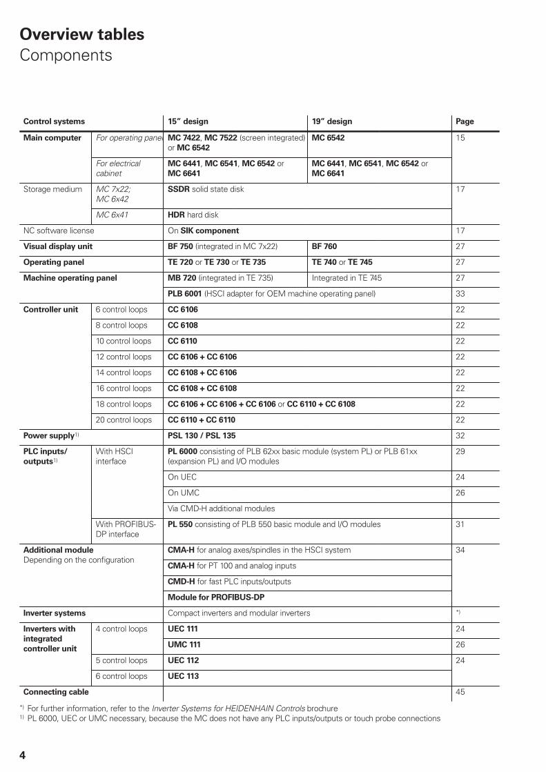
Overview tables
Components
Control systems 15” design 19” design Page
For operating panel MC 7422, MC 7522 (screen integrated)or MC 6542
MC 6542Main computer
For electricalcabinet
MC 6441, MC 6541, MC 6542 orMC 6641
MC 6441, MC 6541, MC 6542 orMC 6641
15
MC 7x22;MC 6x42
SSDR solid state diskStorage medium
MC 6x41 HDR hard disk
17
NC software license On SIK component 17
Visual display unit BF 750 (integrated in MC 7x22) BF 760 27
Operating panel TE 720 or TE 730 or TE 735 TE 740 or TE 745 27
MB 720 (integrated in TE 735) Integrated in TE 745 27Machine operating panel
PLB 6001 (HSCI adapter for OEM machine operating panel) 33
6 control loops CC 6106 22
8 control loops CC 6108 22
10 control loops CC 6110 22
12 control loops CC 6106 + CC 6106 22
14 control loops CC 6108 + CC 6106 22
16 control loops CC 6108 + CC 6108 22
18 control loops CC 6106 + CC 6106 + CC 6106 or CC 6110 + CC 6108 22
Controller unit
20 control loops CC 6110 + CC 6110 22
Power supply1) PSL 130 / PSL 135 32
PL 6000 consisting of PLB 62xx basic module (system PL) or PLB 61xx(expansion PL) and I/O modules
29
On UEC 24
On UMC 26
With HSCIinterface
Via CMD-H additional modules
PLC inputs/
outputs1)
With PROFIBUS-DP interface
PL 550 consisting of PLB 550 basic module and I/O modules 31
CMA-H for analog axes/spindles in the HSCI system
CMA-H for PT 100 and analog inputs
CMD-H for fast PLC inputs/outputs
Additional module
Depending on the configuration
Module for PROFIBUS-DP
34
Inverter systems Compact inverters and modular inverters *)
UEC 111 244 control loops
UMC 111 26
5 control loops UEC 112
Inverters with
integrated
controller unit
6 control loops UEC 113
24
Connecting cable 45
*) For further information, refer to the Inverter Systems for HEIDENHAIN Controls brochure1) PL 6000, UEC or UMC necessary, because the MC does not have any PLC inputs/outputs or touch probe connections

5
Accessories
Accessories iTNC 530 Page
Electronic handwheels • HR 410 portable handwheel or• HR 520 portable handwheel with display or• HR 550 FS portable wireless handwheel with display or• HR 130 panel-mounted handwheel or• Up to three HR 150 panel-mounted handwheels via HRA 110 handwheel adapter
38
Workpiece touch probes TS 230 touch trigger probe with cable connection orTS 440 touch trigger probe with infrared transmission orTS 444 touch trigger probe with infrared transmission orTS 640 touch trigger probe with infrared transmission orTS 740 touch trigger probe with infrared transmission
36
Tool touch probes TT 140 touch trigger probe with cable connection orTT 449 touch trigger probe with infrared transmission orTL Nano laser system for contact-free workpiece measurement orTL Micro laser system for contact-free workpiece measurement
37
USB hub 80
Programming station Control software for PCs for programming, archiving, and trainingSingle-station license with original control keyboardSingle-station license with virtual keyboardNetwork license with virtual keyboardDemo version with virtual keyboard or PC keyboard—free of charge
*)
Industrial PC IPC 6110/IPC 6120—Remote operation of the control and data transferIPC 6641—Industrial PC for Windows
41
Snap-on keys For the controlFor the handwheel
4342
*) For more information, refer to the Programming Station TNC brochure.
Accessories / Software iTNC 530 Page
PLCdesign1) PLC development software 76
KinematicsDesign1) Software for creating kinematics and initializing DCM 66
TNCremo2) Data transfer software 80
TNCremoPlus2) Data transfer software with “live” screen 80
CycleDesign1) Software for creating cycle structures 78
Software Key Generator1) Software for enabling SIK options for a limited time 17
TNCscope1) Software for data recording 73
DriveDiag1) Software for diagnosis of digital control loops 72
TNCopt1) Software for putting digital control loops into service 72
IOconfig1) Software for configuring PLC I/O and PROFIBUS-DP components 30
TeleService1) Software for remote diagnostics, monitoring, and operation 73
RemoTools SDK1) Function library for developing customized applications for communication withHEIDENHAIN controls
81
virtualTNC1) Control component for virtual machines 81
1) Available to registered customers for downloading from the Internet2) Available to all customers (without registration) for downloading from the Internet
6
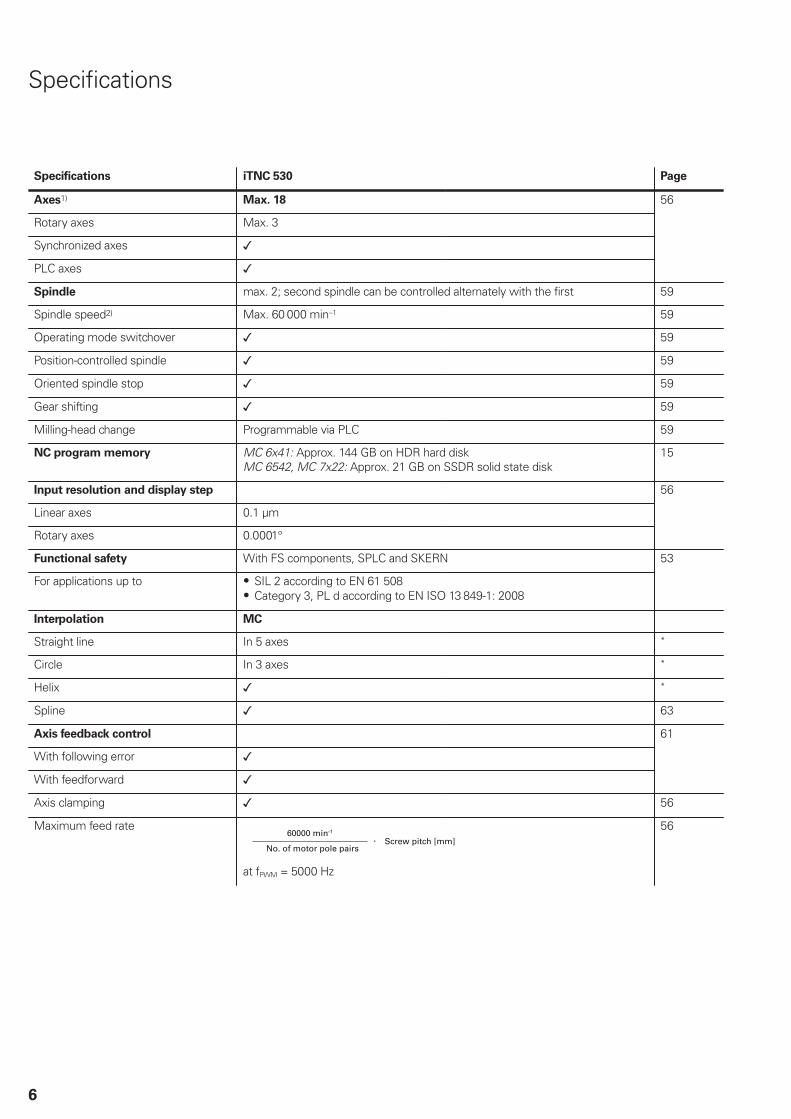
Specifications
Specifications iTNC 530 Page
Axes1) Max. 18
Rotary axes Max. 3
Synchronized axes
PLC axes
56
Spindle max. 2; second spindle can be controlled alternately with the first 59
Spindle speed2) Max. 60 000 min–1 59
Operating mode switchover 59
Position-controlled spindle 59
Oriented spindle stop 59
Gear shifting 59
Milling-head change Programmable via PLC 59
NC program memory MC 6x41: Approx. 144 GB on HDR hard disk MC 6542, MC 7x22: Approx. 21 GB on SSDR solid state disk
15
Input resolution and display step
Linear axes 0.1 μm
Rotary axes 0.0001°
56
Functional safety With FS components, SPLC and SKERN
For applications up to SIL 2 according to EN 61 508Category 3, PL d according to EN ISO 13 849-1: 2008
53
Interpolation MC
Straight line In 5 axes *
Circle In 3 axes *
Helix *
Spline 63
Axis feedback control
With following error
With feedforward
61
Axis clamping 56
Maximum feed rate60000 min–1
Screw pitch [mm]No. of motor pole pairs
at fPWM = 5000 Hz
56

7
Specifications iTNC 530 Page
Cycle times of main computer MC 62
Block processing 0.5 ms 63
Cycle times of controller unit CC/UEC/UMC 62
Path interpolation 3 ms
Fine interpolation Single speed: 0.2 ms Double speed: 0.1 ms (option 49)
Position controller Single speed: 0.2 ms Double speed: 0.1 ms (option 49)
Speed controller Single speed: 0.2 ms Double speed: 0.1 ms (option 49)
Current controller fPWM 3333 Hz4000 Hz5000 Hz 6666 Hz8000 Hz 10 000 Hz
TINT
150 μs 125 μs 100 μs75 μs with option 4960 μs with option 4950 μs with option 49
62
Permissible temperature range Operation: In electrical cabinet: 5 °C to 40 °CIn operating panel: 0 °C to 50 °CStorage: –20 °C to 60 °C
*) For further information, refer to the iTNC 530 brochure (ID 892921-xx)1) As ordered2) On motors with two pole pairs
8
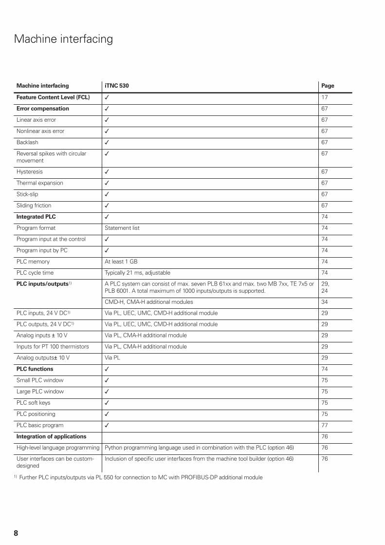
Machine interfacing
Machine interfacing iTNC 530 Page
Feature Content Level (FCL) 17
Error compensation 67
Linear axis error 67
Nonlinear axis error 67
Backlash 67
Reversal spikes with circularmovement
67
Hysteresis 67
Thermal expansion 67
Stick-slip 67
Sliding friction 67
Integrated PLC 74
Program format Statement list 74
Program input at the control 74
Program input by PC 74
PLC memory At least 1 GB 74
PLC cycle time Typically 21 ms, adjustable 74
A PLC system can consist of max. seven PLB 61xx and max. two MB 7xx, TE 7x5 orPLB 6001. A total maximum of 1000 inputs/outputs is supported.
29,24
PLC inputs/outputs1)
CMD-H, CMA-H additional modules 34
PLC inputs, 24 V DC1) Via PL, UEC, UMC, CMD-H additional module 29
PLC outputs, 24 V DC1) Via PL, UEC, UMC, CMD-H additional module 29
Analog inputs 10 V Via PL, CMA-H additional module 29
Inputs for PT 100 thermistors Via PL, CMA-H additional module 29
Analog outputs 10 V Via PL 29
PLC functions 74
Small PLC window 75
Large PLC window 75
PLC soft keys 75
PLC positioning 75
PLC basic program 77
Integration of applications 76
High-level language programming Python programming language used in combination with the PLC (option 46) 76
User interfaces can be custom-designed
Inclusion of specific user interfaces from the machine tool builder (option 46) 76
1) Further PLC inputs/outputs via PL 550 for connection to MC with PROFIBUS-DP additional module
9
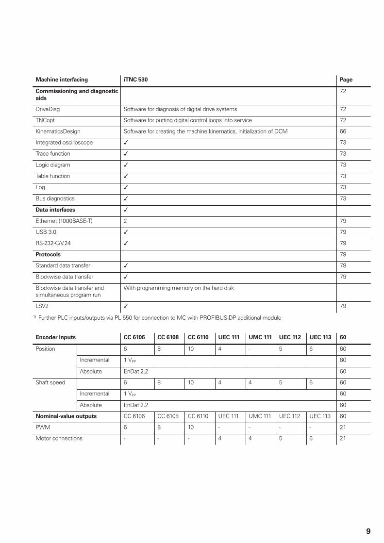
Machine interfacing iTNC 530 Page
Commissioning and diagnostic
aids
72
DriveDiag Software for diagnosis of digital drive systems 72
TNCopt Software for putting digital control loops into service 72
KinematicsDesign Software for creating the machine kinematics, initialization of DCM 66
Integrated oscilloscope 73
Trace function 73
Logic diagram 73
Table function 73
Log 73
Bus diagnostics 73
Data interfaces
Ethernet (1000BASE-T) 2 79
USB 3.0 79
RS-232-C/V.24 79
Protocols 79
Standard data transfer 79
Blockwise data transfer 79
Blockwise data transfer andsimultaneous program run
With programming memory on the hard disk
LSV2 79
1) Further PLC inputs/outputs via PL 550 for connection to MC with PROFIBUS-DP additional module
Encoder inputs CC 6106 CC 6108 CC 6110 UEC 111 UMC 111 UEC 112 UEC 113 60
6 8 10 4 - 5 6 60
Incremental 1 VPP 60
Position
Absolute EnDat 2.2 60
6 8 10 4 4 5 6 60
Incremental 1 VPP 60
Shaft speed
Absolute EnDat 2.2 60
Nominal-value outputs CC 6106 CC 6108 CC 6110 UEC 111 UMC 111 UEC 112 UEC 113 60
PWM 6 8 10 - - - - 21
Motor connections - - - 4 4 5 6 21
10
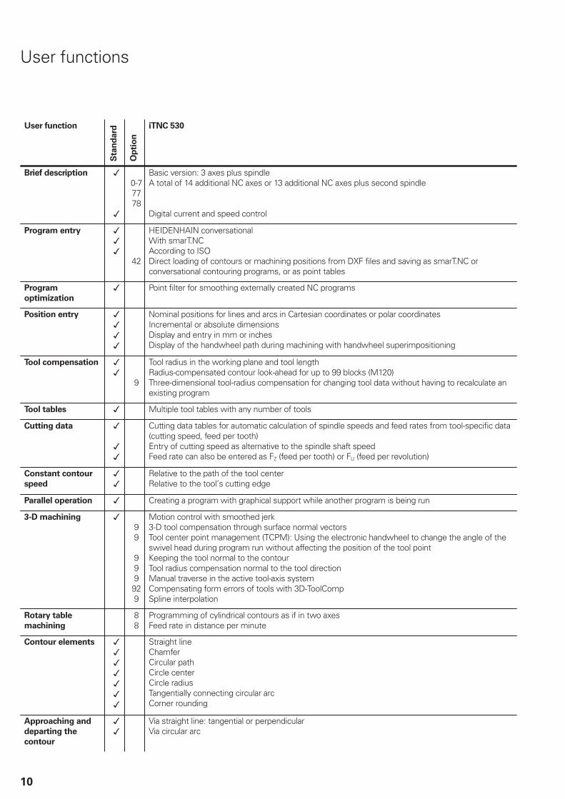
User functions
User function
Sta
nd
ard
Op
tio
niTNC 530
Brief description
0-77778
Basic version: 3 axes plus spindle A total of 14 additional NC axes or 13 additional NC axes plus second spindle
Digital current and speed control
Program entry
42
HEIDENHAIN conversationalWith smarT.NCAccording to ISODirect loading of contours or machining positions from DXF files and saving as smarT.NC orconversational contouring programs, or as point tables
Program
optimization
Point filter for smoothing externally created NC programs
Position entry Nominal positions for lines and arcs in Cartesian coordinates or polar coordinatesIncremental or absolute dimensionsDisplay and entry in mm or inchesDisplay of the handwheel path during machining with handwheel superimpositioning
Tool compensation
9
Tool radius in the working plane and tool lengthRadius-compensated contour look-ahead for up to 99 blocks (M120)Three-dimensional tool-radius compensation for changing tool data without having to recalculate anexisting program
Tool tables Multiple tool tables with any number of tools
Cutting data Cutting data tables for automatic calculation of spindle speeds and feed rates from tool-specific data(cutting speed, feed per tooth)Entry of cutting speed as alternative to the spindle shaft speedFeed rate can also be entered as FZ (feed per tooth) or FU (feed per revolution)
Constant contour
speed
Relative to the path of the tool centerRelative to the tool’s cutting edge
Parallel operation Creating a program with graphical support while another program is being run
3-D machining
99
999929
Motion control with smoothed jerk3-D tool compensation through surface normal vectorsTool center point management (TCPM): Using the electronic handwheel to change the angle of theswivel head during program run without affecting the position of the tool pointKeeping the tool normal to the contourTool radius compensation normal to the tool directionManual traverse in the active tool-axis systemCompensating form errors of tools with 3D-ToolCompSpline interpolation
Rotary table
machining
88
Programming of cylindrical contours as if in two axesFeed rate in distance per minute
Contour elements Straight lineChamferCircular pathCircle centerCircle radiusTangentially connecting circular arcCorner rounding
Approaching and
departing the
contour
Via straight line: tangential or perpendicularVia circular arc
11
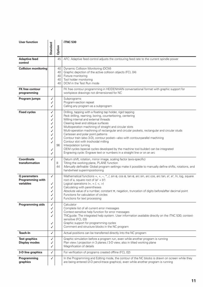
User function
Sta
nd
ard
Op
tio
n
iTNC 530
Adaptive feed
control
45 AFC: Adaptive feed control adjusts the contouring feed rate to the current spindle power
Collision monitoring 4040404040
Dynamic Collision Monitoring (DCM)Graphic depiction of the active collision objects (FCL 04)Fixture monitoringTool holder monitoringDCM in the Test Run mode
FK free contour
programming
FK free contour programming in HEIDENHAIN conversational format with graphic support forworkpiece drawings not dimensioned for NC
Program jumps SubprogramsProgram-section repeatCalling any program as a subprogram
Fixed cycles
96
Drilling, tapping with a floating tap holder, rigid tappingPeck drilling, reaming, boring, counterboring, centeringMilling internal and external threadsClearing level and oblique surfacesMultioperation machining of straight and circular slotsMulti-operation machining of rectangular and circular pockets, rectangular and circular studsCartesian and polar point patternsContour train (also 3-D), contour pocket—also with contour-parallel machiningContour slot with trochoidal millingInterpolation turningOEM cycles (special cycles developed by the machine tool builder) can be integratedEngraving cycle: Engrave text or numbers in a straight line or on an arc
Coordinate
transformation 844
Datum shift, rotation, mirror image, scaling factor (axis-specific)Tilting the working plane, PLANE functionManually definable: Global program settings make it possible to manually define shifts, rotations, andhandwheel superimpositioning
Q parameters
Programming with
variables
Mathematical functions =, +, –, *, /, sin , cos , tan , arc sin, arc cos, arc tan, an, en, In, log, squareroot of a, square root of (a2 + b2)Logical operations (=, = /, <, >)Calculating with parenthesesAbsolute value of a number, constant , negation, truncation of digits before/after decimal pointFunctions for calculation of circlesFunctions for text processing
Programming aids CalculatorComplete list of all current error messagesContext-sensitive help function for error messagesTNCguide: The integrated help system. User information available directly on the iTNC 530; context-sensitive (FCL 03)Graphic support for programming cyclesComment and structure blocks in the NC program
Teach-In Actual positions can be transferred directly into the NC program
Test graphics
Display modes
Graphic simulation before a program run, even while another program is runningPlan view / projection in 3 planes / 3-D view, also in tilted working planeMagnification of details
3-D line graphics For verification of programs created offline (FCL 02)
Programming
graphics
In the Programming and Editing mode, the contour of the NC blocks is drawn on screen while theyare being entered (2-D pencil-trace graphics), even while another program is running

12
User functionS
tan
dard
Op
tio
n
iTNC 530
Program-run
graphics
Display modes
Graphic simulation during real-time machiningPlan view / projection in 3 planes / 3-D view
Machining time Calculation of machining time in the Test Run operating modeDisplay of the current machining time in the Program Run operating modes
Returning to the
contour
Mid-program startup in any block in the program, returning the tool to the calculated nominal positionto continue machining; the graphic support in smarT.NC also lets you return to a point patternProgram interruption, contour departure and return
Datum
management
One table per traverse range for storing reference points
Datum tables Several datum tables for storing workpiece-related datums
Pallet tables Pallet tables (with as many entries as desired for the selection of pallets, NC programs and datums)can be machined workpiece by workpiece
Touch probe cycles
48
Touch probe calibrationCompensation of workpiece misalignment, manual or automaticDatum setting, manual or automaticAutomatic tool and workpiece measurementGlobal setting of touch-probe parameters (FCL 02)Probing cycle for three-dimensional measurements. Toggle between showing the measurementresults in the coordinate system of the workpiece or the machine (FCL 03)Automatic measurement and optimization of machine kinematics
Conversational
languages
41
English, German, Chinese (traditional, simplified), Czech, Danish, Dutch, Finnish, French, Hungarian,Italian, Polish, Portuguese, Russian (Cyrillic), Spanish, SwedishFor more conversational languages, see Options, Page 13

13
Options
Option
number
Option As of NC
software
60642x-
ID Comment
0 Additional axis 01 ID 354540-01 Additional control loop 1
1 Additional axis 01 ID 353904-01 Additional control loop 2
2 Additional axis 01 ID 353905-01 Additional control loop 3
3 Additional axis 01 ID 367867-01 Additional control loop 4
4 Additional axis 01 ID 367868-01 Additional control loop 5
5 Additional axis 01 ID 370291-01 Additional control loop 6
6 Additional axis 01 ID 370292-01 Additional control loop 7
7 Additional axis 01 ID 370293-01 Additional control loop 8
8 Software option 1 01 ID 367591-01 Rotary table machining
Programming of cylindrical contours as if in two axesFeed rate in distance per minute
Coordinate transformation
Tilting the working plane, PLANE function
Interpolation
Circular in 3 axes with tilted working plane
9 Software option 2 01 ID 367590-01 3-D machining
3-D tool compensation through surface normal vectorsTool center point management (TCPM): Using the electronichandwheel to change the angle of the swivel head duringprogram run without affecting the position of the tool pointKeeping the tool normal to the contourTool radius compensation normal to the tool directionManual traverse in the active tool-axis system
Interpolation
Linear in 5 axes (export license required)Spline: execution of splines (3rd degree polynomial)
18 HEIDENHAIN DNC 01 ID 526451-01 Communication with external PC applications over COMcomponent
40 DCM collision 01 ID 526452-01 Dynamic Collision Monitoring (DCM)
41 Additional language01 ID 530184-01
ID 530184-02ID 530184-04ID 530184-06ID 530184-08ID 530184-09
Additional conversational language: SlovenianSlovakNorwegianKoreanTurkishRomanian
42 DXF converter 01 ID 526450-01 Load and convert DXF contours
44 Global PGMsettings
01 ID 576057-01 Global program settings
45 Adaptive feedcontrol (AFC)
01 ID 579648-01 Adaptive feed control
46 Python OEMprocess
01 ID 579650-01 Python application on the iTNC
48 KinematicsOpt 01 ID 630916-01 Touch probe cycles for automatic measurement of rotary axes
49 Double-speed axis 01 ID 632223-01 Short control-loop cycle times for direct drives
14
Option
number
Option As of NC
software
60642x-
ID Comment
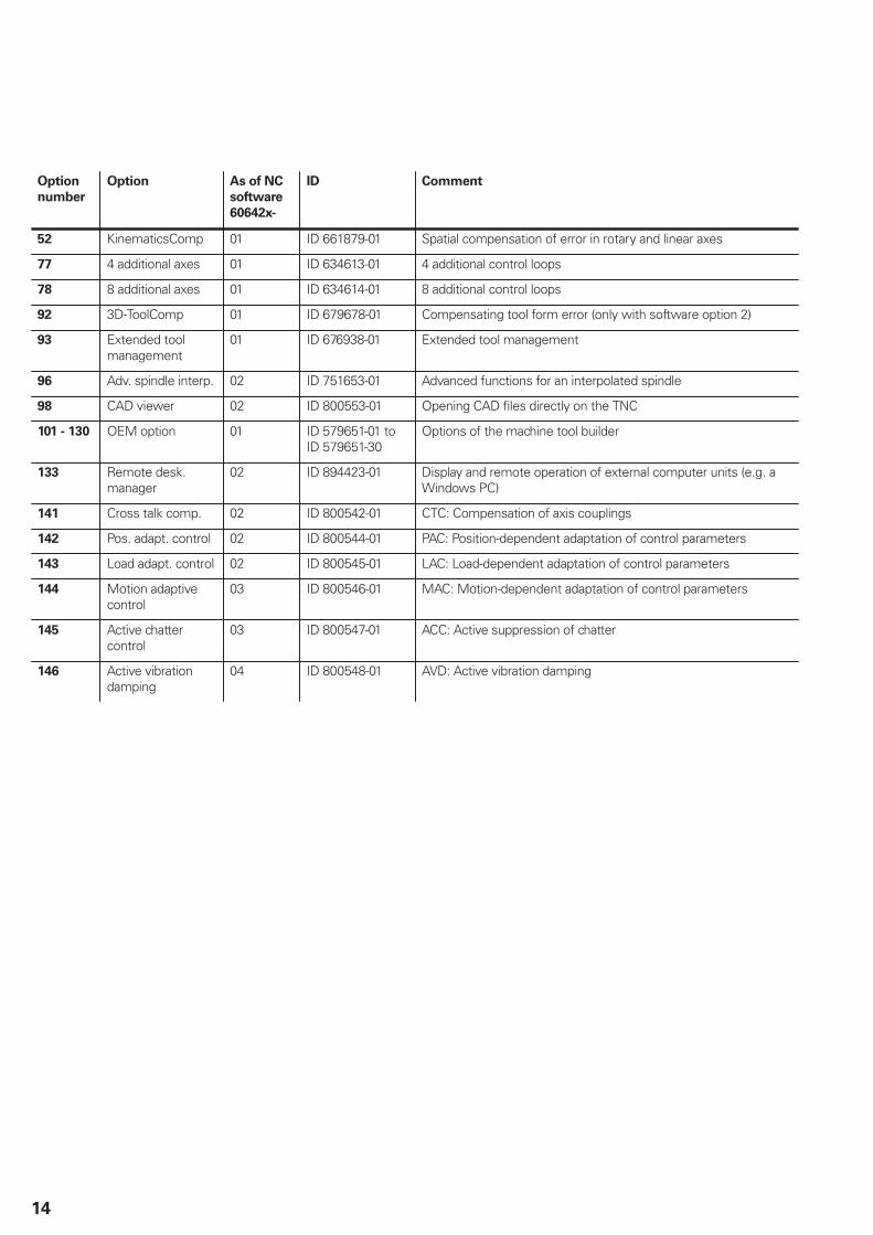
52 KinematicsComp 01 ID 661879-01 Spatial compensation of error in rotary and linear axes
77 4 additional axes 01 ID 634613-01 4 additional control loops
78 8 additional axes 01 ID 634614-01 8 additional control loops
92 3D-ToolComp 01 ID 679678-01 Compensating tool form error (only with software option 2)
93 Extended toolmanagement
01 ID 676938-01 Extended tool management
96 Adv. spindle interp. 02 ID 751653-01 Advanced functions for an interpolated spindle
98 CAD viewer 02 ID 800553-01 Opening CAD files directly on the TNC
101 - 130 OEM option 01 ID 579651-01 to ID 579651-30
Options of the machine tool builder
133 Remote desk.manager
02 ID 894423-01 Display and remote operation of external computer units (e.g. aWindows PC)
141 Cross talk comp. 02 ID 800542-01 CTC: Compensation of axis couplings
142 Pos. adapt. control 02 ID 800544-01 PAC: Position-dependent adaptation of control parameters
143 Load adapt. control 02 ID 800545-01 LAC: Load-dependent adaptation of control parameters
144 Motion adaptivecontrol
03 ID 800546-01 MAC: Motion-dependent adaptation of control parameters
145 Active chattercontrol
03 ID 800547-01 ACC: Active suppression of chatter
146 Active vibrationdamping
04 ID 800548-01 AVD: Active vibration damping

15
HSCI control components
Main computer
Main computer The MC main computers feature:ProcessorRAM memoryHSCI interface to the CC 6xxx or UEC/UMC and to other controlcomponentsHDL interface to the BF 7xx visual display unit (BF integrated inMC 7x22)USB 3.0 interface to the TE 7xx operating panel
To be ordered separately, and installed in the main computer bythe OEM:
HDR or SSDR storage medium with the NC softwareSIK component (System Identification Key) for enabling thecontrol loops and software options
The following HSCI components are necessary for operation ofthe iTNC 530:
MC main computerController unitPLB 62xx PLC input/output unit (system PL; integrated in UEC/UMC)MB 720 machine operating panel (integrated in TE 7x5) orPLB 6001 HSCI adapter for connection of an OEM machineoperating panel
Interfaces The standard MC main computers feature USB 3.0, RS-232-C/V.24and Ethernet interfaces for use by the end user. Connection toPROFIBUS-DP is possible via an additional module.
Power supply 24 V DC of power are supplied to the main computer and otherHSCI components by the PSL 13x supply unit. For the entireHSCI system, the 24 V DC NC supply voltage for the controlcomponents is required to be safely separated voltage (PELV).It must not be connected to the 24 V DC supply voltage for PLCcomponents (e.g. holding brakes).
Export version Because the entire NC software is saved on the memory card(HDR or SSDR), no export version is required for the maincomputer itself. Export versions are available only for the easilyreplaceable storage medium and the SIK component.

16
Versions Various versions of the MC main computer are available:For installation in the operating panel
The MC 7x22 and the BF visual display unit (15“) form one unit,and are installed directly in the operating panel. Advantage: except for the power supply line, only one HSCIconnecting cable to the electrical cabinet is necessary.For installation in the electrical cabinet
The MC 6x41 is installed in the electrical cabinet. HSCI, USBand HDL cables to the operating panel are required as controllines.For installation in the operating panel or electrical cabinet
Because the SSDR solid state disk is used as a storagemedium, the MC 6542 can be universally integrated. HSCI, USBand HDL cables to the operating panel are required as controllines.
The main computers listed are supported as of NC software60642x-04. These MC main computers cannot be run on earliersoftware versions.
MC 6x41
MC 6542
MC 7x22 with main computer installed on the back
To be
installed in
Storage
medium
Processor RAM
memory
Power
loss
Weight
MC 7422 Operatingpanel
SSDR Intel Celeron 10471.4 GHz 2 cores
2 GB 52 W 7.5 kg ID 1039537-01
MC 7522 Operatingpanel
SSDR Intel Core i7-31.7 GHz 2 cores
2 GB 60 W 7.5 kg ID 1071597-01
MC 6542 Operatingpanel orelectricalcabinet
SSDR Intel Core i7-31.7 GHz 2 cores
2 GB 48 W 4.0 kg ID 1081188-01
MC 6441 Electricalcabinet
HDR Intel Celeron 10471.4 GHz 2 cores
2 GB 40 W 4.0 kg ID 1054739-01
MC 6541 Electricalcabinet
HDR Intel Core i7-31.7 GHz 2 cores
2 GB 48 W 4.0 kg ID 1081185-01
MC 6641 Electricalcabinet
HDR Intel Core i7-32.1 GHz 4 cores
2 GB 75 W 4.0 kg ID 811550-01

17
Options The capabilities of the iTNC 530 can also be adapted retroactivelywith options to meet new requirements. These options aredescribed on page 13. They are enabled by entering keywordsbased on the SIK number, and are saved in the SIK component.Please indicate your SIK number when ordering new options.
Storage medium The storage medium is removable and must be ordered separatelyfrom the main computer. It contains the NC software 60642x-04.Depending on the main computer, the HDR hard disk or the SSDRsolid state disk is used as a storage medium. The NC software isbased on the HEIDENHAIN HEROS 5 operating system.
HDR hard disk
Free capacity 144 GBFor main computer MC 6441, MC 6541,
MC 6641Export license required ID 682272-04No export license required ID 682272-54
SSDR solid state disk
Free capacity 21 GBFor main computer MC 6542, MC 7422,
MC 7522Export license required ID 736591-04No export license required ID 736591-54
HDR hard disk
SSDR solid state disk
SIK component The SIK component contains the NC software license forenabling control loops and software options. It gives the maincomputer an unambiguous ID code—the SIK number. The SIKcomponent is ordered and shipped separately. It must be insertedin a special slot in the MC main computer.
The SIK component with the NC software license is available invarious versions, depending on the enabled control loops andoptions. Further control loops – up to the maximum numberavailable (see Controller Unit) – can be enabled later by entering akeyword. HEIDENHAIN provides the keyword, which is based onthe SIK number.
When ordering, please indicate the SIK number of your control.When the keywords are entered in the control, they are savedin the SIK component. This enables and activates the options.Should service become necessary, the SIK component must beinserted in the replacement control to enable all required options.
SIK component
Master keyword(general key)
There is a master keyword (general key) for putting the iTNC 530into service that will unlock all options for a duration of 90 days.After this period, only those options with the correct keywords willbe active. The general key is activated via a soft key.

18
Software Key Gen-erator (accessory)
The PC software makes it possible to generate an activation codefor software options on HEIDENHAIN controls. The selectedoption is enabled for a limited time (10 to 90 days). It can onlybe enabled once. You generate the desired activation code byentering the SIK number, the option to be enabled, the durationand a manufacturer-specific password. Option enabling isindependent of the general key.
Feature ContentLevel (FCL)
On the iTNC 530, error fixes and software improvements wereseparated from each other as of NC software 34049x-02. Error
fixes are usually free of charge and contained in updates of theNC software. In contrast, software improvements are availablefor a fee. They are offered as “feature upgrades” and are enabledvia the Feature Content Level (FCL) option (ID 529969-01). Thefeatures in a feature content level are listed in User functions. Forthe current NC software 60642x-xx, there are not yet any FCLsoftware improvements that are subject to a fee.

19
NC software
license and
enabling of
control loops
depending on the
CC
Recommended combinations NC software license
Without
software
option
Incl. option 8 Incl. options 8
and 9A
cti
ve
co
ntr
ol lo
op
s
CC
6106
CC
6108
CC
611
0
2 x
CC
6106
CC
6106
+
CC
6108
2 x
CC
6108
SIK SIK SIK
Included
options
4 ID 586084-20 ID 586084-70
ID 586084-09 ID 586084-59
ID 586084-01 ID 586084-51
-
5 ID 586084-24 ID 586084-74
ID 586084-17 ID 586084-67
ID 586084-02 ID 586084-52
0
6 ID 586084-25 ID 586084-75
ID 586084-18 ID 586084-68
ID 586084-03 ID 586084-53
0, 1
7 ID 586084-26 ID 586084-76
ID 586084-19 ID 586084-69
ID 586084-04 ID 586084-54
0, 1, 2
8 ID 586084-27 ID 586084-77
ID 586084-23 ID 586084-73
ID 586084-05 ID 586084-55
77
9 ID 586084-06 ID 586084-56
77, 0
10 ID 586084-07 ID 586084-57
77, 0, 1
11 ID 586084-10 ID 586084-60
77, 0 ,1 ,2
12 ID 586084-11 ID 586084-61
78
13 ID 586084-12 ID 586084-62
78, 0
14 ID 586084-13 ID 586084-63
78, 0, 1
15 ID 586084-14 ID 586084-64
78, 0, 1, 2
16
Only through subsequent enablingof control loops (additional axes)
ID 586084-15 ID 586084-65
77, 78
17 -
20
Only through subsequent enabling of control loops(additional axes)
77, 78,0...3
(Italics: Export version)
20
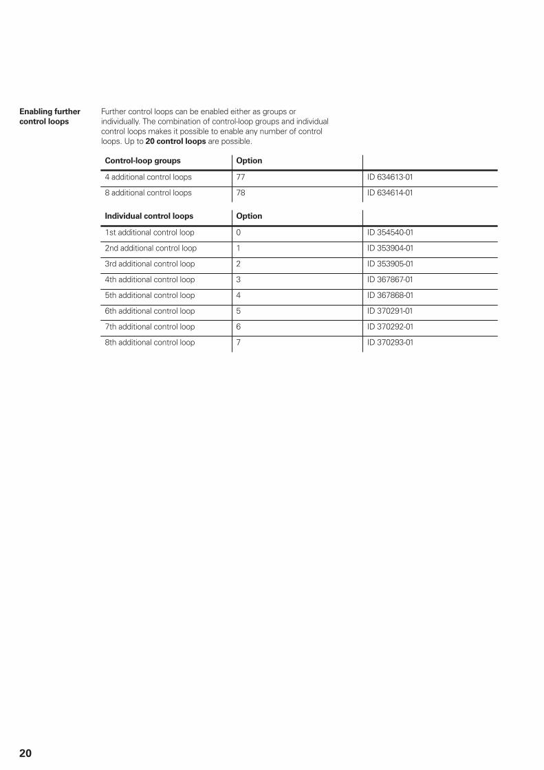
Enabling further
control loops
Further control loops can be enabled either as groups orindividually. The combination of control-loop groups and individualcontrol loops makes it possible to enable any number of controlloops. Up to 20 control loops are possible.
Control-loop groups Option
4 additional control loops 77 ID 634613-01
8 additional control loops 78 ID 634614-01
Individual control loops Option
1st additional control loop 0 ID 354540-01
2nd additional control loop 1 ID 353904-01
3rd additional control loop 2 ID 353905-01
4th additional control loop 3 ID 367867-01
5th additional control loop 4 ID 367868-01
6th additional control loop 5 ID 370291-01
7th additional control loop 6 ID 370292-01
8th additional control loop 7 ID 370293-01

21
Controller unit
Controller unit Due to the very short cycle times of the position, speed andcurrent controllers, the controller units from HEIDENHAIN areequally suited for conventional drives, for direct drives (linearmotors, torque motors) and for HSC spindles. They permit a highloop gain and short reaction times to changing machining forces,and so make the high contour accuracy and surface quality of theworkpiece possible.
Single speedDouble speed
Single-speed control loops are usually sufficient for linear ortorque motors and for conventional axes. Double-speed control
loops (option 49) are preferred for HSC spindles and axes that aredifficult to control. In the default setting, all axes are set to singlespeed. Each axis that is switched from single speed to doublespeed can reduce the number of available control loops by one.PWM frequencies greater than 5 kHz require double-speed controlloops, for which option 49 must be enabled.
Cycle times Speed controllerWith fPWM Current controller
Single-speed Double-speed
Position controller
3333 Hz 150 μs 300 μs 150 μs
4000 Hz 125 μs 250 μs 125 μs
5000 Hz 100 μs 200 μs 100 μs
6666 Hz1) 75 μs 150 μs 150 μs
8000 Hz1) 60 μs 125 μs 125 μs
10000 Hz1) 50 μs 100 μs 100 μs
Same as speed
controller
1) Possible only with option 49
Number of controlloops
The number of enabled control loops depends on the SIK (seeMain computer), or on additionally enabled control loops, whichcan also be ordered as needed later.
Versions Modular CC 61xx controller units with PWM interface to theinvertersCompact UEC/UMC inverters with integrated controller unit
Controller units, main computers and inverters operate in anydesired combination.
22
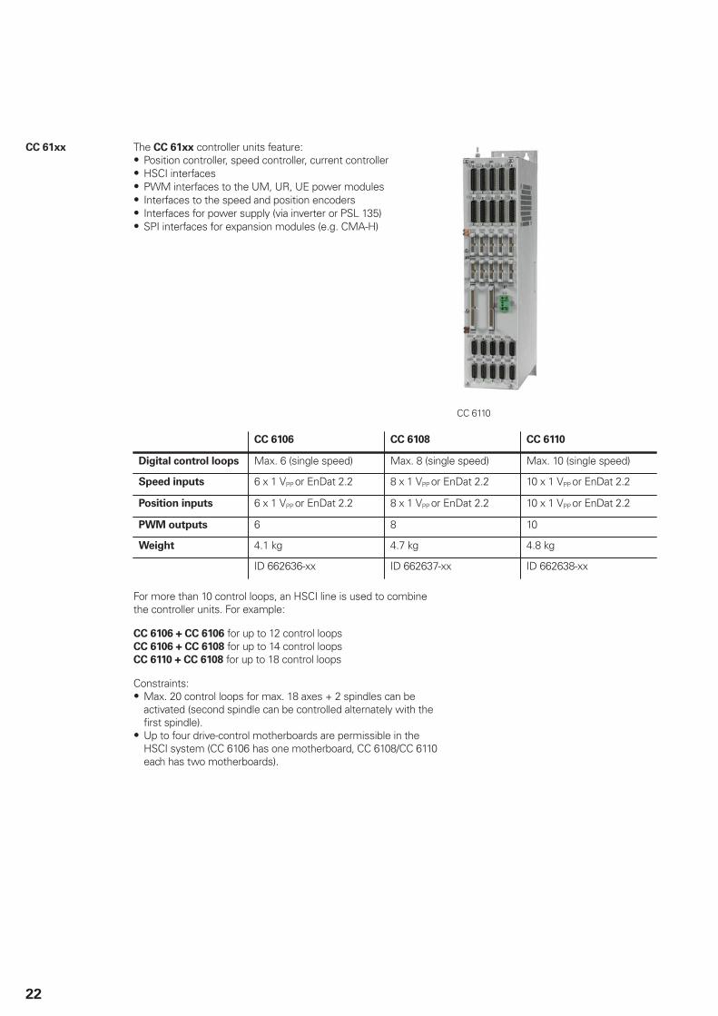
CC 61xx The CC 61xx controller units feature:Position controller, speed controller, current controllerHSCI interfacesPWM interfaces to the UM, UR, UE power modulesInterfaces to the speed and position encodersInterfaces for power supply (via inverter or PSL 135)SPI interfaces for expansion modules (e.g. CMA-H)
CC 6110
CC 6106 CC 6108 CC 6110
Digital control loops Max. 6 (single speed) Max. 8 (single speed) Max. 10 (single speed)
Speed inputs 6 x 1 VPP or EnDat 2.2 8 x 1 VPP or EnDat 2.2 10 x 1 VPP or EnDat 2.2
Position inputs 6 x 1 VPP or EnDat 2.2 8 x 1 VPP or EnDat 2.2 10 x 1 VPP or EnDat 2.2
PWM outputs 6 8 10
Weight 4.1 kg 4.7 kg 4.8 kg
ID 662636-xx ID 662637-xx ID 662638-xx
For more than 10 control loops, an HSCI line is used to combinethe controller units. For example:
CC 6106 + CC 6106 for up to 12 control loops CC 6106 + CC 6108 for up to 14 control loops CC 6110 + CC 6108 for up to 18 control loops
Constraints:Max. 20 control loops for max. 18 axes + 2 spindles can beactivated (second spindle can be controlled alternately with thefirst spindle).Up to four drive-control motherboards are permissible in theHSCI system (CC 6106 has one motherboard, CC 6108/CC 6110each has two motherboards).
23
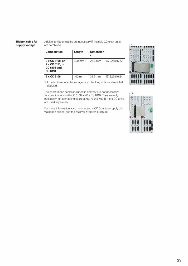
Ribbon cable for
supply voltage
Additional ribbon cables are necessary if multiple CC 6xxx unitsare combined.
Combination Length Dimension
c
2 x CC 6108, or
2 x CC 6110, or
CC 6108 and
CC 6110
300 mm1) 26.5 mm ID 325816-22
2 x CC 6106 100 mm 31.5 mm ID 325816-24
1) In order to reduce the voltage drop, the long ribbon cable is leddoubled.
The short ribbon cables included in delivery are not necessaryfor combinations with CC 6108 and/or CC 6110. They are onlynecessary for connecting sockets X69 A and X69 B if the CC unitsare used separately.
For more information about connecting a CC 6xxx to a supply unitvia ribbon cables, see the Inverter Systems brochure.
24
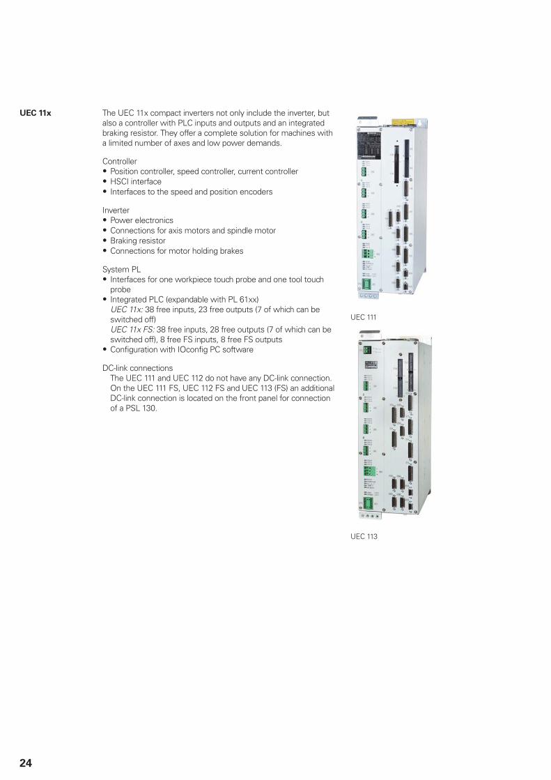
UEC 11x The UEC 11x compact inverters not only include the inverter, butalso a controller with PLC inputs and outputs and an integratedbraking resistor. They offer a complete solution for machines witha limited number of axes and low power demands.
ControllerPosition controller, speed controller, current controllerHSCI interfaceInterfaces to the speed and position encoders
InverterPower electronicsConnections for axis motors and spindle motorBraking resistorConnections for motor holding brakes
System PLInterfaces for one workpiece touch probe and one tool touchprobeIntegrated PLC (expandable with PL 61xx)UEC 11x: 38 free inputs, 23 free outputs (7 of which can beswitched off)UEC 11x FS: 38 free inputs, 28 free outputs (7 of which can beswitched off), 8 free FS inputs, 8 free FS outputsConfiguration with IOconfig PC software
DC-link connectionsThe UEC 111 and UEC 112 do not have any DC-link connection.On the UEC 111 FS, UEC 112 FS and UEC 113 (FS) an additionalDC-link connection is located on the front panel for connectionof a PSL 130.
UEC 111
UEC 113

25
UEC 111/UEC 112/UEC 113
Controller 4/5/6 digital control loops
Speed inputs 4/5/6 x 1 VPP or EnDat 2.2
Position inputs 4/5/6 x 1 VPP or EnDat 2.2
Inverter 2/3/4 axes 1 axis Spindle
3333 Hz 6.0/12.0 A 9.0/18.0 A 24.0/36.0 A
4000 Hz 5.5/11.0 A 8.3/16.5 A 22.0/33.0 A
5000 Hz 5.0/10.0 A 7.5/15.0 A 20.0/30.0 A
6666 Hz 4.2/8.4 A 6.3/12.6 A 16.8/25.2 A
8000 Hz 3.6/7.3 A 5.5/11.0 A 14.6/21.9 A
Rated current IN/
maximum current Imax1)
at a PWM frequency of
10000 Hz 3.0/6.0 A 4.6/9.2 A 12.2/18.3 A
Supply voltage2) 3 x 400 V AC (± 10 %); 50 Hz
Rated power of DC link 14 kW
Peak power3) of DC link 18 kW / 25 kW
Power loss at IN 450 W
DC-link voltage 565 V DC
Integral braking resistance4) 2.1 kW / 27 kW
Power pack for HSCI components 24 V DC / 3.5 A
Module width 150 mm
Weight 20 kg
Functional safety -
UEC 111
UEC 112
UEC 113
ID 625777-xx ID 625779-xx ID 828471-xx
ID 1075825-xxID 1075826-xx ID 1038694-xx
1) Axes: 0.2 s cyclic duration factor for duty cycle time of 10 s with 70 % rated current preload Spindle: 10 s cyclic duration factor for duty cycle time of 60 s with 70 % rated current preload
2) For UL certification: 3 x 480 V AC (+6%/-10%); 60 Hz3) 1st value: 40 % cyclic duration factor for 10 minutes duty cycle time (S6-40 %)
2nd value: 4 s cyclic duration factor for 20 seconds duty cycle time.4) 1st value: Continuous duty
2nd value: Peak power (1.5 % cyclic duration factor for 120 seconds duty cycle time).
26
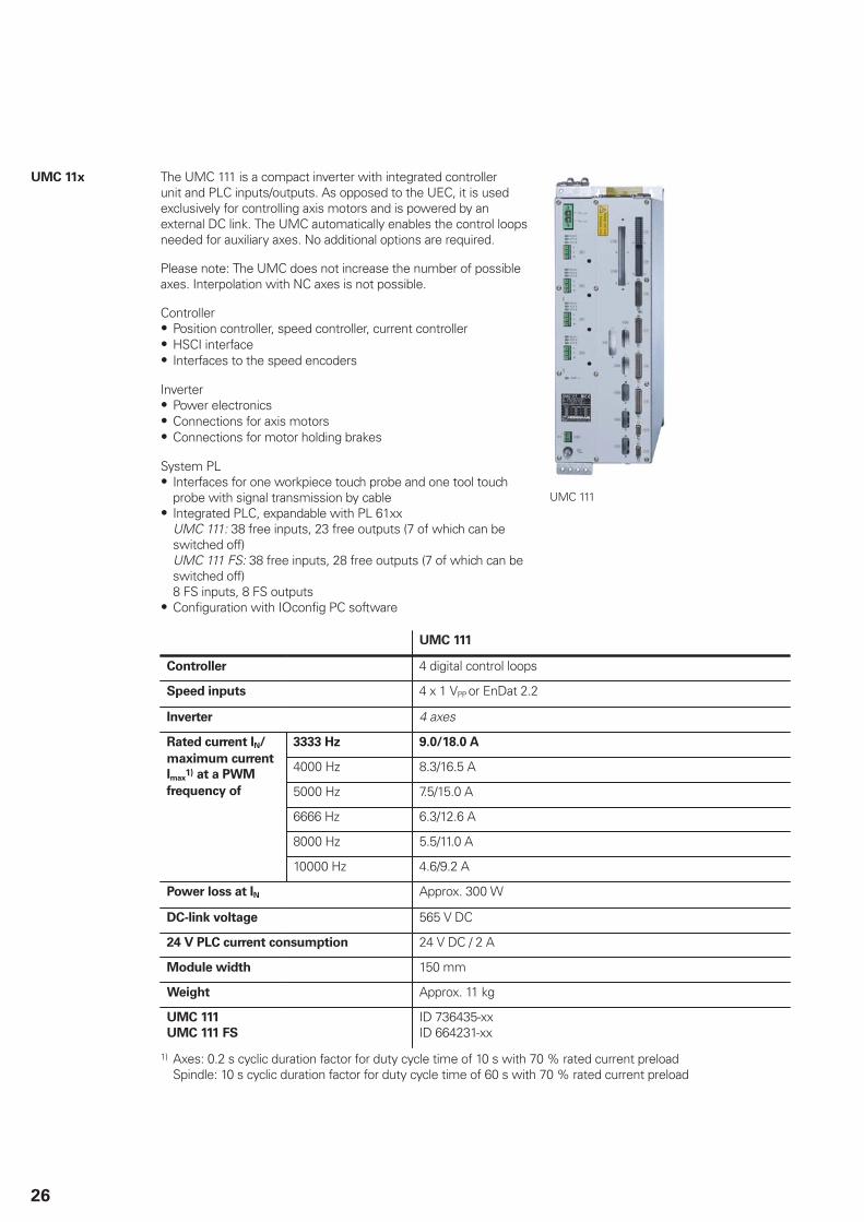
UMC 11x The UMC 111 is a compact inverter with integrated controllerunit and PLC inputs/outputs. As opposed to the UEC, it is usedexclusively for controlling axis motors and is powered by anexternal DC link. The UMC automatically enables the control loopsneeded for auxiliary axes. No additional options are required.
Please note: The UMC does not increase the number of possibleaxes. Interpolation with NC axes is not possible.
ControllerPosition controller, speed controller, current controllerHSCI interfaceInterfaces to the speed encoders
InverterPower electronicsConnections for axis motorsConnections for motor holding brakes
System PLInterfaces for one workpiece touch probe and one tool touchprobe with signal transmission by cableIntegrated PLC, expandable with PL 61xxUMC 111: 38 free inputs, 23 free outputs (7 of which can beswitched off)UMC 111 FS: 38 free inputs, 28 free outputs (7 of which can beswitched off)8 FS inputs, 8 FS outputsConfiguration with IOconfig PC software
UMC 111
UMC 111
Controller 4 digital control loops
Speed inputs 4 x 1 VPP or EnDat 2.2
Inverter 4 axes
3333 Hz 9.0/18.0 A
4000 Hz 8.3/16.5 A
5000 Hz 7.5/15.0 A
6666 Hz 6.3/12.6 A
8000 Hz 5.5/11.0 A
Rated current IN/
maximum current
Imax1) at a PWM
frequency of
10000 Hz 4.6/9.2 A
Power loss at IN Approx. 300 W
DC-link voltage 565 V DC
24 V PLC current consumption 24 V DC / 2 A
Module width 150 mm
Weight Approx. 11 kg
UMC 111
UMC 111 FS
ID 736435-xxID 664231-xx
1) Axes: 0.2 s cyclic duration factor for duty cycle time of 10 s with 70 % rated current preload Spindle: 10 s cyclic duration factor for duty cycle time of 60 s with 70 % rated current preload

27
15" screen and keyboard
BF 750 color flat-
panel display
Power supply: 24 V DC / approx. 50 W15.1-inch; 1024 x 768 pixelsHDL interface to the MC 6xxx8 horizontal soft keys, 6 vertical soft keys for PLCSoft-key row switchoverScreen layoutOperating mode switchoverUSB port with cover cap on frontIntegrated USB hub with four USB interfaces on the rear
BF 750 ID 785080-01Weight Approx. 4 kg BF 750
TE 730 keyboard For BF 750, MC 7422 or MC 7522Axis keysThe keys for axes IV and V are exchangeable snap-on keys.Contouring keysOperating mode keysASCII keyboardSpindle-speed and feed-rate override potentiometersUSB interface to the MCTouchpad
TE 730 ID 805489-01Weight Approx. 4.2 kg
TE 730
TE 720 keyboard Same features as TE 730 but without touchpad
TE 720 ID 805488-01
TE 735 keyboard
unit with
integrated
machine
operating panel
For BF 750, MC 7422 or MC 7522NC keyboard same as TE 730USB interface to the MC main computerMachine operating panel (same as MB 720)HSCI interface
TE 735 ID 771898-01TE 735 FS ID 805493-01Weight Approx. 3.4 kg
TE 735
MB 720 machine
operating panel
Power supply 24 V DC / approx. 4 WSuitable for BF 75036 exchangeable snap-on keys with status LEDs, freelydefinable via PLCOperating elements: 12 axis keys, 24 function keys, NC start1),NC stop1), spindle start, spindle stop (all snap-on keys),emergency stop button, control voltage on1); 2 holes foradditional keys or keylock switchesHSCI interfaceMB 720: 7 free PLC inputs and 5 free PLC outputs MB 720 FS: 4 free FS inputs and 5 free PLC outputs; and dual-channel FS inputs for emergency stop and permissive buttons ofthe handwheel.
1) Keys illuminated, addressable via PLC
MB 720 ID 784803-01MB 720 FS ID 805474-01Weight Approx. 1 kg
MB 720
28
19" screen and keyboard
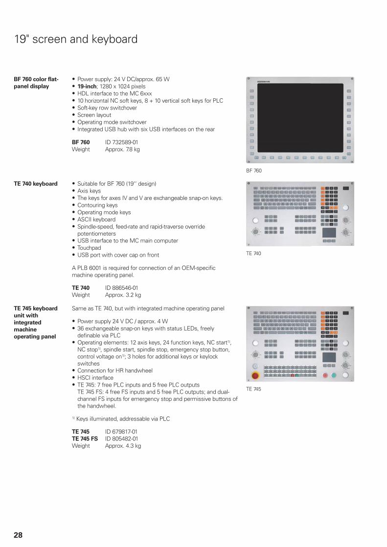
BF 760 color flat-
panel display
Power supply: 24 V DC/approx. 65 W19-inch; 1280 x 1024 pixelsHDL interface to the MC 6xxx10 horizontal NC soft keys, 8 + 10 vertical soft keys for PLCSoft-key row switchoverScreen layoutOperating mode switchoverIntegrated USB hub with six USB interfaces on the rear
BF 760 ID 732589-01Weight Approx. 7.8 kg
BF 760
TE 740 keyboard Suitable for BF 760 (19‘‘ design)Axis keysThe keys for axes IV and V are exchangeable snap-on keys.Contouring keysOperating mode keysASCII keyboardSpindle-speed, feed-rate and rapid-traverse overridepotentiometersUSB interface to the MC main computerTouchpadUSB port with cover cap on front
A PLB 6001 is required for connection of an OEM-specificmachine operating panel.
TE 740 ID 886546-01Weight Approx. 3.2 kg
TE 740
TE 745 keyboard
unit with
integrated
machine
operating panel
Same as TE 740, but with integrated machine operating panel
Power supply 24 V DC / approx. 4 W36 exchangeable snap-on keys with status LEDs, freelydefinable via PLCOperating elements: 12 axis keys, 24 function keys, NC start1),NC stop1), spindle start, spindle stop, emergency stop button,control voltage on1); 3 holes for additional keys or keylockswitchesConnection for HR handwheelHSCI interfaceTE 745: 7 free PLC inputs and 5 free PLC outputs TE 745 FS: 4 free FS inputs and 5 free PLC outputs; and dual-channel FS inputs for emergency stop and permissive buttons ofthe handwheel.
1) Keys illuminated, addressable via PLC
TE 745 ID 679817-01TE 745 FS ID 805482-01Weight Approx. 4.3 kg
TE 745
29
PL 6000 PLC input/output systems with HSCI
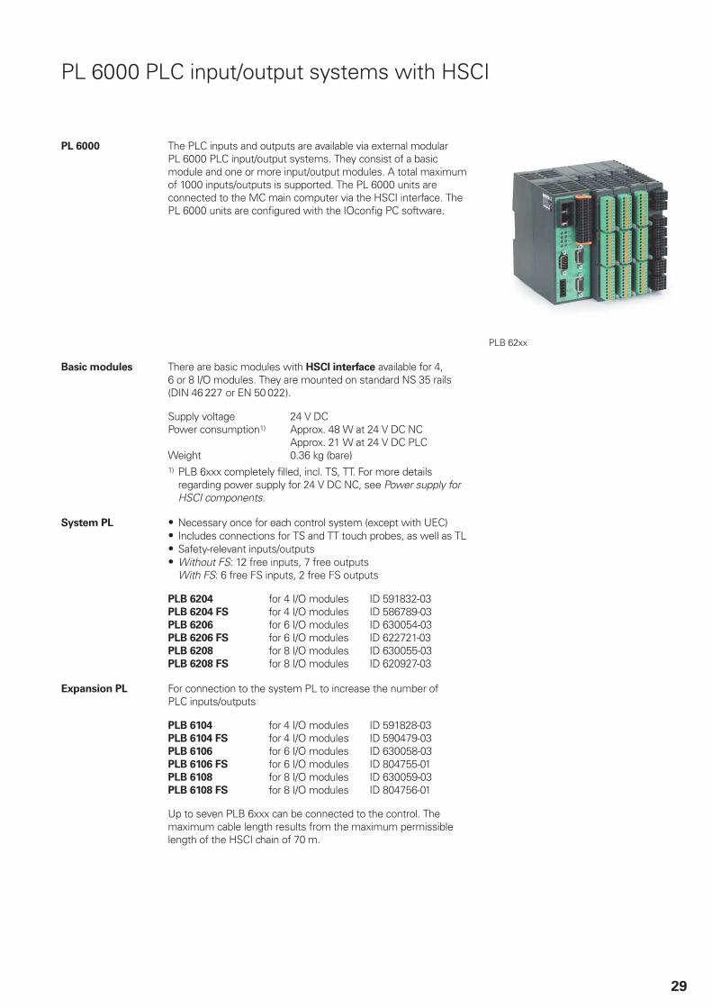
PL 6000 The PLC inputs and outputs are available via external modularPL 6000 PLC input/output systems. They consist of a basicmodule and one or more input/output modules. A total maximumof 1000 inputs/outputs is supported. The PL 6000 units areconnected to the MC main computer via the HSCI interface. ThePL 6000 units are configured with the IOconfig PC software.
PLB 62xx
Basic modules There are basic modules with HSCI interface available for 4,6 or 8 I/O modules. They are mounted on standard NS 35 rails(DIN 46 227 or EN 50 022).
Supply voltage 24 V DCPower consumption1) Approx. 48 W at 24 V DC NC
Approx. 21 W at 24 V DC PLCWeight 0.36 kg (bare)1) PLB 6xxx completely filled, incl. TS, TT. For more details
regarding power supply for 24 V DC NC, see Power supply forHSCI components.
System PL Necessary once for each control system (except with UEC)Includes connections for TS and TT touch probes, as well as TLSafety-relevant inputs/outputsWithout FS: 12 free inputs, 7 free outputsWith FS: 6 free FS inputs, 2 free FS outputs
PLB 6204 for 4 I/O modules ID 591832-03PLB 6204 FS for 4 I/O modules ID 586789-03PLB 6206 for 6 I/O modules ID 630054-03PLB 6206 FS for 6 I/O modules ID 622721-03PLB 6208 for 8 I/O modules ID 630055-03PLB 6208 FS for 8 I/O modules ID 620927-03
Expansion PL For connection to the system PL to increase the number ofPLC inputs/outputs
PLB 6104 for 4 I/O modules ID 591828-03PLB 6104 FS for 4 I/O modules ID 590479-03PLB 6106 for 6 I/O modules ID 630058-03PLB 6106 FS for 6 I/O modules ID 804755-01PLB 6108 for 8 I/O modules ID 630059-03PLB 6108 FS for 8 I/O modules ID 804756-01
Up to seven PLB 6xxx can be connected to the control. Themaximum cable length results from the maximum permissiblelength of the HSCI chain of 70 m.

30
I/O modules for
HSCI
There are I/O modules with digital and analog inputs and outputs.For partially occupied basic modules, the unused slots must beoccupied by an empty housing.
PLD-H 16-08-00 I/O module with 16 digital inputs and 8 digital outputs
ID 594243-02
PLD-H 08-16-00 I/O module with 8 digital inputs and 16 digital outputs
ID 650891-02
PLD-H 08-04-00 FS I/O module with 8 digital FS inputs and 4 digital FS outputs
ID 598905-02
PLD-H 04-08-00 FS I/O module with 4 digital FS inputs and 8 digital FS outputs
ID 727219-02
Total current Outputs 1 to 7: 2 A per output ( 8 A simultaneously)Power output Max. 200 WWeight 0.2 kg
PLA-H 08-04-04 Analog module for PL 6xxx with8 analog inputs, ± 10 V4 analog outputs, ± 10 V4 analog inputs for PT 100 thermistors
ID 675572-01
Weight 0.2 kg
Empty housing For unused slots ID 383022-11
IOconfig
(accessory)
PC software for configuring HSCI and PROFIBUS components
31
PL 550 PLC input/output system for PROFIBUS-DP
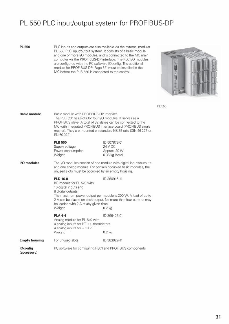
PL 550 PLC inputs and outputs are also available via the external modularPL 550 PLC input/output system. It consists of a basic moduleand one or more I/O modules, and is connected to the MC maincomputer via the PROFIBUS-DP interface. The PLC I/O modulesare configured with the PC software IOconfig. The additionalmodule for PROFIBUS-DP (Page 35) must be installed in theMC before the PLB 550 is connected to the control.
PL 550
Basic module Basic module with PROFIBUS-DP interfaceThe PLB 550 has slots for four I/O modules. It serves as aPROFIBUS slave. A total of 32 slaves can be connected to theMC with integrated PROFIBUS interface board (PROFIBUS singlemaster). They are mounted on standard NS 35 rails (DIN 46 227 orEN 50 022).
PLB 550 ID 507872-01Supply voltage 24 V DCPower consumption Approx. 20 WWeight 0.36 kg (bare)
I/O modules The I/O modules consist of one module with digital inputs/outputsand one analog module. For partially occupied basic modules, theunused slots must be occupied by an empty housing.
PLD 16-8 ID 360916-11I/O module for PL 5x0 with16 digital inputs and 8 digital outputs. The maximum power output per module is 200 W. A load of up to2 A can be placed on each output. No more than four outputs maybe loaded with 2 A at any given time.Weight 0.2 kg
PLA 4-4 ID 366423-01Analog module for PL 5x0 with4 analog inputs for PT 100 thermistors4 analog inputs for ± 10 VWeight 0.2 kg
Empty housing For unused slots ID 383022-11
IOconfig
(accessory)
PC software for configuring HSCI and PROFIBUS components
32
Accessories
Power supply for HSCI components
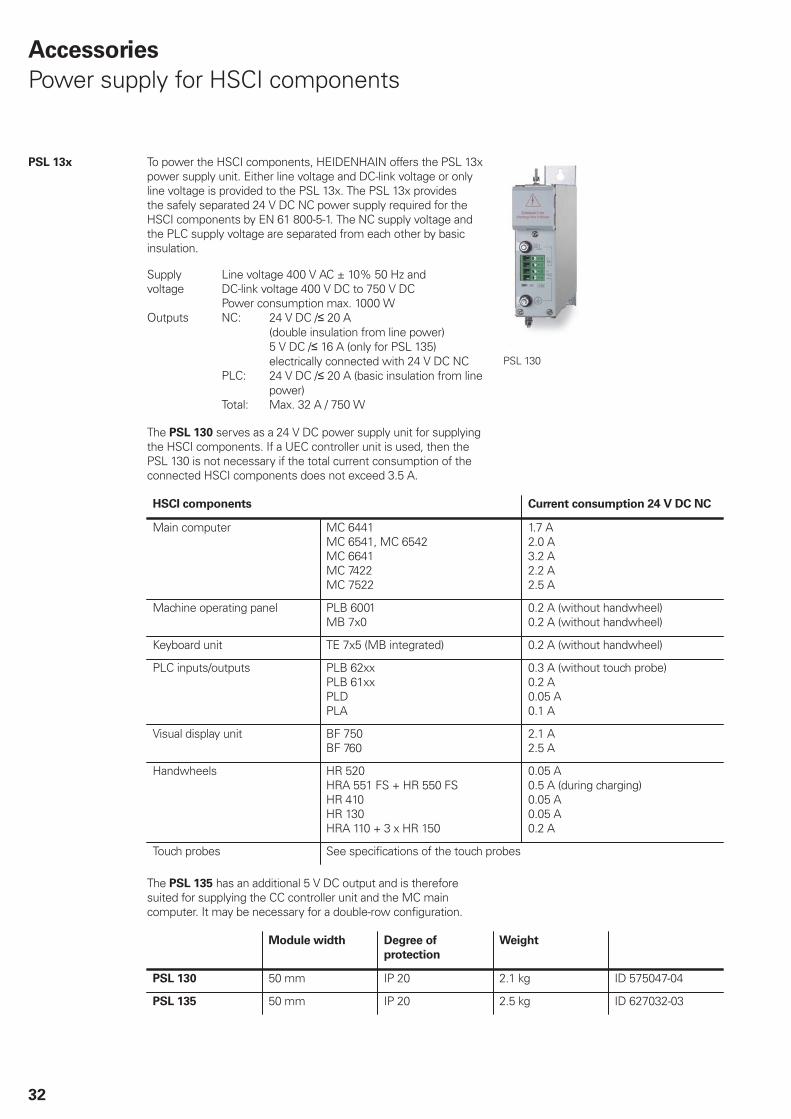
PSL 13x To power the HSCI components, HEIDENHAIN offers the PSL 13xpower supply unit. Either line voltage and DC-link voltage or onlyline voltage is provided to the PSL 13x. The PSL 13x providesthe safely separated 24 V DC NC power supply required for theHSCI components by EN 61 800-5-1. The NC supply voltage andthe PLC supply voltage are separated from each other by basicinsulation.
Supplyvoltage
Line voltage 400 V AC ± 10% 50 Hz andDC-link voltage 400 V DC to 750 V DCPower consumption max. 1000 W
Outputs NC: 24 V DC / 20 A (double insulation from line power) 5 V DC / 16 A (only for PSL 135) electrically connected with 24 V DC NC
PLC: 24 V DC / 20 A (basic insulation from linepower)
Total: Max. 32 A / 750 W
PSL 130
The PSL 130 serves as a 24 V DC power supply unit for supplyingthe HSCI components. If a UEC controller unit is used, then thePSL 130 is not necessary if the total current consumption of theconnected HSCI components does not exceed 3.5 A.
HSCI components Current consumption 24 V DC NC
Main computer MC 6441MC 6541, MC 6542 MC 6641 MC 7422MC 7522
1.7 A2.0 A 3.2 A2.2 A2.5 A
Machine operating panel PLB 6001MB 7x0
0.2 A (without handwheel)0.2 A (without handwheel)
Keyboard unit TE 7x5 (MB integrated) 0.2 A (without handwheel)
PLC inputs/outputs PLB 62xx PLB 61xx PLD PLA
0.3 A (without touch probe) 0.2 A 0.05 A 0.1 A
Visual display unit BF 750 BF 760
2.1 A 2.5 A
Handwheels HR 520 HRA 551 FS + HR 550 FS HR 410 HR 130 HRA 110 + 3 x HR 150
0.05 A 0.5 A (during charging) 0.05 A 0.05 A 0.2 A
Touch probes See specifications of the touch probes
The PSL 135 has an additional 5 V DC output and is thereforesuited for supplying the CC controller unit and the MC maincomputer. It may be necessary for a double-row configuration.
Module width Degree of
protection
Weight
PSL 130 50 mm IP 20 2.1 kg ID 575047-04
PSL 135 50 mm IP 20 2.5 kg ID 627032-03
33
HSCI adapter for OEM machine operating panel
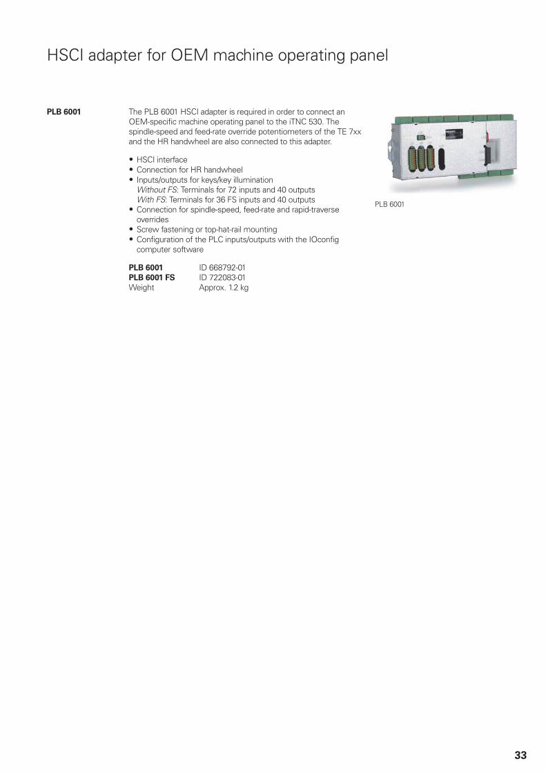
PLB 6001 The PLB 6001 HSCI adapter is required in order to connect anOEM-specific machine operating panel to the iTNC 530. Thespindle-speed and feed-rate override potentiometers of the TE 7xxand the HR handwheel are also connected to this adapter.
HSCI interfaceConnection for HR handwheelInputs/outputs for keys/key illumination Without FS: Terminals for 72 inputs and 40 outputsWith FS: Terminals for 36 FS inputs and 40 outputsConnection for spindle-speed, feed-rate and rapid-traverseoverridesScrew fastening or top-hat-rail mountingConfiguration of the PLC inputs/outputs with the IOconfigcomputer software
PLB 6001 ID 668792-01PLB 6001 FS ID 722083-01Weight Approx. 1.2 kg
PLB 6001

34
Additional modules
Overview The additional modules are directly connected to the HSCI controlsystem through a slot on the MC main computer, CC controllerunit or UEC/UMC inverter.
Module for analog
axes
Digital drive designs sometimes also require analog axes orspindles. The additional module CMA-H 04-04-00 (ControllerModule Analog—HSCI) makes it possible to integrate analog servodrives in an HSCI system.
The CMA-H is connected to the HSCI control system througha slot on the underside of the CC or UEC. Every controller unithas slots for two boards. The CMA-H does not increase the totalnumber of available axes: every analog axis used reduces thenumber of available digital control loops by one. Analog controlloops also need to be enabled on the SIK. The analog control-loopoutputs can only be accessed via the NC, and not via the PLC.
Additional module for analog axes/spindlesExpansion board for CC 61xx or UEC controller units4 analog outputs, ± 10 V for axes/spindleSpring-type plug-in terminals
CMA-H 04-04-00 ID 688721-01CMA-H 04-04-00
Module for fast
digital PLC inputs/
outputs
The CMD-H 24-12-00 additional module features 24 PLC inputsand 12 PLC outputs. The CMD-H is directly connected to the MCmain computer through a slot. This eliminates the propagationtimes for HSCI transmission during the exchange of data, andmakes fast PLC inputs/outputs possible without a propagationdelay. The IOconfig 3.0 software (available as of the end of 2013) isrequired for configuration.
Additional module for digital PLC inputs/outputsDigital expansion board for the MC main computer24 digital inputs, 24 V8 digital outputs, 24 V, 150 mA4 digital outputs, 24 V, 2 AConnection via 44-pin D-sub connector, triple-row
CMD-H 24-12-00 ID 810900-01
Accessories Cable for CMD-H ID 620320-xxFor connection to a terminal block; withone 44-pin D-sub connector, triple-row
Module for analog
PLC inputs
The CMA-H 02-00-04 additional module makes it possible todirectly connect PT 100 thermistors to the MC main computerand can be used as an alternative to the PLA-H I/O module. Themodule also provides two analog 10 V inputs for the PLC. TheIOconfig 3.0 software (available as of the end of 2013) is requiredfor configuration.
Additional module for PT 100 and analog inputsAnalog expansion board for the MC main computer4 analog inputs for PT 100 thermistors2 analog inputs 10 VSpring-type plug-in terminals
CMA-H 02-00-04 ID 743095-01

35
Module for
PROFIBUS-DP
An expansion board can be used to provide the iTNC 530 with aPROFIBUS interface at any time. This makes the connection to aPROFIBUS-DP field bus system possible.
The PROFIBUS module is integrated in the control system byusing a slot in the MC. The interface is configured with IOconfig.
Additional module for PROFIBUS-DPExpansion board for the MC main computerConnection for D-sub connector (female) 9-pin
PROFIBUS-DP additional module ID 828539-01
Module for PROFIBUS-DP
36
Touch probes
Overview Touch probes for tool and workpiece measurement are connectedvia the system PL 62xx or the UEC/UMC. These touch probesgenerate a trigger signal that saves the current position value tothe NC. For more information on the touch probes, ask for ourbrochure titled Touch Probes.
Workpiece
measurement
The TS touch trigger probes have a stylus for probing workpieces.The HEIDENHAIN controls provide standard routines for datumsetting and workpiece measurement and alignment. The touchprobes are available with various taper shanks. Assorted styli areavailable as accessories.
Touch probe with cable connection for signal transmission formachines with manual tool change:
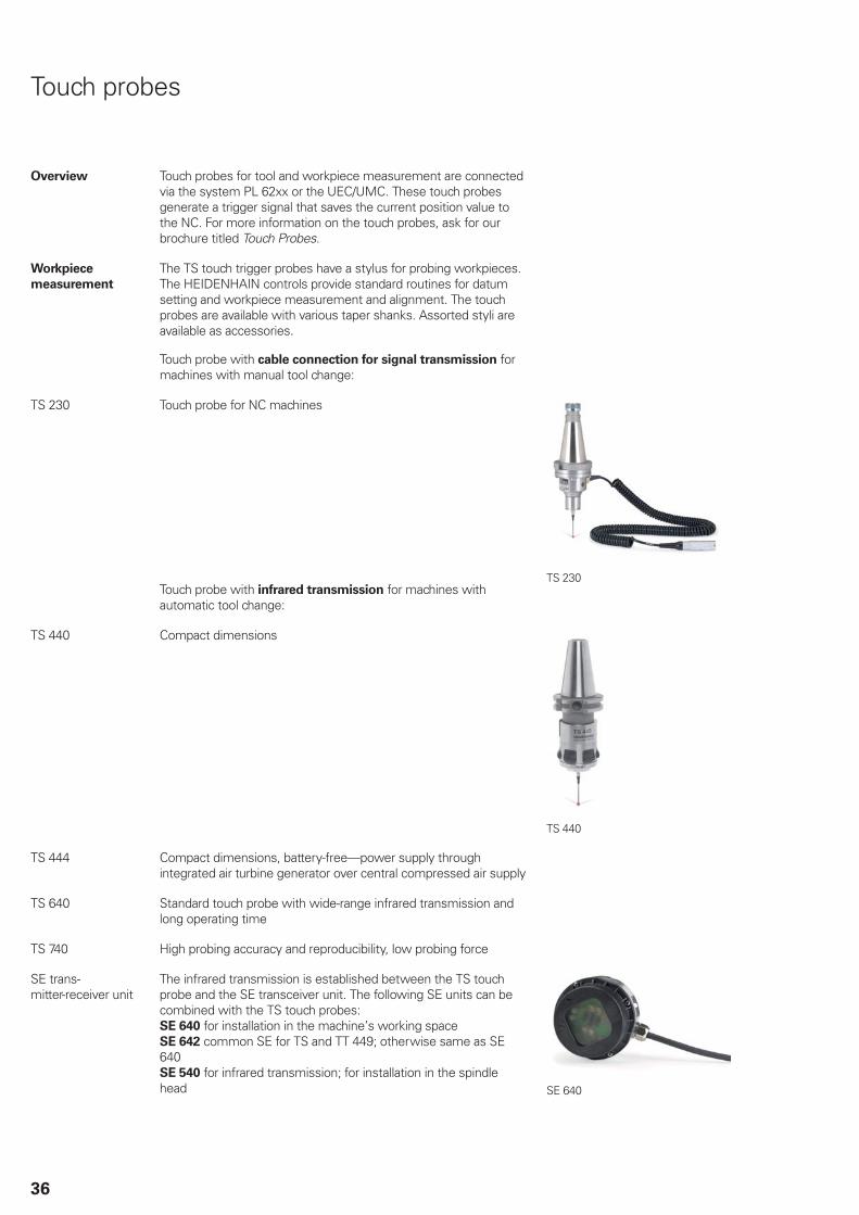
TS 230 Touch probe for NC machines
Touch probe with infrared transmission for machines withautomatic tool change:
TS 230
TS 440 Compact dimensions
TS 440
TS 444 Compact dimensions, battery-free—power supply throughintegrated air turbine generator over central compressed air supply
TS 640 Standard touch probe with wide-range infrared transmission andlong operating time
TS 740 High probing accuracy and reproducibility, low probing force
SE trans-mitter-receiver unit
The infrared transmission is established between the TS touchprobe and the SE transceiver unit. The following SE units can becombined with the TS touch probes: SE 640 for installation in the machine’s working spaceSE 642 common SE for TS and TT 449; otherwise same as SE640SE 540 for infrared transmission; for installation in the spindlehead SE 640
37
Tool
measurement
The touch probes for tool measurement from HEIDENHAINare suited for probing stationary or rotating tools directly on themachine. The iTNC 530 has standard routines for measuringlength and diameter of the tool as well as the individual teeth. TheiTNC 530 automatically saves the results of measurement in atool table. It is also possible to measure tool wear between twomachining steps. The iTNC 530 compensates the changed tooldimensions automatically for subsequent machining or replacesthe tool after a certain limit—as for example after tool breakage.
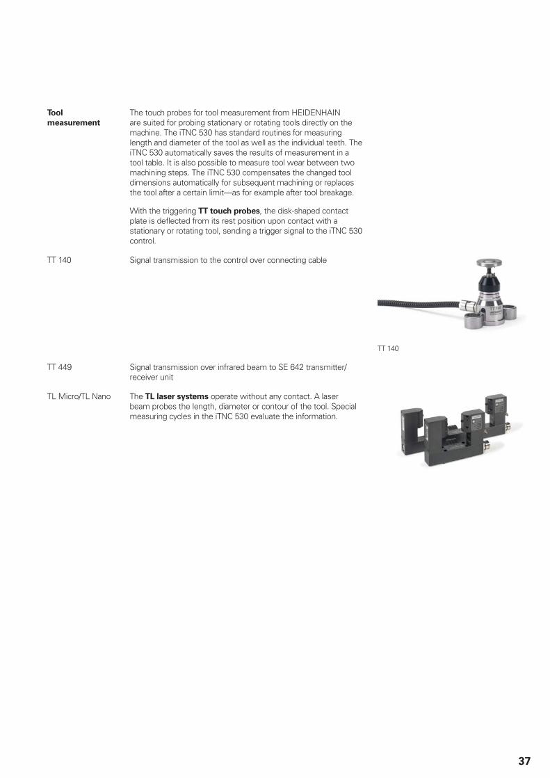
With the triggering TT touch probes, the disk-shaped contactplate is deflected from its rest position upon contact with astationary or rotating tool, sending a trigger signal to the iTNC 530control.
TT 140 Signal transmission to the control over connecting cable
TT 140
TT 449 Signal transmission over infrared beam to SE 642 transmitter/receiver unit
TL Micro/TL Nano The TL laser systems operate without any contact. A laserbeam probes the length, diameter or contour of the tool. Specialmeasuring cycles in the iTNC 530 evaluate the information.
38
Electronic handwheels
Overview The standard iTNC 530 supports the use of electronichandwheels.
HR 550 FS wireless handwheel, orHR 410 or HR 520 portable handwheel, orHR 130 panel-mounted handwheelUp to three HR 150 panel-mounted handwheels via HRA 110
Two handwheels or HRA handwheel adapters, one of whichcan be a HR 550 FS, can be connected to the MB machineoperating panel, the MC main computer or the PLB 6001 adapterfor HSCI.Handwheels with functional safety are cross-circuit proofthanks to the special permissive key logic.
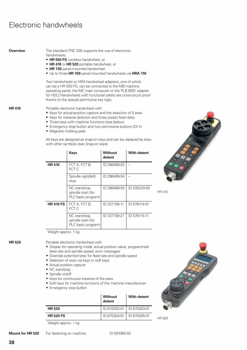
HR 410 Portable electronic handwheel withKeys for actual-position capture and the selection of 5 axesKeys for traverse direction and three preset feed ratesThree keys with machine functions (see below)Emergency stop button and two permissive buttons (24 V)Magnetic holding pads
All keys are designed as snap-on keys and can be replaced by keyswith other symbols (see Snap-on keys).
Keys Without
detent
With detent
FCT A, FCT B,FCT C
ID 296469-53 –
Spindle right/left/stop
ID 296469-54 –
HR 410
NC start/stop,spindle start (forPLC basic program)
ID 296469-55 ID 535220-05
FCT A, FCT B,FCT C
ID 337159-11 ID 578114-01HR 410 FS
NC start/stop,spindle start (forPLC basic program)
ID 337159-21 ID 578114-11
Weight approx. 1 kg
HR 410
HR 520 Portable electronic handwheel withDisplay for operating mode, actual position value, programmedfeed rate and spindle speed, error messagesOverride potentiometer for feed rate and spindle speedSelection of axes via keys or soft keysActual position captureNC start/stopSpindle on/offKeys for continuous traverse of the axesSoft keys for machine functions of the machine manufacturerEmergency stop button
Without
detent
With detent
HR 520 ID 670302-01 ID 670303-01
HR 520 FS ID 670304-01 ID 670305-01
Weight approx. 1 kgHR 520
Mount for HR 520 For fastening on machine ID 591065-02

39
HR 550 FS Electronic handwheel with wireless transmission. Display,operating elements and functions same as HR 520.
In addition:Functional safetyWireless transmission range up to 20 m (depending onenvironment)
HR 550 FS Without detent ID 598515-03With detent ID 606622-03
Replacement
battery
for HR 550 FS ID 623166-xx
HR 550 FS with HRA 551 FS
HRA 551 FS Handwheel mount for HR 550 FSFor docking the HR 550 FS on the machineIntegrated charger for HR 550 FSConnections to the control and the machineIntegrated transmitter/receiver unit
HRA 551 FS ID 731928-02Weight Approx. 1.0 kg
For more information, see the HR 550 FS Product Informationsheet.
Connecting cable For HR 410/
HR 520
For
HR 410 FS/
HR 520 FS
For HR 550 FS
with
HRA 551 FS
Connecting cable (spiral cable) to HR(3 m)
– ID 312879-01
Connecting cable with metal armor – ID 296687-xx
Connecting cable without metal armor ID 296467-xx
Adapter cable for HR/HRA to MC 1) ID 296466-xx
Extension cable to adapter cable 1) ID 281429-xx
Adapter cable for HRA to MC – – 2) ID 749368-xx
Extension cable to adapter cable – – 2) ID 749369-xx
Dummy plug for standard handwheels – – ID 271958-03
Dummy plug for handwheels with FS – ID 271958-05
1) For cable lengths up to 20 m between MB and HRA 551 FS2) For cable lengths up to 50 m between MB and HRA 551 FS
See also Cable overview on Page 45.

40
HR 130 Panel-mounted handwheel with ergonomic control knob. It is attached to the MB 7x0 or the TE 7x5 either directly or via anextension cable.
HR 130 Without detent ID 540940-03With detent ID 540940-01
Weight Approx. 0.7 kg
HR 130
HR 150 Panel-mounted handwheel with ergonomic control knob forconnection to the HRA 110 handwheel adapter.
HR 150 Without detent ID 540940-07With detent ID 540940-06
Weight Approx. 0.7 kg
HR 150
HRA 110 Handwheel adapter for connection of up to three HR 150 panel-mounted handwheels and two switches for axis selection andfor selecting the interpolation factor. The first two handwheelsare permanently assigned to axes 1 and 2. The third handwheelis assigned to the axes over a selection switch (accessory) or bymachine parameters. The position of the second selection switch(accessory) is evaluated by the PLC, for example to set the properinterpolation.
HRA 110 ID 261097-04Weight Approx. 1.5 kg
Step switch With turning knob and cable ID 270908-xx
HRA 110
Step switch
41
Industrial PC
IPC 6110
IPC 6120
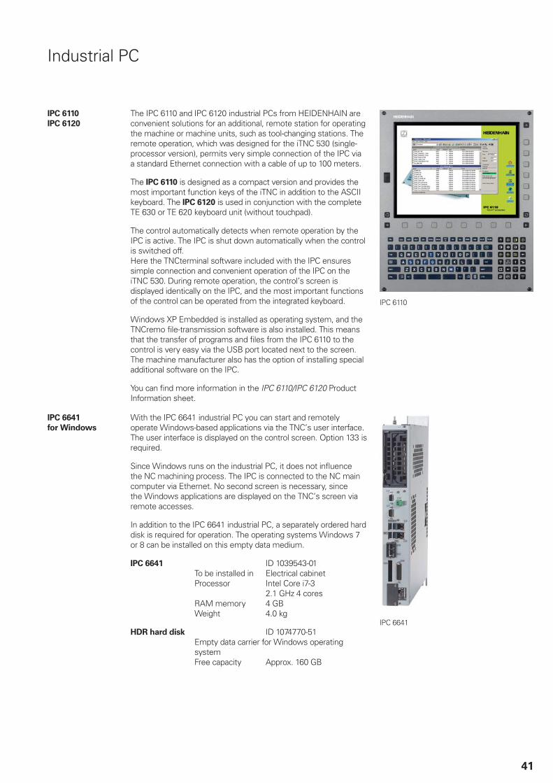
The IPC 6110 and IPC 6120 industrial PCs from HEIDENHAIN areconvenient solutions for an additional, remote station for operatingthe machine or machine units, such as tool-changing stations. Theremote operation, which was designed for the iTNC 530 (single-processor version), permits very simple connection of the IPC viaa standard Ethernet connection with a cable of up to 100 meters.
The IPC 6110 is designed as a compact version and provides themost important function keys of the iTNC in addition to the ASCIIkeyboard. The IPC 6120 is used in conjunction with the completeTE 630 or TE 620 keyboard unit (without touchpad).
The control automatically detects when remote operation by theIPC is active. The IPC is shut down automatically when the controlis switched off. Here the TNCterminal software included with the IPC ensuressimple connection and convenient operation of the IPC on theiTNC 530. During remote operation, the control’s screen isdisplayed identically on the IPC, and the most important functionsof the control can be operated from the integrated keyboard.
Windows XP Embedded is installed as operating system, and theTNCremo file-transmission software is also installed. This meansthat the transfer of programs and files from the IPC 6110 to thecontrol is very easy via the USB port located next to the screen.The machine manufacturer also has the option of installing specialadditional software on the IPC.
You can find more information in the IPC 6110/IPC 6120 ProductInformation sheet.
IPC 6110
IPC 6641
for Windows
With the IPC 6641 industrial PC you can start and remotelyoperate Windows-based applications via the TNC’s user interface.The user interface is displayed on the control screen. Option 133 isrequired.
Since Windows runs on the industrial PC, it does not influencethe NC machining process. The IPC is connected to the NC maincomputer via Ethernet. No second screen is necessary, sincethe Windows applications are displayed on the TNC’s screen viaremote accesses.
In addition to the IPC 6641 industrial PC, a separately ordered harddisk is required for operation. The operating systems Windows 7or 8 can be installed on this empty data medium.
IPC 6641 ID 1039543-01To be installed in Electrical cabinetProcessor Intel Core i7-3
2.1 GHz 4 coresRAM memory 4 GBWeight 4.0 kg
HDR hard disk ID 1074770-51Empty data carrier for Windows operatingsystemFree capacity Approx. 160 GB
IPC 6641

42
Snap-on keys for HR
Overview
The snap-on keys make it easy to replace the key symbols. In this way, the HR handwheel can be adapted to different requirements. Thesnap-on keys are available in packs of 5 keys.
Axis keys
Machinefunctions
Spindlefunctions
Other keys
43
Snap-on keys for control
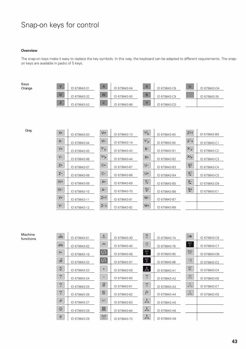
Overview
The snap-on keys make it easy to replace the key symbols. In this way, the keyboard can be adapted to different requirements. The snap-on keys are available in packs of 5 keys.
Machinefunctions
Keys

44
Other keys
Spindlefunctions

45
Cable overview
Control systems with CC; MC in operating panel
60m
3609
74-x
x (L
S x
87)
2984
29-x
x (L
B, L
F 18
3)29
8430
-xx
(LF
481)
3097
83-x
x
3101
99-x
x
3363
76-x
x
5587
14-x
x m
ax. 3
0m
3321
15-x
x
LC
LC x
83
60m
60m
VL
3238
97-x
x
LC x
83
RC
N 7
29R
CN
226
RC
N 2
28
3363
76-x
xLC
x83
KT
Y
5336
31-x
x m
ax. 9
m
3403
02-x
x28
9440
-xx
KT
Y
LB/L
S
60m
max
. 9m
2894
40-x
xV
L33
6847
-xx
60m
5336
31-x
x m
ax. 9
m
VL
3238
97-x
x
5096
67-x
x
1)
1m
1m
30m
RC
N 7
29R
CN
226
RC
N 2
28
2)
X50
0
HS
CI
X50
0
X50
2
PL
620x
PL
610x
2)
1)
6734
59-x
x m
ax. 2
0m
5336
27-x
x36
8330
-xx
5336
61-x
x m
ax. 1
6m
3) 4)
3)
4)
max
. 20m
max
. 12m
max
. 12m
3)
4)
3)
4)
3)
4)
CC
6x
xx
X15
A ..
. X18
AX
15B
... X
20B
*)
X20
1A ..
. X20
4AX
201B
... X
206B
*)X
502A
X50
0A
X50
2B*)
X50
0B*)
X51
A...
X54
AX
51B
...X
56B
*
30.0
7.20
13
HS
CI
X50
1
2x U
SB
X50
2
X50
2
HS
CI
7224
14-x
xM
1268
8144
-xx
HS
CI
HS
CI
X50
0
MC
7x
xx
TE
73
5/T
E 7
45
TE
72
0/T
E 7
30
MB
72
0
US
B 2
.0 3
5477
0-xx
US
B 1
.1 6
2477
5-xx
max
. 5m
max
. 20m
X60
X10
X50
2
2504
79-5
5
2504
79-6
0
X1
X3
X1
UM
C 1
1x
X50
2
X50
0
X15
...X
18
PL
C I
/0
1 V
PP
Posi
tio
n in
pu
ts
1 V
PP
Speed inputs
En
Dat
2.1
inte
rfac
e
Axe
s +
spin
dle
:
Axe
s: 6
0m
Vo
ltag
e co
ntr
olle
r 5
V36
8210
-01
Vo
ltag
e co
ntr
olle
r 5
V38
3951
-01
1 V
PP
1 V
PP
on
ly f
or
con
nec
tio
n o
f th
e K
TY
Ad
apte
r co
nn
ecto
r 54
4703
-01
for
spin
dle
(if
nec
essa
ry)
En
Dat
������ wit
h in
crem
enta
l sig
nal
s
Pure
ser
ial E
nD
at 2
.2
1 V
PP
*) C
Cs
wit
h 2
nd
co
ntr
olle
r b
oar
d
VL:
Ext
ensi
on
cab
le
–
fo
r se
par
atio
n p
oin
ts w
ith
co
nn
ecti
ng
cab
le
–
fo
r ex
ten
din
g e
xist
ing
co
nn
ecti
ng
cab
le
*) in
clu
ded
wit
h t
he
MC
(1,
5m)
**)
incl
ud
ed w
ith
th
e M
B (
0,5m
)
HS
CI t
ota
l len
gth
70
m
Cab
inet
rib
bo
n c
able
fo
r p
ots
**)
rib
bo
n c
able
fo
r sk
rib
bo
n c
able
fo
r sk
*)
*)
40 in
pu
ts24
ou
tpu
ts
PW
Mo
ut

46
Control systems with CC; MC in electrical cabinet
CC
6xx
x
X15
A ..
. X18
AX
15B
... X
20B
*)
X20
1A ..
. X20
4AX
201B
... X
206B
*)
60m
3097
83-x
x
3101
99-x
x
X14
1X
142
3363
76-x
x
60m
3363
76-x
xLC
x83
KT
Y
5336
31-x
x m
ax. 6
m
3403
02-x
x28
9440
-xx
KT
Y
LB/L
S
60m
max
. 9m
HS
CI
6188
93-x
x
625
901-
xxm
ax. 2
0m
2894
40-x
xV
L33
6847
-xx
60m
VL
3238
97-x
x
5096
67-x
x
1)
1mR
CN
729
RC
N 2
26R
CN
228
2)
X50
0A
MC
6xx
x
X24
9X
500
X50
2A
HS
CI
X50
0B**
*)
X50
2B**
*)
X50
2
HS
CI
X50
2
X50
0
PL
620x
PL
610x
2)
1)
US
B
HS
CI
6188
93-x
x
X50
0
X50
2
7224
14-x
xM
1268
8 14
4-xx
HS
CI
BF
76
0
BF
75
0
2xU
SB
TE
73
5 /
TE
74
5
US
B 2
.0 3
5477
0-xx
US
B 1
.1 6
2477
5-xx
max
. 5m
max
. 20m
US
B 2
.0 3
5477
0-xx
US
B 1
.1 6
2477
5-xx
max
. 5m
max
. 20m
3609
74-x
x (L
S x
87)
2984
29-x
x (L
B, L
F 18
3)29
8430
-xx
(LF
481)
max
. 20m
max
. 12m
max
. 12m
5587
14-x
x m
ax. 3
0m
3321
15-x
x
LC
LC x
83
60m
VL
3238
97-x
x
LC x
83
RC
N 7
29R
CN
226
RC
N 2
28
5336
31-x
x m
ax. 9
m
1m
30m
6734
59-x
x m
ax. 2
0m
5336
27-x
x36
8330
-xx
5336
61-x
x m
ax. 1
6m
3) 4)
3)
4)
3)
4)
3)
4)
3)
4)
X51
A...
X54
AX
51B
...X
56B
*
TE
72
0/T
E 7
30
MB
72
0
29.0
7.20
13X
502
X60
X10
2504
79-6
0
2504
79-5
5
X1
X3
X1
UM
C 1
1x
X50
0
X50
2
X15
...X
18
PL
C I
/0
1 V
PP
Posi
tio
n in
pu
ts
1 V
PP
1 V
PP
Speed inputs
En
Dat
2.1
inte
rfac
e
Axe
s +
spin
dle
:
Axe
s: 6
0m
Vo
ltag
e co
ntr
olle
r 5
V36
8210
-01
Vo
ltag
e co
ntr
olle
r 5
V38
3951
-01
1 V
PP
1 V
PP
on
ly f
or
con
nec
tio
n o
f th
e K
TY
Ad
apte
r co
nn
ecto
r 54
4703
-01
for
spin
dle
(if
nec
essa
ry)
***)
CC
s w
ith
2n
d c
on
tro
ller
bo
ard
cab
inet
En
Dat
������ wit
h in
crem
enta
l sig
nal
s
Pure
ser
ial E
nD
at 2
.2
VL:
Ext
ensi
on
cab
le
–
fo
r se
par
atio
n p
oin
ts w
ith
co
nn
ecti
ng
cab
le
–
fo
r ex
ten
din
g e
xist
ing
co
nn
ecti
ng
cab
le
*) in
clu
ded
wit
h t
he
BF
(1m
)
**)
incl
ud
ed w
ith
th
e M
B (
0,5m
)
HS
CI t
ota
l len
gth
70
m
rib
bo
n c
able
fo
r p
otsrib
bo
n c
able
fo
r sk
rib
bo
n c
able
fo
r p
ots
*)
**)
*)
40 in
pu
ts24
ou
tpu
ts
PW
Mo
ut

47
Control systems with UEC; MC in operating panel
UE
C 1
1x
X20
1 ...
X20
4 (U
EC
111
)X
502
X50
0
PL
C I
/O
X20
1 ...
X20
5 (U
EC
112
)X
201
... X
206
(UE
C 1
13)
X15
... X
18 (
UE
C 1
11)
X15
... X
19 (
UE
C 1
12)
X15
... X
20 (
UE
C 1
13)
12m
60m
3097
83-x
x
3101
99-x
x
3363
76-x
x
60m
3363
76-x
xLC
x83
KT
Y
5336
31-x
x m
ax. 6
m
3403
02-x
x28
9440
-xx
KT
Y
LB/L
S
60m
max
. 9m
2894
40-x
xV
L33
6847
-xx
60m
VL
3238
97-x
x
5096
67-x
x
1)
1mR
CN
729
RC
N 2
26R
CN
228
2)
X50
0
HS
CI
PL
610x
2)
1)
X80
... X
85
X50
1
2x U
SB
X50
2
X50
2
HS
CI
HS
CI
X50
2
7224
14-x
xM
1268
8144
-xx
HS
CI
HS
CI
3609
74-x
x (L
S x
87)
2984
29-x
x (L
B, L
F 18
3)29
8430
-xx
(LF
481)
max
. 20m
max
. 12m
max
. 12m
5587
14-x
x m
ax. 3
0m
3321
15-x
x
LC
LC x
83
60m
VL
3238
97-x
x
LC x
83
RC
N 7
29R
CN
226
RC
N 2
28
5336
31-x
x m
ax. 9
m
1m
30m
6734
59-x
x m
ax. 2
0m
5336
27-x
x36
8330
-xx
5336
61-x
x m
ax. 1
6m
3) 4)
3)
4)
3)
4)
3)
4)
3)
4)
X50
0
MC
7x
xx
TE
73
5 /
TE
74
5T
E 7
20
/TE
73
0
MB
72
0
29.0
7.20
13
US
B 2
.0 3
5477
0-xx
US
B 1
.1 6
2477
5-xx
max
. 5m
max
. 20m
X60
X10
2504
79-5
5
X1
X3
X1
1 V
PP
Posi
tio
n in
pu
ts
1 V
PP
1 V
PP
Speed inputs
En
Dat
2.1
inte
rfac
e
Axe
s +
spin
dle
:
Axe
s: 6
0m
Vo
ltag
e co
ntr
olle
r 5
V36
8210
-01
Vo
ltag
e co
ntr
olle
r 5
V38
3951
-01
1 V
PP
1 V
PP
on
ly f
or
con
nec
tio
n o
f th
e K
TY
Ad
apte
r co
nn
ecto
r 54
4703
-01
for
spin
dle
(if
nec
essa
ry)
Cab
inet
VL:
Ext
ensi
on
cab
le
–
fo
r se
par
atio
n p
oin
ts w
ith
co
nn
ecti
ng
cab
le
–
fo
r ex
ten
din
g e
xist
ing
co
nn
ecti
ng
cab
le
*) in
clu
ded
wit
h t
he
MC
(1,
5m)
**)
incl
ud
ed w
ith
th
e M
B (
0,5m
)
HS
CI t
ota
l len
gth
70
m
En
Dat
������ wit
h in
crem
enta
l sig
nal
s
Pure
ser
ial E
nD
at 2
.2
rib
bo
n c
able
fo
r p
ots
rib
bo
n c
able
fo
r sk
rib
bo
n c
able
fo
r sk
*)
**)
*)
40 in
pu
ts
24 o
utp
uts
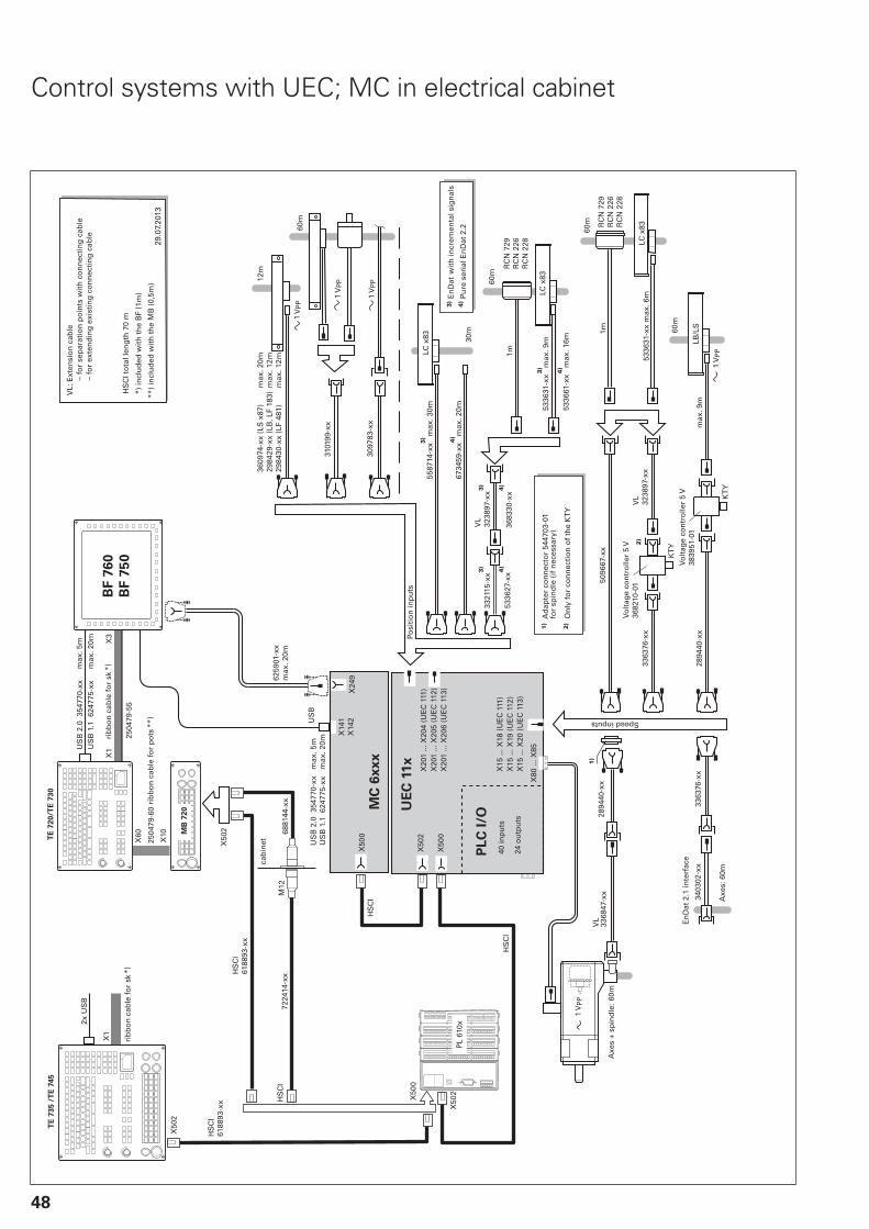
48
Control systems with UEC; MC in electrical cabinet
UE
C 1
1x
X20
1 ...
X20
4 (U
EC
111
)X
502
X50
0
PL
C I
/O
X20
1 ...
X20
5 (U
EC
112
)X
201
... X
206
(UE
C 1
13)
X15
... X
18 (
UE
C 1
11)
X15
... X
19 (
UE
C 1
12)
X15
... X
20 (
UE
C 1
13)
12m
60m
3097
83-x
x
3101
99-x
x
X14
1X
142
3363
76-x
x
60m
3363
76-x
xLC
x83
KT
Y
5336
31-x
x m
ax. 6
m
3403
02-x
x28
9440
-xx
KT
Y
LB/L
S
60m
max
. 9m
2894
40-x
xV
L33
6847
-xx
60m
VL
3238
97-x
x
5096
67-x
x
1)
1mR
CN
729
RC
N 2
26R
CN
228
2)
MC
6x
xx
X24
9X
500
HS
CI
X50
2
HS
CI
PL
610x
2)
1)
X50
0
X80
... X
85
5587
14-x
x m
ax. 3
0m
3321
15-x
x
LC
LC x
83
60m
VL
3238
97-x
x
LC x
83
RC
N 7
29R
CN
226
RC
N 2
28
5336
31-x
x m
ax. 9
m
1m
30m
6734
59-x
x m
ax. 2
0m
5336
27-x
x36
8330
-xx
5336
61-x
x m
ax. 1
6m
3) 4)
3)
4)
3)
4)
3)
4)
3)
4)
3609
74-x
x (L
S x
87)
2984
29-x
x (L
B, L
F 18
3)29
8430
-xx
(LF
481)
max
. 20m
max
. 12m
max
. 12m
29.0
7.20
13
HS
CI
6188
93-x
x
6259
01-x
xm
ax. 2
0m
US
B
HS
CI
6188
93-x
x
X50
2
7224
14-x
xM
1268
8144
-xx
HS
CI
BF
76
0
BF
75
0
2x U
SB
TE
73
5 /
TE
74
5
US
B 2
.0 3
5477
0-xx
US
B 1
.1 6
2477
5-xx
max
. 5m
max
. 20m
US
B 2
.0 3
5477
0-xx
US
B 1
.1 6
2477
5-xx
max
. 5m
TE
72
0/T
E 7
30
MB
72
0
X50
2
X60
X10
2504
79-6
0
max
. 20m
2504
79-5
5
X1
X3
X1
1 V
PP
Posi
tio
n in
pu
ts
1 V
PP
1 V
PP
Speed inputs
En
Dat
2.1
inte
rfac
e
Axe
s +
spin
dle
:
Axe
s: 6
0m
Vo
ltag
e co
ntr
olle
r 5
V36
8210
-01
Vo
ltag
e co
ntr
olle
r 5
V38
3951
-01
1 V
PP
1 V
PP
On
ly f
or
con
nec
tio
n o
f th
e K
TY
Ad
apte
r co
nn
ecto
r 54
4703
-01
for
spin
dle
(if
nec
essa
ry)
VL:
Ext
ensi
on
cab
le
–
fo
r se
par
atio
n p
oin
ts w
ith
co
nn
ecti
ng
cab
le
–
fo
r ex
ten
din
g e
xist
ing
co
nn
ecti
ng
cab
le
*) in
clu
ded
wit
h t
he
BF
(1m
)
**)
incl
ud
ed w
ith
th
e M
B (
0,5m
)
HS
CI t
ota
l len
gth
70
m
cab
inet
rib
bo
n c
able
fo
r p
otsrib
bo
n c
able
fo
r sk
rib
bo
n c
able
fo
r sk
*)
**)
*)
En
Dat
������ wit
h in
crem
enta
l sig
nal
s
Pure
ser
ial E
nD
at 2
.2
40 in
pu
ts
24 o
utp
uts

49
Measuring devices
X15
A ..
. X18
AX
15B
... X
20B
*)X
201A
... X
204A
X20
1B ..
. X20
6B*)
55m
3097
83-x
x
3101
99-x
x
X50
0A
X50
2A
X50
0B*)
X50
2B*)
3609
74-x
x (L
S x
87)
2984
29-x
x (L
B, L
F 18
3)29
8430
-xx
(LF
481)
max
. 20m
max
. 12m
max
. 12m
29.0
7.20
13
3101
28-x
x (L
B, L
F 18
3)31
0123
-xx
(LF
481)
3606
45-x
x (L
S x
87)
7359
94-x
x
6419
26-x
x67
9671
-xx
max
. 6m
max
. 55m
max
. 25m
7359
61-x
x
RC
N x
x10
/ En
Dat
22
RC
N x
x80
/ En
Dat
02
7359
94-x
x
5336
27-x
x67
9671
-xx
max
. 6m
max
. 55m
max
. 25m
7276
58-x
x
3321
15-x
x64
3450
-xx
max
. 20mR
CN
xx1
0 / E
nD
at 2
2
RC
N x
x80
/ En
Dat
02
LC x
15 /
En
Dat
22
5336
61-x
x m
ax. 6
m64
1926
-xx
5587
27-x
xLC
x8/
3 / E
nD
at 0
2
5096
67-x
x53
3631
-xx
max
. 9m
max
. 55m
6734
59-x
x
5336
27-x
x53
3661
-xx
max
. 6m
5587
14-x
x
3321
15-x
x53
3631
-xx
max
. 9m
max
. 55m
LC 2
11LC
x15
/ E
nD
at 2
2
max
. 25m
LC 2
81LC
x83
/ E
nD
at 0
2
UE
C 1
xxU
MC
1xx
CC
6xx
x
5096
67-x
x64
3450
-xx
max
. 20m
max
. 55m
max
. 30mmax
. 9m
max
. 20m
max
. 55m
max
. 20m
max
. 55m
max
. 20m
max
. 55m
1 V
PP
Position inputs
1 V
PP
1 V
PP
*) C
Cs
wit
h 2
nd
co
ntr
olle
r b
oar
d
Speed inputs
Vo
ltag
e co
ntr
olle
r 5
V36
8210
-02
Vo
ltag
e co
ntr
olle
r 5
V36
8210
-02

50
Inverter system
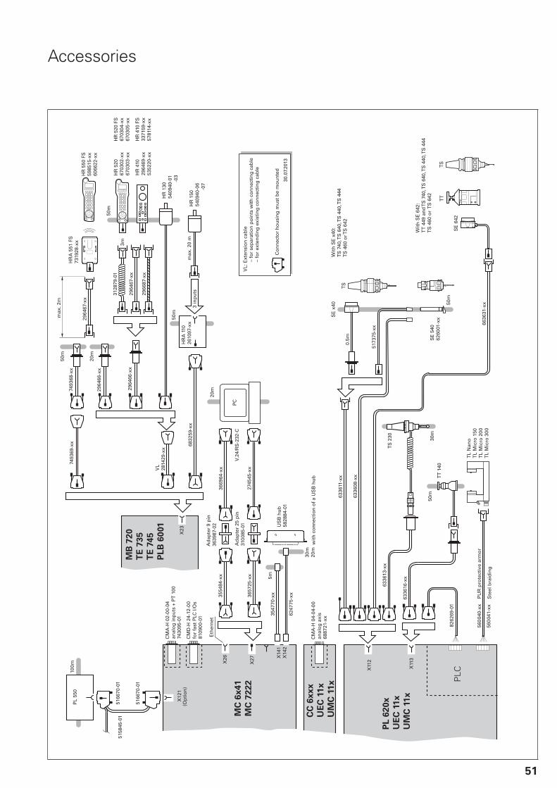
51
Accessories
3657
25-x
x
MC
6x
41
MC
72
22
274
545-
xx
20m
PC
6336
16-x
x
50m
TT
140
30m
TS
230
6336
11-x
x
6336
13-x
x
X27
3554
84-x
x36
6964
-xx
3547
70-x
xX
141
X14
2
5m
6247
75-x
x
30m
20m
5158
45-0
1
30.0
7.20
13
50m
0.5m
PL
550
100m
V.24
/RS
-232
-C
5166
70-0
1
5166
70-0
1
X12
1
5173
75-x
x
X26
5600
40-x
x
8262
69-0
1
X11
2
X11
3
5600
41-x
x
PLC
PL
62
0x
UE
C 1
1x
UM
C 1
1x
6336
08-x
x
TS
SE
x40
SE
540
6260
01-x
x
TL
Nan
o
TL
Mic
ro 1
50
TL
Mic
ro 2
00
TL
Mic
ro 3
00
TT
6636
31-x
x
SE
642
X23
MB
72
0
TE
73
5
TE
74
5
PL
B 6
001
50m
max
. 20
m
VL
2814
29-x
x
2964
66-x
x
6832
59-x
xH
RA
110
2610
97-x
x
50m
2966
87-x
x
2964
67-x
x
3m
HR
150
5409
40-0
6
-0
7
HR
130
5409
40-0
1
-0
3HR
410
2964
69-x
x53
5220
-xx
3128
79-0
1 H
R 5
2067
0302
-xx
6703
03-x
x
2964
67-x
x
2964
66-x
x
20m
HR
550
FS
5985
15-x
x60
6622
-xx
max
. 2m
HR
A 5
51 F
S73
1928
-xx
7493
68-x
x
50m
7493
69-x
x
TS
6887
21-x
x
CC
6x
xx
UE
C 1
1x
UM
C 1
1x
CM
A-H
04-
04-0
0
HR
410
FS
3371
59-x
x57
8114
-xx
HR
520
FS
67
0304
-xx
6703
05-x
x
7430
95-0
1
CM
A-H
02-
00-0
4
8109
00-0
1
CM
D-H
24-
12-0
0
Ad
apte
r 25
pin
3100
85-0
1V
L: E
xten
sio
n c
able
– f
or
sep
arat
ion
po
ints
wit
h c
on
nec
tin
g c
able
– f
or
exte
nd
ing
exi
stin
g c
on
nec
tin
g c
able
Ad
apte
r 9
pin
3639
87-0
2
Co
nn
ecto
r h
ou
sin
g m
ust
be
mo
un
ted
US
B h
ub
5828
84-0
1
PU
R p
rote
ctiv
e ar
mo
r
Ste
el b
raid
ing
wit
h c
on
nec
tio
n o
f a
US
B h
ub
3 in
pu
ts
anal
og
axi
s
Eth
ern
et
(Op
tio
n)
anal
og
inp
uts
+ P
T 1
00
for
fast
PLC
I/O
s
Wit
h S
E 6
42:
TT
449
an
d T
S 7
40, T
S 6
40, T
S 4
40, T
S 4
44T
S 4
60 o
r T
S 6
42
Wit
h S
E x
40:
TS
740
, TS
640
, TS
440
, TS
444
TS
460
or T
S 6
42

52
Technical description
Digital control design
Uniformly digital In the uniformly digital control design from HEIDENHAIN, allcomponents are connected to each other via purely digitalinterfaces: The control components are connected via HSCI
(HEIDENHAIN Serial Controller Interface), the new real-timeprotocol from HEIDENHAIN for Fast Ethernet, and the encodersare connected via EnDat 2.2, the bidirectional interface fromHEIDENHAIN. This achieves a high degree of availability for theentire system. It can be diagnosed and is immune to noise—fromthe main computer to the encoder. These outstanding propertiesof the uniformly digital design from HEIDENHAIN guarantee notonly very high accuracy and surface quality, but rapid traversespeeds as well. Please refer to the Uniformly Digital TechnicalInformation sheet for more detailed information.
HSCI HSCI, the HEIDENHAIN Serial Controller Interface, connects themain computer, controller(s) and other control components. HSCIis based on 100BaseT Ethernet hardware. A special interfacecomponent developed by HEIDENHAIN makes short cycle timesfor data transfer possible.
Main advantages of the control design with HSCI:
Hardware platform for flexible and scalable control system (e.g.local axis systems)High noise immunity due to digital communication betweencomponentsHardware basis for the implementation of “functional safety”Simpler wiring (initial operation, configuration)Inverters remain connected via proven PWM interfaceGreater cable lengths in the entire system (HSCI up to 70 m)Number of control loops can be increased (up to 18 axes andalternatively two spindles)More PLC inputs and outputsController units can be installed elsewhere
CC or UEC controller units, up to nine PL 6000 PLC input/outputmodules, and machine operating panels (such as the MB 720 fromHEIDENHAIN) can be connected to the serial HSCI bus of the MCmain computer. The HR handwheel is connected directly to themachine operating panel. The combination of visual display unitand main computer is especially advantageous if the computeris housed in the operating panel. All that is required then is thepower supply and an HSCI line to the controller in the electricalcabinet.
The maximum permissible number of individual HSCI participantsis listed below.
HSCI components Maximum number
MC HSCI master 1 in the system
CC, UEC, UMC HSCI slave 4 drive-control motherboards (distributed to CC, UEC, UMCas desired)
MB, PLB 6001 HSCI slave 2 in the system
PLB 61xx, PLB 62xx HSCI slave 7 in the system
HR On MB orPLB 6001
2 in the system (of which only one HR 550 FS)
PLD-H-xx-xx FS In PLB 6xxx FS 10 in the system
PLD-H-xx-xx, PLA-H-xx-xx In PLB 6xxx 25 in the system
Total maximum of1000 inputs/outputs

53
Functional safety
Basic principle Controls from HEIDENHAIN with functional safety meetsafety integrity level 2 (SIL 2) as per the EN 61 508 standard, aswell as performance level d, category 3, as per EN ISO 13 849-1(which replaced EN 954-1). These standards describe theassessment of safety-related systems, for example based on thefailure probabilities of integrated components and subsystems.This modular approach helps the manufacturers of safety-relatedsystems to implement their systems, because they can beginwith subsystems that have already been qualified. Safety-relatedposition encoders, the iTNC 530 control and functional safetyaccommodate this concept. Two redundant safety channels thatwork independently of each other are the foundation for controlswith functional safety. All safety-relevant signals are captured,processed and output via two channels. Errors are detected bymutual comparison of the states and data in the two channels. Inthis way, the occurrence of just one fault in the control does notlead to the safety functions being incapacitated.
Structure The safety-related controls from HEIDENHAIN have a dual-channeldesign with mutual monitoring. The SPLC (safety-related PLCprogram) and SKERN (safe core software) processes are the basisof the two redundant systems. The two software processes runon the MC main computer (CPU) and CC controller unit (DSP)components. The dual-channel structure of the MC and CC isalso used in the PLB 6xxx FS input/output systems and theMB 7xx FS machine operating panel. This means that all safety-relevant signals (e.g. permissive buttons and keys, door contacts,emergency stop button) are captured via two channels, and areevaluated independently of each other by the MC and CC. TheMC and CC use separate channels to also address the powermodules, and to stop the drives in case of an error.
Components In systems with functional safety, certain hardware componentsassume safety-relevant tasks. Systems with FS may consist ofonly those safety-relevant components, including their variants,which HEIDENHAIN has approved for use! Control components with functional safety are recognizable by thesuffix FS after the model designation, e.g. MB 720 FS.
MB and TE An MB machine operating panel with FS is indispensable forsystems with functional safety. Only on such a machine operatingpanel do all keys have a dual-channel design. Axes can be movedwithout additional permissive keys.
PLB In systems with functional safety, a combination of hardware (FSand standard) is possible, but a PLB 62xx FS is essential.
HR FS handwheels are required in systems with functional safetybecause only they have the required cross-circuit-proof permissivebuttons.
For a current list of components approved for FS, see theFunctional Safety FS Technical Manual.
54
Safety functions The following safety functions are integrated in the hardware andsoftware:
Safe stop reactions (SS0, SS1, SS2)Safe torque off (STO)Safe operating stop (SOS)Safely limited speed (SLS)Safely limited position (SLP)Safe brake control (SBC)Safe operating modes in accordance with EN 12 417– Operating mode 1: Automated or production mode– Operating mode 2: Set-up mode– Operating mode 3: Manual intervention– Operating mode 4: Advanced manual intervention, process
monitoring
Please note: The complete feature content is not yet available for all machinetypes with functional safety. Before planning a machine withfunctional safety, please inform yourself of whether the currentscope of features suffices for your machine design.
Activation of
functional safety
If the control identifies a PLB 62xx FS in the system duringbooting, functional safety is activated.
In this case, it is essential that the following prerequisites befulfilled:
Functional safety versions of safety-related control components(e.g. MB 720 FS, TE 735 FS, HR 550 FS)Safety-related SPLC programConfiguration of safe machine parametersWiring of the machine for systems with functional safety
Functional safety cannot be activated or deactivated by parameter.
More information For more information on the topic of functional safety, refer tothe Technical Information documents Safety-Related ControlTechnology for Machine Tools and Safety-Related PositionEncoders. For details, see the Functional Safety FS Technical Manual. Yourcontact person at HEIDENHAIN will be glad to answer anyquestions concerning controls with functional safety.

55
Operating system
HEROS 5 The iTNC 530 works with the real-time operating systemHEROS 5 (HEIDENHAIN Real-time Operating System). This future-oriented operating system features powerful functions:
Display of PDF files. Drawings, work instructions, etc. can beopened directly on the control.Direct Internet access from the iTNC 530 thanks to theintegrated browser.You can open various file formats directly on the iTNC 530 andalso edit some of them with the appropriate editors:– Text files (.txt, .ini)– Graphic files (.gif, .bmp, .jpg, .png)– Tables (.xls, .csv)– Internet files (.html)Standardized display format for operating system dialogs

56
Axes
Linear axes The iTNC 530 can control the linear axes X, Y, Z as well as U, V, W,depending on the version.
Display and programming
–99 999.9999 to +99 999.9999 [mm]
Feed rate in mm/min relative to the workpiece contour, or mm perspindle revolution
Feed rate override: 0% to 150%
Maximum feed rate:
60000 min –1
Screw pitch [mm]No. of motor pole pairs
Traverse range –99 999.9999 to +99 999.9999 [mm]
The machine tool builder defines the traverse range. The user canset additional limits to the traverse range if he wishes to reducethe working space. Three different traverse ranges can be defined(selection by PLC).
Rotary axes The iTNC 530 can control the rotary axes A, B and C. Special PLCfunctions are available for rotary axes with Hirth coupling.
Display and programming
0° to 360° or –99 999.9999 to +99 999.9999 [°]
Feed rate in degrees per minute [°/min]
Traverse range –99 999.9999 to +99 999.9999 [°]
The machine tool builder defines the traverse range. The user canset additional limits to the traverse range if he wishes to reducethe working space. Three different traverse ranges can be defined(selection by PLC).
Free rotation For milling-turning operations, the rotary axis can be started viathe PLC with a defined feed rate. For functions specific to milling/turning machines, see Turning operations.
Cylindrical surface
interpolation
(option 8)
A contour defined in the working plane is machined on a cylindricalsurface.

57
Tilting the
working plane
(option 8)
The iTNC 530 has special coordinate transformation cycles forcontrolling swivel heads and tilting tables. The offset of the tiltingaxes and the tool lengths are compensated by the TNC.
The TNC can manage more than one machine configuration (e.g.different swivel heads). The machine configurations are switchedvia the PLC. The change in the dimensions of the swivel head ortilting table caused by a rise in temperature can be compensatedby the iTNC 530.
Tilting tableSwivel head
5-axis machining
(option 9)
Tool Center Point Management (TCPM) The offset of the tilting axes is compensated so that the tooltip remains on the contour. Handwheel commands can also besuperimposed during machining without moving the tool tip fromthe programmed contour.
Synchronized
axes
Synchronized axes move in synchronismand are programmed with the same axisdesignation.
With HEIDENHAIN controls, parallelaxis systems (gantry axes) such as onportal-type machines or tilting tablescan be moved synchronously to eachother through high-accuracy and dynamicposition control.
With gantry axes more than one slave axiscan be assigned to one master gantry axis.They may also be distributed to severalcontroller units.
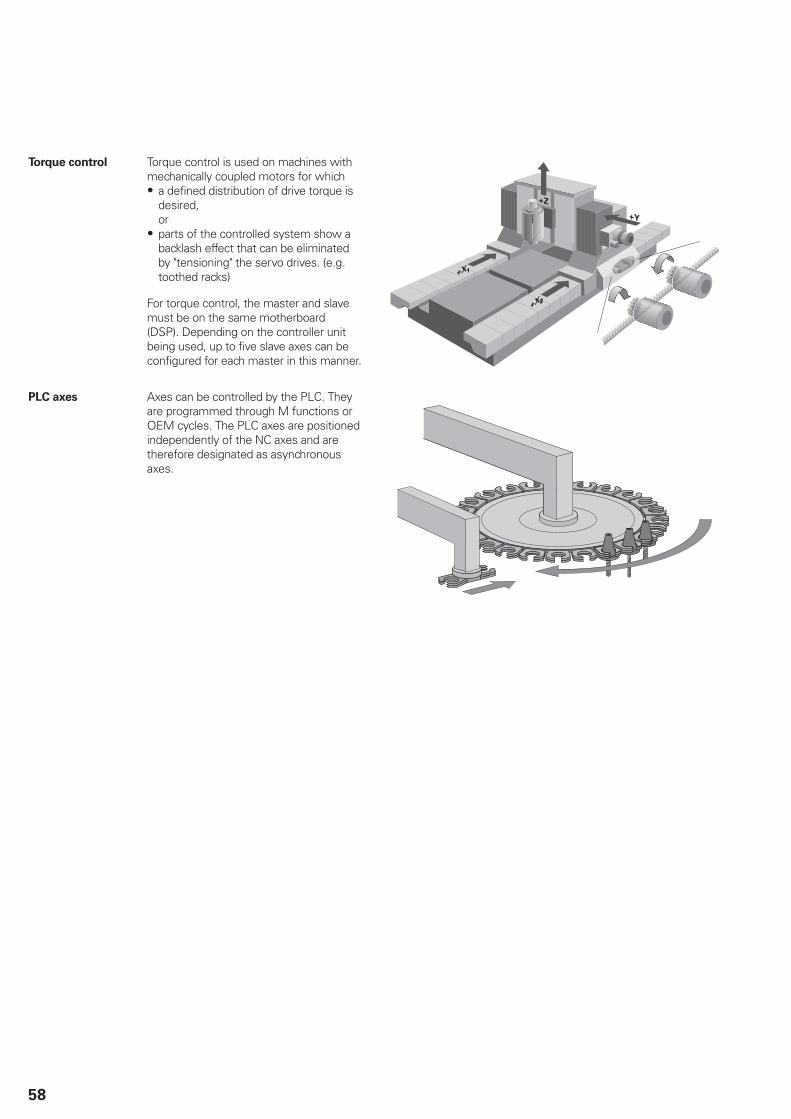
58
Torque control Torque control is used on machines withmechanically coupled motors for which
a defined distribution of drive torque isdesired, orparts of the controlled system show abacklash effect that can be eliminatedby "tensioning" the servo drives. (e.g.toothed racks)
For torque control, the master and slavemust be on the same motherboard(DSP). Depending on the controller unitbeing used, up to five slave axes can beconfigured for each master in this manner.
PLC axes Axes can be controlled by the PLC. Theyare programmed through M functions orOEM cycles. The PLC axes are positionedindependently of the NC axes and aretherefore designated as asynchronousaxes.

59
Spindle
Overview The iTNC 530 contouring control is used in connection with theHEIDENHAIN inverter systems with field-oriented control. As analternative, an analog nominal speed value can be output.
Controller unit With the CC controller units and the UEC/UMC inverters, a PWMbasic frequency can be set for each controller assembly (e.g.4 kHz). Possible basic frequencies are 3.33 kHz, 4 kHz or 5 kHz.The Double Speed option (option 49) can double this frequencyfor high-speed spindles (e.g. 8 kHz for HF spindles). See TechnicalManual.
Controller groups For example with CC 6106 1: X51 + X52 2: X53 + X54 3: X55 + X56
Maximum spindle
speed
The maximum spindle speed is calculated as follows:
nmax =
fPWM = PWM frequency in HzNPP = No. of pole pairs
Operating mode
switchover
For controlling the spindle (e.g. for wye/delta connection), twoparameter sets can be stored. You can switch between the twoparameter sets in the PLC.
Position-
controlled spindle
The position of the spindle is monitored by the control.
Encoder HEIDENHAIN rotary encoder with sinusoidal voltage signals (1 VPP)or EnDat interface.
Tapping There are special cycles for tapping with or without floating tapholder. For tapping without floating tap holder, the spindle must beoperated under position control.
Oriented spindle
stop
With a position-controlled spindle, the spindle can be positionedexactly to 0.1°.
Spindle override 0 to 150%
Gear ranges A specific nominal speed can be defined for each of the eight gearranges. The gear code is output via the PLC.
Second spindle Up to two spindles can be alternately controlled. You can switchfrom spindle 1 to spindle 2 through the PLC. Because the secondspindle is controlled instead of an axis, the number of availableaxes is reduced by one.
Milling-head
change
The iTNC 530 can manage various milling-head descriptions. Youprogram the milling-head change in the integrated PLC.

60
Encoders
Overview For speed and position control of the axes and spindle,HEIDENHAIN offers both incremental and absolute encoders.
Incremental
encoders
Incremental encoders have as measuring standard a gratingconsisting of alternate lines and spaces. Relative movementbetween the scanning head and the scale causes output ofsinusoidal scanning signals. The measured value is calculated fromthese signals.
Reference mark When the machine is switched on, the machine axes need totraverse a reference mark to establish an accurate connectionbetween measured value and machine position. For encoderswith distance-coded reference marks, the maximum travel untilautomatic reference mark evaluation for linear encoders is only20 mm or 80 mm, depending on the model, or 10° or 20° for angleencoders.
Reference markevaluation
The routine for traversing the reference marks can also be startedfor specific axes via the PLC during operation (reactivation ofparked axes).
Output signals Incremental encoders with sinusoidal output signals with levels1 VPP are suitable for connection to HEIDENHAIN numerical
controls.
Absolute
encoders
With absolute encoders, the position information is containedin several coded tracks. Thus, an absolute reference is availableimmediately after switch-on. Reference-mark traverse is notnecessary. Additional incremental signals are output for highlydynamic control loops.
EnDat interface The iTNC 530 features the serial EnDat 2.2 interface (includesEnDat 2.1) for the connection of absolute encoders.
Note: The EnDat interface on HEIDENHAIN encoders differs inits pin assignment from the interface on Siemens motors withintegrated absolute ECN/EQN rotary encoders. Special adaptercables are available.
Encoder inputs Incremental and absolute linear, angle or rotary encoders fromHEIDENHAIN can be connected to all position encoder inputs ofthe controller unit.
Incremental and absolute rotary encoders from HEIDENHAIN canbe connected to all speed encoder inputs of the controller unit.
Input frequency1)Inputs Signal level/
Interface1)
Position Shaft speed
Incremental signals 1 VPP 33 kHz/350 kHz 350 kHz
Absolute position valuesIncremental signals
EnDat 2.22)/021 VPP
– 33 kHz/350 kHz
– 350 kHz
Absolute position values EnDat 2.22)/22 – –
1) Switchable2) Includes EnDat 2.1
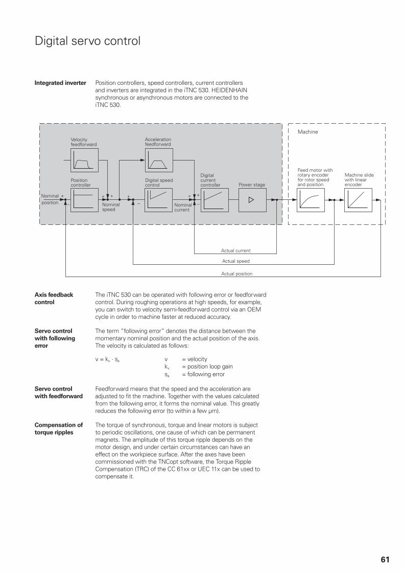
61
Digital servo control
Integrated inverter Position controllers, speed controllers, current controllersand inverters are integrated in the iTNC 530. HEIDENHAINsynchronous or asynchronous motors are connected to theiTNC 530.
Axis feedback
control
The iTNC 530 can be operated with following error or feedforwardcontrol. During roughing operations at high speeds, for example,you can switch to velocity semi-feedforward control via an OEMcycle in order to machine faster at reduced accuracy.
Servo control
with following
error
The term “following error” denotes the distance between themomentary nominal position and the actual position of the axis.The velocity is calculated as follows:
v = velocitykv = position loop gain
v = kv · sa
sa = following error
Servo control
with feedforward
Feedforward means that the speed and the acceleration areadjusted to fit the machine. Together with the values calculatedfrom the following error, it forms the nominal value. This greatlyreduces the following error (to within a few μm).
Compensation of
torque ripples
The torque of synchronous, torque and linear motors is subjectto periodic oscillations, one cause of which can be permanentmagnets. The amplitude of this torque ripple depends on themotor design, and under certain circumstances can have aneffect on the workpiece surface. After the axes have beencommissioned with the TNCopt software, the Torque RippleCompensation (TRC) of the CC 61xx or UEC 11x can be used tocompensate it.
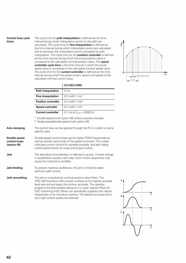
62
Control loop cycle
times
The cycle time for path interpolation is defined as the timeinterval during which interpolation points on the path arecalculated. The cycle time for fine interpolation is defined asthe time interval during which interpolation points are calculatedthat lie between the interpolation points calculated for pathinterpolation. The cycle time for the position controller is definedas the time interval during which the actual position value iscompared to the calculated nominal position value. The speed
controller cycle time is the time interval in which the actualspeed value is compared to the calculated nominal speed value.The cycle time for the current controller is defined as the timeinterval during which the actual current value is compared to thecalculated nominal current value.
CC/UEC/UMC
Path interpolation 3 ms
Fine interpolation 0.2 ms/0.1 ms1)
Position controller 0.2 ms/0.1 ms2)
Speed controller 0.2 ms/0.1 ms1)
Current controller 0.1 ms at fPWM = 5000 Hz
1) Double-speed (with option 49) without position encoder2) Single-speed/double-speed (with option 49)
Positio
n
Time
Axis clamping The control loop can be opened through the PLC in order to clampspecific axes.
Double-speed
control loops
(option 49)
Double-speed control loops permit higher PWM frequencies aswell as shorter cycle times of the speed controller. This makesimproved current control for spindles possible, and also highercontrol performance for linear and torque motors.
Jerk The derivative of acceleration is referred to as jerk. A linear changein acceleration causes a jerk step. Such motion sequences maycause the machine to oscillate.
Jerk limiting To prevent machine oscillations, the jerk is limited to attainoptimum path control.
Jerk smoothing The jerk is smoothed by nominal position value filters. TheiTNC 530 therefore mills smooth surfaces at the highest possiblefeed rate and yet keeps the contour accurate. The operatorprograms the permissible tolerance in a cycle. Special filters forHSC machining (HSC filters) can specifically suppress the naturalfrequencies of an individual machine. The desired accuracy and avery high surface quality are attained.
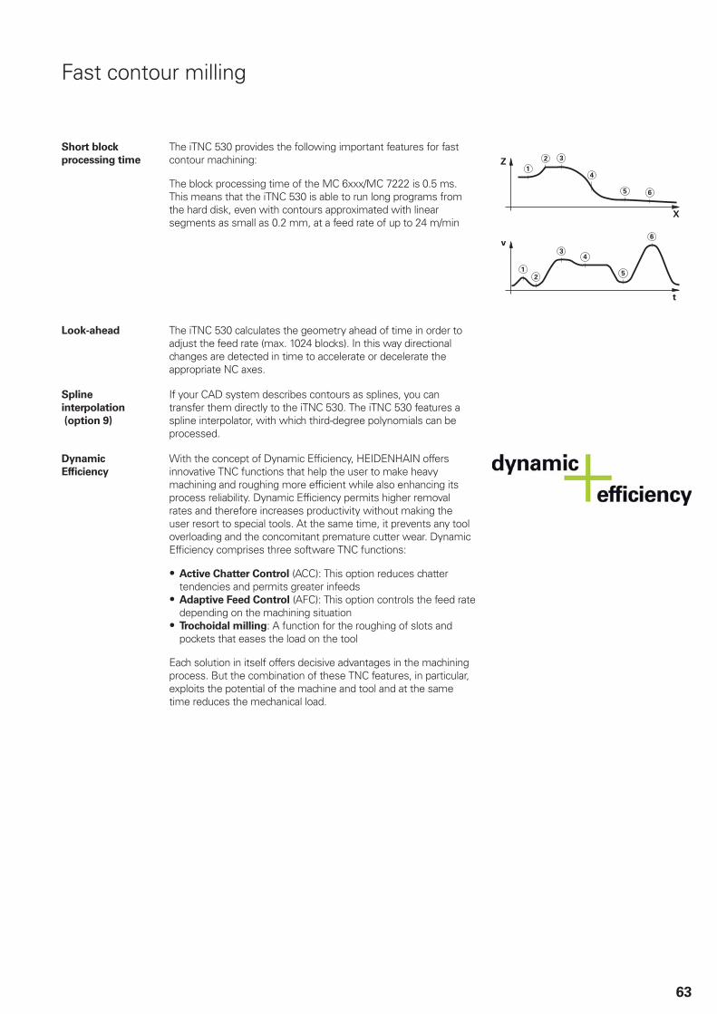
63
Fast contour milling
Short block
processing time
The iTNC 530 provides the following important features for fastcontour machining:
The block processing time of the MC 6xxx/MC 7222 is 0.5 ms.This means that the iTNC 530 is able to run long programs fromthe hard disk, even with contours approximated with linearsegments as small as 0.2 mm, at a feed rate of up to 24 m/min
Look-ahead The iTNC 530 calculates the geometry ahead of time in order toadjust the feed rate (max. 1024 blocks). In this way directionalchanges are detected in time to accelerate or decelerate theappropriate NC axes.
Spline
interpolation
(option 9)
If your CAD system describes contours as splines, you cantransfer them directly to the iTNC 530. The iTNC 530 features aspline interpolator, with which third-degree polynomials can beprocessed.
Dynamic
Efficiency
With the concept of Dynamic Efficiency, HEIDENHAIN offersinnovative TNC functions that help the user to make heavymachining and roughing more efficient while also enhancing itsprocess reliability. Dynamic Efficiency permits higher removalrates and therefore increases productivity without making theuser resort to special tools. At the same time, it prevents any tooloverloading and the concomitant premature cutter wear. DynamicEfficiency comprises three software TNC functions:
Active Chatter Control (ACC): This option reduces chattertendencies and permits greater infeedsAdaptive Feed Control (AFC): This option controls the feed ratedepending on the machining situationTrochoidal milling: A function for the roughing of slots andpockets that eases the load on the tool
Each solution in itself offers decisive advantages in the machiningprocess. But the combination of these TNC features, in particular,exploits the potential of the machine and tool and at the sametime reduces the mechanical load.
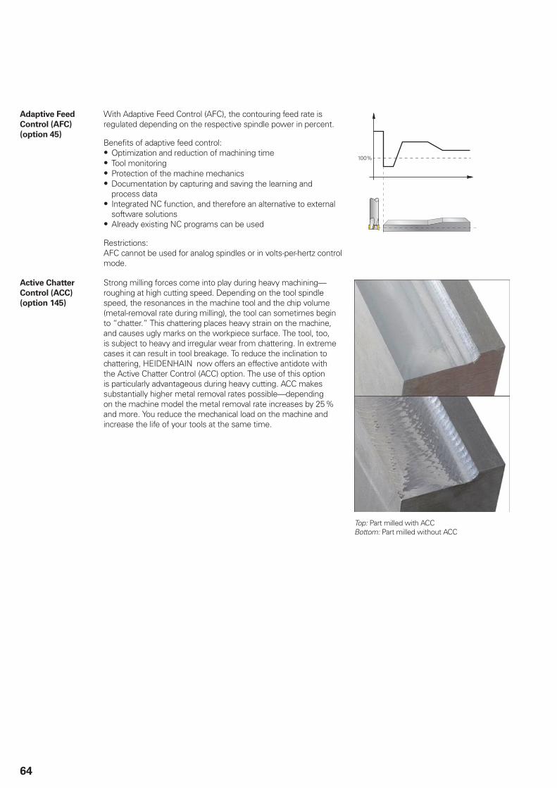
64
Adaptive Feed
Control (AFC)
(option 45)
With Adaptive Feed Control (AFC), the contouring feed rate isregulated depending on the respective spindle power in percent.
Benefits of adaptive feed control:Optimization and reduction of machining timeTool monitoringProtection of the machine mechanicsDocumentation by capturing and saving the learning andprocess dataIntegrated NC function, and therefore an alternative to externalsoftware solutionsAlready existing NC programs can be used
Restrictions: AFC cannot be used for analog spindles or in volts-per-hertz controlmode.
100%
Active Chatter
Control (ACC)
(option 145)
Strong milling forces come into play during heavy machining—roughing at high cutting speed. Depending on the tool spindlespeed, the resonances in the machine tool and the chip volume(metal-removal rate during milling), the tool can sometimes beginto “chatter.” This chattering places heavy strain on the machine,and causes ugly marks on the workpiece surface. The tool, too,is subject to heavy and irregular wear from chattering. In extremecases it can result in tool breakage. To reduce the inclination tochattering, HEIDENHAIN now offers an effective antidote withthe Active Chatter Control (ACC) option. The use of this optionis particularly advantageous during heavy cutting. ACC makessubstantially higher metal removal rates possible—dependingon the machine model the metal removal rate increases by 25%and more. You reduce the mechanical load on the machine andincrease the life of your tools at the same time.
Top: Part milled with ACC Bottom: Part milled without ACC

65
Monitoring functions
Description During operation the control monitors:Amplitude of the encoder signalsEdge separation of the encoder signalsAbsolute position for encoders with distance-coded referencemarksCurrent position (following error monitoring)Actual path traversed (movement monitoring)Position deviation at standstillNominal speed valueChecksum of safety-related functionsSupply voltageBuffer battery voltageOperating temperature of the MC and CPURun time of the PLC programMotor current and temperatureTemperature of power moduleDC-link voltage
With EnDat 2.2 encoders:CRC checksum of the position valueEnDat alarm Error1 EnDat status alarm register (0xEE)EnDat alarm Error2Edge speed of 5 μsTransmission of the absolute position value on the time grid
In the case of hazardous errors, an EMERGENCY STOP messageis sent to the external electronics via the control-is-ready output,and the axes are brought to a stop. The correct connection of theiTNC 530 in the machine’s EMERGENCY STOP loop is checkedwhen the control system is switched on. In the event of an error,the control displays a message in plain language.
Dynamic Collision
Monitoring (DCM)
(option 40)
The TNC features a Dynamic Collision Monitoring (DCM) softwareoption for cyclically monitoring the working space of the machinefor possible collisions with machine components. The machinemanufacturer must define three-dimensional collision objectswithin the working space of the machine that are to be monitoredby the TNC during all machine motions, including those madeby swivel heads and tilting tables. If two objects monitoredfor collision come within a defined distance of each other, theTNC outputs an error message. At the same time, the machinecomponents concerned are shown in red color in the machinedisplay. Dynamic collision monitoring is active in both the manualoperating modes as well as the machine operating modes, and isindicated by a symbol in the operating mode display.
Please note:Only the machine manufacturer can define collision objects(including clamping fixtures).Collisions between machine components (such as swivel heads)and the workpiece cannot be detected.In servo-lag operation (no feedforward), an oversize must betaken into account for the collision objects.Checking for collision is not possible in the Test Run mode.
Collision monitoring also protects fixtures and tool carriers fromcollisions. These can be selected from a library, adapted andinserted in the machine’s kinematics model.
The 3-D collision objects are configured with the commissioningsoftware KinematicsDesign.
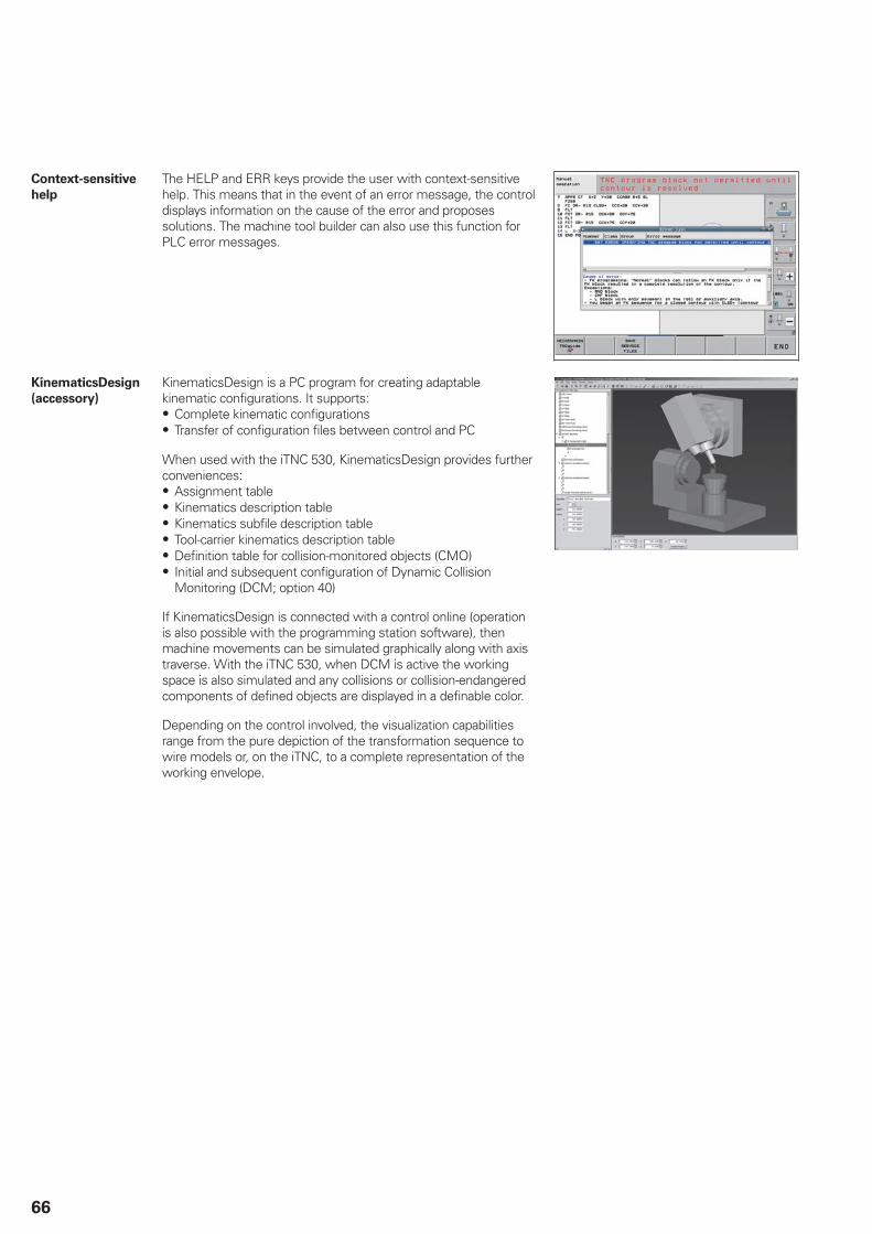
66
Context-sensitive
help
The HELP and ERR keys provide the user with context-sensitivehelp. This means that in the event of an error message, the controldisplays information on the cause of the error and proposessolutions. The machine tool builder can also use this function forPLC error messages.
KinematicsDesign
(accessory)
KinematicsDesign is a PC program for creating adaptablekinematic configurations. It supports:
Complete kinematic configurationsTransfer of configuration files between control and PC
When used with the iTNC 530, KinematicsDesign provides furtherconveniences:
Assignment tableKinematics description tableKinematics subfile description tableTool-carrier kinematics description tableDefinition table for collision-monitored objects (CMO)Initial and subsequent configuration of Dynamic CollisionMonitoring (DCM; option 40)
If KinematicsDesign is connected with a control online (operationis also possible with the programming station software), thenmachine movements can be simulated graphically along with axistraverse. With the iTNC 530, when DCM is active the workingspace is also simulated and any collisions or collision-endangeredcomponents of defined objects are displayed in a definable color.
Depending on the control involved, the visualization capabilitiesrange from the pure depiction of the transformation sequence towire models or, on the iTNC, to a complete representation of theworking envelope.
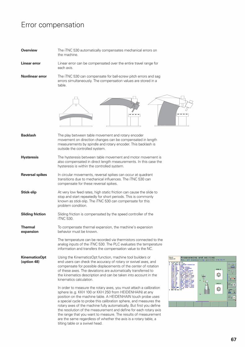
67
Error compensation
Overview The iTNC 530 automatically compensates mechanical errors onthe machine.
Linear error Linear error can be compensated over the entire travel range foreach axis.
Nonlinear error The iTNC 530 can compensate for ball-screw pitch errors and sagerrors simultaneously. The compensation values are stored in atable.
Backlash The play between table movement and rotary encodermovement on direction changes can be compensated in lengthmeasurements by spindle and rotary encoder. This backlash isoutside the controlled system.
Hysteresis The hysteresis between table movement and motor movement isalso compensated in direct length measurements. In this case thehysteresis is within the controlled system.
Reversal spikes In circular movements, reversal spikes can occur at quadranttransitions due to mechanical influences. The iTNC 530 cancompensate for these reversal spikes.
Stick-slip At very low feed rates, high static friction can cause the slide tostop and start repeatedly for short periods. This is commonlyknown as stick-slip. The iTNC 530 can compensate for thisproblem condition.
Sliding friction Sliding friction is compensated by the speed controller of theiTNC 530.
Thermal
expansion
To compensate thermal expansion, the machine’s expansionbehavior must be known.
The temperature can be recorded via thermistors connected to theanalog inputs of the iTNC 530. The PLC evaluates the temperatureinformation and transfers the compensation value to the NC.
KinematicsOpt
(option 48)
Using the KinematicsOpt function, machine tool builders orend users can check the accuracy of rotary or swivel axes, andcompensate for possible displacements of the center of rotationof these axes. The deviations are automatically transferred tothe kinematics description and can be taken into account in thekinematics calculation.
In order to measure the rotary axes, you must attach a calibrationsphere (e.g. KKH 100 or KKH 250 from HEIDENHAIN) at anyposition on the machine table. A HEIDENHAIN touch probe usesa special cycle to probe this calibration sphere, and measures therotary axes of the machine fully automatically. But first you definethe resolution of the measurement and define for each rotary axisthe range that you want to measure. The results of measurementare the same regardless of whether the axis is a rotary table, atilting table or a swivel head.

68
Calibration
sphere
(accessory)
HEIDENHAIN offers calibration spheres as accessories for the measurement of rotary axes with KinematicsOpt:
KKH 100 Height 100 mm ID 655475-02KKH 250 Height 250 mm ID 655475-01
KinematicsComp
(option 52)
Narrow workpiece tolerances require high machine accuracy.However, machine tools inevitably have errors resulting from theirassembly or the design.
The more axes a machine has, the more sources of errorsthere are. For example, according to ISO 230-1, a linear axis canhave six types of error, and a rotary axis can have eleven. Theuse of mechanical means to cope with these errors requiresconsiderable effort. These errors become particularly evident on 5-axis machines or very large machines. Thermal expansion that cancause highly complex geometry changes of machine componentscannot be disregarded either.
The KinematicsComp function (option 52) enables the machinetool builder to improve machine accuracy considerably.
The machine’s degrees of freedom and the positions of thecenters of rotation of the rotary axes are described in the standardkinematics of the iTNC 530. The expanded kinematics descriptionof KinematicsComp permits the import of compensation-value tables. Most of the geometry errors of a machine can bedescribed in compensation-value tables. They are compensatedin such a way that the tool center point follows exactly the idealnominal contour. Thermally induced errors are also measured andcompensated via sensors and the PLC.
For example, the spatial errors of the tool tip are measured with alaser tracer or laser interferometer.
The KinematicsComp option cannot be enabled for the exportversions.
Fault characteristics according to ISO 230-1: EBA
Fault characteristics according to ISO 230-1: EXA

69
Dynamic Precision The hypernym Dynamic Precision stands for a number ofHEIDENHAIN solutions for milling that dramatically improve thedynamic accuracy of a machine tool. The dynamic accuracy ofmachine tools can be seen in position errors at the Tool CenterPoint (TCP), which depend on the motion quantities such asvelocity and acceleration (also jerk) and result from vibrationsof machine components and other causes. All the deviationsare together responsible for dimensional errors and faults in theworkpiece surface. They therefore have a decisive influenceon quality and, when poor-quality parts are scrapped, also onproductivity.
Because the stiffness of machine tools is limited for reasons ofdesign and economy, problems such as compliance and vibrationwithin the machine design are very difficult to avoid. DynamicPrecision counteracts these problems with intelligent controltechnology to enable designers to further improve the qualityand dynamic performance of machine tools. That saves time andmoney in production.
The machine tool builder can use the options comprised byDynamic Precision either individually or in combination:
CTC – Compensates acceleration-dependent position errors atthe tool center point, thereby increasing accuracy in accelerationphasesAVD – Active vibration damping improves surfacesPAC – Position-dependent adaptation of control parametersLAC – Load-dependent adaptation of control parametersenhances accuracy regardless of load and agingMAC – Motion-dependent adaptation of control parameters
Cross Talk
Compensation
(CTC)
(option 141)
CTC (option 141) makes it possible to compensate dynamicposition deviations that can occur with the use of coupled axes.
To increase productivity, machine tool users are asking for everhigher feed rates and acceleration values, while at the same timethey need to maintain the highest possible surface quality andaccuracy, placing very special requirements on path control.
Highly dynamic acceleration processes introduce forces to thestructure of a machine tool. They can deform parts of the machineand thereby lead to deviations at the tool center point (TCP).Besides deformation in axis direction, the dynamic accelerationof an axis due to mechanical axis coupling can also result indeformation of axes that are perpendicular to the direction ofacceleration. The resulting position error at the TCP in the directionof the accelerated axis and lateral axes is proportional to theamount of acceleration.
If the dynamic position error as a function of the axis accelerationis known, this acceleration-dependent error can be compensatedwith the CTC option (Cross Talk Compensation) in order toprevent negative effects on the surface quality and accuracy ofthe workpiece. Often, the resulting error at the TCP depends notonly on the acceleration but also on the position of the axes inthe working space. This can also be compensated by the controloption CTC.

70
Active Vibration
Damping (AVD)
(option 146)
The high dynamics of modern machine tools lead to deformationsin the machine base, frame and drive train during acceleration anddeceleration of the feed drives. This results in vibrations, such asmachine setup vibrations, that may reduce the attainable accuracyand surface quality of the workpieces. The Active VibrationDamping (AVD) controller function dampens the especially criticallow-frequency oscillations and optimizes the control behaviorof the affected axis at the same time so that high-accuracyworkpieces with increased surface quality can also be producedat high feed rates. The improved rigidity attained can be used toincrease the dynamic limit values (e.g. jerk), and therefore makesreduced machining times possible.
Position Adaptive
Control (PAC)
(option 142)
Option 142, PAC, permits dynamic and position-dependentadaptation of controller parameters depending on the position ofthe tool in space.
The specifics of a machine’s kinematics cause a unique positionof the axes’ center of gravity in the working space. This results ina variable dynamic behavior of the machine, which can negativelyinfluence the control’s stability depending on the axis positions.
To exploit the machine’s dynamic possibilities, you can usethe PAC option (Position Adaptive Control) to change machineparameters depending on position. This makes it possible toassign the respectively optimal loop gain to defined supportpoints. Additional position-dependent filter parameters can bedefined in order to further increase control loop stability.
Load Adaptive
Control (LAC )
(option 143)
LAC (option 143) enables you to adapt controller parametersdynamically depending on the load or friction.
The dynamic behavior of machines with rotary tables can varydepending on the mass moment of inertia of the fixed workpiece.The LAC option (Load Adaptive Control) enables the control toautomatically ascertain the workpiece’s current mass moment ofinertia and the friction forces.
In order to optimize changed control behavior at differing loads,adaptive feedforward controls can exploit data on acceleration,holding torque, static friction and friction at high shaft speeds.
71
Motion Adaptive
Control (MAC)
(option 144)
In addition to the position-dependent adjustment of machineparameters by the PAC option, the MAC option (Motion AdaptiveControl) also provides a way to change machine parameter valuesdepending on other input quantities such as velocity, followingerror or acceleration of a drive. Through this motion-dependentadaptation of the control parameters it is possible, for example,to realize a velocity-dependent adaptation of the control loop gainon motors whose stability changes through the various traversingvelocities.
Crossover Position
Filter (CPF)
To increase the stability of the position control loop in systemswith resonances, the position signal from the position encoder,which is filtered through a low-pass filter, is combined with theposition signal from the motor speed encoder, which is filteredthrough a high-pass filter. This signal combination is made availableto the position controller as actual position value. This results ina significant increase in the possible position controller gain (kV
factor). The filter separation frequency is set specifically for eachaxis via machine parameters. The CPF can be used only in dual-encoder systems, i.e. on drive motors with speed encoder andposition encoder.
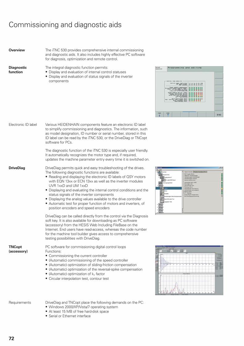
72
Commissioning and diagnostic aids
Overview The iTNC 530 provides comprehensive internal commissioningand diagnostic aids. It also includes highly effective PC softwarefor diagnosis, optimization and remote control.
Diagnostic
function
The integral diagnostic function permits:Display and evaluation of internal control statusesDisplay and evaluation of status signals of the invertercomponents
Electronic ID label Various HEIDENHAIN components feature an electronic ID labelto simplify commissioning and diagnostics. The information, suchas model designation, ID number or serial number, stored in thisID label can be read by the iTNC 530, or the DriveDiag or TNCoptsoftware for PCs.
The diagnostic function of the iTNC 530 is especially user friendly.It automatically recognizes the motor type and, if required,updates the machine parameter entry every time it is switched on.
DriveDiag DriveDiag permits quick and easy troubleshooting of the drives.The following diagnostic functions are available:
Reading and displaying the electronic ID labels of QSY motorswith EQN 13xx or ECN 13xx as well as the inverter modulesUVR 1xxD and UM 1xxDDisplaying and evaluating the internal control conditions and thestatus signals of the inverter componentsDisplaying the analog values available to the drive controllerAutomatic test for proper function of motors and inverters, ofposition encoders and speed encoders
DriveDiag can be called directly from the control via the Diagnosissoft key. It is also available for downloading as PC software(accessory) from the HESIS Web Including FileBase on theInternet. End users have read-access, whereas the code numberfor the machine tool builder gives access to comprehensivetesting possibilities with DriveDiag.
TNCopt
(accessory)
PC software for commissioning digital control loopsFunctions:
Commissioning the current controller(Automatic) commissioning of the speed controller(Automatic) optimization of sliding-friction compensation(Automatic) optimization of the reversal-spike compensation(Automatic) optimization of kV factorCircular interpolation test, contour test
Requirements DriveDiag and TNCopt place the following demands on the PC:Windows 2000/XP/Vista/7 operating systemAt least 15 MB of free hard-disk spaceSerial or Ethernet interface
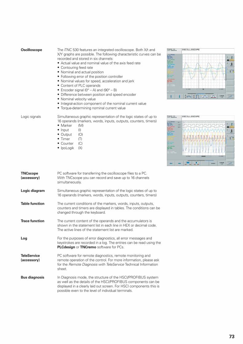
73
Oscilloscope The iTNC 530 features an integrated oscilloscope. Both X/t andX/Y graphs are possible. The following characteristic curves can berecorded and stored in six channels:
Actual value and nominal value of the axis feed rateContouring feed rateNominal and actual positionFollowing error of the position controllerNominal values for speed, acceleration and jerkContent of PLC operandsEncoder signal (0° – A) and (90° – B)Difference between position and speed encoderNominal velocity valueIntegral-action component of the nominal current valueTorque-determining nominal current value
Logic signals Simultaneous graphic representation of the logic states of up to16 operands (markers, words, inputs, outputs, counters, timers)
Marker (M)Input (I)Output (O)Timer (T)Counter (C)IpoLogik (X)
TNCscope
(accessory)
PC software for transferring the oscilloscope files to a PC. With TNCscope you can record and save up to 16 channelssimultaneously.
Logic diagram Simultaneous graphic representation of the logic states of up to16 operands (markers, words, inputs, outputs, counters, timers)
Table function The current conditions of the markers, words, inputs, outputs,counters and timers are displayed in tables. The conditions can bechanged through the keyboard.
Trace function The current content of the operands and the accumulators isshown in the statement list in each line in HEX or decimal code.The active lines of the statement list are marked.
Log For the purposes of error diagnostics, all error messages andkeystrokes are recorded in a log. The entries can be read using thePLCdesign or TNCremo software for PCs.
TeleService
(accessory)
PC software for remote diagnostics, remote monitoring andremote operation of the control. For more information, please askfor the Remote Diagnosis with TeleService Technical Informationsheet.
Bus diagnosis In Diagnosis mode, the structure of the HSCI/PROFIBUS systemas well as the details of the HSCI/PROFIBUS components can bedisplayed in a clearly laid out screen. For HSCI components this ispossible even to the level of individual terminals.
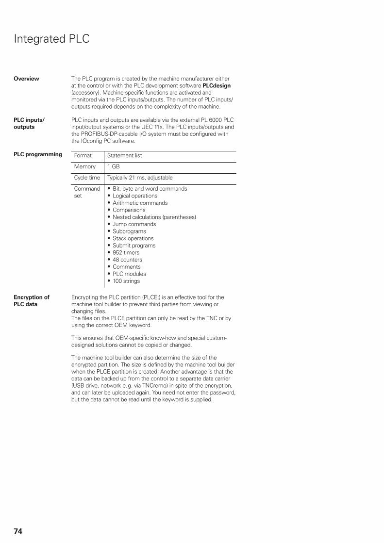
74
Integrated PLC
Overview The PLC program is created by the machine manufacturer eitherat the control or with the PLC development software PLCdesign
(accessory). Machine-specific functions are activated andmonitored via the PLC inputs/outputs. The number of PLC inputs/outputs required depends on the complexity of the machine.
PLC inputs/
outputs
PLC inputs and outputs are available via the external PL 6000 PLCinput/output systems or the UEC 11x. The PLC inputs/outputs andthe PROFIBUS-DP-capable I/O system must be configured withthe IOconfig PC software.
PLC programming Format Statement list
Memory 1 GB
Cycle time Typically 21 ms, adjustable
Commandset
Bit, byte and word commandsLogical operationsArithmetic commandsComparisonsNested calculations (parentheses)Jump commandsSubprogramsStack operationsSubmit programs952 timers48 countersCommentsPLC modules100 strings
Encryption of
PLC data
Encrypting the PLC partition (PLCE:) is an effective tool for themachine tool builder to prevent third parties from viewing orchanging files. The files on the PLCE partition can only be read by the TNC or byusing the correct OEM keyword.
This ensures that OEM-specific know-how and special custom-designed solutions cannot be copied or changed.
The machine tool builder can also determine the size of theencrypted partition. The size is defined by the machine tool builderwhen the PLCE partition is created. Another advantage is that thedata can be backed up from the control to a separate data carrier(USB drive, network e.g. via TNCremo) in spite of the encryption,and can later be uploaded again. You need not enter the password,but the data cannot be read until the keyword is supplied.

75
PLC window PLC error messages can be displayed by the TNC in the dialog lineduring operation.
Small PLC window The TNC can show additional PLC messages and bar diagrams inthe small PLC window.
Small PLC window
Large PLC window A complete PLC page can be shown as a window. PLC messagesand graphics can be displayed.
PLC soft keys With the BF 750, the machine tool builder can define his ownsoft keys on the screen, instead of the horizontal NC soft keys. Inaddition, he can define his own PLC soft keys in the vertical soft-key row. The BF 760 also features soft keys on the left of the screen. Self-defined soft keys can be shown there as required.
PLC positioning All closed-loop axes can be also positionedvia the PLC. PLC positioning of the NCaxes cannot be superimposed on NCpositioning.
PLC axes Axes can be controlled by the PLC. They are programmedby M functions or OEM cycles. The PLC axes are positionedindependently of the NC axes.

76
PLCdesign
(accessory)
PC software for PLC program development. The PC program PLCdesign can be used for easy creation ofPLC programs. Comprehensive examples of PLC programs areincluded with the product.
Functions:Easy-to-use text editorMenu-guided operationProgramming of symbolic operandsModular programming method“Compiling” and “linking” of PLC source filesOperand commenting, creation of the documentation fileComprehensive help systemData transfer between the PC and controlCreation of PLC soft keys
PC requirements:Windows 2000/XP/Vista/7 operating systemAt least 20 MB free memory on the hard diskSerial interface; Ethernet interface recommendedInternet Explorer
Python OEM
Process
(option 46)
The Python OEM Process option is an effective tool for themachine tool builder to use an object-oriented high-levelprogramming language in the control (PLC). Python is an easy-to-learn script language that supports the use of all necessary high-level language elements.
Python OEM Process can be universally used for machinefunctions and complex calculations, as well as to display specialuser interfaces. User-specific or machine-specific solutions can beefficiently implemented. Numerous libraries on the basis of Pythonand GTK are available, regardless of whether you want to createspecial algorithms for special functions, or separate solutions suchas an interface for machine maintenance software.
The applications created can be included via the PLC in the familiarPLC windows, or they can be displayed in separate free windowsthat can be expanded to the control’s full screen size.

77
PLC basic
program
The PLC basic program serves as a basis for adapting thecontrol to the requirements of the respective machine. It can bedownloaded from the Internet.
These essential functions are covered by the PLC basic program:Controlling all axesClamped axesHoming the axes; reference end positionsPositioning the axes after reference runCompensating the axis temperatureSwitching the traverse rangesAlternating table operationFeed rate controlControlling and orienting the spindleActivating tool-specific torque monitoringTool changerPallet changer (translational, rotatory, setup functions)Vertical PLC soft-key rowSupport for 19” screensDisplaying and managing PLC error messagesStatus display in the small PLC windowHydraulic controlControl of the coolant system (internal, external, air)M functionsLubricationChip conveyorOperation of the second spindle alternately with the firstWye/delta connection switchover (static, dynamic)S-coded spindle3-D head with C-axis operation3-D head changePositioning the spindle as an axisOperation with clamped axesAxes with central driveAxes with Hirth gridIndexing fixturePLC logTouch probesPLC support for handwheelsControl of doorsSupport for IPC 61xx
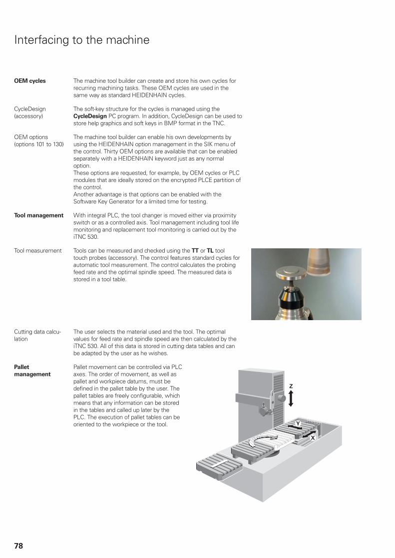
78
Interfacing to the machine
OEM cycles The machine tool builder can create and store his own cycles forrecurring machining tasks. These OEM cycles are used in thesame way as standard HEIDENHAIN cycles.
CycleDesign (accessory)
The soft-key structure for the cycles is managed using theCycleDesign PC program. In addition, CycleDesign can be used tostore help graphics and soft keys in BMP format in the TNC.
OEM options(options 101 to 130)
The machine tool builder can enable his own developments byusing the HEIDENHAIN option management in the SIK menu ofthe control. Thirty OEM options are available that can be enabledseparately with a HEIDENHAIN keyword just as any normaloption. These options are requested, for example, by OEM cycles or PLCmodules that are ideally stored on the encrypted PLCE partition ofthe control.Another advantage is that options can be enabled with theSoftware Key Generator for a limited time for testing.
Tool management With integral PLC, the tool changer is moved either via proximityswitch or as a controlled axis. Tool management including tool lifemonitoring and replacement tool monitoring is carried out by theiTNC 530.
Tool measurement Tools can be measured and checked using the TT or TL tooltouch probes (accessory). The control features standard cycles forautomatic tool measurement. The control calculates the probingfeed rate and the optimal spindle speed. The measured data isstored in a tool table.
Cutting data calcu-lation
The user selects the material used and the tool. The optimalvalues for feed rate and spindle speed are then calculated by theiTNC 530. All of this data is stored in cutting data tables and canbe adapted by the user as he wishes.
Pallet
management
Pallet movement can be controlled via PLCaxes. The order of movement, as well aspallet and workpiece datums, must bedefined in the pallet table by the user. Thepallet tables are freely configurable, whichmeans that any information can be storedin the tables and called up later by thePLC. The execution of pallet tables can beoriented to the workpiece or the tool.

79
Data transfer and communication
Data interfaces
Overview The iTNC 530 is connected to PCs, networks and other datastorage devices via data interfaces.
Ethernet The iTNC 530 can be interconnected via the Ethernet interface.The control features a 1000BASE-T (Twisted Pair Ethernet)connection to the data network.
Maximum transmission distance: Unshielded 100 m Shielded 400 m
Protocol The iTNC 530 communicates using the TCP/IP protocol.
Network connec-tion
NFS file serverWindows networks (SMB)
Data transfer rate Approx. 400 to 800 Mbit/s (depending on file type and networkutilization)
RS-232-C/V.24 Data interface according to DIN 66 020 or EIA standard RS-232-C.Maximum transmission distance: 20 m
Data transfer rate 115 200; 57 600; 38 400; 19 200; 9600; 4800; 2400; 1200; 600;300; 150; 110 Bit/s
Protocols The iTNC 530 can transfer data using various protocols.
Standard datatransfer
The data is transferred character by character. The number of databits, stop bits, the handshake and character parity must be set bythe user.
Blockwise datatransfer
The data is transferred blockwise. A block check character (BCC) isused to ensure data integrity. This method improves data security.
LSV2 Bidirectional transfer of commands and data as per DIN 66 019.Before being transferred the data are split into telegrams (blocks).
Adapter block For connecting the interface to the electrical cabinet or operatingpanel
9-pin ID 363987-02RS-232-C/V.24 adapter
25-pin ID 310085-01
USB The MC 7xxx features two USB 3.0 ports for the connectionof standard USB devices, such as the mouse, drives, etc. Oneof them is led to the BF or TE. There the user has an easilyaccessible USB interface. The integrated USB hub on the rear ofthe screen has further USB ports. The USB ports are rated for amaximum of 0.5 A.
USB cable Cable length up to 5 m ID 354770-xxCable length 6 m to 30 m with integratedamplifier; USB 1.1.
ID 624775-xx

80
USB hub If you need further USB ports or if the supply current is notsufficient, a USB hub is required. The USB hub from HEIDENHAINoffers four free USB ports.
USB hub ID 582884-02Power supply 24 V DC / max. 300 mA
Cover The USB hub can be installed in the operating panel in such away that two USB ports can be accessed from the outside. Anoptionally available cover cap can be used to protect the portsfrom contamination.
Cover ID 508921-01
Software for data
transfer
To transfer files between the iTNC 530 and PC, we recommendusing HEIDENHAIN software.
TNCremo
(accessory)
This PC software package helps the user to transfer data fromthe PC to the control. The software transfers data blockwise withblock check characters (BCC).
Functions:Data transfer (also blockwise)Remote control (only serial)File management and data backup of the controlReading out the logPrint-out of screen contentsText editorManaging more than one machine
Requirements:Windows 2000/XP/Vista/7 operating systemAt least 10 MB free hard-disk spaceSerial or Ethernet interface
TNCremoPlus
(accessory)
In addition to the features you are already familiar with fromTNCremo, TNCremoPlus can also transfer the current contentof the control’s screen to the PC (live screen). This makes it verysimple to monitor the machine.
TNCremoPlus ID 340447-xx
Remote Desktop
Manager
(option 133)
Remote operation and display of external computer units viaEthernet connection (e.g. to a Windows PC). The information isdisplayed on the control’s screen.
Remote desktop manager ID 894423-01
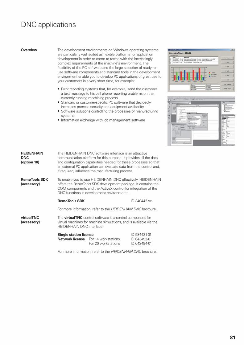
81
DNC applications
Overview The development environments on Windows operating systemsare particularly well suited as flexible platforms for applicationdevelopment in order to come to terms with the increasinglycomplex requirements of the machine’s environment. Theflexibility of the PC software and the large selection of ready-to-use software components and standard tools in the developmentenvironment enable you to develop PC applications of great use toyour customers in a very short time, for example:
Error reporting systems that, for example, send the customera text message to his cell phone reporting problems on thecurrently running machining processStandard or customer-specific PC software that decidedlyincreases process security and equipment availabilitySoftware solutions controlling the processes of manufacturingsystemsInformation exchange with job management software
HEIDENHAIN
DNC
(option 18)
The HEIDENHAIN DNC software interface is an attractivecommunication platform for this purpose. It provides all the dataand configuration capabilities needed for these processes so thatan external PC application can evaluate data from the control and,if required, influence the manufacturing process.
RemoTools SDK
(accessory)
To enable you to use HEIDENHAIN DNC effectively, HEIDENHAINoffers the RemoTools SDK development package. It contains theCOM components and the ActiveX control for integration of theDNC functions in development environments.
RemoTools SDK ID 340442-xx
For more information, refer to the HEIDENHAIN DNC brochure.
virtualTNC
(accessory)
The virtualTNC control software is a control component forvirtual machines for machine simulations, and is available via theHEIDENHAIN DNC interface.
Single station license ID 584421-01For 14 workstations ID 643492-01Network license
For 20 workstations ID 643494-01
For more information, refer to the HEIDENHAIN DNC brochure.
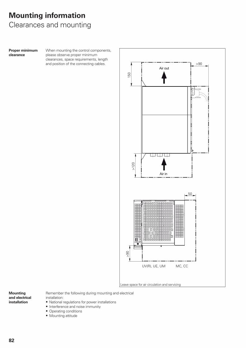
82
Mounting information
Clearances and mounting
Proper minimum
clearance
When mounting the control components,please observe proper minimumclearances, space requirements, lengthand position of the connecting cables.
Leave space for air circulation and servicing
Mounting
and electrical
installation
Remember the following during mounting and electricalinstallation:
National regulations for power installationsInterference and noise immunityOperating conditionsMounting attitude

83
Degrees of
protection
The following components fulfill the requirements for IP 54 (dustprotection and splash-proof protection):
Visual display unit (when properly installed)Keyboard unit (when properly installed)Machine operating panel (when properly installed)Handwheel
All electric and electronic control components must be installedin an environment (e.g. electrical cabinet, housing) that fulfillsthe requirements of protection class IP 54 (dust and splash-proofprotection) in order to fulfill the requirements of contaminationlevel 2. All components of the OEM operating panel must alsocomply with protection class IP 54, just like the HEIDENHAINoperating panel components.
Electromagnetic
compatibility
Protect your equipment from interference by observing the rulesand recommendations specified in the Technical Manual.
Intended place ofoperation
This unit fulfills the requirements for EN 50370-1 and is intendedfor operation in industrially zoned areas.
Likely sources ofinterference
Interference is produced by capacitive and inductive coupling intoelectrical conductors or into device connections, caused by e.g.:
Strong magnetic fields from transformers or electric motorsRelays, contactors and solenoid valvesHigh-frequency equipment, pulse equipment and stray magneticfields from switch-mode power suppliesPower lines and leads to the above equipment
Protective mea-sures
Keep a minimum distance of 20 cm from the MC, CC and itsleads to devices that carry interference signalsKeep a minimum distance of 10 cm from the MC, CC and itsleads to cables that carry interference signals. For cables inmetallic ducting, adequate decoupling can be achieved by usinga grounded separation shield.Shielding according to EN 50 178Use equipotential bonding conductors with a cross section of6 mm2
Use only genuine HEIDENHAIN cables and connectingelements

84
Overall dimensions
Main computer
MC 6441, MC 6541, MC 6641, IPC 6641

85
MC 6542
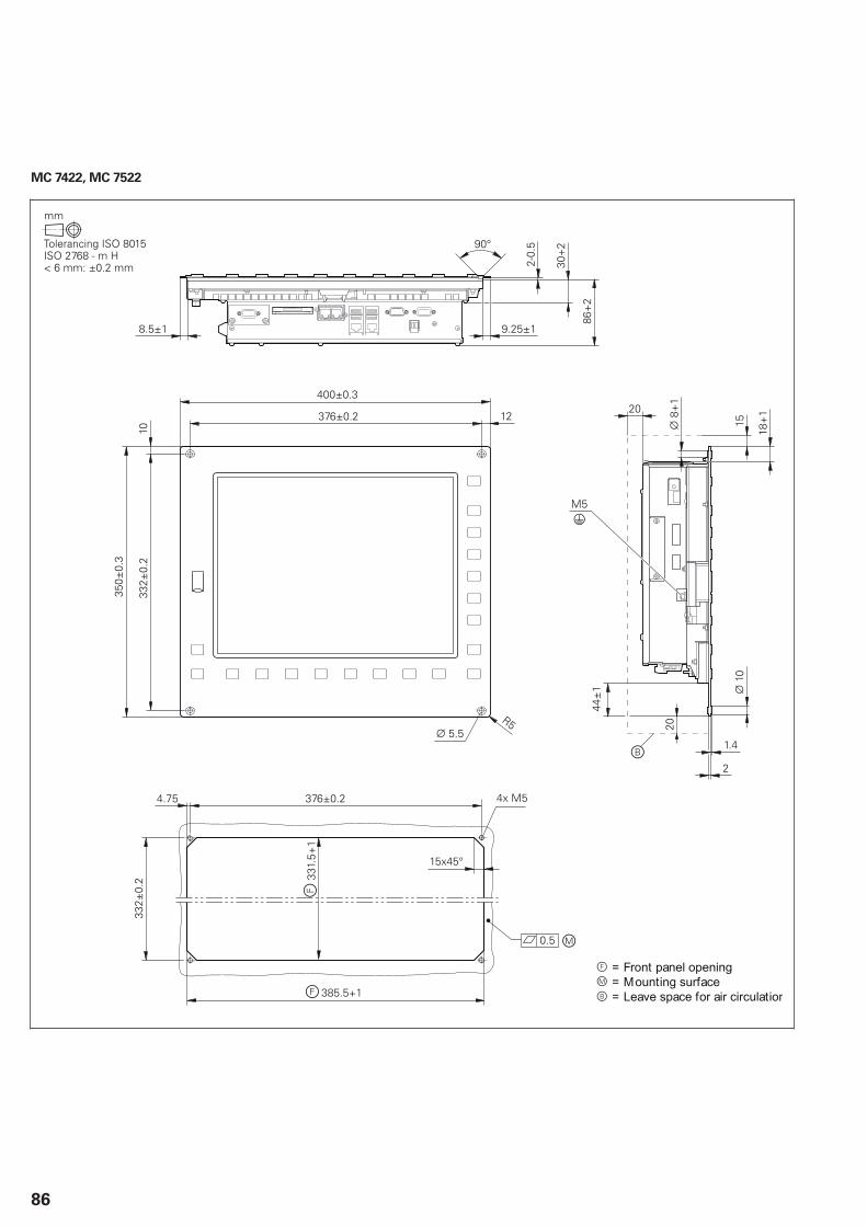
86
MC 7422, MC 7522

87
Controller unit
CC 6106
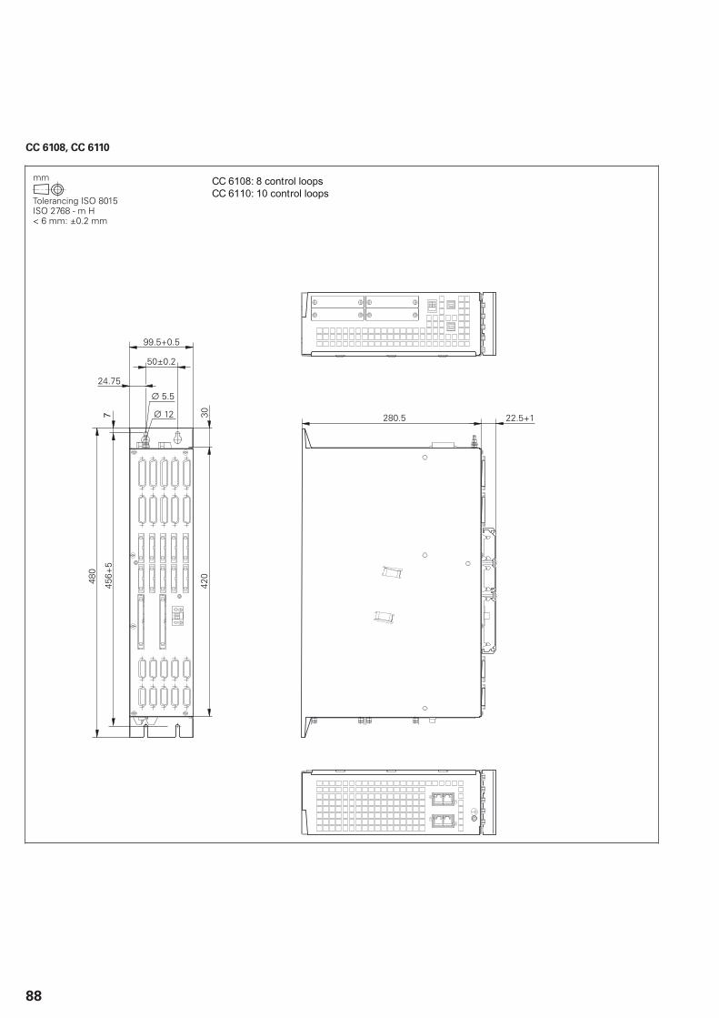
88
CC 6108, CC 6110
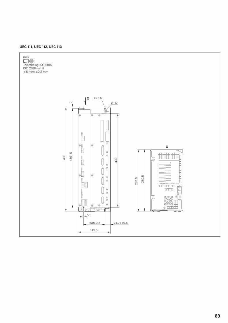
89
UEC 111, UEC 112, UEC 113
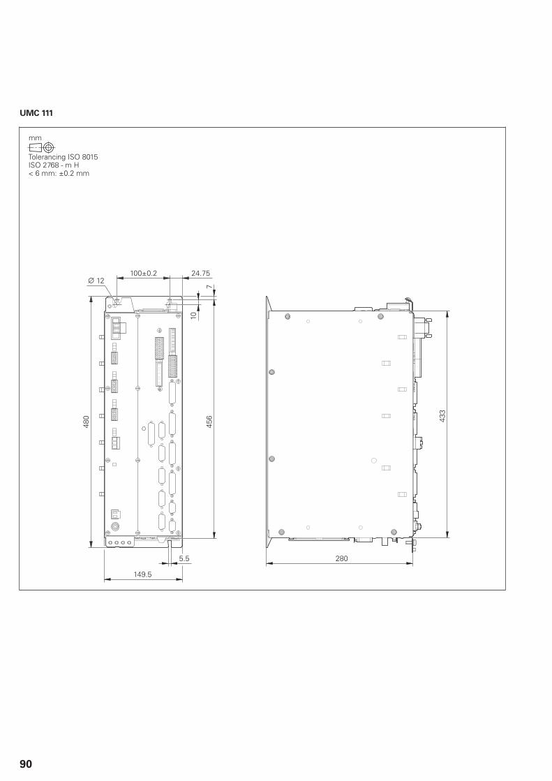
90
UMC 111

91
Monitor and keyboards
BF 760
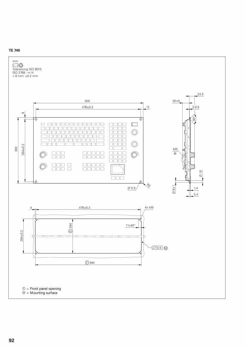
92
TE 740
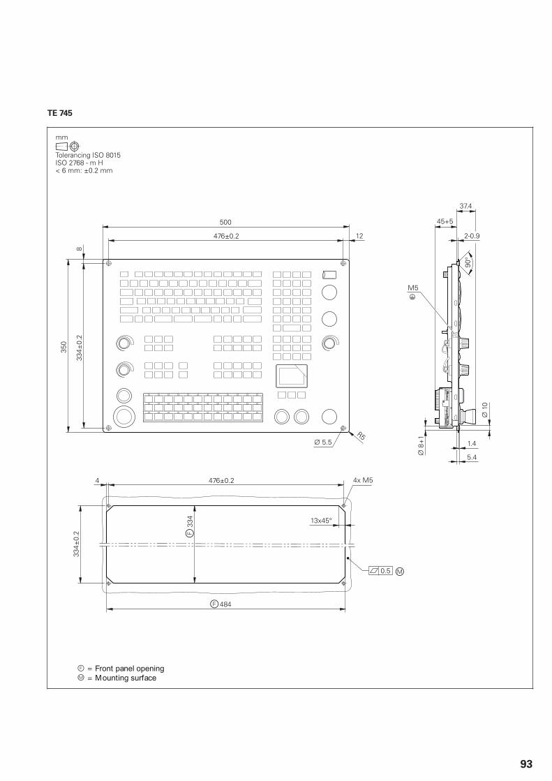
93
TE 745
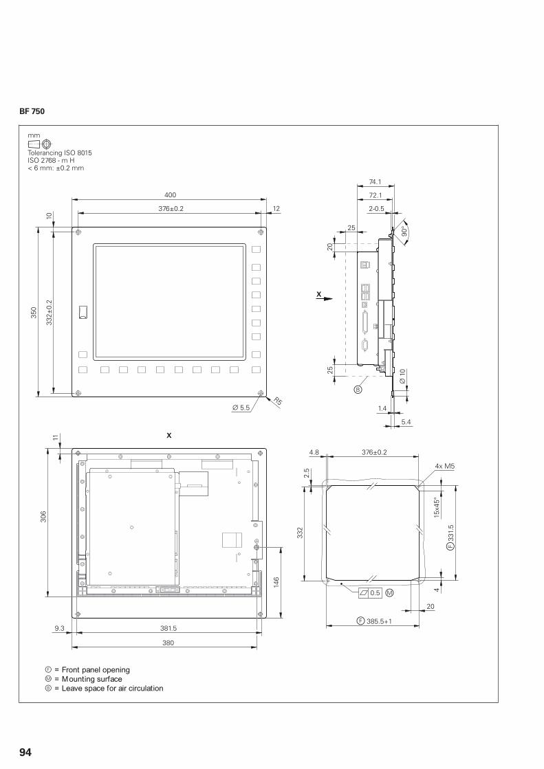
94
BF 750
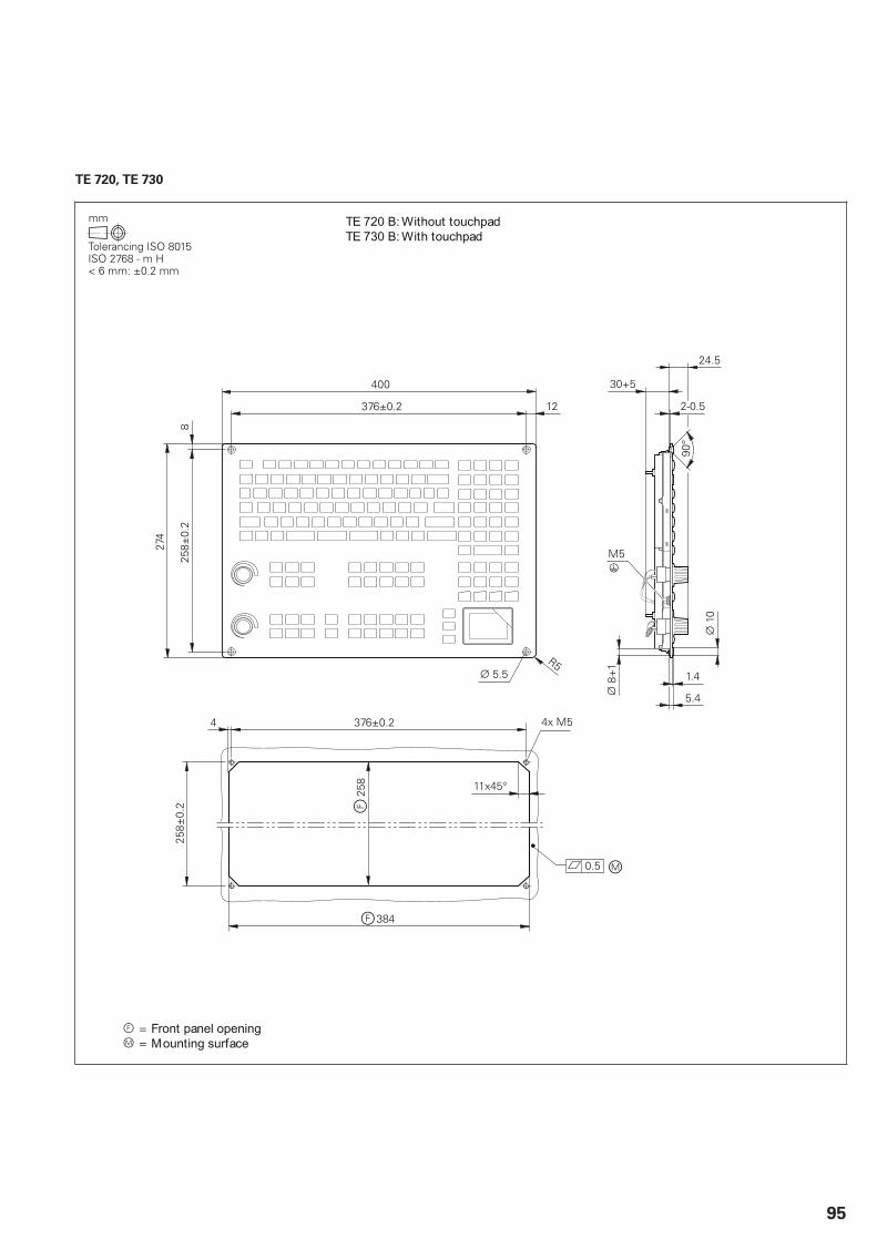
95
TE 720, TE 730
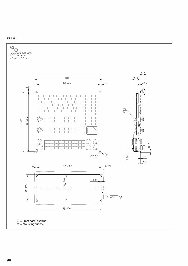
96
TE 735
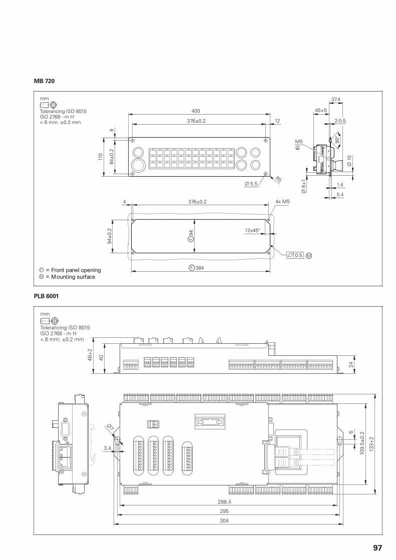
97
MB 720
PLB 6001

98
PLC inputs and outputs
PL 6000 (PLB 62xx, PLB 61xx)
PL 550

99
Power supply units
PSL 130
PSL 135
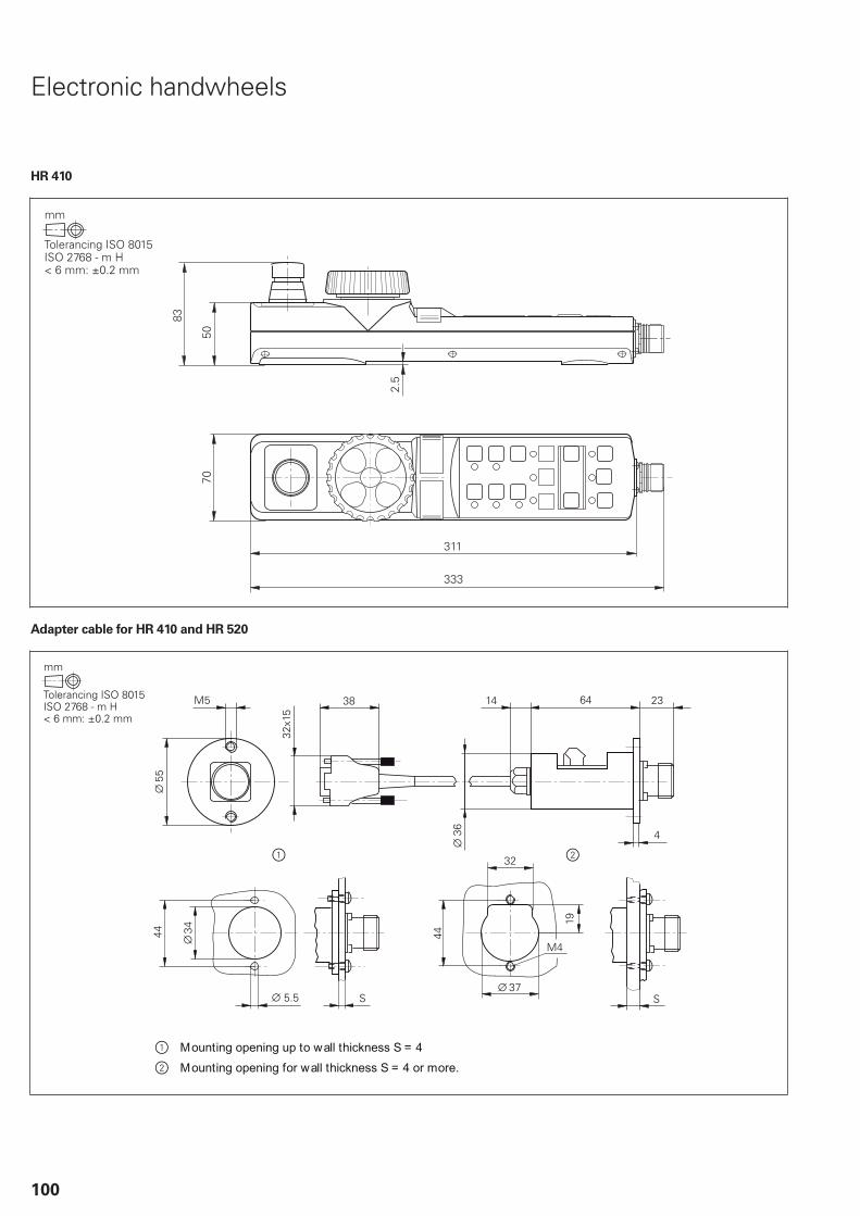
100
Electronic handwheels
HR 410
Adapter cable for HR 410 and HR 520

101
HR 520
Mount for HR 520

102
HR 550 FS
HRA 551 FS
Tolerancing ISO 8015ISO 2768 - m H< 6 mm: ±0.2 mm
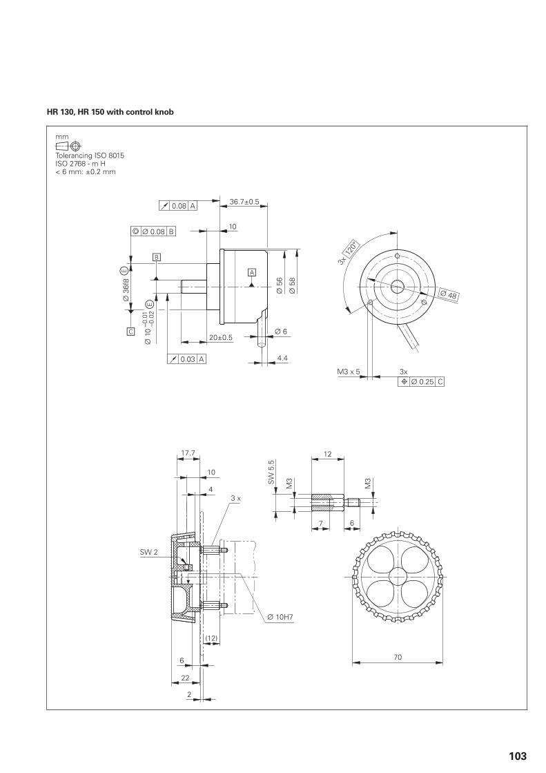
103
HR 130, HR 150 with control knob
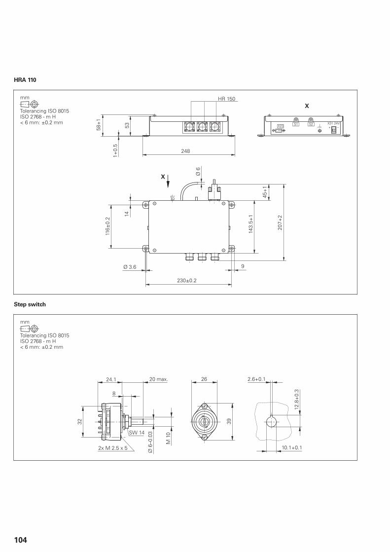
104
HRA 110
Step switch
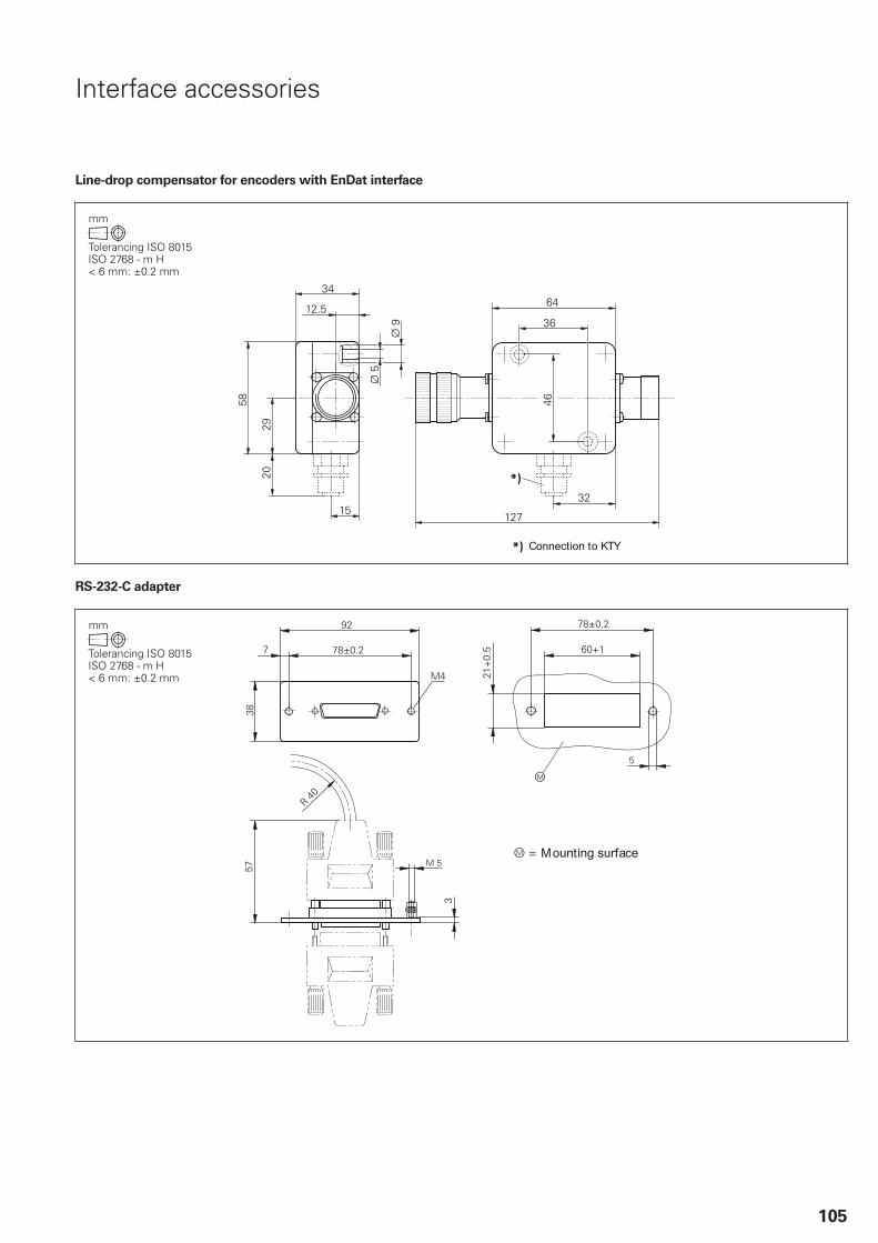
105
Interface accessories
Line-drop compensator for encoders with EnDat interface
RS-232-C adapter
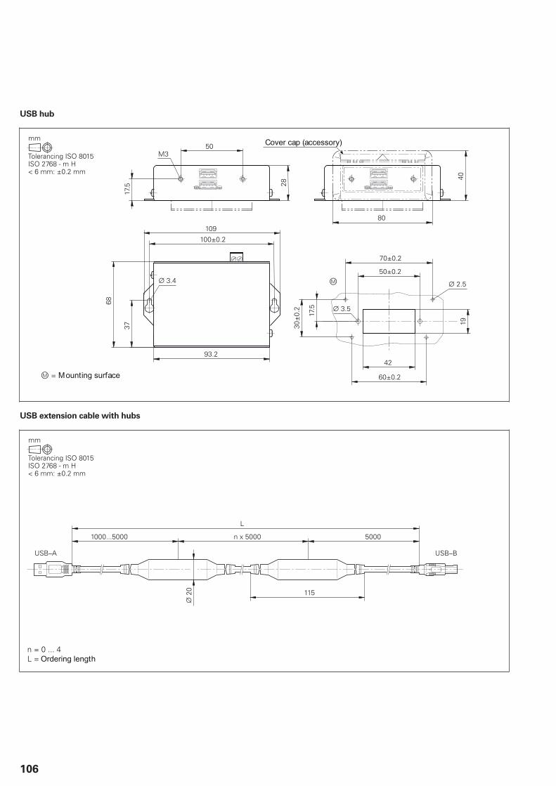
106
USB hub
USB extension cable with hubs

107
General information
Documentation
Technical
documentation
iTNC 530 HSCI Technical Manual ID 801739-xx; in PDF format on HESIS-Webincluding Filebase
Inverter Systems and Motors Technical Manual ID 208962-xxFunctional Safety Technical Manual ID 749363-xxTS 230 Mounting Instructions ID 312821-91TS 440 Mounting Instructions ID 632756-9xTS 444 Mounting Instructions ID 632757-9xTS 640 Mounting Instructions ID 632760-9xTS 740 Mounting Instructions ID 632761-9xTT 140 Mounting Instructions ID 297510-xxTT 449 Mounting Instructions ID 664914-xx
User
documentation
iTNC 530 For NC software 34049x-xx
Conversational Programming User’s Manual ID 670387-xxCycle Programming User’s Manual ID 670388-xxDIN/ISO User’s Manual ID 670391-xxsmarT.NC Pilot ID 533191-xx
Miscellaneous
TNCremo User’s Manual As integrated helpTNCremoPlus User’s Manual As integrated helpPLCdesign User’s Manual As integrated helpCycleDesign User’s Manual As integrated helpIOconfig User’s Manual As integrated helpKinematicsDesign User’s Manual As integrated help
Other
documentation
iTNC 530 brochure ID 892921-xxTouch Probes brochure ID 208951-xx
• Inverter Systems brochure ID 622420-xxMotors brochure ID 208893-xxIPC Product Information ID 630601-xxHEIDENHAIN DNC brochure ID 628968-xxRemote Diagnosis with TeleService Product Overview ID 348236-xxTouch Probes CD-ROM ID 344353-xxiTNC 530 Presentation CD-ROM ID 373080-xxiTNC Programming Station Demo Version CD-ROM ID 384565-xxHR 550FS Product Information PDFTechnical Information:Safety-Related Control Technology
Technical Information:Safety-Related Position Measuring Systems
Technical Information:Uniformly Digital
108
Service and training
Technical support HEIDENHAIN offers the machine manufacturer technical supportto optimize the adaptation of the TNC to the machine, includingon-site support.
Replacement
control system
In the event of a fault, HEIDENHAIN guarantees the rapid supplyof a replacement control system (usually within 24 hours inEurope).
Hotline Our service engineers are naturally at your disposal by telephoneif you have any questions on the interfacing of the control or in theevent of faults.
TNC support +49 8669 31-3101 E-mail: [email protected]
PLC programming +49 8669 31-3102E-mail: [email protected]
NC programming +49 8669 31-3103 E-mail: [email protected]
Measuring systems +49 8669 31-3104 E-mail: [email protected]
Lathe controls +49 8669 31-3105 E-mail: [email protected]
Machine
calibration
On request, HEIDENHAIN engineers will calibrate your machine’sgeometry, e.g. with a KGM grid encoder.
Seminars HEIDENHAIN provides technical customer training in the followingsubjects:
NC programmingPLC programmingTNC optimizationTNC serviceEncoder serviceSpecial training for specific customers
For more information on dates, registration, etc. call in Germany:+49 8669 31-2293 or 31-1695+49 8669 31-1999E-mail: [email protected]
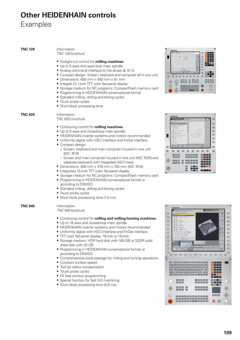
109
Other HEIDENHAIN controls
Examples
TNC 128 Information: TNC 128 brochure
Straight-cut control for milling machines
Up to 5 axes and open-loop main spindleAnalog command interface to the drives ( 10 V)Compact design: Screen, keyboard and computer all in one unitDimensions: 400 mm x 450 mm x 91 mmIntegral 12.1-inch TFT color flat-panel displayStorage medium for NC programs: CompactFlash memory cardProgramming in HEIDENHAIN conversational formatStandard milling, drilling and boring cyclesTouch probe cyclesShort block processing time
TNC 620 Information: TNC 620 brochure
Contouring control for milling machines
Up to 5 axes and closed-loop main spindleHEIDENHAIN inverter systems and motors recommendedUniformly digital with HSCI interface and EnDat interfaceCompact design:– Screen, keyboard and main computer housed in one unit
(MC 7410)– Screen and main computer housed in one unit (MC 7420) and
separate keyboard with integrated ASCII keysDimensions: 400 mm x 470 mm x 100 mm (MC 7410)Integrated 15-inch TFT color flat-panel displayStorage medium for NC programs: CompactFlash memory cardProgramming in HEIDENHAIN conversational format oraccording to DIN/ISOStandard milling, drilling and boring cyclesTouch probe cyclesShort block processing time (1.5 ms)
TNC 640 Information: TNC 640 brochure
Contouring control for milling and milling/turning machines
Up to 18 axes and closed-loop main spindleHEIDENHAIN inverter systems and motors recommendedUniformly digital with HSCI interface and EnDat interfaceTFT color flat-panel display, 19-inch or 15-inchStorage medium: HDR hard disk with 160 GB or SSDR solidstate disk with 32 GBProgramming in HEIDENHAIN conversational format oraccording to DIN/ISOComprehensive cycle package for milling and turning operationsConstant surface speedTool-tip radius compensationTouch probe cyclesFK free contour programmingSpecial function for fast 3-D machiningShort block processing time (0.5 ms)
110
Subject index
5
5-axis machining.................................. 57
A
Absolute encoders.............................. 60Accessories..................................... 5, 51Active Chatter Control......................... 64Active Vibration Damping..................... 70Adaptive Feed Control (AFC)................ 64Additional modules.............................. 34Axes................................................... 56Axis clamping...................................... 62Axis feedback control.......................... 61
B
Backlash.............................................. 67Basic modules..................................... 29BF 750.......................................... 27, 94BF 760.......................................... 28, 91Bus diagnosis...................................... 73
C
Cable overview................................... 45Calibration sphere................................ 68CC 6106........................................ 22, 87CC 6108.............................................. 22CC 6108, CC 6110............................... 88CC 6110.............................................. 22CC 61xx.............................................. 22CMA-H 02-00-04................................. 34CMA-H 04-04-00................................. 34CMD-H 24-12-00................................. 34Commissioning and diagnostic aids...... 72Compensation of torque ripples........... 61Components......................................... 4Connecting cable................................. 39Context-sensitive help......................... 66Controller unit..................................... 21Control loop cycle times...................... 62Crossover Position Filter (CPF)............. 71Cross Talk Compensation (CTC)........... 69Cycle times......................................... 21Cylindrical surface interpolation............ 56
D
Data interfaces.................................... 79Degrees of protection......................... 83Diagnostic function.............................. 72Digital control design........................... 52Digital servo control............................ 61Display step.......................................... 6DNC applications................................. 81Double speed...................................... 21Double-speed control loops................. 62DriveDiag............................................ 72Dynamic Collision Monitoring.............. 65Dynamic Efficiency.............................. 63
Dynamic Precision............................... 69
E
Electromagnetic compatibility.............. 83Electronic handwheels........................ 38Empty housing.............................. 30, 31Encoder inputs.................................... 60Encryption of PLC data........................ 74EnDat 2.2............................................ 52Error compensation............................. 67Ethernet.............................................. 79Expansion PL...................................... 29Export version..................................... 15
F
Fast contour milling............................. 63Feature Content Level (FCL)................ 18Flat-panel display................................. 27Functional safety................................. 53
G
Gantry axes......................................... 57Gear ranges........................................ 59
H
HEROS 5............................................ 55HR 130....................................... 40, 103HR 150....................................... 40, 103HR 410....................................... 38, 100HR 410 FS.......................................... 38HR 520....................................... 38, 101HR 520 FS.......................................... 38HR 550 FS.................................. 39, 102HRA 110...................................... 40, 104HRA 551 FS................................ 39, 102HSCI................................................... 52HSCI adapter....................................... 33HSCI control components.................... 15Hysteresis........................................... 67
I
I/O modules.................................. 30, 31Incremental encoders.......................... 60Industrial PC........................................ 41Input resolution..................................... 6Integrated inverter............................... 61Integrated PLC.................................... 74Inverter system................................... 50IOconfig........................................ 30, 31IPC 6110............................................. 41IPC 6120............................................. 41IPC 6641....................................... 41, 84
J
Jerk..................................................... 62Jerk limiting........................................ 62
Jerk smoothing................................... 62
K
KinematicsComp................................. 68KinematicsDesign................................ 66
L
Linear axes.......................................... 56Linear error......................................... 67Load Adaptive Control (LAC)................ 70Log..................................................... 73Logic diagram...................................... 73Look-ahead.......................................... 63
M
Machine interfacing............................... 8Machine operating panel..................... 27Main computer................................... 15Master keyword.................................. 17Maximum spindle speed..................... 59MB 720........................................ 27, 97MB 720 FS......................................... 27MC 6441...................................... 16, 84MC 6541...................................... 16, 84MC 6542...................................... 16, 85MC 6641...................................... 16, 84MC 7422....................................... 16, 86MC 7522...................................... 16, 86Milling-head change............................. 59Module for analog axes....................... 34Module for PROFIBUS-DP................... 35Monitoring functions........................... 65Motion Adaptive Control (MAC)........... 71Mounting and electrical installation....... 82
N
NC software license............................ 19Nonlinear error.................................... 67
O
Operating system................................ 55Options............................................... 13Oriented spindle stop.......................... 59Oscilloscope........................................ 73
P
PL 550................................................ 31PL 6000........................................ 29, 98PLA 4-4............................................... 31PLA-H 08-04-04................................... 30PLB 550.............................................. 31PLB 6001...................................... 33, 97PLB 6104............................................ 29PLB 6104 FS....................................... 29PLB 6106............................................ 29PLB 6106 FS....................................... 29
111
PLB 6108............................................ 29PLB 6108 FS....................................... 29PLB 6204............................................ 29PLB 6204 FS....................................... 29PLB 6206............................................ 29PLB 6206 FS....................................... 29PLB 6208............................................ 29PLB 6208 FS....................................... 29PLC axes...................................... 58, 75PLC basic program.............................. 77PLCdesign........................................... 76PLC inputs/outputs.............................. 74PLC positioning................................... 75PLC programming............................... 74PLC soft keys...................................... 75PLC window....................................... 75PLD 16-8............................................. 31PLD-H 04-08-00 FS.............................. 30PLD-H 08-04-00 FS.............................. 30PLD-H 08-16-00................................... 30PLD-H 16-08-00................................... 30Position Adaptive Control (PAC)............ 70Position-controlled spindle................... 59Power supply................................ 15, 32Proper minimum clearance.................. 82PSL 130........................................ 32, 99PSL 135........................................ 32, 99Python OEM Process.......................... 76
R
Remote Desktop Manager.................. 80RemoTools SDK.................................. 81Reversal spikes................................... 67Ribbon cable....................................... 23Rotary axes......................................... 56RS-232-C/V.24..................................... 79RS-232-C adapter.............................. 105
S
Screen................................................ 27Second spindle.................................... 59Servo control with feedforward............ 61Servo control with following error........ 61SIK component................................... 17Single speed....................................... 21Sliding friction..................................... 67Snap-on keys................................. 42, 43Software............................................... 5Software Key Generator...................... 18Specifications........................................ 6Spindle................................................ 59Spindle override.................................. 59Spline interpolation.............................. 63Step switch......................................... 40Stick-slip.............................................. 67Storage medium................................. 17Synchronized axes............................... 57System PL.......................................... 29
T
Table function...................................... 73Tapping............................................... 59TE 720................................................ 27TE 730.......................................... 27, 27TE 735.......................................... 27, 96TE 735 FS........................................... 27TE 740.......................................... 28, 92TE 745.......................................... 28, 93TE 745 FS........................................... 28TeleService.......................................... 73Tilting the working plane...................... 57TNCopt............................................... 72TNCremo............................................ 80TNCremoPlus...................................... 80TNCscope........................................... 73Tool measurement.............................. 37Torque................................................. 58Torque control..................................... 58Touch probes....................................... 36Trace function...................................... 73
U
UEC 111........................................ 25, 89UEC 112........................................ 25, 89UEC 113........................................ 25, 89UEC 11x.............................................. 24UMC 111....................................... 26, 90UMC 11x............................................. 26USB.................................................... 79USB hub..................................... 80, 106
V
virtualTNC........................................... 81
W
Workpiece measurement.................... 36
PL APS02-384 Warszawa, Poland www.heidenhain.pl
PT FARRESA ELECTRÓNICA, LDA.4470 - 177 Maia, Portugal www.farresa.pt
RO HEIDENHAIN Reprezentanta RomaniaBrasov, 500407, Romania www.heidenhain.ro
RS Serbia BG
RU OOO HEIDENHAIN125315 Moscow, Russia www.heidenhain.ru
SE HEIDENHAIN Scandinavia AB12739 Skärholmen, Sweden www.heidenhain.se
SG HEIDENHAIN PACIFIC PTE LTD.Singapore 408593 www.heidenhain.com.sg
SK KOPRETINA TN s.r.o.91101 Trencin, Slovakia www.kopretina.sk
SL NAVO d.o.o.2000 Maribor, Slovenia www.heidenhain.si
TH HEIDENHAIN (THAILAND) LTDBangkok 10250, Thailand www.heidenhain.co.th
TR T&M Mühendislik San. ve Tic. LTD. STI·.
34728 Ümraniye-Istanbul, Turkey www.heidenhain.com.tr
TW HEIDENHAIN Co., Ltd.Taichung 40768, Taiwan R.O.C. www.heidenhain.com.tw
UA Gertner Service GmbH Büro Kiev 01133 Kiev, Ukraine www.heidenhain.ua
US HEIDENHAIN CORPORATIONSchaumburg, IL 60173-5337, USA www.heidenhain.com
VE Maquinaria Diekmann S.A. Caracas, 1040-A, Venezuela E-mail: [email protected]
VN AMS Co. LtdHCM City, VietnamE-mail: [email protected]
ZA MAFEMA SALES SERVICES C.C.Midrand 1685, South Africa www.heidenhain.co.za
ES FARRESA ELECTRONICA S.A.08028 Barcelona, Spain www.farresa.es
FI HEIDENHAIN Scandinavia AB02770 Espoo, Finland www.heidenhain.fi
FR HEIDENHAIN FRANCE sarl92310 Sèvres, France www.heidenhain.fr
GB HEIDENHAIN (G.B.) LimitedBurgess Hill RH15 9RD, United Kingdom www.heidenhain.co.uk
GR MB Milionis Vassilis17341 Athens, Greece www.heidenhain.gr
HK HEIDENHAIN LTDKowloon, Hong Kong E-mail: [email protected]
HR Croatia SL
HU HEIDENHAIN Kereskedelmi Képviselet1239 Budapest, Hungary www.heidenhain.hu
ID PT Servitama Era ToolsindoJakarta 13930, Indonesia E-mail: [email protected]
IL NEUMO VARGUS MARKETING LTD.Tel Aviv 61570, Israel E-mail: [email protected]
IN HEIDENHAIN Optics & Electronics India Private LimitedChetpet, Chennai 600 031, India www.heidenhain.in
IT HEIDENHAIN ITALIANA S.r.l.20128 Milano, Italy www.heidenhain.it
JP HEIDENHAIN K.K.Tokyo 102-0083, Japan www.heidenhain.co.jp
KR HEIDENHAIN Korea LTD.Gasan-Dong, Seoul, Korea 153-782 www.heidenhain.co.kr
MX HEIDENHAIN CORPORATION MEXICO20235 Aguascalientes, Ags., Mexico E-mail: [email protected]
MY ISOSERVE SDN. BHD.43200 Balakong, Selangor E-mail: [email protected]
NL HEIDENHAIN NEDERLAND B.V.6716 BM Ede, Netherlands www.heidenhain.nl
NO HEIDENHAIN Scandinavia AB7300 Orkanger, Norway www.heidenhain.no
PH Machinebanks` CorporationQuezon City, Philippines 1113 E-mail: [email protected]
AR NAKASE SRL.B1653AOX Villa Ballester, Argentina www.heidenhain.com.ar
AT HEIDENHAIN Techn. Büro Österreich83301 Traunreut, Germany www.heidenhain.de
AU FCR Motion Technology Pty. LtdLaverton North 3026, Australia E-mail: [email protected]
BE HEIDENHAIN NV/SA1760 Roosdaal, Belgium www.heidenhain.be
BG ESD Bulgaria Ltd.Sofia 1172, Bulgaria www.esd.bg
BR DIADUR Indústria e Comércio Ltda.04763-070 – São Paulo – SP, Brazil www.heidenhain.com.br
BY GERTNER Service GmbH220026 Minsk, Belarus www.heidenhain.by
CA HEIDENHAIN CORPORATIONMississauga, OntarioL5T2N2, Canada www.heidenhain.com
CH HEIDENHAIN (SCHWEIZ) AG8603 Schwerzenbach, Switzerland www.heidenhain.ch
CN DR. JOHANNES HEIDENHAIN (CHINA) Co., Ltd.Beijing 101312, China www.heidenhain.com.cn
CZ HEIDENHAIN s.r.o.102 00 Praha 10, Czech Republic www.heidenhain.cz
DK TP TEKNIK A/S2670 Greve, Denmark www.tp-gruppen.dk
DE HEIDENHAIN Vertrieb Deutschland83301 Traunreut, Deutschland 08669 31-3132 08669 32-3132E-Mail: [email protected]
HEIDENHAIN Technisches Büro Nord12681 Berlin, Deutschland 030 54705-240
HEIDENHAIN Technisches Büro Mitte07751 Jena, Deutschland 03641 4728-250
HEIDENHAIN Technisches Büro West44379 Dortmund, Deutschland 0231 618083-0
HEIDENHAIN Technisches Büro Südwest70771 Leinfelden-Echterdingen, Deutschland 0711 993395-0
HEIDENHAIN Technisches Büro Südost83301 Traunreut, Deutschland 08669 31-1345
Vollständige und weitere Adressen siehe www.heidenhain.de For complete and further addresses see www.heidenhain.de
Zu
m A
bh
eft
en
hie
r fa
lzen
! /
Fo
ld h
ere
fo
r fi
lin
g!
896096-24 · 5 · 9/2013 · H · Printed in Germany