information display magazine july/august 2016 issue...
TRANSCRIPT
LIGHT-FIELD DISPLAY SYSTEMS
Official Publication of the Society for Information Display • www.informationdisplay.orgJuly/August 2016
Vol. 32, No. 4
Jul-Aug Cover_SID Cover 7/10/2016 4:16 PM Page 1
Radiant.InformationDisplay11.2015_outlines.indd 1 11/12/2015 3:06:34 PM

2 Editorial: A Mid-Summer Night’s Dreamn By Stephen P. Atwood
3 Industry News n By Jenny Donelan
4 Guest Editorial: Welcome to the Light Fieldn By Nikhil Balram
6 Frontline Technology: Light-Field Imaging and Display SystemsLight-field imaging and display are often treated as separate areas, but at a conceptual levelthey are closely related. Display can be viewed as the reverse path of imaging, and this wayof thinking can be helpful in the design of either type of system. This article offers a briefoutline of both light-field imaging and display systems and a roadmap for their practicaluse going forward. n By Nikhil Balram and Ivana Tošić
14 Frontline Technology: Advances in Head-Mounted Light-Field Displays forVirtual and Augmented RealityHead-mounted light-field displays render a true 3D scene by sampling either the projec-tions of the 3D scene at different depths or the directions of the light rays apparently emitted by the 3D scene and viewed from different eye positions. Head-mounted light-field displays are capable of rendering correct or nearly correct focus cues and addressingthe well-known vergence–accommodation mismatch problems of conventional virtual- and augmented-reality displays.n By Hong Hua
22 Conference Review: One Day, Sixteen Speakers, Innumerable InsightsThe Bay Area chapter of SID recently brought together 16 experts for a fascinating, far-ranging look at issues that are shaping the display industry. n By Jenny Donelan, Sri Peruvemba, Paul Semenza, and John Wager
26 Frontline Technology: Display Color Gamuts: NTSC to Rec.2020Modern color gamuts are one of the most misunderstood aspects of display metrology. Here, we will examine the usefulness of the still widely referenced 1953 NTSC gamut andalso compare accurately colorized gamuts in the 1931 and 1976 CIE color spacesn By Raymond M. Soneira
32 Show Highlights: Display Week 2016 Show Daily HighlightsColor e-ink, augmented reality’s relationship with human evolution, and displays for smartwatches that really resemble a watch were only a few of the great discoveries that Information Display’s roving reporters made at Display Week 2016 in San Francisco.n By Information Display Staff
36 SID News44 Corporate Members44 Index to Advertisers
Information Display 4/16 1
JULY/AUGUST 2016VOL. 32, NO. 4
InformationDISPLAYcontents
For Industry News, New Products, Current and Forthcoming Articles, see www.informationdisplay.org
INFORMATION DISPLAY (ISSN 0362-0972) is published 6 times ayear for the Society for Information Display by Palisades ConventionManagement, 411 Lafayette Street, 2nd Floor, New York, NY 10003;William Klein, President and CEO. EDITORIAL AND BUSINESSOFFICES: Jay Morreale, Editor-in-Chief, Palisades ConventionManagement, 411 Lafayette Street, 2nd Floor, New York, NY 10003;telephone 212/460-9700. Send manuscripts to the attention of theEditor, ID. SID HEADQUARTERS, for correspondence on sub-scriptions and membership: Society for Information Display, 1475 S. Bascom Ave., Ste. 114, Campbell, CA 95008; telephone 408/879-3901, fax -3833. SUB SCRIP TIONS: Information Display is distributedwithout charge to those qualified and to SID members as a benefit ofmembership (annual dues $100.00). Subscriptions to others: U.S. &Canada: $75.00 one year, $7.50 single copy; elsewhere: $100.00 oneyear, $7.50 single copy. PRINTED by Wiley & Sons. PERMISSIONS:Abstracting is permitted with credit to the source. Libraries are per-mitted to photocopy beyond the limits of the U.S. copyright law forprivate use of patrons, providing a fee of $2.00 per article is paid to theCopyright Clearance Center, 21 Congress Street, Salem, MA 01970(reference serial code 0362-0972/16/$1.00 + $0.00). Instructors arepermitted to photocopy isolated articles for noncommercial classroomuse without fee. This permission does not apply to any special reportsor lists published in this magazine. For other copying, reprint orrepublication permission, write to Society for Information Display, 1475S. Bascom Ave., Ste. 114, Campbell, CA 95008. Copyright © 2016Society for Information Display. All rights reserved.
In the Next Issue ofInformation Display
Display Week 2016 ReviewIssue• Technology Reviews
• TVs• I-Zone Highlights• Display Materials• Flexible and Mobile Displays• Augmented and Virtual Reality• Best-in-Show and I-Zone Winners
• Color Gamuts Demysfied
SIDSOCIETY FOR INFORMATION DISPLAY
LIGHT-FIELD DISPLAY SYSTEMS
Official Publication of the Society for Information Display • www.informationdisplay.orgJuly/August 2016
Vol. 32, No. 4
Cover Design: Acapella Studios, Inc.
ON THE COVER: The light field is an old concept that has become increasingly relevant inrecent times because of the advances made in digital and optical technologies and an improvedunderstanding of how the human visual systemperceives and interprets the world. Light-field displays offer the promise of displaying realisticthree-dimensional content in a way that appearsnatural to the human visual system.
ID TOC Issue4 p1_Layout 1 7/10/2016 4:46 PM Page 1

A Mid-Summer Night’s Dreamby Stephen Atwood
I woke this morning to the sound of my personal roboticassistant gently reminding me of the time. It was almost7:30 and I had to be at my first meeting by 9:00. My assistant brought coffee to my room and replayed a briefsummary of the overnight news headlines to let me knowwhat was happening in the world. “Excellent!” I thoughtas he re-counted how many new medals the U.S. had
picked up at the 2024 Olympic Games overnight. After getting dressed, I went down-stairs and turned on the 3D projector to watch more sports coverage while I enjoyedmy breakfast. I ruminated about how strange it must have been for people to watchtelevision through little flat windows on the wall instead of having a holo-projectionfilling the entire room.
“Right on time” I thought as I checked my bio-feedback watch and moved from thekitchen to my studio office. Sitting down in my chair, I turned on my computer andstarted the virtual conferencing application that would carry me to the meeting room atthe company headquarters in Portland. The projector in my office also came to lifeand an entire meeting room, including a conference-room table, appeared in front ofme. I watched as other members of my team popped into view at various seats aroundthe table. Thanks to the light-field camera array pointed at my chair, I also nowappeared virtually in front of everyone else at the meeting. We could all see eachother in full size and depth and look around the entire room, making it almost indistin-guishable from really being there. But, in fact, we were all in different places includingChina, Europe, the U.K., and the U.S.
The meeting began with a holo-projection of the new product being assembled onthe production line. I could see every detail of how the assembler was building theproduct and what issues he encountered. It was not going well enough and took toolong to complete. We went around the room brainstorming about how to make theassembly easier and increase production to the critical target the GM wanted us to hit.After we collected the ideas, our animation artist used those ideas to re-build the originalassembly sequence and then we could see exactly how the new assembly would flowbased on our changes. A few more bugs needed to be worked out and then the finalsequence was sent instantly to the factory floor, where the assembly team was waitingto watch the new projection. It took about 10 more minutes for all the assembly procedures to be electronically re-imaged and then we could see that we had solvedthe problem.
Just as the meeting was breaking up, my wife messaged to say that our son the gymnast was just starting his morning warm-ups. He had a meet later that day that Iwas going to attend but I needed to work that morning. So, she used her portablelight-field camera to capture his routines and they appeared on my office holo-projector,replacing the conference room that was just there earlier. As I finished my morningreports, I could keep an eye on him and even message back some “helpful” sugges-tions that made him wave back in embarrassment.
The weekend before, our daughter played her first soccer game and the entire gamewas recorded with light-field cameras. After the game, the coach brought us all backto a holo-studio where we could replay all the critical moments of the game and liter-ally walk onto the field in the projection and observe the plays from different angles.She could see and interpret her own foot work, understanding much better how to
2 Information Display 4/16
Executive Editor: Stephen P. Atwood617/306-9729, [email protected]
Editor-in-Chief: Jay Morreale212/46 0-9700, [email protected]
Managing Editor: Jenny Donelan603/924-9628, [email protected]
Global Advertising Director: Stephen Jezzard, [email protected]
Senior Account ManagerPrint & E Advertising: Roland Espinosa201-748-6819, [email protected]
Editorial Advisory BoardStephen P. Atwood, ChairAzonix Corp., U.S.A.
Helge SeetzenTandemLaunch Technologies, Westmont, Quebec,Canada
Allan KmetzConsultant, U.S.A.
Larry WeberConsultant, U.S.A.
Guest EditorsApplied VisionMartin Banks, University of California at Berkeley
Automotive DisplaysKarlheinz Blankenbach, Pforzheim University
Digital Signage Gary Feather, NanoLumens
Display MaterialsJohn F. Wager, Oregon State University
Emissive DisplaysQun (Frank) Yan, Sichuan COC Display DevicesCo., Ltd.
Flexible TechnologyRuiqing (Ray) Ma, Universal Display Corp.
Light-Field DisplaysNikhil Balram, Ricoh Innovations, Inc.
Contributing EditorsAlfred Poor, ConsultantSteve Sechrist, ConsultantPaul Semenza, ConsultantJason Heikenfeld, University of Cincinnati Raymond M. Soneira, DisplayMate Technologies
InformationDISPLAY
The opinions expressed in editorials, columns, and feature articles do not necessarily reflect the opinions ofthe Executive Editor or Publisher of Information DisplayMagazine, nor do they necessarily reflect the position ofthe Society for Information Display.
editorial
(continued on page 40)
ID Editorial Issue4 p2_Layout 1 7/10/2016 4:15 PM Page 2

VESA Announces EarlyCertification Program for USBType-C DevicesThe Video Electronics Standards Association(VESA) recently announced the officiallaunch of its early certification test programfor products incorporating the new USB Type-C connector and the DisplayPort Alter-nate Mode standard. Using the DisplayPortAlt Mode standard, a USB Type-C connectorand cable can deliver full DisplayPort audio/video performance (driving monitor resolu-
tions of 4K and beyond), SuperSpeed USBdata, and up to 100 W of power. DisplayPortis the only display interface alt mode nativelysupported by both standard USB-C connectorsand cables. The new DisplayPort Alt Modeover USB-C Early Product Certification Program is intended to help ensure interoper-ability early on in development cycles.“During new-technology development,
products often are ready to ship before com-pliance test programs are complete. Confor-mance testing, however, is still vital to helpingensure a smooth roll-out and positive userexperience with early products,” said Jim
Choate, compliance program manager forVESA. “To help USB Type-C product manu-facturers address this challenge, VESA created the DisplayPort Alt Mode over USB-CEarly Product Certification Program to helpspeed both the path to compliance and time to market for new products.”Nearly a dozen tablets, laptops, and moni-
tors have been certified through the pilotphase of this early certification program,including products from Intel, Dell, Asus, HP,and LG Electronics. Several dozen more cer-tified products are expected to be available bythe end of the year.
Information Display 4/16 3
industry news
Henkel Offers New Precise Edge-Control LiquidOptically Clear Adhesives
Henkel Adhesive Technologies’ electronics business has devel-oped and commercialized a novel suite of liquid optically clear
adhesive (LOCA) materials that offer significant process and designenabling capabilities for touch screens including smartphone, note-book, all-in-one (AIO) PC, and large-format displays. The new Loctite brand materials are precise edge control (PEC) LOCA formu-lations that allow for the construction of displays with narrow-bezeland ultra-narrow-bezel architectures. These adhesives have unique properties that allow them to remain
at the edge of the touch panel without any overflow. For use withtouch and large-format displays, Loctite PEC LOCA materials areavailable in pre-gel, high viscosity, and pressure-sensitive adhesive(PSA) formulations and deliver significant process benefits as com-pared to traditional LOCA materials.
Grauling Research Announces New CoatingTechnology for Improved Sensor Performance
Grauling Research, a North American research company andglobal supplier of coating materials, consumables, and equipment
support for the thin-film optical-coating industry, is now offering IR-ISE (Infrared-Improved Sensor Efficiency), an improved photo-conductive infrared sensor coating developed with new technology(Fig. 1). This IR thin-film coating greatly enhances performance andimproves the efficiency of infrared sensors; in many applications, thecoating also seals and protects the device, eliminating the need forglass encapsulation. The novel thin-film coating was developed for use with lead sul-
fide (PbS) and lead selenide (PbSe) sensors. Due to the high index ofrefraction in current lead-salt sensor technology, around 40% of theincident IR radiation in today’s common sensor materials is lost dueto surface reflection. The advanced IR-ISE thin-film PbS and PbSecoating designs can reduce the surface reflection of incident radiationby utilizing environmentally rugged, single or multi-layered, thin-
film coatings. In applications where glass encapsulation is no longerneeded, the new IR-ISE reduces the size and weight of the photode-tector and lessens the amount of time, materials, and labor costsneeded for assembly.
CPT and Evonik Partner Create Metal-Oxide-Based Panel
A t Display Week in San Francisco last month, German specialtychemical company Evonik Industries and Taiwanese display
maker Chunghwa Picture Tubes (CPT) jointly presented an enhanced5.8-in. LCD panel using iXsenic metal-oxide semiconductor material. iXsenic is a solution-processable inorganic metal-oxide semicon-
ductor for the display industry that is supplied by the Resource Effi-ciency segment of Evonik. It is applied under ambient conditions: novacuum environment is needed, which results in a simplified process,high yield, and cost advantages. iXsenic is best applied via slot-diecoating.Chunghwa Picture Tubes (CPT) is dedicated to offering a full range
of panel sizes, and positions itself as a leader for visual telecommuni-cation products and an all-around innovator for optronic technology.
N E W P R O D U C T B R I E F S
Fig. 1: This sensor array uses Grauling Research’s new photocon-ductive infrared sensor coating.
(continued on page 42)
ID Industry News Issue4 p3,42_Layout 1 7/10/2016 4:48 PM Page 3
Welcome to the Light Field
by Nikhil Balram
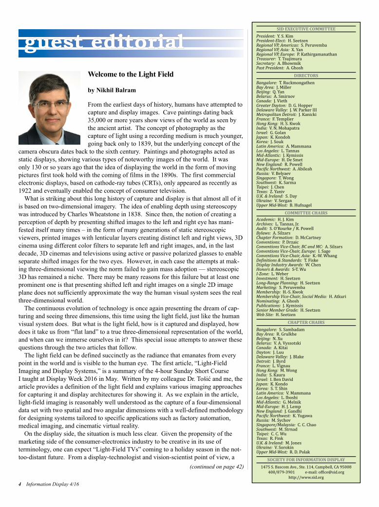
From the earliest days of history, humans have attempted tocapture and display images. Cave paintings dating back35,000 or more years show views of the world as seen bythe ancient artist. The concept of photography as the capture of light using a recording medium is much younger,going back only to 1839, but the underlying concept of the
camera obscura dates back to the sixth century. Paintings and photographs acted asstatic displays, showing various types of noteworthy images of the world. It was only 130 or so years ago that the idea of displaying the world in the form of movingpictures first took hold with the coming of films in the 1890s. The first commercialelectronic displays, based on cathode-ray tubes (CRTs), only appeared as recently as1922 and eventually enabled the concept of consumer television.
What is striking about this long history of capture and display is that almost all of itis based on two-dimensional imagery. The idea of enabling depth using stereoscopywas introduced by Charles Wheatstone in 1838. Since then, the notion of creating aperception of depth by presenting shifted images to the left and right eye has mani-fested itself many times – in the form of many generations of static stereoscopic viewers, printed images with lenticular layers creating distinct left and right views, 3Dcinema using different color filters to separate left and right images, and, in the lastdecade, 3D cinemas and televisions using active or passive polarized glasses to enableseparate shifted images for the two eyes. However, in each case the attempts at mak-ing three-dimensional viewing the norm failed to gain mass adoption — stereoscopic3D has remained a niche. There may be many reasons for this failure but at least oneprominent one is that presenting shifted left and right images on a single 2D imageplane does not sufficiently approximate the way the human visual system sees the realthree-dimensional world.
The continuous evolution of technology is once again presenting the dream of cap-turing and seeing three dimensions, this time using the light field, just like the humanvisual system does. But what is the light field, how is it captured and displayed, howdoes it take us from “flat land” to a true three-dimensional representation of the world,and when can we immerse ourselves in it? This special issue attempts to answer thesequestions through the two articles that follow.
The light field can be defined succinctly as the radiance that emanates from everypoint in the world and is visible to the human eye. The first article, “Light-FieldImaging and Display Systems,” is a summary of the 4-hour Sunday Short Course I taught at Display Week 2016 in May. Written by my colleague Dr. Tošić and me, thearticle provides a definition of the light field and explains various imaging approachesfor capturing it and display architectures for showing it. As we explain in the article,light-field imaging is reasonably well understood as the capture of a four-dimensionaldata set with two spatial and two angular dimensions with a well-defined methodologyfor designing systems tailored to specific applications such as factory automation,medical imaging, and cinematic virtual reality.
On the display side, the situation is much less clear. Given the propensity of themarketing side of the consumer-electronics industry to be creative in its use of terminology, one can expect “Light-Field TVs” coming to a holiday season in the not-too-distant future. From a display-technologist and vision-scientist point of view, a
4 Information Display 4/16
guest editorial
(continued on page 42)
SID EXECUTIVE COMMITTEEPresident: Y. S. KimPresident-Elect: H. SeetzenRegional VP, Americas: S. PeruvembaRegional VP, Asia: X. YanRegional VP, Europe: P. KathirgamanathanTreasurer: T. TsujimuraSecretary: A. BhowmikPast President: A. Ghosh
DIRECTORSBangalore: T. RuckmongathenBay Area: J. MillerBeijing: Q. YanBelarus: A. SmirnovCanada: J. ViethGreater Dayton: D. G. HopperDelaware Valley: J. W. Parker IIIMetropolitan Detroit: J. KanickiFrance: F. TemplierHong Kong: H. S. KwokIndia: V. N. MohapatraIsrael: G. GolanJapan: K. KondohKorea: J. SoukLatin America: A. MammanaLos Angeles: L. TannasMid-Atlantic: J. KymissisMid-Europe: H. De SmetNew England: R. PowellPacific Northwest: A. AbileahRussia: V. BelyaevSingapore: T. WongSouthwest: K. SarmaTaipei: J. ChenTexas: Z. YanivU.K. & Ireland: S. DayUkraine: V. SerganUpper Mid-West: B. Hufnagel
COMMITTEE CHAIRSAcademic: H. J. KimArchives: L. Tannas, Jr.Audit: S. O’Rourke / R. PowellBylaws: A. SilzarsChapter Formation: D. McCartneyConventions: P. DrzaicConventions Vice-Chair, BC and MC: A. SilzarsConventions Vice-Chair, Europe: I. SageConventions Vice-Chair, Asia: K.-W. WhangDefinitions & Standards: T. FiskeDisplay Industry Awards: W. ChenHonors & Awards: S-T. WuI-Zone: L. WeberInvestment: H. SeetzenLong-Range Planning: H. SeetzenMarketing: S. PeruvembaMembership: H.-S. KwokMembership Vice-Chair, Social Media: H. AtkuriNominating: A. GhoshPublications: J. KymissisSenior Member Grade: H. SeetzenWeb Site: H. Seetzen
CHAPTER CHAIRSBangalore: S. SambadamBay Area: R. GrulkheBeijing: N. XuBelarus: V. A. VyssotskiCanada: A. KitaiDayton: J. LuuDelaware Valley: J. BlakeDetroit: J. ByrdFrance: L. VignauHong Kong: M. WongIndia: S. KauraIsrael: I. Ben DavidJapan: K. KondoKorea: S. T. ShinLatin America: V. MammanaLos Angeles: L. IboshiMid-Atlantic: G. MelnikMid-Europe: H. J. LempNew England: J. GandhiPacific Northwest: K. YugawaRussia: M. SychovSingapore/Malaysia: C. C. ChaoSouthwest: M. StrnadTaipei: C. C. WuTexas: R. FinkU.K. & Ireland: M. JonesUkraine: V. SorokinUpper Mid-West: R. D. Polak
SOCIETY FOR INFORMATION DISPLAY1475 S. Bascom Ave., Ste. 114, Campbell, CA 95008408/879-3901 e-mail: [email protected]://www.sid.org
ID Guest Editorial Issue4 p4,42_Layout 1 7/10/2016 4:50 PM Page 4
Your specialty chemical solutions provider.
800.888.0698 | ellsworth.com
We’re insideyour
electronics(but in a good way).
Sealants
Solder
ConformalCoatings
Thermal Materials
Tapes
Adhesives
Download the presentation
Consumer Electronics:Design with Flexibility for Reliability
from Dow Corning & Ellsworth Adhesives
Learn to design lighter, thinner & more durable electronics.
Available at ellsworth.com
• Unique display lines• German engineering• Intelligent TFT solutions• ePaper, OLED, LCD• Innovative chip-on-glass• RS232, I2C, SPI, USB• Easy to use• Evaluation Kits• No lead time• Direct support
ELECTRONIC ASSEMBLY GmbH [email protected] www.lcd-module.com
jOIN OUR DISPLay wORLDwww.masterbond.com
Hackensack, NJ 07601 USA +1.201.343.8983 • [email protected]
see in a newlight
Light Curing Adhesives
• Environmentally friendly• Rapid cures• Require no mixing• Eliminate waste• Lower processing costs
LED and UV curing
THE light field is an old concept that hasbecome increasingly relevant in recent timesbecause of the advances made in digital andoptical technologies and an improved understanding of how the human visual system perceives and interprets the world.This article provides a brief introduction tothe concept and an overview of how lightfields are captured (imaged) and displayed.Light-field imaging and display are oftentreated as separate areas because theapproach, rigor of the design process, andclarity of possible applications and valuepropositions are quite different, with imagingbeing much further advanced in somerespects. At the same time, at a conceptuallevel, one can view a light-field display as thereverse path of light-field imaging, and thisway of thinking can be helpful in the designof either type of system, when practical trade-offs and limits have to be contemplated.
Introduction to Light FieldsUnlike a photograph that represents visualinformation as a projection of light on a 2Dimage plane, a light field represents the worldaround us through a set of light rays that fillup the 3D space. Even though not formallycalled the “light field,” this concept dates backto the beginning of the 16th century and to
Leonardo da Vinci, who referred to these setsof rays as “radiant pyramids.” The introduc-tion of the term “light fields” came four centuries later, in 1936 when Arun Gershundefined the light field as the amount of lighttraveling in every direction through everypoint in space. In 1991, Adelson and Bergen1
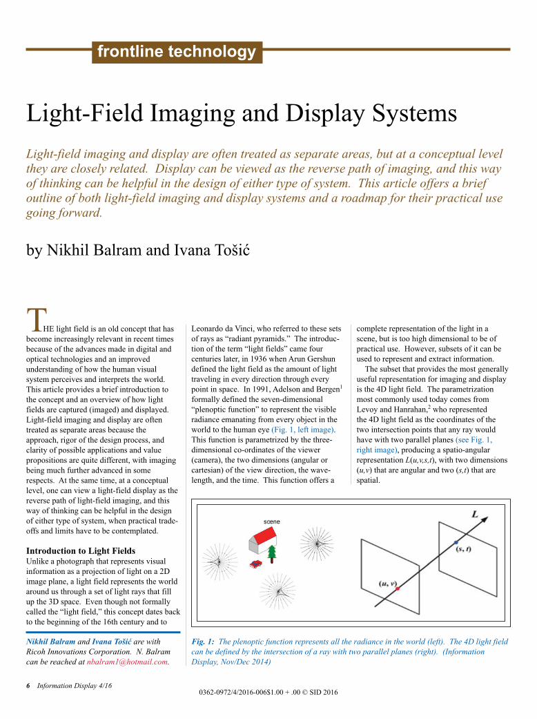
formally defined the seven-dimensional“plenoptic function” to represent the visibleradiance emanating from every object in theworld to the human eye (Fig. 1, left image).This function is parametrized by the three-dimensional co-ordinates of the viewer (camera), the two dimensions (angular orcartesian) of the view direction, the wave-length, and the time. This function offers a
complete representation of the light in a scene, but is too high dimensional to be ofpractical use. However, subsets of it can beused to represent and extract information.
The subset that provides the most generallyuseful representation for imaging and displayis the 4D light field. The parametrizationmost commonly used today comes fromLevoy and Hanrahan,2 who represented the 4D light field as the coordinates of the two intersection points that any ray wouldhave with two parallel planes (see Fig. 1, right image), producing a spatio-angular representation L(u,v,s,t), with two dimensions(u,v) that are angular and two (s,t) that arespatial.
Light-Field Imaging and Display SystemsLight-field imaging and display are often treated as separate areas, but at a conceptual levelthey are closely related. Display can be viewed as the reverse path of imaging, and this wayof thinking can be helpful in the design of either type of system. This article offers a brief outline of both light-field imaging and display systems and a roadmap for their practical usegoing forward.
by Nikhil Balram and Ivana Tošić
Nikhil Balram and Ivana Tošić are withRicoh Innovations Corporation. N. Balramcan be reached at [email protected].
6 Information Display 4/160362-0972/4/2016-006$1.00 + .00 © SID 2016
frontline technology
Fig. 1: The plenoptic function represents all the radiance in the world (left). The 4D light fieldcan be defined by the intersection of a ray with two parallel planes (right). (Information Display, Nov/Dec 2014)
ID Balram p6-13_Layout 1 7/10/2016 5:25 PM Page 6

Light-Field ImagingThe light field contains a wealth of usefulinformation that can be acquired in its entiretyor extracted in the form of application-specificsubsets. Two fundamental approaches foracquisition of the light field use a two-dimensional array of synchronized cameras ora single camera with a two-dimensional arrayof microlenses between the main lens and theimage sensor (see Figs. 2 and 3).
The early approaches to light-field acquisi-tion used the concept of a camera array, either created temporally by moving a single camera2
for static imaging or more generally with a physical N × N array.3 The camera array approach provides high spatial resolution (since each camera has a K × K sensor, where K could be a large number), good image quality, and a broad range of distances at which object depths can be resolved (by constructing an appropri-ately wide baseline between the left/top versus the right/bottom views). The disadvantagesare the significant bulk of the system, the dif-ficulty in synchronizing and calibrating acrossmany separate cameras, and the limited view resolution (since there is a physical limit to how closely together the cameras can be placed).
Subsequent approaches to light-field acqui-sition focused on a compact single camerathat uses a K × K array of microlenses placedin between the image sensor and main lens ofa conventional camera; an example of thisapproach is described in a 2005 TechnicalReport CSTR.4 The microlens array (MLA)can be placed at different positions betweenthe main lens and image sensor, but the mostcommon and (computationally) convenientapproach places the MLA at the focal plane ofthe main lens and the image sensor at thefocal plane of the MLA. This results in thecapturing of N × N views by the correspon-ding sensor elements under each microlens,and these sub-images can be processed to pro-duce a set of N × N images in which each rep-resents a unique view with a spatial resolutionof K x K (see illustration in Fig. 4). Thisapproach provides the advantages of a con-venient portable form factor, high density ofviews (since N can be made reasonably largefor a high-resolution image sensor), and theadded option of capturing multi-spectral content by inserting a multi-spectral filter infront of the main lens.5 The disadvantages arethe reduced spatial resolution (which is
defined by K, the number of elements in eachdimension of the MLA), and the very smallbaseline between the left/top and right/bottomviews, which limits depth imaging to nearbyobjects.
The camera-array approach was primarilyused in research between 1995 and 2005,while various vertical application solutionswere developed based on the single camerawith the MLA approach, with, for example,Lytro introducing a consumer camera in 2011and Raytrix and Ricoh introducing industrialcameras in 2010 and 2014, respectively (seeFig. 2). However, the recent resurgence ofinterest in consumer virtual-reality (VR)HMDs has motivated the development ofspherical camera arrays as a means of captur-ing the 360° light field and processing it toprovide cinematic VR content - see the examples of Jaunt ONE and Lytro Immerge inFig. 2.
Figure 3 shows the duality between the camera array and the MLA + sensorapproaches. It is interesting to note the reversal that occurs between the roles of the N × N and K × K parameters. A similar typeof duality exists in the case of fundamental
Information Display 4/16 7
Fig. 2: Light-field imaging can use an array of cameras arranged in a rectangular or spherical configuration (left) or a compact single camerathat uses a microlens array (right).
ID Balram p6-13_Layout 1 7/10/2016 5:25 PM Page 7

light-field-display architectures, where thecamera array is replaced by an array of displays such as projectors or microdisplays,and the MLA + sensor is replaced by the MLA+ display.
As shown in Fig. 5, a robust system designmethodology is used to design light-fieldimaging systems that are optimized for specific vertical applications; for example, asdescribed in a 2013 paper by Berkner et al.7The major elements of the system are modeled and optimized through the use ofperformance metrics that are specific for eachapplication. For example, in the case of acolor inspection camera, the performance metric is the error between the computed and
frontline technology
8 Information Display 4/16
Fig. 4: The light-field camera architectureincludes the main lens, microlens array, and detector (sensor). The raw image has to beprocessed to produce sub-images representingthe different views.
Fig. 3: Depicted above is the duality between the array-of-cameras approach (left) and the single-camera-with-microlens-array approach (right)(Information Display, Nov/Dec 2015).6
ID Balram p6-13_Layout 1 7/10/2016 5:25 PM Page 8

known chromatic properties of a color calibra-tion pattern.
The most important components of light-field imaging systems are:
● Calibration● 3D (depth) estimation● Resolution enhancementa
● Multi-spectral image processingb
We will briefly discuss the first three here.More detail can be found in the references.
Calibration: This refers to the process oftaking raw data acquired by the sensor andconverting it into a 4D (u,v,s,t) light-field representation. This involves a number ofsteps.8 The first step, which has to be done only once for a given camera instance, includeslocating lenslet image centers by using awhite test image, estimating grid parameters, and building and saving the lenslet grid model. The additional steps, which have to be donefor each acquired image, include some or allof the following: demosaicing to fill in com-plete R, G, B values from the Bayer patterndata; correcting vignetting by normalizingwith the white image; resampling the imageonto an integer grid using 1D or 2D interpola-tion; converting the grid from hexagonal toorthogonal (if hexagonal MLA is used); andslicing the results into a 4D light field L(i,j,k,l)where (k,l) are the coordinates of each super-pixel (representing one spatial point) and (i,j)are coordinates representing points (views)inside each superpixel. Thereafter, a systemmodel needs to be estimated to allow conver-sion from homogenous coordinates to ray
space coordinates (u,v,s,t), including adjust-ment for distortions in the real system.
3D (depth) estimation: This refers to theprocess of estimating the depth of a scene.Depending on the needs of the specific appli-cation, a generative model can be used to estimate the depth of planar scene layers9 or, alternatively, a dense depth estimation approach can be used to assign depth to each spatialposition10,11 (see Fig. 6).
The latter uses 2D light-field slices calledepipolar plane images (EPIs) that have onespatial and one angular dimension. Each EPIcontains linear structures called “rays” thatrepresent the radiance properties of a spatialpoint viewed from different angles. Pointsthat lie on the focal plane of the main lenshave negligible shifts across views and formvertical rays, whereas those that are in front orbehind the focal plane show significant devia-
Information Display 4/16 9
Fig. 5: In a system design model for light-field imaging, each major element of the system is modeled and the appropriate performance metric ischosen for each specific application. An iterative optimization process is used to design the optimal system for that application.7
Fig. 6: A 3D estimation (dense depth-map generation) process using the LISAD approach.10
aIf more resolution is needed than provided by thenative resolution of the MLA.bIf the application calls for the use of wavelengthsthat are different from the usual R, G, and B.
ID Balram p6-13_Layout 1 7/10/2016 5:25 PM Page 9
tion and form slanted rays. Consequently, theangle of a ray provides information about thedepth of the corresponding point. In 2014,Tošić et al.10 identified rays and their anglesby localizing extrema in a novel scale-depthspace representation of light fields, calledLISAD (Light Field Scale And Depth), which is built upon the first and second derivatives of a Ray Gaussian kernel. Rays and their angles were further combined and processed to develop a dense depth map of a given 3D scene.
Enhanced resolution: Spatial resolution isa challenge for plenoptic systems becausethey trade it off to obtain a mixture of spatialand angular information. Higher resolutioncan be obtained physically by reducing themicrolens diameter (and corresponding sensorpitch) and increasing the number of micro-lenses in the array or by increasing the sensorsize to allow more micro-lenses of the samediameter. Either approach has tradeoffs – theformer runs into diffraction limits and sensornoise issues; the latter makes the systemlarger and more expensive.
Resolution can also be increased algorith-mically by using advanced super-resolutionalgorithms, but these provide limited improve-ments with the simple plenoptic architecturethat is commonly used. A different architec-ture, sometimes called “focused plenoptic,”12
that moves the MLA out of the focal plane ofthe main lens, thereby spreading rays fromeach object into adjacent superpixels, enablesthe use of super-resolution algorithms to provide significantly higher resolution, but atthe cost of reduced angular resolution andadditional complexity.
Figure 2 shows some prominent examplesof light-field imaging systems currently beingused in various vertical applications. We canexpect a lot more systems to join this list infuture.
Light-Field DisplaysLight-field displays offer the promise of displaying realistic three-dimensional contentin a way that appears natural to the humanvisual system. By applying the Turing test todisplays, the ultimate goal would be a displaythat looks like a window through which thereal world is visible. If a light field representsthe radiance in a real scene that is visible tothe human eye, then a display that provides alight field should create the same sensationand satisfy a Turing-like test. The displayshould provide the same type of depth cues
that the human visual system gets from thereal world. Most of these cues are monocular,falling into the categories of geometry, color,and focus, and are satisfied by properly cap-tured or synthesized 2D images and video.
The two major binocular cues are vergenceand retinal disparity. These can be providedby simple stereoscopic 3D systems that usesingle or dual 2D screens to show left- andright-eye images that are appropriately shifted according to their desired depth placement. But a fundamental, and now well known, problemoccurs because of the coupling between thebinocular cue of vergence (the two eyes rotat-ing appropriately to make their lines of sightintersect at the 3D point at which the viewedobject is placed) and the monocular cue of accommodation (the lens of each eye adjusting to focus on the same 3D point). This strongcoupling is broken by the unnatural presenta-tion of 3D content on a single display plane.Studies by researchers such as Banks et al.13
have shown the significant discomfort andviewing problems caused by this cue conflict.
In order to offer natural viewing of 3D content, light-field displays can be used tocreate an accommodation response that is
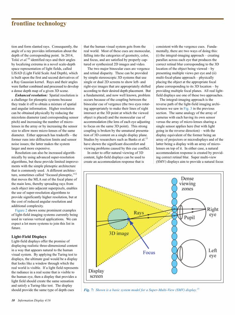
consistent with the vergence cues. Funda-mentally, there are two ways of doing this: (i) the integral-imaging approach – creatingparallax across each eye that produces the correct retinal blur corresponding to the 3Dlocation of the object being viewed – by presenting multiple views per eye and (ii)multi-focal-plane approach – physically placing the object at the appropriate focalplane corresponding to its 3D location – byproviding multiple focal planes. All real light-field displays use one of these two approaches.
The integral-imaging approach is thereverse path of the light-field imaging archi-tectures we saw in Fig. 3 in the previous section. The same analogy of the array ofcameras with each having its own sensor versus the array of micro-lenses sharing a single sensor applies here (but with lightgoing in the reverse direction) – with the display equivalent of the former being anarray of projectors or microdisplays and of thelatter being a display with an array of micro-lenses on top of it. In either case, a naturalaccommodation response is created by provid-ing correct retinal blur. Super multi-view(SMV) displays aim to provide a natural focus
frontline technology
10 Information Display 4/16
Fig. 7: Shown is a basic system model for a Super-Multi-View (SMV) display.15
ID Balram p6-13_Layout 1 7/10/2016 5:25 PM Page 10
cue by providing at least two views to each eye. The rationale for two views being sufficient is based on the simple trigonometric construction shown in Fig. 7 developed by Takaki et al.14,15
However, it is not clear how sensitive this two-view minimum is to viewing dis-
tance or whether it creates retinal blur thatcan provide appropriate size and distancecues. It is likely that a larger number ofviews per eye are needed and the true mini-mum number that provides natural retinalblur is not known yet, although there has
been some work in modeling of parallax-barrier-based light-field displays16 that suggests how a theoretical foundation couldbe developed to answer this question. Thereis a clear need for further user studies on this topic.
Information Display 4/16 11
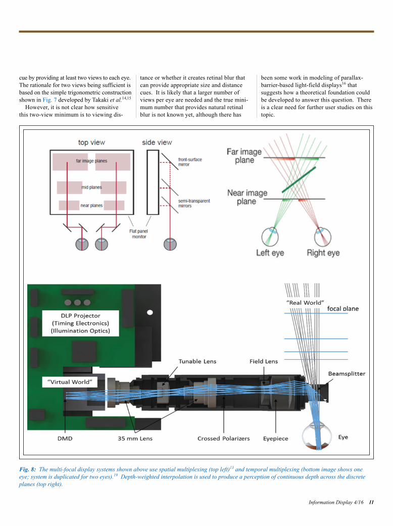
Fig. 8: The multi-focal display systems shown above use spatial multiplexing (top left)13 and temporal multiplexing (bottom image shows oneeye; system is duplicated for two eyes).19 Depth-weighted interpolation is used to produce a perception of continuous depth across the discreteplanes (top right).
ID Balram p6-13_Layout 1 7/10/2016 5:25 PM Page 11
The multi-focal-plane approach is a practi-cal approximation of a light-field display thatonly works for a single viewpoint at a time.Spatial or temporal multiplexing can be usedto create multiple focal planes that placeobjects at appropriate distances to be consis-tent with vergence. Akeley17 built a three-plane system using spatial multiplexing of asingle high-resolution display and demon-strated that it could provide consistent vergence and accommodation cues thatenabled comfortable viewing of 3D content.He showed that depth-weighted linear inter-polation could be used to place objects inbetween the display planes, and his work suggests that 16 or fewer planes might be
sufficient to provide an appearance of contin-uous depth. Schowengerdt et al.,18 Llull et al.,19 and others have used temporal multi-plexing instead to produce the effect of multi-ple planes. Figure 8 shows the spatial and temporal approaches used by Akeley and Llull et al., respectively, and the linear inter-polation used to provide continuous depth inbetween the planes.
More sophisticated and higher-performingdepth-value generation approaches based onnon-linear optimization of functions that consider the content and the visual systemresponse have been developed recently.20–22
As is often the case, there is a tradeoff between image quality and computational requirements.
Light-field displays can be divided into twodifferent types based on fundamentally differ-ent use cases: group/multi-user displays andpersonal (near-to-eye/head-mounted) displays.Group displays are discussed briefly in thispaper, while head-mounted displays for VRand AR are the subject of the article by HongHua that also appears in this issue.
Three major types of group/multi-user displays include scanning, multi-projector,and multi-layer. The first two are discussed in detail in Liu’s overview paper,23 and thethird is discussed in articles such as one byWetzstein24 published in 2015.
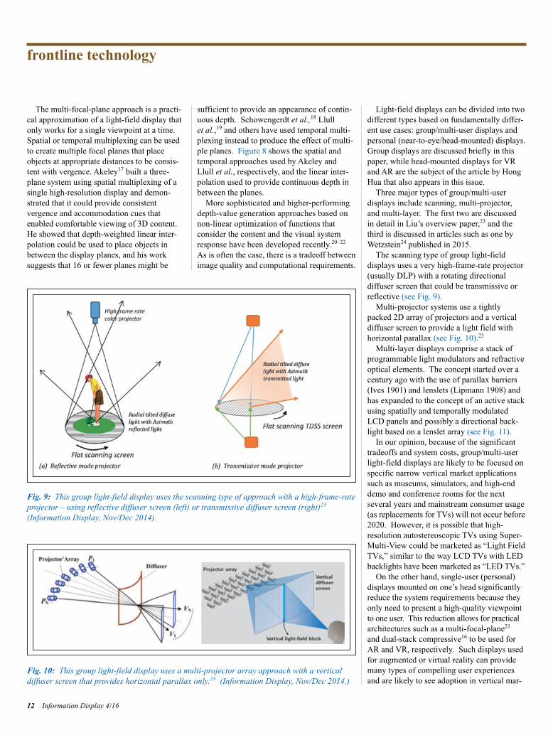
The scanning type of group light-field displays uses a very high-frame-rate projector(usually DLP) with a rotating directional diffuser screen that could be transmissive orreflective (see Fig. 9).
Multi-projector systems use a tightlypacked 2D array of projectors and a verticaldiffuser screen to provide a light field withhorizontal parallax (see Fig. 10).23
Multi-layer displays comprise a stack ofprogrammable light modulators and refractiveoptical elements. The concept started over acentury ago with the use of parallax barriers(Ives 1901) and lenslets (Lipmann 1908) andhas expanded to the concept of an active stackusing spatially and temporally modulatedLCD panels and possibly a directional back-light based on a lenslet array (see Fig. 11).
In our opinion, because of the significanttradeoffs and system costs, group/multi-userlight-field displays are likely to be focused onspecific narrow vertical market applicationssuch as museums, simulators, and high-enddemo and conference rooms for the next several years and mainstream consumer usage (as replacements for TVs) will not occur before 2020. However, it is possible that high-resolution autostereoscopic TVs using Super-Multi-View could be marketed as “Light FieldTVs,” similar to the way LCD TVs with LED backlights have been marketed as “LED TVs.”
On the other hand, single-user (personal)displays mounted on one’s head significantlyreduce the system requirements because theyonly need to present a high-quality viewpointto one user. This reduction allows for practicalarchitectures such as a multi-focal-plane21
and dual-stack compressive16 to be used forAR and VR, respectively. Such displays usedfor augmented or virtual reality can providemany types of compelling user experiencesand are likely to see adoption in vertical mar-
frontline technology
12 Information Display 4/16
Fig. 9: This group light-field display uses the scanning type of approach with a high-frame-rateprojector – using reflective diffuser screen (left) or transmissive diffuser screen (right)23 (Information Display, Nov/Dec 2014).
Fig. 10: This group light-field display uses a multi-projector array approach with a vertical diffuser screen that provides horizontal parallax only.23 (Information Display, Nov/Dec 2014.)
ID Balram p6-13_Layout 1 7/10/2016 5:25 PM Page 12

ket applications and broader consumer seg-ments such as entertainment, gaming, andeducation within the next 5 years.24,27 Sincethe quality of user experience will be of paramount importance in the successful andwidespread adoption of these systems, light-field displays are likely to play a major role.For this reason, the next article in this issue,written by Hong Hua, is focused on recentadvances in light-field displays for VR andAR HMDs.
AcknowledgmentsStanford is a registered trademark of StanfordUniversity. The Lytro and the Lytro logo aretrademarks of Lytro, Inc., registered in multiplecountries. Raytrix and the Raytrix logo areregistered trademarks of the Raytrix GmbH.Jaunt ONE is a registered trademark of Jaunt,Inc.
References1E. H. Adelson and J. R. Bergen, “The plenop-tic function and the elements of early vision,”Computational Models of Visual Proc. (MITPress, 1991).2M. Levoy and P. Hanrahan, “Light field rendering,” SIGGRAPH 1996.3B. Wilburn, M. Smulski, H. K. Lee, and M.Horowitz, “The Light Field Video Camera,”Proc. Media Processors, SPIE ElectronicImaging (2002).4R. Ng, M. Levoy, M. Bredif, and G. Duval,“Light field photography with a handheld
plenoptic camera,” Technical Report CSTR(2005).5R. Horstmeyer, G. Euliss, R. Athale, and M. Levoy, “Flexible multimodal camera withlight field architecture,” IEEE InternationalConference on Computational Photography,2009.6K. Akeley, “Light-field imaging approachescommercial viability,” Information Display 6,No. 15 (Nov./Dec. 2015).7K. Berkner, L. Meng, S. A. Shroff, and I. Tošić, “Understanding the design space of a plenoptic camera through an end-to-end system model,” OSA Applied Imaging Congress (June 2013).8D. G. Dansereau, O. Pizarro, and S. B.Williams, “Decoding, calibration and rectifi-cation for lenselet-based plenoptic cameras,”CVPR (2013).9Y. Lin, I. Tošić, and K. Berkner, “Occlusion-aware layered scene recovery from lightfields,” Proceedings of IEEE ICIP (2013).10I. Tošić and K. Berkner, “Light field scale-depth space transform for dense depth estima-tion,” CVPR Workshops (June 2014).11I. Tošić and K. Berkner, “3D KeypointDetection by Light Field Scale-Depth SpaceAnalysis,” ICIP (October 2014).12T. Georgiev, “The focused plenoptic camera,” http://www.tgeorgiev.net/EG10/ Focused.pdf13M. S. Banks, K. Akeley, D. M. Hoffman,and A. R. Girshick, “Conflicting focus cues in stereoscopic displays,” Information Display (July 2008).
14Y. Takaki, “High-density directional displayfor generating natural three-dimensionalimages,” Proc. IEEE 94, 3 (2006).15Y. Takaki, K. Tanaka, and J. Nakamura,“Super multi-view display with a lower resolution flat-panel display,” Opt. Express19, 5 (Feb. 2011). 16F. C. Huang, G. Wetzstein, B. Barsky, andR. Rasker, “Eyeglasses-free display: towardscorrecting visual aberrations with computa-tional light field displays,” SIGGRAPH 2014.17K. Akeley, “Achieving near-correct focuscues using multiple image planes,” Ph.D. thesis (Stanford University, 2004)18B. T. Schowengerdt and E. J. Seibel, “TrueThree-Dimensional Displays that AllowViewers to Dynamically Shift Accommoda-tion, Bringing Objects Displayed at DifferentViewing Distances Into and Out of Focus,”Cyperpsychology & Behavior (2004).19P. Llull, N. Bedard, W. Wu, I. Tošić, K. Berkner, and N. Balram, “Design and optimization of a near-eye multi-focal displaysystem for augmented reality,” COSI (June2015).20R. Narain, R. A. Albert, A. Bulbul, G. J.Ward, M. S. Banks, and J. F. O. Brien, “Opti-mal presentation of imagery with focus cueson multi-plane displays,” ACM Trans. Graphics34, No. 4 (August 2015).21W. Wu, I. Tošić, N. Bedard, P. Llull, K. Berkner, and N. Balram, “Near-eye displayof light fields,” IDW 201522W. Wu, I. Tošić, N. Bedard, P. Llull, K. Berkner, and N. Balram, “Content-adaptivefocus configuration for near-eye multi-focaldisplays,” ICME 2016.23X. Liu and H. Li, “The progress of lightfield 3-D displays,” Information Display 30,No. 6 (Nov/Dec 2014).24G. Wetzstein, “Why people should careabout light-field displays,” Information Display 31, No. 2 (March/April, 2015).25G. Wetzstein. D. Lanman, M. Hirsch, and R. Raskar, “Tensor displays: compressivelight field synthesis using multi-layer displayswith directional backlighting,” SIGGRAPH2012.26F. C. Huang, K. Chen, and G. Wetzstein,“The light field stereoscope: immersive com-puter graphics via factored near-eye light fielddisplays with focus cues,” SIGGRAPH 2015.27W. Wu, K. Berkner, I. Tosic, and N. Balram,“Personal near-eye light field display,” Information Display 30, No. 6. (Nov/Dec2014). n
Information Display 4/16 13
Fig. 11: This group light-field display uses a multi-layer approach – a compressive displayemploying a stack of LCD panels with directional (left side) or regular backlight.25 A directional backlight is created by using a lenticular lens array on top of the bottom LCD panel,as shown on the left side of the figure.
ID Balram p6-13_Layout 1 7/10/2016 5:25 PM Page 13

HEAD-MOUNTED DISPLAYS(HMDs) have drawn significant interest inrecent years for a broad range of consumerapplications.1,2 For instance, a lightweightoptical see-through head-mounted display(OST-HMD), which enables optical super-position of two-dimensional (2D) or three-dimensional (3D) digital information onto auser’s direct view of the physical world andmaintains see-through vision to the real world,is one of the key enabling technologies foraugmented-reality (AR) applications. HMDsare viewed as a transformative technology, enabling new ways of accessing and perceiving digital information essential to our daily lives.In recent years, significant advancements havebeen made toward the development of unob-trusive AR displays that integrate the functions of OST-HMDs, smart phones, and variousmobile computing functions. A few commer-cial AR displays have demonstrated very compact and lightweight form factors with the potential of widespread public use. Forinstance, Google Glass3 is a very compactlightweight monocular display that provides
encumbrance-free instant access to digitalinformation, while the Epson Moverio4 andMicrosoft Hololens5 are binocular displaysproviding the benefits of stereoscopic viewing.On the virtual-reality (VR) side, severalimmersive HMD products are commerciallydeployed or close to commercial launch.
Despite tremendous progress, minimizingvisual discomfort involved in wearing HMDsremains an unsolved challenge. Most existingHMDs utilize 2D flat-image sources located ata fixed distance from the eye, and thus lackthe ability to render correct focus cues(including accommodation and retinal imageblurring effects) for digital information. Theresulting well-known vergence–accommodationconflict (VAC) problem in both VR and ARsystems is considered a key contributing factor to visual discomfort. Many studieshave investigated the artifacts of the incor-rectly rendered focus cues in conventionalstereoscopic 3D displays.6–9 Incorrect focuscues may contribute to the two commonly recognized issues: distorted depth perceptionand visual discomfort, including diplopicvision, visual fatigue, and degradation in oculomotor response.
Several methods have been explored inHMD designs to address the VAC problem
and approximate the visual effects created byfocus cues when viewing a real-world scene.Examples include a vari-focal-plane displaythat dynamically compensates the focal dis-tance of a single-plane display based on aviewer’s fixation point,10,11 a multi-focal-plane (MFP) display method that creates astack of focal planes in space- or time-multi-plexing fashion,12-17 a micro-integral imaging
Advances in Head-Mounted Light-FieldDisplays for Virtual and Augmented RealityHead-mounted light-field displays render a true 3D scene by sampling either the projectionsof the 3D scene at different depths or the directions of the light rays apparently emitted by the3D scene and viewed from different eye positions. Head-mounted light-field displays arecapable of rendering correct or nearly correct focus cues and addressing the well-known vergence–accommodation mismatch problems of conventional virtual- and augmented-realitydisplays.
by Hong Hua
Hong Hua is with the 3DVIS Lab, College ofOptical Sciences, University of Arizona. Shecan be reached at [email protected].
14 Information Display 4/160362-0972/4/2016-014$1.00 + .00 © SID 2016
frontline technology
Fig. 1: This schematic shows the multi-focal-plane display method.
ID Hua p14-21_Layout 1 7/10/2016 6:20 PM Page 14

(micro-Inl) method that reconstructs the full-parallax light fields of a 3D scene throughpinhole or lenslet array18,19 and a multi-layermethod, which utilizes multi-layers of spatiallight modulators (SLMs) to modulate a uni-form backlight and render apparently direc-tional light rays.20,21 To some extent, thesemethods are able to overcome the VAC problem with different levels of limitations.In this article, we focus on reviewing recentadvancements of head-mounted light-fielddisplays for VR and AR applications, whichincorporate some of these methods.
Multi-Focal-Plane Approach towardHead-Mounted Light-Field DisplaysA multi-focal-plane (MFP) display creates astack of discrete focal planes dividing anextended 3D scene volume into multiplezones along the visual axis, each of whichonly renders 3D objects nearby.12–17 Figure 1shows a schematic diagram of a dual-focal-plane example. An MFP-based display maybe implemented either by spatially multiplexinga stack of 2D displays12,13 or by fast switchingthe focal distance of a single 2D displaysequentially using a high-speed vari-focal element (VFE) in synchronization with theframe rendering of multi-focal images.14–17
For instance, Akeley et al. demonstrated aproof-of-concept bench prototype of a three-focal-plane display covering a fixed depthrange from 0.311 to 0.536 m by dividing aflat-panel display into three focal planesthrough three beamsplitters placed at different
distances from the viewer. McQuaide et al.demonstrated a dual-focal-plane retinal scan-ning display in which a 2D image is generatedon a pixel-by-pixel basis by raster scanning alaser beam. The focus of the laser beam isvaried through the use of a deformable mem-brane mirror device (DMMD), and the focuscues can be adjusted at every pixel if theDMMD operates at a high enough speed.14
More recently, Schowengerdt et al. suggesteda spatial-multiplexing retinal scanning displayby replacing a single fiber source with a fiberarray to produce a multi-focal bundle ofbeams.22 By using a liquid lens as the VFEand an OLED microdisplay as the imagesource, Liu and Hua demonstrated the firstprototype of a dual-focal-plane optical see-through AR display, which maintains a non-obstructive see-through view to the realworld.15 Love et al. demonstrated a prototypewith four fixed focal planes generated throughbirefringent lenses as the VFEs and high-refresh-rate CRTs as the image sources.16
Wu et al. recently demonstrated an MFP prototype by exploring dynamically variableplanes adapted from contents.23
In these conventional MFP display methods,a large number of focal planes and small dioptric spacing are desirable for achievingaccurate focus cues. It was suggested that thedioptric spacing between adjacent focal planesshould be 1/7 diopters to achieve 1 arc-minutespatial resolution.12 At this spacing, 28 focalplanes are needed to cover the depth rangefrom infinity to 4 diopters. A depth-fused 3D
(DFD) multi-focal plane (DFD-MFP) displaymethod was proposed (Fig. 2), through whichthe number of necessary focal planes is effec-tively reduced to an affordable level.17,24–29
Liu and Hua,17 Hu and Hua,25 and Hu26
presented a framework for a DFD-MFP systemdesign in which the focal-plane spacing andthe fusion functions are optimized to maxi-mize the contrast magnitude and gradient ofthe retinal image fused by the two imagesoverlapping along the visual axis. This frame-work avoids a conflict of focusing cues andcreates a smooth contrast gradient that helpsto stimulate and stabilize the eye accommoda-tion response.
Figure 3 shows the optical layout of amonocular OST-HMD system based on theDFD-MFP method.27 Each monocular setupconsists of two parts: the composite opticalsee-though eyepiece and the image-generationsubsystem (IGS). The composite eyepiece[Fig. 3(a)] consists of a wedge-shapedfreeform eyepiece, a free-form see-throughcompensator lens, and a cylindrical lens.27
The IGS [Fig. 3(b)] achieves the core functionof generating the multi-focal-plane contents.It consists of a 0.7-in. high-speed digital-mirror-device (DMD) microdisplay, a deformablemembrane mirror device (DMMD), and relaylens groups. The DMD display, illuminatedby an RGB LED light source (not shown), isfirst magnified by two field lenses and thenrelayed by a double-pass double-telecentriclens group, forming an intermediate imagebetween the IGS and the eyepiece. By changing
Information Display 4/16 15
Fig. 2: In this schematic model of a DFD-MFP display, the luminance ratio between the front and back images is modulated to change the perceived depth of the fused image to be near to the front image plane (a) and near the back image (b).
(a) (b)
ID Hua p14-21_Layout 1 7/10/2016 6:20 PM Page 15

the optical power of the DMMD, the inter-mediate image shifts axially with respect tothe eyepiece without magnification change,while the accommodation cue of the HMD isvaried from far to close. The optical power ofthe DMMD can change at a speed as fast as 1 kHz; thus, virtual images at multiple focaldistances can be multiplexed by rapidlychanging the optical power of the DMMD.
Figure 4(a) shows the actual setup built onan optical bench.27 Figures 4(b) and 4(c)show photos of a 3D scene rendered by thevirtual display and captured with a cameraplaced at the exit pupil position.27 Six focalplanes were dynamically formed at 3.0, 2.4,1.8, 1.2, 0.6, and 0.0 diopters, respectively, atan overall refresh rate of 60 Hz. The 3Dscene consists of a green floor grid extendingfrom 3.0 to 0.6 diopters, a green wall grid at0.6 diopters having a University of Arizonalogo on it, and a grating target extending from3.0 to 0.6 diopters, as well as a College ofOptical Sciences logo placed at the 3.0 diopter
end. Each focal plane displays a different partof the 3D scene. By incorporating non-lineardepth-fusing functions,25 this 3D scene wasrendered continuously by five of the focalplanes. Figure 4(b) shows the image with thecamera focusing at a 3-diopter distance (near),and Fig. 4(c) shows the image focusing at a0.6-diopter distance (far). Natural focus cueswere clearly demonstrated, and high-contrast targets were correctly fused across focal planes, which visually validated the depth-fusion dis-play method. The optical see-through path of the prototype also achieved superb performance.
Overall, the prototype adequately demon-strated the capability of the DFD-MFP displaymethod for rendering nearly correct focuscues, with the potential for addressing theVAC. However, the technology suffers fromseveral critical technical obstacles to becominga viable solution for truly wearable light-fieldAR displays. The first major obstacle isminiaturization of the technology. Due to thelimitations of several enabling technologies,
including the high-speed displays and vari-focal element, the current prototype wasimplemented in the form of a bench prototype,occupying a volume of nearly 500 × 300 ×100 mm. The second major obstacle is real-time rendering and display. The prototype islimited by the current capabilities of high-speed display technology and display–computerinterfaces and is unable to render and displaysix or more frames of high-resolution full-color images at a speed several times fasterthan a standard single-frame display. Trans-forming this display method into a compactwearable solution requires several technicalinnovations.
Integral-Imaging (InI) Based Head-Mounted Light-Field DisplaysInstead of creating a stack of focal planes tosample the depth volume, an integral-imaging(InI) based display method reconstructs thefull-parallax light fields of a 3D scene bydensely sampling the different directions of
frontline technology
16 Information Display 4/16
Fig. 3: (a) A top-view optical layout of the right-eye module of a DFD-MFP system includes (b) a detailed layout of the image-generation sub-system.27
ID Hua p14-21_Layout 1 7/10/2016 6:20 PM Page 16

the light rays apparently emitted by a 3Dscene.30 A simple InI display typically consists of a display panel and a microlensarray (MLA). The display renders a set of 2Delemental images, each of which represents adifferent perspective of a 3D scene. The MLAcreates the perception of a 3D scene thatappears to emit light and occupy 3D space,through the intersection of the ray bundlesemitted by the corresponding pixels in the elemental images. The InI-based displayallows the reconstruction of a 3D shape withfull-parallax information in both horizontal
and vertical directions. The simple opticalarchitecture of InI makes it attractive to integrate with an HMD optical system to create a wearable true 3D display.
Lanman et al. demonstrated a non-see-through light-field display by directly placingan MLA and an OLED microdisplay in frontof the eyes to render the light field of a 3Dscene for VR applications.19 The prototypesystem, shown in Fig. 5, had a field of view ofabout 29° × 16° and a spatial resolution of 146 × 78 pixels. Hong et al. demonstrated aprototype of an integral floating display
system using a convex half-mirror as the eyepiece.31 The prototype system, however,had only a few degrees of FOV and did notdemonstrate a useful see-through capability in a wearable device.
Hua and Javidi demonstrated the first prac-tical implementation of an OST-HMD designthat integrated a microscopic InI (micro-InI)method for full-parallax 3D scene visualiza-tion with free-form optical technology forOST-HMD eyepiece optics.18 This approachenabled a compact 3D OST-HMD (InI-OST-HMD) with full-parallax light-field rendering
Information Display 4/16 17
Fig. 5: This non-see-through head-mounted near-to-eye light-field-display prototype was demonstrated by Lanman in 2013.19
(a) (b) (c)
Fig. 4: A multi-focal-plane prototype system with freeform eyepiece (a) is shown with an example of 3D images rendered by the prototype for acamera at near focus (b) and at far focus (c).27
ID Hua p14-21_Layout 1 7/10/2016 6:21 PM Page 17
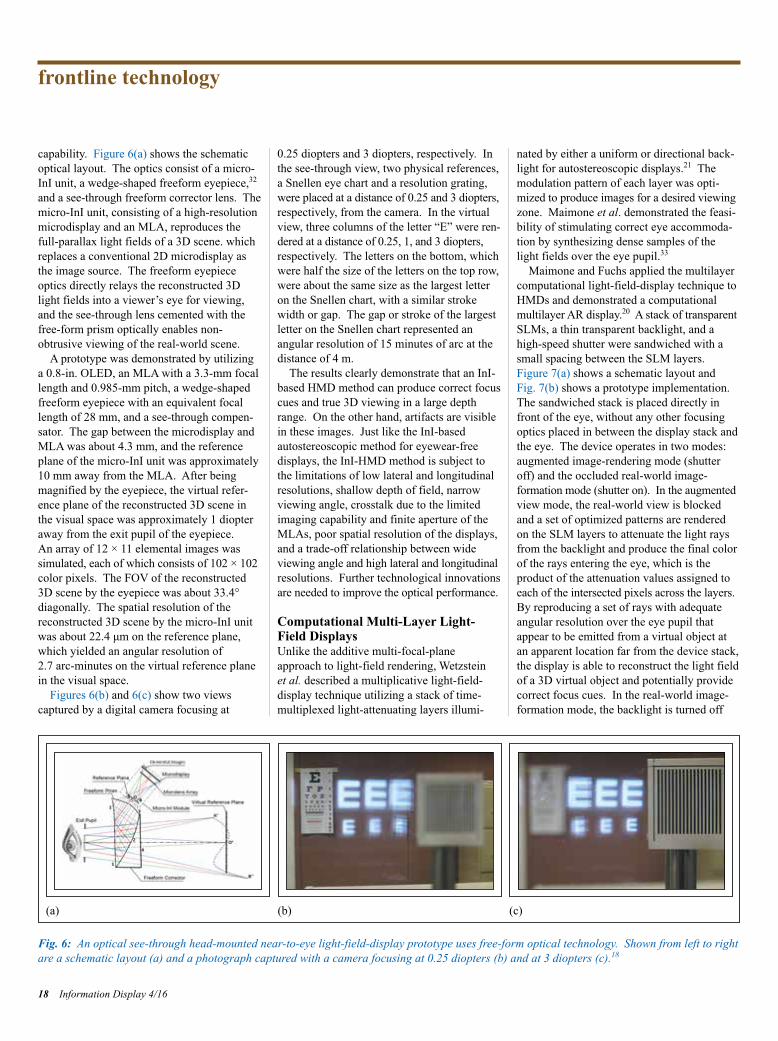
capability. Figure 6(a) shows the schematicoptical layout. The optics consist of a micro-InI unit, a wedge-shaped freeform eyepiece,32
and a see-through freeform corrector lens. The micro-InI unit, consisting of a high-resolutionmicrodisplay and an MLA, reproduces the full-parallax light fields of a 3D scene. whichreplaces a conventional 2D microdisplay asthe image source. The freeform eyepieceoptics directly relays the reconstructed 3Dlight fields into a viewer’s eye for viewing,and the see-through lens cemented with thefree-form prism optically enables non-obtrusive viewing of the real-world scene.
A prototype was demonstrated by utilizinga 0.8-in. OLED, an MLA with a 3.3-mm focallength and 0.985-mm pitch, a wedge-shapedfreeform eyepiece with an equivalent focallength of 28 mm, and a see-through compen-sator. The gap between the microdisplay andMLA was about 4.3 mm, and the referenceplane of the micro-InI unit was approximately10 mm away from the MLA. After beingmagnified by the eyepiece, the virtual refer-ence plane of the reconstructed 3D scene inthe visual space was approximately 1 diopteraway from the exit pupil of the eyepiece. An array of 12 × 11 elemental images wassimulated, each of which consists of 102 × 102color pixels. The FOV of the reconstructed3D scene by the eyepiece was about 33.4°diagonally. The spatial resolution of thereconstructed 3D scene by the micro-InI unitwas about 22.4 μm on the reference plane,which yielded an angular resolution of 2.7 arc-minutes on the virtual reference planein the visual space.
Figures 6(b) and 6(c) show two views captured by a digital camera focusing at
0.25 diopters and 3 diopters, respectively. Inthe see-through view, two physical references,a Snellen eye chart and a resolution grating,were placed at a distance of 0.25 and 3 diopters,respectively, from the camera. In the virtualview, three columns of the letter “E” were ren-dered at a distance of 0.25, 1, and 3 diopters,respectively. The letters on the bottom, whichwere half the size of the letters on the top row,were about the same size as the largest letteron the Snellen chart, with a similar strokewidth or gap. The gap or stroke of the largestletter on the Snellen chart represented anangular resolution of 15 minutes of arc at thedistance of 4 m.
The results clearly demonstrate that an InI-based HMD method can produce correct focuscues and true 3D viewing in a large depthrange. On the other hand, artifacts are visiblein these images. Just like the InI-basedautostereoscopic method for eyewear-free displays, the InI-HMD method is subject tothe limitations of low lateral and longitudinalresolutions, shallow depth of field, narrowviewing angle, crosstalk due to the limitedimaging capability and finite aperture of theMLAs, poor spatial resolution of the displays,and a trade-off relationship between wideviewing angle and high lateral and longitudinalresolutions. Further technological innovationsare needed to improve the optical performance.
Computational Multi-Layer Light-Field DisplaysUnlike the additive multi-focal-planeapproach to light-field rendering, Wetzstein et al. described a multiplicative light-field-display technique utilizing a stack of time-multiplexed light-attenuating layers illumi-
nated by either a uniform or directional back-light for autostereoscopic displays.21 Themodulation pattern of each layer was opti-mized to produce images for a desired viewingzone. Maimone et al. demonstrated the feasi-bility of stimulating correct eye accommoda-tion by synthesizing dense samples of thelight fields over the eye pupil.33
Maimone and Fuchs applied the multilayercomputational light-field-display technique toHMDs and demonstrated a computationalmultilayer AR display.20 A stack of transparentSLMs, a thin transparent backlight, and ahigh-speed shutter were sandwiched with asmall spacing between the SLM layers. Figure 7(a) shows a schematic layout and Fig. 7(b) shows a prototype implementation.The sandwiched stack is placed directly infront of the eye, without any other focusingoptics placed in between the display stack andthe eye. The device operates in two modes:augmented image-rendering mode (shutteroff) and the occluded real-world image-formation mode (shutter on). In the augmentedview mode, the real-world view is blockedand a set of optimized patterns are renderedon the SLM layers to attenuate the light raysfrom the backlight and produce the final colorof the rays entering the eye, which is the product of the attenuation values assigned toeach of the intersected pixels across the layers.By reproducing a set of rays with adequateangular resolution over the eye pupil thatappear to be emitted from a virtual object atan apparent location far from the device stack,the display is able to reconstruct the light fieldof a 3D virtual object and potentially providecorrect focus cues. In the real-world image-formation mode, the backlight is turned off
frontline technology
18 Information Display 4/16
Fig. 6: An optical see-through head-mounted near-to-eye light-field-display prototype uses free-form optical technology. Shown from left to rightare a schematic layout (a) and a photograph captured with a camera focusing at 0.25 diopters (b) and at 3 diopters (c).18
(a) (b) (c)
ID Hua p14-21_Layout 1 7/10/2016 6:21 PM Page 18

and the shutter is turned off. Occlusion maskscan be displayed on the SLM layers to allowselective transmission of the real-world rays,enabling mutual occlusion between virtualand real-world scenes.
Due to the close proximity of the SLMstack to the eye, this method could potentiallyachieve a compact OST-HMD with a wideFOV. Because of the light field’s rendering
nature, it can also potentially render correctfocus cues and mutual occlusion capabilities.The researchers’ early prototype demonstratedthese capabilities to some extent. On theother hand, the limitations of this approach arealso obvious and require significant innova-tions to enable improvements. For instance,both the rendered augmented views, althoughrecognizable, suffer dramatic resolution loss
due to diffraction effects through the SLMstack. The see-through view of the real worldis blurry and low in contrast due to the dif-fraction effects of the SLMs as well as thepartial transparency of the backlight. Thetechnique is computationally intensive, whichrequires significant effort to reduce the opti-mization time to enable real-time use for ARdisplays. Finally, the prototype also suffers
Information Display 4/16 19
Fig. 7: A computational multi-layer optical see-through light-field display: (a) a schematic layout and (b) prototype implementation.20
(a) (b)
(a) (b)
Fig. 8: A computational multi-layer light-field stereoscope appears in (a) the schematic layout and (b) prototype implementation.34
ID Hua p14-21_Layout 1 7/10/2016 6:21 PM Page 19
from high light loss due to the low transmit-tance of the SLM stack.
More recently, Wetzstein et al. extendedtheir multi-layer factored light-fieldautostereoscopic display method and demon-strated a light-field stereoscope for immersiveVR applications.34 The schematic layout andthe prototype implementation are shown inFigs. 8(a) and 8(b), respectively. The proto-type consists of two stacked LCD panels witha gap of 53 cm in between and a pair of simple magnifier lenses with a focal length of5 cm for each eye. Modulation patterns arecomputed using a rank-1 light-field factoriza-tion process to synthesize and render the lightfield of a 3D scene. Although their prelimi-nary demonstration is promising, thisapproach is subject to a diffraction limit dueto the fact that the virtual image pattern on therear display panel is observed through thefront panel.
Commercial Light-Field HMDs AreStill in the FutureClearly, as outlined in this article, recentprogress has been made in the development of head-mounted light-field displays for augmented- and virtual-reality applications.Despite the tremendous progress in pastdecades, all of the existing technicalapproaches are subject to different tradeoffsand limitations. The MFP display method iscapable of rendering correct focus cues for a3D scene across a large depth volume at highspatial resolution comparable to conventionalnon-light-field HMD methods, but it has toovercome several critical obstacles to becomea compact wearable-display solution. Themicro-InI-based light-field-display approachis able to render correct focus cues for a largedepth volume, but its optical performances,including spatial resolution, depth of field,longitudinal resolution, and angular resolu-tion, are relatively low compared to the MFPapproach. The computational multi-layerapproach is still in its preliminary develop-ment stage and requires significant innova-tions to overcome some fundamentallimitations such as diffraction artifacts.
We still have a long way to go to engineerhead-mounted displays with compact andportable form factors and high optical per-formance. However, based on the recent paceof development, I am confident that substan-tial progress and breakthroughs will be madeover the next 5 years, making possible the
commercial launch of head-mounted light-field displays for consumer applications.
AcknowledgmentsPart of the work reviewed is funded byNational Science Foundation Grant Awards0915035 and 1422653. Materials in thisreview article are partially based on co-authored papers and the Ph.D. dissertationwork on the development of multi-focal-planedisplays by Dr. Sheng Liu and Dr. Xinda Huwho were former graduate students affiliatedwith the 3D Visualization and Imaging Systems Laboratory at the University of Arizona. I would also like to acknowledgethe collaborative work on the integral-imag-ing-based display method with Prof. BahramJavidi at the University of Connecticut andthank Dr. Doug Lanman, Dr. David Luebke, Prof. Henry Fuchs, and Prof. Gordon Wetzstein for giving me the permission to usethe figures in their publications. Finally, Iwould like to acknowledge Dr. Nikhil Balramfor his generous help in editing the article.
References1R. Azuma, Y. Baillot, R. Behringer, S. Feiner, S. Julier, and B. Macintyre, “Recentadvances in augmented reality,” IEEE Computer Graphics and Applications 21(6),34–47 (2001).2S. Feiner, “Augmented reality: A new way ofseeing,” Scientific American 54 (2002).3http://www.google.com/glass/start/ 4http://www.epson.com/cgi-bin/Store/jsp/ Moverio/Home.do 5http://www.microsoft.com/microsoft-hololens/en-us6J. P. Wann, S. Rushton, and M. Mon-Williams, “Natural Problems for StereoscopicDepth Perception in Virtual Environments,”Vision Research 35(19), 2731–2736, (1995).7T. Inoue and H. Ohzu, “AccommodativeResponses to Stereoscopic Three-DimensionalDisplay,” Applied Optics 36(19), 4509–4515(1997).8D. M. Hoffman, A. R. Girshick, K. Akeley,and M. S. Banks, “Vergence-AccommodationConflicts Hinder Visual Performance andCause Visual Fatigue,” J. Vision 8(3), 1-30(2008).9S. J. Watt, K. Akeley, M. O. Ernst, and M. S. Banks, “Focus Cues Affect PerceivedDepth,” J. Vision 5(10), 834–862 (2005).10S. Shiwa, K. Omura, and F. Kishino, “Proposal for a 3-D display with accommoda-
tive compensation: 3DDAC,” J. Soc. Info.Display 4(4), 255–261, (1996).11S. Liu, H. Hua, and D. Cheng, “A novel prototype for an optical see-through head-mounted display with addressable focuscues,” IEEE Trans. Vis. Comput. Graph. 16,381–393 (2010).12J. P. Rolland, M. Kureger, and A. Goon,“Multifocal planes head-mounted displays,”Applied Optics 39(19), 3209–3214 (2000).13K. Akeley, S. J. Watt, A. R. Girshick, andM. S. Banks, “A Stereo Display Prototypewith Multiple Focal Distances,” ACM Trans.Graph. 23, 804–813 (2004).14S. C. McQuaide, E. J. Seibel, J. P. Kelly, B. T. Schowengerdt, and T. A. Furness, “Aretinal scanning display system that producesmultiple focal planes with a deformable mem-brane mirror,” Displays 24(2), 65–72, (2003).15S. Liu and H. Hua, “Time-multiplexed dual-focal-plane head-mounted display with a fastliquid lens,” Optics Letter 34(11), 1642–4164(2009).16G. D. Love, D. M. Hoffman, P. J. W. Hands,J. Gao, A. K. Kirby, and M. S. Banks, “High-speed switchable lens enables the develop-ment of a volumetric stereoscopic display,”Opt. Express 17(18), 15716–15725 (2009).17S. Liu and H. Hua, “A systematic methodfor designing depth-fused multi-focal planethree-dimensional displays,” Opt. Express18(11), 11562–11573 (2010).18H. Hua and B. Javidi, “A 3D integral imaging optical see-through head-mounteddisplay,“ Optics Express 22(11), 13484–13491(2014).19D. Lanman and D. Luebke, “Near-eye lightfield displays, “ Proc. ACM SIGGRAPH(ACM Transaction on Graphics) (2013).20A. Malmone, and H. Fuchs, “Computationalaugmented reality eyeglasses,” Proc. ISMAR,29–38, (2013).21G. Wetzstein, D. Lanman, M. Hirsch, and R. Raskar, “Tensor Displays: Compressivelight field synthesis using multilayer displayswith directional backlighting,” Proc. ACMSIGGRAPH (ACM Transaction on Graphics)(2012).22B. T. Schowengerdt, M. Murari, and E. J. Seibel, “Volumetric display using scanned fiber array,” SID Symp. Digest of Tech. Papers (2010).23W. Wu, I. Tosic, N. Bedard, P. Llull, K. Berkner, and N. Balram, “Near-eye displayof light fields, presented at IDW 2015.24S. Suyama, S. Ohtsuka, H. Takada, K. Uehira, and S. Sakai, “Apparent 3-D image
frontline technology
20 Information Display 4/16
ID Hua p14-21_Layout 1 7/10/2016 6:21 PM Page 20
perceived from luminance-modulated two 2-Dimages displayed at different depths,” VisionRes. 44(8), 785–793 (2004). 25X. Hu and H. Hua, “Design and Assessmentof a Depth-Fused Multi-Focal-Plane DisplayPrototype,” Disp. Technol. J., 1 (2014).26X. Hu, Development of the Depth-FusedMulti-Focal-Plane Display Technology, Ph.D.Dissertation, College of Optical Sciences,University of Arizona (2014).27X. Hu and H. Hua, “High-resolution opticalsee-through multi-focal-plane head-mounteddisplay using freeform optics,” Optics Express22(11), 13896–13903 (2014).28X. Hu and H. Hua, “Distinguished StudentPaper: A Depth-Fused Multi-Focal-Plane Display Prototype Enabling Focus Cues inStereoscopic Displays,” SID SymposiumDigest of Technical Papers 42, paper 48.1,691–694 (2011).29S. Ravikumar, K. Akeley, and M. S. Banks,“Creating effective focus cues in multi-plane3D displays,” Opt. Express 19, 20940–20952(2011).30G. M. Lippmann, “Epreuves ReversiblesDonnant la Sensation du Relief,” J. Phys. 7,4th series, 821–825 (1908).31J. Hong, S. Min, and B. Lee, “Integral float-ing display systems for augmented reality,”Applied Optics 51(18), 4201–4209 (2012).32D. Cheng, Y. Wang, H. Hua, and M. M.Talha, “Design of an optical see-throughhead-mounted display with a low f-numberand large field of view using a freeformprism,” Appl. Opt. 48, 2655–2668 (2009).33A. Maimone, G. Wetzstein, M. Hirsch, D. Lanman, R. Raskar, and H. Fuchs, “Focus3D: compressive accommodation display,”ACM Trans. Graphics 32(5), 153:1–153:3(2013).34F. Huang, K. Chen, and G. Wetzstein. “TheLight Field Stereoscope: Immersive ComputerGraphics via Factored Near-Eye Light FieldDisplays with Focus Cues,” ACM SIGGRAPH(Transactions on Graphics), 33(5) (2015). n
Information Display 4/16 21
Information Display welcomescontributions that containunique technical, manufactur-ing, or market research contentthat will interest and/or assistour readers – individuals
involved in the business or research of displays.
Please contact Jenny Donelan, Managing Editor,at [email protected] withquestions or proposals.
Turn to page 41 for a list of2016 editorial themes, withapproximate dates for submitting article proposals.
InformationDISPLAY
SIDSOCIETY FOR INFORMATION DISPLAY
DISPLAY WEEK 2015 REVIEW AND METROLOGY ISSUE
Official Publication of the Society for Information Display • www.informationdisplay.org
Sept./Oct. 2015
Vol. 31, No. 5
IMAGING TECHNOLOGIES AND LIGHTING ISSUE
Official Monthly Publication of the Society for Information Display • www.informationdisplay.org Nov./Dec. 2015Vol. 31, No. 6
Display Week 2017SID International Symposium, Seminar & Exhibition
May 21–26, 2017Los Angeles Convention Center,
Los Angeles, CA, USA
Submit Your News ReleasesPlease send all press releases and new product announcements to:
Jenny DonelanInformation Display Magazine
411 Lafayette Street, Suite 201, New York, NY 10003Fax: 212.460.5460 e-mail: [email protected]
ID Hua p14-21_Layout 1 7/10/2016 6:21 PM Page 21

WE all know we should devote moretime to learning about our industry, but theday-to-day demands of our jobs make it diffi-cult to focus outside our respective academicor industrial silos. The SID Bay Area chapter(BA-SID), in collaboration with sponsor Honeywell, recently addressed this “education gap” with a fast-paced (16 speakers in 9 hours), one-day ( March 24, 2016) conferencedesigned to shed light on a wide range oftechnical and non-technical topics related tothe display industry. These included theexpected – OLEDs, QLEDs, and e-Paper –and the less expected – microdisplays and thebrain, display data management, and changesin traditional environments for innovation.
“The thing I really liked about the confer-ence is that it exposed me to such a wide variety of things I don’t normally think muchabout,” said Oregon State University’s JohnWager, who gave a presentation about back-planes. “I tend to stay in my very narrowfield of specialized focus.” The diversity of topics, including history, technology, markets, manufacturing, aerospace, businesstrends, data management, systems, and products,made it different from the ultra-specializedsessions he usually attends, added Wager.
For example: “I thought the Dolby presen-tation was amazing,” he said. “Dolby doessomething other than sound. Who knew? The MIT Media Lab embedded interactivitywas completely new to me and very interest-ing. And the resonant-frequency presentation[haptics] demonstrated to me that very clever
and useful things can be accomplished usingvery simple ideas.”
Market analyst Paul Semenza, who deliv-ered the afternoon keynote, said, “The BayArea SID conference provided examples ofcompanies pursuing approaches that areaimed at differentiation and efficient produc-tion.” These approaches are going to becomeincreasingly important, he explained, as the
hyper-competitive flat-panel-display industrycontinues to be dominated by increasinglyhigh performance but otherwise undifferenti-ated products.
One example of this type of targetedapproach came from speaker John Ho of QDVision, who described the implications of theRec.2020 standard for display development.While pixel densities are reaching the limits
One Day, Sixteen Speakers, InnumerableInsightsThe Bay Area chapter of SID recently brought together 16 experts for a fascinating, far-ranging look at issues that are shaping the display industry.
by Jenny Donelan, Sri Peruvemba, Paul Semenza, and John Wager
22 Information Display 4/160362-0972/4/2016-022$1.00 + .00 © SID 2016
Inventor Frederic Kahn, who has worked many years in the display business, explained howLCDs began fundamentally changing the display industry in the late 1960s.
conference review
ID Donelan p22-24_Layout 1 7/10/2016 6:12 PM Page 22

of the human visual system, the ability to display colors is relatively limited on mostdisplays, and Rec.2020 specifies a broadercolor-gamut target than (for example) theNTSC standard.
A second example is flexible displays, alongstanding goal for the display industry.The ongoing development of curved OLEDdisplays for smartphones and wearables repre-sents progress toward this goal. However,these displays generally require the TFTs to be produced on glass substrates and thentransferred to plastic because the processingtemperature for the silicon devices is too highfor plastic. The requirement of glass for TFTfabrication also means that inherently flexible-display technologies such as EPD are gener-ally produced on rigid substrates. But asFlexEnable’s Mike Banach described at thisconference, his company has been developingorganic TFTs that can be produced on plastic.Working with Merck, FlexEnable has beenable to demonstrate plastic TFT-LCDs that are not only thinner and lighter than glass-based LCDs, but are flexible to a bend radiusof 35 mm. FlexEnable has also demonstratedthe ability to drive OLEDs with its organicTFTs.
“The display industry is hyper-competitiveand driven by increasingly large investments – as currently exemplified by the multi-billion-dollar sums going into building OLED capacity,” said Semenza. Despite the current phenomenon of new technologies being over-looked in favor of standardized TFT-LCD and OLED displays (which have already beenheavily invested in), the above examples indicate that the display industry still harborsinnovative approaches, he noted.
A Day of Display TechnologyDr. Russ Gruhlke, Chair of the BA-SID; Dr. Sudip Mukhopadhyay, Honeywell Fellow;and Sri Peruvemba, Director of the Bay Areachapter, kicked off the event with a welcomeaddress and an introduction of the speakers.Short descriptions of these speakers and theirtopics follow:Morning Keynote: “The Past, Present, and
Future of LCDs – The Black Swan Maturesand Prospers,” by Dr. Frederic J. Kahn, President, Kahn International.
Kahn, an inventor, company founder, SIDboard member, editor, and recipient of someof SID’s highest honors, described the BlackSwan as a high-impact event that is hard to
predict, similar to the LCD in 1967. (Somemight also refer to this as disruptive technol-ogy.) Kahn traced the history of LCD devel-opment along with his own 49 years ofexperience, which included his invention ofthe vertically aligned nematic LCD still in use today.“Flat-Panel Display Backplanes: Past,
Present, and a Possible Future Option,”by Dr. John Wager, Chair, School of EECS,Oregon State University.
Wager discussed a-Si products used in thepast, the current crop of a-Si:H LTPS andIGZO technologies, and the possibilities ofamorphous-metal non-linear resistors(AMNRs).“OLED and QLED,” by Professor Poopathy
Kathirgamanathan, Chair, Electronic MaterialsEngineering, Brunel University, UK.
The focus of Kathirgamanathan’s presenta-tion was OLED and QLED devices, as well asthe merits of quantum materials in achievingRec.2020 specifications.“Avionic Display Systems,” by Dr. Kalluri
Sarma, Senior Fellow, Honeywell.Cockpit applications have specific display
needs. Sarma described the work done by histeam on the Boeing 777, the F16 fighter plane,various military and commercial planes, andthe space station.“Challenges and Opportunities in Display
Data Management,” by Dr. Wei Xiong, Vice-President, Samsung Display.
The display interface is highly important,but often overlooked, noted Xiong. While display resolution has increased significantly,panel interfaces have not. Data transmissionvia wires in the display has not kept up withpixel resolution, and Xiong expects tremen-dous demand in this area. “Advances in Video,” by Ajit Ninan,”
Vice-President, Dolby.Humans can see a lot more dynamic range
in color and luminance levels than what current displays offer, according to Ninan.We want 200x more brightness and 4000xmore contrast. He talked about movie makers’desire to create more accurate renditions oftheir carefully orchestrated scenes, includingmore immersive colors and full dynamicrange. Work in this area by Dolby has wonthe company both Emmy and Oscar awards.“Beyond the Touch Screen: Embedded
Interactivity for a Naturally Intelligent Envi-ronment,” by Dr. Munehiko Sato, Scientist,MIT Media Lab & University of Tokyo.
Sato’s research team has created interactivesurfaces in everyday objects such as doorknobs. Using bio impedance, his team haseven been able to make plants touch-interactive.The team has built interfaces into chairs thatcan recognize individual users and accord-ingly create a custom environment for eachoccupant. Afternoon Keynote: “Display Technology
and Market Overview,” by Paul Semenza,Director of Commercialization, NextFlex.
Semenza traced the history of display technologies and offered a panel roadmap,describing the “race to the bottom” with thecreation of larger fabs and lower priced products.There has not been any killer app for displayconsumption since the tablet, and the newerapps in vehicles, wearables, etc., use muchless display by area. The industry is in adown cycle and there has been a culling ofplayers and technologies. Hardly any Japan-ese players remain. Taiwan is not investingdomestically; Korea has augmented verticalintegration with a China strategy; and Chinacontinues to catch up. Materials and equip-ment companies are profitable, whereas panelmakers continue to struggle.“Haptics; It’s All about Resonant
Frequency,” by Francois Jeanneau, CEO,Novasentis.
Jeanneau’s talk about haptic technologyidentified the need for richer interactions. Thecurrent crop of products in the market usingeccentric rotating mass (ERM) and linear resonant actuator (LRA) technologies leaves agap in customer expectations. Newer tech-nologies such as electromechanical polymers(EMPs) offer a range of pleasing sensations,are thin as paper, and enable new form fac-tors. One smartphone has replaced some $3Kworth of other electronic devices. As thesmartphone continues to evolve, will it trans-form itself to a wearable device by 2020 andwhat will it look like? What are the enablingtechnologies?“The Path to Rec.2020 Displays: Quantum
Dots Versus Frickin’ Lasers,” by John Ho,Product Marketing Manager, QD Vision.
Display resolution is increasing, althougheventually we will not be able to discern it.But there is lots of room for improvement incolor. Lasers can achieve desired color specsbut they are not practical – they are cost-prohibitive and susceptible to observermetameric failure (OMF), in which two view-ers see the same source of light and perceive
Information Display 4/16 23
ID Donelan p22-24_Layout 1 7/10/2016 6:12 PM Page 23
different hues. Quantum-dot technology offers the best path to achieving Rec.2020 spec. It is less expensive, and tunable primaries can reduce OMF and are easier to create through leverag-ing existing LCD fabs. Quantum dots do facechallenges, including regulatory barriers dueto the use of heavy metals such as cadmium.“Flex Display Manufacturing,” by Mike
Banach, Technical Director, FlexEnable.Banach’s talk focused on organic-TFT-
backplane LCDs (OLCDs), which enable flexible devices. His team has built devicesusing a number of frontplanes includingOLED displays and e-Paper, but he believesthat flexible-LCD technology offers a viablepath forward through leveraging the existinginfrastructure. He cited favorable trends forflexible displays, including the emergingInternet of Things and wearables markets,which are creating a desire for rollable,curved, and foldable devices.“Flexible Transparent Barrier Films,” by
Dr. Ravi Prasad, Chief Technology Officer,Vitriflex.
Flexible transparent barrier films are beingmade by a roll-to-roll process for a variety ofapplications, including displays. Barrier filmsplay a crucial role in the development ofnewer display technologies, including flexibledisplays and quantum dots. The goal is to createa film that has glass-like optical properties butis thinner, lighter, and unbreakable. Prasad’steam has made great progress in addressingchanging market needs through this technology.“Delivering on the Promise of e-Paper,”
by Luka Birsa, CTO, Visionect.Birsa has been working on e-Paper devices
for 8 years, and his team has been able to deploy them in a variety of applications, includingstreet signs in Sydney, Australia, on buses andat bus stops in Europe, and as conferenceroom signs and e-Labels in museums andretail stores. He emphasized the value of low-power signage products that allow for the useof solar panels to power them in existinginfrastructures without the need for digging orwiring power lines. In outdoor applications,the e-Paper’s sunlight readability is a greatenabler. Birsa’s company has won numerousawards, including a CES Innovation award,for its conference-room signage.
“Sensors Integrated in Displays,” byDr. Guillaume Chansin, Senior TechnologyAnalyst, IDTechEx.
Chansin’s work comprises OLEDs, flexiblesensors, and quantum dots. He began his
presentation with the premise that a displaytends to be a large part of most devices, sowhy not use it as the platform for sensors?These could be light sensors, motion sensors,touch sensors, etc. The trends he foresees inthe market include the ability to embed sensors in displays, allowing for automaticadjustments to light and proximity sensing forinteraction with objects and humans, bio-metric sensing, etc.“Microdisplays and Interfacing with the
Brain,” by Mina Hanna, Ph.D. student, Stanford University.
Hanna explained some of the work goingon in academia relating to microdisplays inbrain stimulation; they offer great potential for treating brain-related illnesses such asParkinson’s disease. His team is working onmicrowire bundles that allow cellular- and circuit-level targeting; microdisplays allowthem to control individual microwires.Evening Keynote: “Mapping the U.S.
Innovation System Today,” by Professor FredBlock, UC Davis.
Block observed that the decline of largecorporate labs in the past three decades, withmany Ph.D.s moving to smaller firms, has ledtoward the trend of government-university-industry (GUI) collaboration. The currentenvironment has its flaws – managing andcoordinating is a big hurdle, the IP system canbe dysfunctional, small firms are ignored byventure capitalists, and innovators have tobuild complex political alliances to scale. Hecalled for more public awareness of thischanged environment and highlighted theneed for new rules and methods so as toencourage more innovators.
Beyond the Comfort ZoneOver 100 Bay Area display-industry enthusi-asts attended this information-filled event inSunnyvale. The evening reception allowedspeakers and attendees to mingle – many continued informal discussions late into theevening. This knowledge transfer event, inwhich many of the speakers shared their life’swork in a few minutes, will be held again.“The BA-SID was super excited by how theevent turned out and plans to repeat this witha much larger audience next year,” said SriPeruvemba, one of the organizers.
AcknowledgmentsThe BA-SID wishes to thank Honeywell forsponsoring the event. Members of the team
that helped make it a success include: AnnaCamarena, Lance Chapman, Scott Hanson,Sudip Mukhopadhyay, and Mark Cyffka fromHoneywell and BA-SID officers includingBryan Chan, Neetu Chopra, Calvin D’Souza,Russ Gruhlke, Jagadish Kumaran, JohnMiller, Sri Peruvemba, Vignesh Sanmugam,and Xuena Zhang. n
conference review
24 Information Display 4/16
VISITINFORMATION
DISPLAY ON-LINEwww.informationdisplay.org
J O I N S I DWe invite you to join SID to participate in shaping the future development of:
• Display technologies and display-related products
• Materials and components for displays and display applications
• Manufacturing processes and equipment
• New markets and applications
In every specialty you will find SIDmembers as leading contributors totheir profession.
http://www.sid.org/Membership.aspx
ID Donelan p22-24_Layout 1 7/10/2016 6:12 PM Page 24

Meet With Leading Companies Like These
THE EXHIBITION: Here you’ll experience hands-on demos, source, collaborate and conduct problem solving with expert tech reps from dozens of leading display technology product, service and solution providers.
Exhibitors & Sponsors: Email Alicia Waldron [email protected] or call (212) 460-8090 ext. 216
THE SYMPOSIUM: Here you’ll hear peer-reviewed technical presentations from the industry’s brightest and stay current on new technologies and breakthroughs. Get your first-look at next generation tech ‘magic’ destined to shape tomorrow’s holistic in-car experiences and car buyer preferences in the promising and growing trillion-dollar global automotive marketplace.
You’re invited to attend the 23rd annual SID Vehicle Displays Symposium & Expo Detroit, September 27-28, 2016, presented by the Detroit Chapter of the Society for Information Display in the center of U.S. automotive excellence. It’s too important to miss.
DETROIT’S ONLY SYMPOSIUM & EXPO FOR THE DISPLAY, HMI, VEHICLE SYSTEMS, PHOTONICS, AND AUTO OEM COMMUNITIES
THE TECHNO-FUTURE OF THE IN-CARDRIVING EXPERIENCE STARTS HERE.

THE color gamut defines the palette ofavailable colors that a display can produce –so it is the most important defining visualcharacteristic of any display. While colorgamuts have changed over the years, in thepast, virtually all displays needed just a singlegamut to produce all of the content that a userwanted to see. But with the recent develop-ment of several wider-color-gamut standardsfor producing new content, including DCI-P3 for 4K UHD TVs and digital cinema, all future TVs, monitors, smartphones, tablets, and laptops will need to support at least two color gamuts.
So, there is a big learning curve for consumers, reviewers, content producers, andeven manufacturers with regard to the properuse of the new color gamuts. In this article,we will examine and compare some of themost important display color gamuts that havebeen appearing in consumer products over thelast 60-plus years, from the earliest NTSCgamut up through the latest DCI-P3 andRec.2020 gamuts. In short, gamuts have beenevolving and getting progressively larger.
Display Color Gamuts and StandardsOver the years, there have been an incrediblywide range of color gamuts that have beenimplemented for displays. Many are simplybased on the particular native primary colors
conveniently available at the time at low costfor different display technologies such asCRT, plasma, LCD, OLED, LED, quantumdots, phosphors, lasers, etc. Many applica-tions just need any suitable range of colors tosatisfy a user’s needs. However, essentiallyall imaging-based applications need a specificwell-defined color gamut in order to accuratelyreproduce the colors in the image content.Over the years, this has given rise to manydifferent standard color gamuts for image content, and they have generally been basedon what the current displays at the time couldproduce. So both the displays and contenthave evolved together over time, and manydifferent gamuts have been defined, but theyhave not all been created equal.
What makes a color gamut important and atrue standard is the existence of lots of contentcreated specifically for that gamut: manufac-turers then need to include that standard intheir products. So, it is the content and content producers that define a true color-gamut standard – the displays then need todeliver it as accurately as possible on-screen.Every display needs to adapt its native colorgamut for the content that it has to show. This is implemented using color management,which we discuss below.
While people primarily think of colorgamuts in terms of their outermost saturatedcolors, most image content is generally foundin the interior regions of the gamut, so it isparticularly important that all of the interiorless-saturated colors within the gamut beaccurately reproduced.
And if you are not sure of the set of colorsthat the different gamuts actually produce, wewill show you accurately colorized versions ofthe two most important standard gamuts beingused today so you can evaluate them visually.In case you think you have already seen colorized gamuts before, the colors shown inessentially all published color gamuts are fictitious and wildly incorrect. We have accurately calculated them here.
Color Gamuts and Ambient LightOne very important point that applies to alldisplays is the color gamut that you actuallysee on-screen is reduced by any existingambient light falling on the screen. Since veryfew users watch their displays in absolute dark-ness (0 lux), the color gamut that is actuallyseen is noticeably less than 100%. We exam-ined this very important effect and its solutionin an online DisplayMate article in 2014.1
NTSC Color GamutThe first official color gamut standard for displays was the NTSC color gamut, whichmade its debut in 1953 for the beginning ofU.S. color-television broadcasting. However,the NTSC primary colors were too saturatedand could not be made bright enough for usein the consumer (CRT) TVs of that era, so theNTSC color gamut was never actually imple-mented for volume commercial production ofcolor TVs. As a result, the NTSC gamut wasnever an actual standard color gamut, andthere is essentially no consumer content basedon the true NTSC color gamut. This is amus-
Display Color Gamuts: NTSC to Rec.2020Modern color gamuts are one of the most misunderstood aspects of display metrology. Here, we will examine the usefulness of the still widely referenced 1953 NTSC gamut and also compare accurately colorized gamuts in the 1931 and 1976 CIE color spaces.
by Raymond M. Soneira
Raymond M. Soneira is the founder andPresident of DisplayMate Technologies Corporation. This article is based on originalcontent from www.displaymate.com. He canbe reached at [email protected].
26 Information Display 4/160362-0972/4/2016-026$1.00 + .00 © SID 2016
frontline technology
ID Soneira p26-31_Layout 1 7/10/2016 6:37 PM Page 26
ing (and annoying) because now, more than60 years later, many manufacturers andreviewers are still quoting and referring to the NTSC gamut as if it were some sort ofstate-of-the-art standard, while in fact it hasbeen obsolete and colorimetrically disjointedfrom most other standard gamuts for anincredibly long time.
Manufacturers of high-tech display prod-ucts should be embarrassed for publishingtheir specifications in terms of NTSC, anobsolete technology more than 60 years old.So please everyone – let’s stop referring to thevery outdated NTSC and instead move on tothe actual color gamuts that are being used intoday’s displays.
The Real Analog-TV and Standard-Definition-TV Color GamutsInstead of the official NTSC gamut colors, thepractical phosphor colors that were actuallyused in early color TVs were developed by theConrac Corporation. The result became theSMPTE-C color-gamut standard. TV produc-tion studios used Conrac color monitors toproduce their broadcast TV content, so it wasthe Conrac color gamut rather than the NTSCgamut that was the real color-television stan-dard gamut. The SMPTE-C gamut is not thatdifferent from today’s sRGB/Rec.709 gamut,which is 13% larger than that of SMPTE-C.Many later gamut standards were based onSMPTE-C, including up to Rec.601 for Digital Standard-Definition TV. We are nowgoing to skip over lots of history and get tothe display color gamuts that are in use today.
sRGB/Rec.709 Color GamutFor over 10 years, the main color gamut thathas been used for producing virtually all current consumer content for digital cameras,HDTVs, the Internet, and computers, includ-ing photos, videos, and movies, is a dual standard called sRGB/Rec.709. If you wantto see accurate colors for this content on justabout any consumer product, then the displayneeds to match the sRGB/Rec.709 standardcolor gamut – not larger and not smaller. Ifyour display does not faithfully render thecontent in this gamut, the colors will appearwrong and also be either too saturated orunder-saturated.
There are still widely held beliefs by manyreviewers and consumers that viewing contenton a display with a larger color gamut is actu-ally better, but it is definitely worse because
the display will produce colors that were notactually present in the original content, creat-ing an oversaturated or generally incorrectrendering. Below, in Figs. 1–4, we will showboth visually and quantitatively what thesRGB/Rec.709 color gamut looks like in boththe 1976 and 1931 CIE diagrams.
Accurately Matching the Color-GamutStandardFor reasons similar to what occurred long agowith the NTSC gamut, up until recently a reasonable fraction of all displays could notproduce 100% of the sRGB/Rec.709 colorgamut. This was especially true for mobiledisplays, which in many cases provided lessthan 70% of the sRGB/Rec.709 gamut due toluminance and efficiency issues similar tothose that had plagued the NTSC gamut. As aresult, their on-screen images appeared some-what bland and under-saturated. But today,most good-quality products have displays thatproduce close to 100% of the sRGB/Rec.709color gamut.
Similar issues also apply to the newest andlargest color gamuts, DCI-P3 and Rec.2020,which we examine in detail below. 4K UHDTVs only need to provide 90% of the DCI-P3color-gamut standard to receive a 4K UHDAlliance certification, and the currently avail-able Rec.2020 displays typically only provide90% of the Rec.2020 color-gamut standard. It has always taken some time for displays tofully and properly implement the latest color-gamut standards. However, this delay intro-duces color errors that reduce the absolutecolor accuracy of the displayed content, whichwe discuss below.
Adobe RGB Color GamutMost high-end digital cameras have an optionto use the standard Adobe RGB color gamut,which is 17% larger than the standardsRGB/Rec.709 color gamut that is used inconsumer cameras. The Adobe RGB gamut isalso used in many other advanced and profes-sional imaging applications. For consumers,Samsung’s Galaxy smartphone and Galaxytablet OLED displays accurately produce the Adobe RGB gamut as covered in DisplayMate’s Mobile Display Technology Shoot-Out articleseries.2
DCI-P3 Color GamutThe newest standard color gamut that has significant content is DCI-P3, which is 26%
larger than the sRGB/Rec.709 gamut. It isbeing used in 4K UHD TVs and in digital cinema for the movie industry, so while theamount of existing DCI-P3 content is still relatively small compared to that forsRGB/Rec.709, it is now starting to grow rapidly. DCI-P3 is also being adopted inmany other new displays and applications thatneed to provide a wider color gamut with a wider range of more saturated colors. DisplayMate recently tested the new AppleiPad Pro 9.7, which has a very accurate native100% DCI-P3 gamut and also produces a veryaccurate 100% sRGB/Rec.709 gamut by usingcolor management.3
Rec.2020 Color GamutThe next-generation standard color gamut willbe the impressively large Rec.2020 standard,shown in Fig. 1. In fact, it is 72% larger thanthe sRGB/Rec.709 and 37% larger than theDCI-P3. The color gamut is extremely wideand the color saturation extremely high.However, there is almost no current existingcontent for Rec.2020. And there are very fewexisting displays that come close to providingRec.2020, which requires quantum dots forLCDs. Of course, continuing progress isbeing made in extending the color gamuts for both LCD and OLED panels, so Rec.2020will become an important new standard gamut within the next several years.
Comparing the Standard ColorGamutsFigure 1 shows the color gamuts for most ofthe standards that we have been discussing.They are all plotted on a CIE 1976 uniformchromaticity (color) diagram that quantita-tively evaluates color in a perceptually uniform manner for human color vision with(u’,v’) color coordinates. All of the colorregions and visual differences among colorsremain consistent throughout the entire 1976CIE color space, so it provides an excellentand accurate method for specifying, manufac-turing, marketing, comparing, measuring, andcalibrating displays.
Note that the older 1931 CIE diagrams with(x,y) color coordinates that are published bymany manufacturers and reviewers are verynon-uniform and distorted, so they are effec-tively meaningless for quantitatively evaluat-ing color gamuts and their color accuracy.The color gamuts shown in Fig. 1 wouldappear very differently in the 1931 CIE
Information Display 4/16 27
ID Soneira p26-31_Layout 1 7/10/2016 6:37 PM Page 27
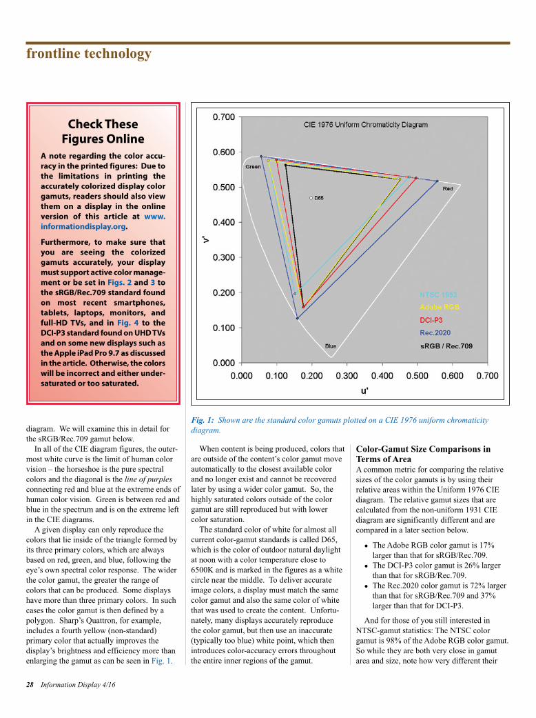
diagram. We will examine this in detail forthe sRGB/Rec.709 gamut below.
In all of the CIE diagram figures, the outer-most white curve is the limit of human colorvision – the horseshoe is the pure spectral colors and the diagonal is the line of purplesconnecting red and blue at the extreme ends ofhuman color vision. Green is between red andblue in the spectrum and is on the extreme leftin the CIE diagrams.
A given display can only reproduce the colors that lie inside of the triangle formed byits three primary colors, which are alwaysbased on red, green, and blue, following theeye’s own spectral color response. The widerthe color gamut, the greater the range of colors that can be produced. Some displayshave more than three primary colors. In suchcases the color gamut is then defined by apolygon. Sharp’s Quattron, for example,includes a fourth yellow (non-standard) primary color that actually improves the display’s brightness and efficiency more thanenlarging the gamut as can be seen in Fig. 1.
When content is being produced, colors thatare outside of the content’s color gamut moveautomatically to the closest available colorand no longer exist and cannot be recoveredlater by using a wider color gamut. So, thehighly saturated colors outside of the colorgamut are still reproduced but with lowercolor saturation.
The standard color of white for almost allcurrent color-gamut standards is called D65,which is the color of outdoor natural daylightat noon with a color temperature close to6500K and is marked in the figures as a whitecircle near the middle. To deliver accurateimage colors, a display must match the samecolor gamut and also the same color of whitethat was used to create the content. Unfortu-nately, many displays accurately reproducethe color gamut, but then use an inaccurate(typically too blue) white point, which thenintroduces color-accuracy errors throughoutthe entire inner regions of the gamut.
Color-Gamut Size Comparisons inTerms of AreaA common metric for comparing the relativesizes of the color gamuts is by using their relative areas within the Uniform 1976 CIEdiagram. The relative gamut sizes that arecalculated from the non-uniform 1931 CIEdiagram are significantly different and arecompared in a later section below.
● The Adobe RGB color gamut is 17%larger than that for sRGB/Rec.709.
● The DCI-P3 color gamut is 26% largerthan that for sRGB/Rec.709.
● The Rec.2020 color gamut is 72% largerthan that for sRGB/Rec.709 and 37%larger than that for DCI-P3.
And for those of you still interested inNTSC-gamut statistics: The NTSC colorgamut is 98% of the Adobe RGB color gamut.So while they are both very close in gamutarea and size, note how very different their
frontline technology
28 Information Display 4/16
Check These Figures Online
A note regarding the color accu-racy in the printed figures: Due tothe limitations in printing theaccurately colorized display colorgamuts, readers should also viewthem on a display in the online version of this article at www.informationdisplay.org.
Furthermore, to make sure thatyou are seeing the colorizedgamuts accurately, your displaymust support active color manage-ment or be set in Figs. 2 and 3 tothe sRGB/Rec.709 standard foundon most recent smartphones,tablets, laptops, monitors, andfull-HD TVs, and in Fig. 4 to theDCI-P3 standard found on UHD TVsand on some new displays such asthe Apple iPad Pro 9.7 as discussed in the article. Otherwise, the colors will be incorrect and either under-saturated or too saturated.
Fig. 1: Shown are the standard color gamuts plotted on a CIE 1976 uniform chromaticity diagram.
ID Soneira p26-31_Layout 1 7/10/2016 6:37 PM Page 28

triangular gamut shapes and color regions arein Fig. 1, proving that the still current practiceof using NTSC for gamut specifications, andcomparisons has little colorimetric meaning oruseful quantitative value for the currentgamuts and displays (and is doubly incorrectwhen combined with the non-uniform 1931CIE color space).
Accurately Colorized sRGB/Rec.709Color GamutFigures 2 and 3 show an accurately colorizedsRGB/Rec.709 color gamut. For displays thiscan only be done for a single color gamut at atime. The colors in the figure have been accurately calculated to show the real colorswithin the sRGB/Rec.709 gamut – the colorsshown in most published color gamuts are fictitious and wildly incorrect. Also includedare 41 reference colors that we use for measuring absolute color accuracy throughoutthe entire gamut, which is discussed below.
Note that printed versions of the colorizedgamuts depend on the particular inks beingused and also their spectral absorption of theparticular ambient light you are viewing themin, so they cannot be as accurate as whenviewed on an emissive display, and they alsogenerally provide smaller gamuts than mostdisplays. (See sidebar on previous page.)
Note that every color within the gamut isshown at its maximum brightness (lumi-nance). White is the brightest color near themiddle because it is the sum of the peak red, green, and blue primary colors. The secondary colors of cyan, magenta, and yellow radiatefrom the white point as ridges because theyare the sums of two primary colors.
One particularly interesting result seen inFig. 2 is how relatively small the green regionof the sRGB/Rec.709 color gamut is in theaccurate 1976 CIE uniform color space.However, the green region appears consider-ably larger in the distorted and non-uniform1931 CIE chromaticity diagram, as shown inFig. 3. The newer color gamuts – AdobeRGB, DCI-P3, and Rec.2020 – all signifi-cantly enlarge the green region of their colorspace within the uniform 1976 CIE diagram.
Absolute Color Accuracy and JustNoticeable Color Differences (JNCD)One very important issue is the accuracy ofeach display’s color gamuts, and the absolutecolor accuracy for all of the colors within theentire color gamut. One vital reason for accu-
rately colorizing and rendering each colorgamut in the 1976 CIE uniform color space isthat the display’s color accuracy and color calibration can be accurately analyzed uniformly, and then the true color errors uniformly minimized for all of the colorswithin the color gamut. The errors areexpressed in terms of Just Noticeable Color Differences (JNCD), which correspond tofixed linear distances within the CIE diagram.Figure 2 shows distances corresponding to 1 JNCD and 3 JNCD, with 1 JNCD = 0.0040in the (u’,v’) 1976 color space.
For each display we test, we measure theabsolute color accuracy of 41 reference colors, which are shown for sRGB/Rec.709 inFig. 2. See this color accuracy analysis forboth the DCI-P3 and sRGB/Rec.709 colorgamuts in the DisplayMate article on theApple iPad Pro 9.7, which includes a moredetailed discussion of JNCD.4 In the AbsoluteColor-Accuracy Shoot-Out online article, weshow the colors for a wide range of facial skin
tones and fruits and vegetables so that you canget a good idea of where these important colors fall within the 1976 CIE diagram.5
Accurately Colorized 1931 CIEDiagram for the sRGB/Rec.709 ColorGamutThe best way to demonstrate the large differ-ences between the 1976 uniform and the older1931 non-uniform CIE diagrams is to show an accurately colorized sRGB/Rec.709 colorgamut for both side-by-side in Fig. 3. Notethat for comparison, both of the color triangleshave been scaled to have the same geometricarea in the figures.
Note how differently the colors are distrib-uted within each color space. The obsoletebut still widely used 1931 CIE diagram has avery non-uniform color space that signifi-cantly expands the green region and signifi-cantly compresses the blue region, providing avery distorted representation of human colorperception. Specifying and analyzing displays
Information Display 4/16 29
Fig. 2: An accurately colorized sRGB/Rec.709 color gamut appears with reference colors.
ID Soneira p26-31_Layout 1 7/10/2016 6:37 PM Page 29
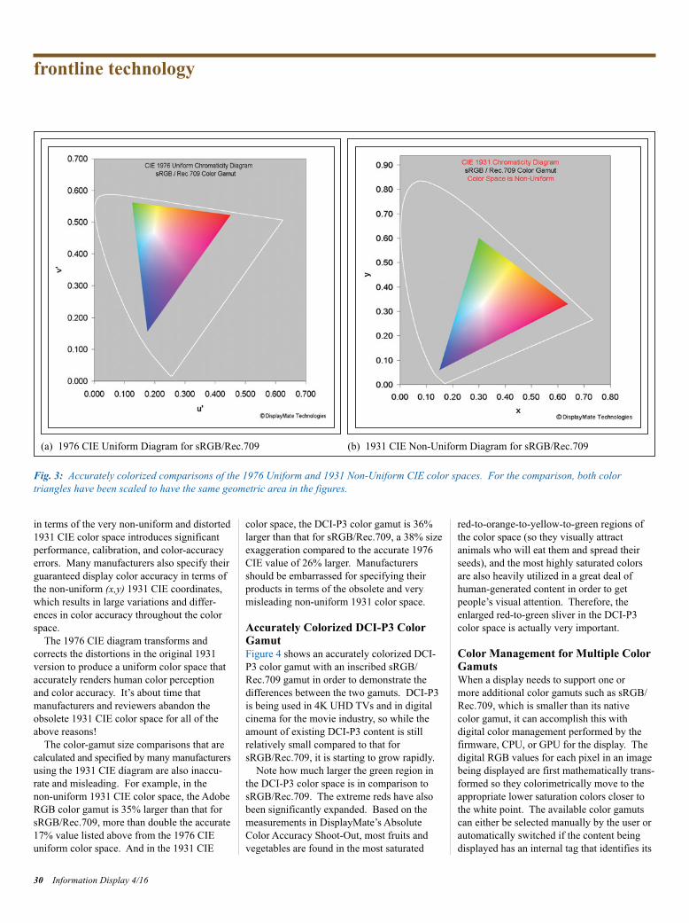
in terms of the very non-uniform and distorted1931 CIE color space introduces significantperformance, calibration, and color-accuracyerrors. Many manufacturers also specify theirguaranteed display color accuracy in terms ofthe non-uniform (x,y) 1931 CIE coordinates,which results in large variations and differ-ences in color accuracy throughout the colorspace.
The 1976 CIE diagram transforms and corrects the distortions in the original 1931version to produce a uniform color space thataccurately renders human color perceptionand color accuracy. It’s about time that manufacturers and reviewers abandon theobsolete 1931 CIE color space for all of theabove reasons!
The color-gamut size comparisons that arecalculated and specified by many manufacturersusing the 1931 CIE diagram are also inaccu-rate and misleading. For example, in the non-uniform 1931 CIE color space, the AdobeRGB color gamut is 35% larger than that forsRGB/Rec.709, more than double the accurate17% value listed above from the 1976 CIEuniform color space. And in the 1931 CIE
color space, the DCI-P3 color gamut is 36%larger than that for sRGB/Rec.709, a 38% sizeexaggeration compared to the accurate 1976CIE value of 26% larger. Manufacturersshould be embarrassed for specifying theirproducts in terms of the obsolete and verymisleading non-uniform 1931 color space.
Accurately Colorized DCI-P3 ColorGamutFigure 4 shows an accurately colorized DCI-P3 color gamut with an inscribed sRGB/Rec.709 gamut in order to demonstrate thedifferences between the two gamuts. DCI-P3is being used in 4K UHD TVs and in digitalcinema for the movie industry, so while theamount of existing DCI-P3 content is still relatively small compared to that forsRGB/Rec.709, it is starting to grow rapidly.
Note how much larger the green region inthe DCI-P3 color space is in comparison tosRGB/Rec.709. The extreme reds have alsobeen significantly expanded. Based on themeasurements in DisplayMate’s AbsoluteColor Accuracy Shoot-Out, most fruits andvegetables are found in the most saturated
red-to-orange-to-yellow-to-green regions ofthe color space (so they visually attract animals who will eat them and spread theirseeds), and the most highly saturated colorsare also heavily utilized in a great deal ofhuman-generated content in order to get people’s visual attention. Therefore, theenlarged red-to-green sliver in the DCI-P3color space is actually very important.
Color Management for Multiple ColorGamutsWhen a display needs to support one or more additional color gamuts such as sRGB/Rec.709, which is smaller than its native color gamut, it can accomplish this with digital color management performed by thefirmware, CPU, or GPU for the display. Thedigital RGB values for each pixel in an imagebeing displayed are first mathematically trans-formed so they colorimetrically move to theappropriate lower saturation colors closer tothe white point. The available color gamutscan either be selected manually by the user orautomatically switched if the content beingdisplayed has an internal tag that identifies its
frontline technology
30 Information Display 4/16
(a) 1976 CIE Uniform Diagram for sRGB/Rec.709 (b) 1931 CIE Non-Uniform Diagram for sRGB/Rec.709
Fig. 3: Accurately colorized comparisons of the 1976 Uniform and 1931 Non-Uniform CIE color spaces. For the comparison, both color triangles have been scaled to have the same geometric area in the figures.
ID Soneira p26-31_Layout 1 7/13/2016 8:39 PM Page 30

native color gamut, and that tag is recognizedby the display’s operating system or firmware.The Apple iPad Pro 9.7 implements color management that automatically switchesbetween the DCI-P3 and sRGB/Rec.709gamuts.
Another, more advanced color-management approach is for the content to include a detailed specification for the colorimetry of the content, and then it is up to the display to implement it as accurately as possible using its native color gamut.
Out With the Old, in With the NewThis overview from the earliest NTSC gamutto the latest DCI-P3 and Rec.2020 gamutsdemonstrates the importance of eliminatingthe widespread use of the obsolete 1953NTSC gamut and the obsolete 1931 CIE diagram in the display industry.
The 1953 NTSC gamut was never actuallyused for production displays and is colorimet-rically different from current standard gamuts,so it is misleading to use it as a reference
gamut. The 1976 CIE diagram transforms andcorrects the large distortions in the original1931 diagram to produce a uniform colorspace that accurately renders human color perception and color accuracy.
Switching to current display technologyand colorimetry standards is tremendouslyoverdue. It is essential not only for properlyspecifying, measuring, manufacturing, andaccurately calibrating displays, but also forcomparing and marketing them to both product manufacturers and consumers.
The display industry and manufacturers ofhigh-tech products should be embarrassed forusing obsolete 63-85 year old standards andcolorimetry! At Display Week 2017, I amreally hoping not to see any obsolete NTSCgamut specifications and obsolete 1931 CIEdiagrams.
References1http://www.displaymate.com/Display_Technology_2014.htm#Ambient_Light
2http://www.displaymate.com/mobile.html3http://www.displaymate.com/iPad_Pro9_ShootOut_1.htm4http://www.displaymate.com/Colors_35.html5http://www.displaymate.com/Color_Accuracy_ShootOut_1.htm n
Information Display 4/16 31
Fig. 4: An accurately colorized DCI-P3 color gamut is shown with an inscribed sRGB/Rec.709gamut.
Display Week 2017SID International Symposium,
Seminar & Exhibition
May 21–26, 2017Los Angeles Convention Center
Los Angeles, California, USA
www.displayweek.org
SAVE THE DATE
JOIN SIDWe invite you to join SID to participate in shapingthe future development of:
• Display technologies and display-related products
• Materials and components for displays and displayapplications
• Manufacturing processes and equipment• New markets and applications
In every specialty you will find SID members as leading contributors to their profession.
http://www.sid.org/Membership.aspx
ID Soneira p26-31_Layout 1 7/10/2016 6:37 PM Page 31
ENGINEERS, developers, analysts,CEOs, investment bankers, and many othersheaded to San Francisco last May for DisplayWeek 2016. With a technical symposium,seminars, short courses, business and marketingconferences, and a three-day exhibition thatincluded the always-popular Innovation Zone,Display Week offered more than one personcould possibly see.
Fortunately, our team of ace reporters –Achin Bhowmik, Jyrki Kimmel, SteveSechrist, and Ken Werner – were on the job,homing in on specific areas of technology andsharing their discoveries via blogs throughoutthe show. (They are also writing longer articlesthat will appear in our September/Octoberpost-show issue.)
We think the blogs are a fun way to get ataste of the really novel things from the show,so we decided to share several of them inprint. If you want to read more, please visitwww.informationdisplay.org.
Augmented and Virtual Reality atDisplay Week: Game On!by Achin BhowmikIn recent years, virtual reality has moved fromscience-fiction movies, to academic researchlabs, to product development in the industry, and, finally, into the hands of consumers in thereal world. A number of marquee devices have been launched into the marketplace, along with some compelling immersive applications. Some cool augmented-reality devices and developerkits have been released as well. The recentpace of progress in both virtual- and aug-mented-reality technologies has been rapid.
In line with this fast-emerging trend in theecosystem, SID decided to create a specialtrack on Augmented and Virtual Reality forDisplay Week 2016. The rich lineup includeda short course, a seminar, a number of invitedand contributed presentations in the sympo-sium, and demonstrations on the exhibit floor.
Displays are the face of some of the most-used electronic devices in our daily lives – thesmartphone, tablet, laptop, monitor, and TV,among other examples. As such, the health ofthe display industry rises and falls with thegrowth and saturation of these devices. Takethe exciting phase of innovation in LCD TVtechnology as an example. The screen sizewent from 24 in. to 32 in. to 40 in. to 55 in. to80 in. and above. The resolution went from720p to full HD to QHD and beyond, whereasthe frame rates went from 60 to 120 fps. Andthere were many more advances – contrast,brightness, color, etc. However, it has gottento the point where further advances in displaytechnology are providing only incrementalbenefits to the consumer. This situation oftenleads to a reduced demand for new featuresand a slowdown in development, and it is tosome degree what those of us in the displayindustry have been facing.
Let’s now turn to virtual reality. It’s a completely different story at the moment. The displays on the best state-of-the-art VRdevices today fall way short of the specifica-tions required for truly immersive and respon-sive experiences, despite the dizzying pace ofdevelopment. The pixel density needs toincrease significantly and latencies must bereduced drastically, along with many other
improvements such as increased field of view,reduced pixel persistence, higher frame rates,etc. Besides the display, the systems alsorequire the integration of accurate sensing andtracking technologies. Augmented-realitydevices impose additional requirements.
So this is exciting for the researchers andengineers in the industry, who must go back tosolving some difficult challenges, with thepotential for big returns. Judging by theexcellent quality of the papers, presentations,and exhibitions at the Display Week, it’s obvious the display ecosystem is all gearedup. AR and VR technology is just what thedisplay industry needs for a massive rejuvena-tion. Game on!
Wearable Displays Sport ClassicDesignsby Jyrki KimmelThere was a time when watches seemed to goout of fashion. Everyone could find out whattime it was by looking at their mobile-phonescreen. But in the last couple of years, “connected watches” have become a wearablepart of the mobile ecosystem and their designhas approached that of classic wristwatches(Fig. 1). The intuitive round-faced hand-dialinterface has pulled through, once again.
How has this development come about?Weren’t we satisfied with the function of thesquare-screen Android devices that appearedin the marketplace about 5 years ago? Apparently not.
The wearables being demonstrated on theexhibition show floor featured many round-faced watch-sized displays. The Withings
Display Week 2016 Show Daily HighlightsColor e-ink, augmented reality’s relationship with human evolution, and displays for smart-watches that really resemble a watch were only a few of the great discoveries that InformationDisplay’s roving reporters made at Display Week 2016 in San Francisco.
by Information Display Staff
32 Information Display 4/160362-0972/4/2016-032$1.00 + .00 © SID 2016
show highlights
ID Staff p32-34_Layout 1 7/10/2016 6:43 PM Page 32
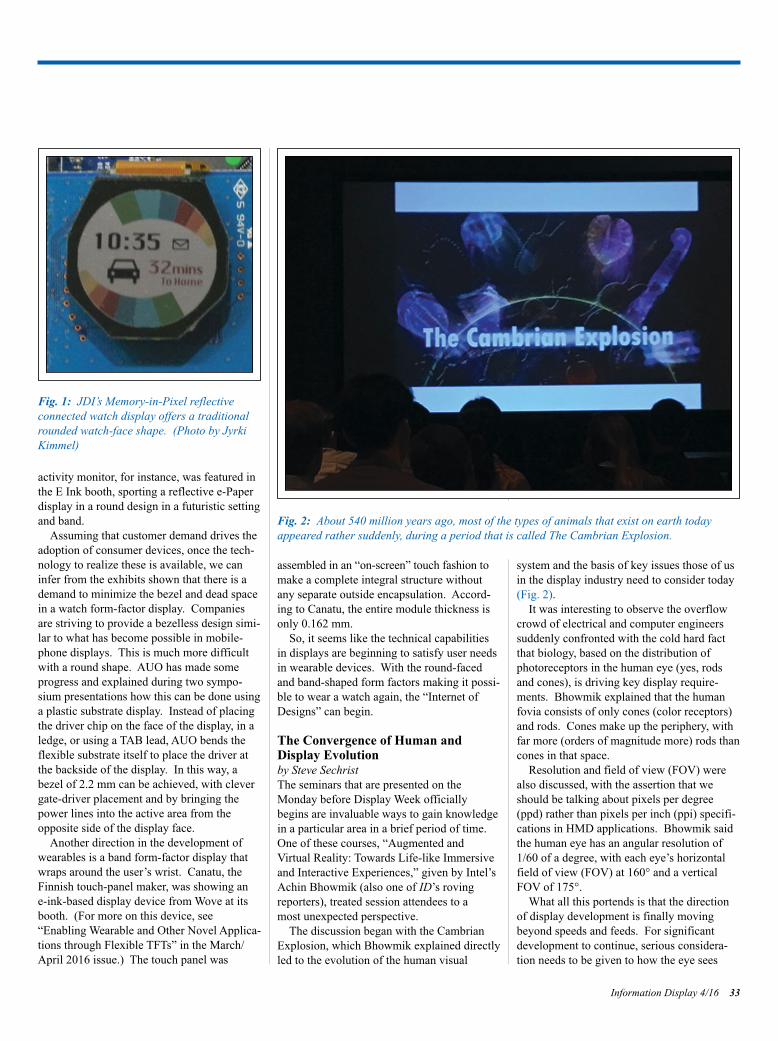
activity monitor, for instance, was featured inthe E Ink booth, sporting a reflective e-Paperdisplay in a round design in a futuristic settingand band.
Assuming that customer demand drives theadoption of consumer devices, once the tech-nology to realize these is available, we caninfer from the exhibits shown that there is ademand to minimize the bezel and dead spacein a watch form-factor display. Companiesare striving to provide a bezelless design simi-lar to what has become possible in mobile-phone displays. This is much more difficultwith a round shape. AUO has made someprogress and explained during two sympo-sium presentations how this can be done usinga plastic substrate display. Instead of placingthe driver chip on the face of the display, in aledge, or using a TAB lead, AUO bends theflexible substrate itself to place the driver atthe backside of the display. In this way, abezel of 2.2 mm can be achieved, with clevergate-driver placement and by bringing thepower lines into the active area from theopposite side of the display face.
Another direction in the development ofwearables is a band form-factor display thatwraps around the user’s wrist. Canatu, theFinnish touch-panel maker, was showing an e-ink-based display device from Wove at itsbooth. (For more on this device, see“Enabling Wearable and Other Novel Applica-tions through Flexible TFTs” in the March/April 2016 issue.) The touch panel was
assembled in an “on-screen” touch fashion tomake a complete integral structure withoutany separate outside encapsulation. Accord-ing to Canatu, the entire module thickness isonly 0.162 mm.
So, it seems like the technical capabilitiesin displays are beginning to satisfy user needsin wearable devices. With the round-facedand band-shaped form factors making it possi-ble to wear a watch again, the “Internet ofDesigns” can begin.
The Convergence of Human andDisplay Evolutionby Steve SechristThe seminars that are presented on the Monday before Display Week officiallybegins are invaluable ways to gain knowledgein a particular area in a brief period of time.One of these courses, “Augmented and Virtual Reality: Towards Life-like Immersiveand Interactive Experiences,” given by Intel’sAchin Bhowmik (also one of ID’s rovingreporters), treated session attendees to a most unexpected perspective.
The discussion began with the CambrianExplosion, which Bhowmik explained directlyled to the evolution of the human visual
system and the basis of key issues those of usin the display industry need to consider today(Fig. 2).
It was interesting to observe the overflowcrowd of electrical and computer engineerssuddenly confronted with the cold hard factthat biology, based on the distribution of photoreceptors in the human eye (yes, rodsand cones), is driving key display require-ments. Bhowmik explained that the humanfovia consists of only cones (color receptors)and rods. Cones make up the periphery, withfar more (orders of magnitude more) rods thancones in that space.
Resolution and field of view (FOV) werealso discussed, with the assertion that weshould be talking about pixels per degree(ppd) rather than pixels per inch (ppi) specifi-cations in HMD applications. Bhowmik saidthe human eye has an angular resolution of1/60 of a degree, with each eye’s horizontalfield of view (FOV) at 160° and a verticalFOV of 175°.
What all this portends is that the directionof display development is finally movingbeyond speeds and feeds. For significantdevelopment to continue, serious considera-tion needs to be given to how the eye sees
Information Display 4/16 33
Fig. 1: JDI’s Memory-in-Pixel reflective connected watch display offers a traditionalrounded watch-face shape. (Photo by JyrkiKimmel)
Fig. 2: About 540 million years ago, most of the types of animals that exist on earth todayappeared rather suddenly, during a period that is called The Cambrian Explosion.
ID Staff p32-34_Layout 1 7/10/2016 6:43 PM Page 33

images and particularly color. Maybe it’s timeto take a refresher course in Biology 101.
E Ink Shows a Color ElectrophoreticDisplay that Popsby Ken WernerThe E Ink Carta reflective electrophoretic display (EPD) is a near-perfect device forreading black text on a white background.But there are applications, such as varioustypes of signage, that demand vibrant color.Until now, the only way to get “full” colorfrom an EPD – at least the only way that E Ink has shown us – is by placing a matrixcolor filter in front of the monochrome display.
The problem with this approach for areflective display is that the 40% of lightreflected from a good EPD is brought down to10–15% by the filter. This results in a limitedgamut of rather dark muddy colors. E Inkshowed the way forward a few years ago with a black, white, and red display, whichmanaged to control particles of three differentcolors using differences in mobility and acleverly designed controlling waveform.
At Display Week 2016, E Ink introduced animpressive expansion of this approach, inwhich particles of four different colors areincluded within each microcapsule, given different mobilities through different sizingand driven with a pulsed controlling wavemovement that permits the creation of thousands of colors, as explained by E Ink’sGiovanni Mancini.
The resulting display showed impressivelybright and saturated colors and drew crowds(Fig. 3). When a new image was written, thedisplay would flash several times. It tookabout 10 sec for a new image to build to itsfinal colors. One possible applicationMancini mentioned is a color e-ink sign pow-ered by photocells.
This is a significant development that willdefinitely expand the range of applicationsEPD can address. n
show highlights
34 Information Display 4/16
Fig. 3: E Ink’s full-color electrophoretic display has four colors of particle and no matrix colorfilter. (Photo: Ken Werner)
For daily display industry news, visit
www.informationdisplay.org
Display Week 2017SID International Symposium, Seminar & Exhibition
May 21–26, 2017Los Angeles Convention Center,
Los Angeles, CA, USA
SAVE THE DATE
For the latest informatin on
Display Week 2017:
www.displayweek.org
J O I N S I DWe invite you to join SID to participate in shaping the future development of:
• Display technologies and display-related products
• Materials and components for displays and display applications
• Manufacturing processes and equipment
• New markets and applications
In every specialty you will find SIDmembers as leading contributors totheir profession.
http://www.sid.org/Membership.aspx
Submit Your News ReleasesPlease send all press releases and newproduct announcements to:Jenny DonelanInformation Display Magazine411 Lafayette Street, Suite 201New York, NY 10003Fax: 212.460.5460e-mail: [email protected]
ID Staff p32-34_Layout 1 7/10/2016 6:43 PM Page 34

Display Week 2017SID International Symposium, Seminar & Exhibition
May 21–26, 2017Los Angeles Convention Center, Los Angeles, California, USA
Display Week 2017 offers synergies unparalleled by any other display event, with attendees and exhibitors whorepresent the top engineering talent from all over the world, as well as leadership from both the commercial andconsumer markets. Display Week is the ideal place to conduct business, discuss systems intengration, networkwith colleagues, and above all, learn about the latest display technologies.
Get started building a better future for your company now!
www.displayweek.org

SID 2017 honors and awardsnominationsOn behalf of the SID Honors and Awards Committee (H&AC), I am appealing for youractive participation in the nomination ofdeserving individuals for the various SID honors and awards. The SID Board of Direc-tors, based on recommendations made by theH&AC, grants all the awards. These awardsinclude five major prizes awarded to individu-als, not necessarily members of SID, basedupon their outstanding achievements. TheKarl Ferdinand Braun prize is awarded for“Outstanding Technical Achievement in, orContribution to, Display Technology.” Theprize is named in honor of the German physi-cist and Nobel Laureate Karl Ferdinand Braunwho, in 1897, invented the cathode-ray tube(CRT). Scientific and technical achievementsthat cover either a wide range of display tech-nologies or the fundamental principles of a specific technology are the prime reasons forawarding this prize to a nominee. The JanRajchman prize is awarded for “OutstandingScientific and Technical Achievement orResearch in the Field of Flat-Panel Displays.”This prize is specifically dedicated to thoseindividuals who have made major contributionsto one of the flat-panel-display technologies or,through their research activities, have advancedthe state of understanding of one of those tech-nologies. The Otto Schade prize is awardedfor “Outstanding Scientific or TechnicalAchievement in the Advancement of Func-tional Performance and/or Image Quality ofInformation Displays.” This prize is namedin honor of the pioneering RCA engineer OttoSchade, who invented the concept of the Modu-lation Transfer Function (MTF) and who usedit to characterize the entire display system,including the human observer. The advance-ment for this prize may be achieved in anydisplay technology or display system or maybe of a more general or theoretical nature.The scope of eligible advancement is broadlyenvisioned to encompass the areas of displaysystems, display electronics, applied visionand display human factors, image processing,and display metrology. The nature of eligibleadvancements may be in the form of theoreti-cal or mathematical models, algorithms, software, hardware, or innovative methods of display-performance measurement and image-quality characterization. Each ofthese above-mentioned prizes carries a $2000
36 Information Display 4/16
NEWSSOCIETY FORINFORMATION
DISPLAY
Nominations are now being solicited from SIDmembers for candidates who qualify for SIDHonors and Awards.
• KARL FERDINAND BRAUN PRIZE.Awarded for an outstanding technicalachievement in, or contribution to, displaytechnology.
• JAN RAJCHMAN PRIZE. Awarded for anoutstanding scientific or technical achieve-ment in, or contribution to, research on flat-panel displays.
• OTTO SCHADE PRIZE. Awarded for anoutstanding scientific or technical achieve-ment in, or contribution to, the advancementof functional performance and/or imagequality of information displays.
• SLOTTOW–OWAKI PRIZE. Awarded foroutstanding contributions to the educationand training of students and professionals inthe field of information display.
• LEWIS & BEATRICE WINNER AWARD.Awarded for exceptional and sustained service to SID.
• FELLOW. The membership grade of Fel-low is one of unusual professional distinc-tion and is conferred annually upon a SIDmember of outstanding qualifications andexperience as a scientist or engineer in thefield of information display who has madewidely recognized and significant contribu-tion to the advancement of the display field.
• SPECIAL RECOGNITION AWARDS.Presented to members of the technical, scientific, and business community (not necessarily SID members) for distinguishedand valued contributions to the information-display field. These awards may be madefor contributions in one or more of the following categories: (a) outstanding technical accomplishments; (b) outstandingcontributions to the literature; (c) outstand-ing service to the Society; (d) outstanding entrepreneurial accomplishments; and (e) outstanding achievements in education.
Nominations for SID Honors and Awards mustinclude the following information, preferablyin the order given below. Nomination Tem-plates and Samples are provided at www.sid.org/awards/nomination.html.
1. Name, Present Occupation, Business andHome Address, Phone and Fax Numbers, andSID Grade (Member or Fellow) of Nominee.
2. Award being recommended:Jan Rajchman PrizeKarl Ferdinand Braun PrizeOtto Schade PrizeSlottow–Owaki Prize Lewis & Beatrice Winner AwardFellow*Special Recognition Award
*Nominations for election to the Grade of Fellow must be supported in writing by at leastfive SID members.
3. Proposed Citation. This should not exceed30 words.
4. Name, Address, Telephone Number, andSID Membership Grade of Nominator.
5. Education and Professional History of Candidate. Include college and/or universitydegrees, positions and responsibilities of eachprofessional employment.
6. Professional Awards and Other Pro fessional Society Affiliations and Grades of Membership.
7. Specific statement by the nominator con-cerning the most significant achievement orachievements or outstanding technical leader-ship that qualifies the candidate for the award.This is the most important consideration forthe Honors and Awards committee, and itshould be specific (citing references when necessary) and concise.
8. Supportive material. Cite evidence of tech-nical achievements and creativity, such aspatents and publications, or other evidence ofsuccess and peer recognition. Cite material thatspecifically supports the citation and statementin (7) above. (Note: the nominee may be askedby the nominator to supply information for hiscandidacy where this may be useful to establishor complete the list of qualifications).
9. Endorsements. Fellow nominations mustbe supported by the endorsements indicated in(2) above. Supportive letters of endorser willstrengthen the nominations for any award.
SID honors and awards nominations
E-mail the complete nomination – including all the above material by October 15, 2016 –to [email protected] with cc to [email protected] or by regular mail to:
Shin-Tson Wu, Honors and Awards Chair, Society for Information Display,1475 S. Bascom Ave., Ste. 114, Campbell, CA 95008, U.S.A.
ID SID News Issue4 p36-38_Layout 1 7/10/2016 7:04 PM Page 36

stipend sponsored by AU Optronics Corp., Sharp Corporation, and Samsung Display, respectively.
The Slottow–Owaki prize is awarded for “Outstanding Contributions to the Educationand Training of Students and Professionals in the Field of Information Display.” This prize is named in honor of Professor H. Gene Slottow, University of Illinois, an inventor of the plasmadisplay and Professor Kenichi Owaki from theHiroshima Institute of Technology and an earlyleader of the pioneering Fujitsu Plasma Displayprogram. The oustanding education and train-ing contributions recognized by this prize is not limited to those of a professor in a formaluniversity, but may also include training givenby researchers, engineers, and managers inindustry who have done an outstanding jobdeveloping information-display professionals.The Slottow–Owaki prize carries a $2000stipend made possible by a generous gift fromFujitsu, Ltd., and Professor Tsutae Shinoda.
The fifth major SID award, the Lewis andBeatrice Winner Award, is awarded for“Exceptional and Sustained Service to theSociety.” This award is granted exclusively to those who have worked hard over manyyears to further the goals of the Society.
The membership grade of SID Fellow is one of unusual professional distinction.Each year the SID Board of Directors elects a limited number (up to 0.1% of the member-ship in that year) of SID members in goodstanding to the grade of Fellow. To be eligi-ble, candidates must have been members atthe time of nomination for at least 5 years, with the last 3 years consecutive. A candidatefor election to Fellow is a member with “Out-standing Qualifications and Experience as aScientist or Engineer in the Field of Informa-tion Display who has made Widely Recog-nized and Significant Contributions to the Advancement of the Display Field” over a sustained period of time. SID members prac-ticing in the field recognize the nominee’swork as providing significant technical con-tributions to knowledge in their area(s) ofexpertise. For this reason, five endorsementsfrom SID members are required to accompanyeach Fellow nomination. Each Fellow nomi-nation is evaluated by the H&AC, based on aweighted set of five criteria. These criteria andtheir assigned weights are creativity andpatents, 30%; technical accomplishments andpublications, 30%; technical leadership, 20%;service to SID, 15%; and other accomplish-ments, 5%. When submitting a Fellow award
nomination, please keep these criteria withtheir weights in mind.
The Special Recognition Award is givenannually to a number of individuals (member-ship in the SID is not required) of the scien-tific and business community for distin-guished and valued contribution in the infor-mation-display field. These awards are givenfor contributions in one or more of the follow-ing categories: (a) Outstanding TechnicalAccomplishments, (b) Outstanding Contribu-tions to the Literature, (c) Outstanding Service to the Society, (d) Outstanding Entrepreneurial Accomplishments, and (e) Outstanding Achievements in Education.When evaluating the Special RecognitionAward nominations, the H&AC uses a five-level rating scale in each of the above-listedfive categories, and these categories haveequal weight. Nominators should indicate the category in which a Special RecognitionAward nomination is to be considered by theH&AC. More than one category may be indicated. The nomination should, of course,stress accomplishments in the category or categories selected by the nominator.
While an individual nominated for anaward or election to Fellow may not submithis/her own nomination, nominators may, ifnecessary, ask a nominee for information thatwill be useful in preparing the nomination. The nomination process is relatively simple, butrequires that the nominator and perhaps somecolleagues devote a little time to preparationof the supporting material that the H&ACneeds in order to evaluate each nomination forits merit. It is not necessary to submit a com-plete publication record with a nomination.Just list the titles of the most significant half a dozen or less papers and patents authored by the nominee, and list the total number ofpapers and patents he/she has authored.
Determination of the winners for SID hon-ors and awards is a highly selective process.On average, less than 30% of the nominationsare selected to receive awards. Some of themajor prizes are not awarded every year dueto the lack of sufficiently qualified nominees.On the other hand, once a nomination is sub-mitted, it will stay active for three consecutiveyears and will be considered three times bythe H&AC. The nominator of such a nomina-tion may improve the chances of the nomina-tion by submitting additional material for thesecond or third year that it is considered, butsuch changes are not required.
Descriptions of each award and the lists ofprevious award winners can be found atwww.sid.org/Awards/IndividualHonorsandAwards.aspx. Nomination forms can bedownloaded by clicking on “click here” at the bottom of the text box on the above sitewhere you will find Nomination Templates inboth MS Word (preferred) and Text formats.Please use the links to find the Sample Nomi-nations, which are useful for composing your nomination since these are the actualsuccessful nominations for some previous SID awards. Nominations should preferablybe submitted by e-mail. However, you canalso submit nominations by ordinary mail ifnecessary.
Please note that with each Fellow nomina-tion, only five written endorsements by five SIDmembers are required. These brief endorse-ments – a minimum of 2–3 sentences to a maxi-mum of one-half page in length – must statewhy clearly and succinctly, in the opinion of theendorser, the nominee deserves to be elected toa Fellow of the Society. Identical endorse-ments by two or more endorsers will be auto-matically rejected (no form letters, please).Please send these endorsements to me either by e-mail (preferred) or by hardcopy to theaddress stated in the accompanying text box.Only the Fellow nominations are required tohave these endorsements. However, I encour-age you to submit at least a few endorsementsfor all nominations since they will frequentlyadd further support to your nomination.
All 2017 award nominations are to be submitted by October 15, 2016. E-mail your nominations directly to [email protected] with cc to [email protected]. If that is not possible,then please send your hardcopy nomination by regular mail.
As I state each year: “In our professionallives, there are few greater rewards thanrecognition by our peers. For an individual inthe field of displays, an award or prize fromthe SID, which represents his or her peersworldwide, is a most significant, happy, andsatisfying experience. In addition, the overallreputation of the society depends on the indi-viduals who are in its ‘Hall of Fame.’
When you nominate someone for an award or prize, you are bringing happiness to an indi-vidual and his or her family and friends, and you are also benefiting the society as a whole.”
Thank you for your nomination in advance.— Shin-Tson Wu
Chair, SID Honors & Awards Committee
Information Display 4/16 37
ID SID News Issue4 p36-38_Layout 1 7/10/2016 7:04 PM Page 37

Society for Information DisplayAnnounces New ExecutiveLeadership TeamThe Society for Information Display (SID)recently announced the members of its newleadership team, all of whom are distinguishedexperts in the display industry. ProfessorYong-Seog Kim has become the new SIDpresident, while Dr. Helge Seetzen moves into the role of president-elect. Takatoshi Tsujimura will serve as the new treasurer and Dr. Achin Bhowmik is the executive com-mittee’s new secretary. Three new regionalvice-presidents were also selected: SriramPeruvemba (Americas), P. Kathirgamanathan(Europe), and Xiaolin Yan (Asia).
Kim has been an active member of SID forthe past 15 years and is a distinguished professor in the Department of Materials Science and Engineering at Hongik Universityin Seoul, Korea. He is regarded as one of theleading researchers throughout the world inmaterials development and processing forinformation displays.
President-elect Seetzen is a multi-mediatechnology entrepreneur with particularexpertise in the university tech transfer space.He is currently the General Partner ofTandemLaunch Ventures – a consumer-electronics investment fund – and has heldexecutive roles at Dolby Laboratories and atBrightSide Technologies, which he co-founded.
With more than 20 years of LCD andOLED industry experience, newly appointedtreasurer Tsujimura also serves as the generalmanager and department head of Konica-Minolta’s OLED business.
Bhowmik, the new SID secretary, has beenwith Intel Corporation for more than 16 years.He currently serves as vice-president and general manager of the perceptual computinggroup at Intel.
Dr. Amal Ghosh, outgoing SID president,stated, “It’s been a great honor to serve aspresident for the world’s premier display-technology organization over the past 2 years.SID both attracts the very best display tech-nologists and fosters leading-edge R&D. My predecessors on the board, through theirdedicated service, have led SID to this rank, and I have no doubt that Professor Kim will succeed in taking it to new levels ofexcellence.”
Noted Kim, “I would like to thank Amal forall he has done over the past 2 years toadvance the organization’s goals and visibilityas more new cutting-edge displays enter ourlives. I am truly honored to assume thisresponsibility, and I look forward to helpingusher in the next generation of dynamic technologies and products that are beingdeveloped. It will be an exciting challenge tohelp ensure that SID keeps pace, while contin-uing to advance its reputation as the displayindustry’s leading organization. I’ve enjoyedworking with the current executive team, andas we all move into our new roles, I look forward to a dynamic and progressive next 2 years.”
(ID magazine acknowledges MCA PublicRelations, on whose announcement this articleis based.) n
38 Information Display 4/16
sid news
J O I N S I DWe invite you to join SID to participate in shaping the future development of:
• Display technologies and display-related products
• Materials and components for displays and display applications
• Manufacturing processes and equipment
• New markets and applications
In every specialty you will find SIDmembers as leading contributors totheir profession.
http://www.sid.org/Membership.aspx
EXH IB I T NOW AT
EXHIBITION DATES:May 23–25, 2017Los Angeles Convention CenterLos Angeles, CA, USAEXHIBITION HOURS:Tuesday, May 23 10:30 am – 6:00 pmWednesday, May 249:00 am – 5:00 pmThursday, May 25 9:00 am – 2:00 pm
CONTACTS FOR EXHIBITS ANDSPONSORSHIPS:Jim BuckleyExhibition and Sponsorship Sales, Americas and [email protected] +1 (203) 502-8283Sue ChungExhibition and Sponsorship Sales, Asia [email protected] +1 (408) 489-9596
Display Week 2017SID International Symposium, Seminar & Exhibition
May 21–26, 2017Los Angeles Convention Center,
Los Angeles, CA, USA
ID SID News Issue4 p36-38_Layout 1 7/10/2016 7:04 PM Page 38

Call for Papers on
Vehicle Displays The Journal of the SID is soliciting original contributed papers on Vehicle Display, to be
published in a Special Section in the Journal of the SID in the first quarter of 2017. Topics of interest include, but are not limited to: -Automotive displays -Head-up displays -Cockpit displays -Rugged displays -New concepts for vehicle displays
Papers can deal with technological aspects of manufacturing, image quality and reliability
issues, form factors, deformability, power consumption, human factors related to the use of vehicle displays, etc.
Authors are invited to submit manuscripts online in electronic files to the JSID at:
http://mc.manuscriptcentral.com/sid Authors submitting their manuscript must identify their manuscripts as being submitted
for the paper type in Step 1 of the
Step 5 of the submission process. The Information for Authors document provides a complete set of guidelines and requirements required for the preparation and submission of a manuscript, including a discussion of the formatting requirements and the journal page charge policy.
The deadline for the submission of manuscripts is September 15th, 2016 The Guest Editors for this Special Section will be:
Rashmi Rao, [email protected] Haruhiko Okumura, [email protected]
Please direct any questions about this special issue to the Editor-in-Chief of JSID at
[email protected] or to one of the Guest Editors
ID JSID Call for Papers_Layout 1 7/10/2016 7:07 PM Page 39
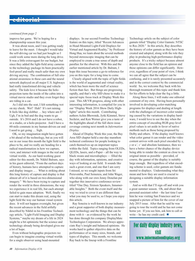
improve her game. We’re hoping for a championship season this year.It was about noon, and I was getting ready
to leave for the meet. I thought I would takethe self-driving car we had just bought so Icould work some more during the long drive.It was a little extravagant for our budget, butsince they added the light-field array camerasto the technology package its been practicallyfool-proof and really much safer than my owndriving anyway. The combination of full situ-ational awareness in these cars and the neuralnetwork deployed on all major U.S. highwayshad really transformed driving and vehiclesafety. The kids love it because the holo-projection turns the inside of the cabin into avirtual movie studio and they even forget theyare riding in a car. As I slid into the seat, I felt something wet
on my cheek. Wet? Huh? It’s not raining. It feels like dog slobber … hey where am I?Ugh, I’m in bed and the dog wants to go outside. It’s 2016 and I do not have a robot,or a studio, or a holo-projector. And I have a60-mile commute in my human-driven car andI need to get going … Sigh.OK, so my imagination might have gotten
a bit ahead of the technology, but as you willsee in our issue this month the light field is theplace to be, and we really are heading for aradical transformation in how we capture,view, and interact with images in the real andvirtual worlds. As our hard-working guesteditor for this month, Dr. Nikhil Balram, saysin his guest editorial, “From the earliest daysof history, humans have attempted to captureand display images ... . What is striking aboutthis long history of capture and display is thatalmost all of it is based on two-dimensionalimagery.” We have been trying to capture andrender the world in three dimensions, the waywe experience it in real life, but each attemptfailed to gain mass adoption. Well, finally wecan start to make this dream real, using thelight field the way our human visual systemdoes. It will not happen overnight, but giventhe recent advances in the field artfullydescribed by Nikhil in his Frontline Technol-ogy article, “Light-Field Imaging and DisplaySystems,” maybe my dream of a life in 2024might be a bit optimistic but the science andtechnology already being developed gives mea lot of hope. Even without holographic projectors we
can begin to imagine creating virtual worldsfor a single observer using head-mounted
displays. In our second Frontline Technologyfeature on this topic, titled “Recent Advancesin Head-Mounted Light-Field Displays forVirtual and Augmented Reality,” by ProfessorHong Hua, we learn about the several methodsbeyond stereoscopic imaging that can beemployed to create a true sense of depth andparallax for the observer. With this and theearlier mentioned article by Dr. Balram, Ihope this issue becomes a go-to reference foryou on this topic for a long time to come.Closely aligned with the topic of light fields
is the world of augmented and virtual reality,which has been more the stuff of science fiction than fact. But things are progressingrapidly, and that’s why SID chose to make it aspecial topic focus track at Display Week thisyear. This AR/VR progress, along with otherinteresting information, is compiled for you inour “Display Week 2016 Show Daily High-lights” article this month. Contributingauthors Achin Bhowmik, Jyrki Kimmel, SteveSechrist, and Ken Werner give you a taste ofthe highlights ahead of the full show-issuecoverage coming next month in InformationDisplay.Ahead of Display Week this year, the Bay
Area SID chapter held a one-day marathontechnical conference for people looking tocatch themselves up on important topicswithin the field. Topics ranging from OLEDs,QLEDs, lasers, and e-Paper – all the way toblack swans and microdisplays — filled theday with information, opinions, and creativeways of looking at our field. It sounds likesuch a great event, and one that I am sorry I missed, so we sought inputs from Sri Peruvemba, Paul Semenza, and John Wager,who along with our own Jenny Donelan puttogether this innovative conference reviewtitled “One Day, Sixteen Speakers, Innumer-able Insights.” Both the event itself and theway we tried to cover it are different thanwhat you may be used to, so I hope you enjoythis article.Ray Soneira is well-known in our industry
and a great supporter of both display measure-ment technology and the things that can bedone with it – as evidenced by the work hehas done through his company DisplayMateTechnologies Corporation. We always appre-ciate Ray’s insight and balanced opinions. Heworks hard to gather objective data on the performance of so many sizes, brands, andtypes of displays. This month, we welcomeRay back to the lineup with a Frontline
Technology article on the subject of colorgamuts titled “Display Color Gamuts: NTSCto Rec.2020.” In this article, Ray describesthe history of color gamuts as they have beencreated and adopted, along with the role theyplay in producing high-performance displayproducts. It’s a tricky subject because almostanyone close to the field has an opinion andthose opinions can differ significantly. How-ever, regardless of your point of view, I thinkwe can all agree that the subject can be confusing, and it is rarely presented accuratelyand in the correct context by the commercialworld. So, we welcome Ray back with histhorough treatment of this topic and thank himfor his efforts to help clear the fog a little. Along these lines, I will make one editorial
comment of my own. Having been personallyinvolved in developing color-matching programs for displays and dealing at lengthwith the challenges of incorrect color render-ing caused by the variations in display hard-ware, I would love to see the day when theentire concept of encoding RGB gray-levelpixel values is set aside in favor of nativemethods such as those being proposed byDolby and others. If the display itself knowswhat color gamut it can render and the videocontent arrives with each pixel encoded by x,y or u’, v’ and absolute luminance, then wehave a better chance of the display devicebeing able to render the content as close to itsoriginal intent as possible – provided, ofcourse, the gamut of the display is suitablylarge enough. But regardless of what encod-ing scheme is used, color gamuts are funda-mental to displays. Understanding what theymean and how they are used is crucial todesigning a suitable display information system.And so with that I’ll sign off and wish you
a great summer season. Oh, and about thatpersonal-assistant robot – the last time I sawhim he was visiting San Francisco and wesnapped a picture of him for the cover of ourJuly 2015 issue. After that he said he wasgoing to tour the world and he has not comehome yet. If you see him, ask him to call orwrite – he has my credit card. n
continued from page 2
40 Information Display 4/16
editorial
For daily display industry news,visit
www.informationdisplay.org
ID Editorial Issue4 p2_Layout 1 7/11/2016 8:46 PM Page 40
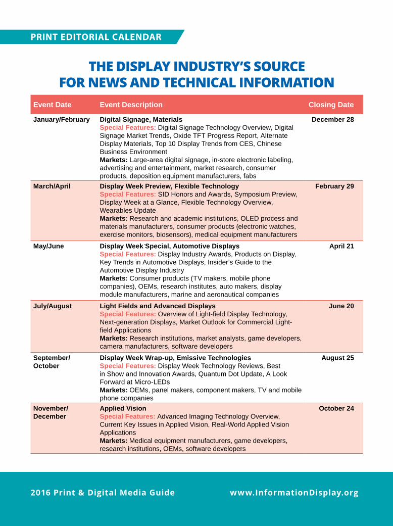
www.InformationDisplay.org2016 Print & Digital Media Guide
PRINT EDITORIAL CALENDAR
THE DISPLAY INDUSTRY’S SOURCE FOR NEWS AND TECHNICAL INFORMATION
Event Date Event Description Closing Date
January/February Digital Signage, MaterialsSpecial Features: Digital Signage Technology Overview, Digital Signage Market Trends, Oxide TFT Progress Report, Alternate Display Materials, Top 10 Display Trends from CES, Chinese Business EnvironmentMarkets: Large-area digital signage, in-store electronic labeling, advertising and entertainment, market research, consumer products, deposition equipment manufacturers, fabs
December 28
March/April Display Week Preview, Flexible TechnologySpecial Features: SID Honors and Awards, Symposium Preview, Display Week at a Glance, Flexible Technology Overview, Wearables UpdateMarkets: Research and academic institutions, OLED process and materials manufacturers, consumer products (electronic watches, exercise monitors, biosensors), medical equipment manufacturers
February 29
May/June Display Week Special, Automotive DisplaysSpecial Features: Display Industry Awards, Products on Display, Key Trends in Automotive Displays, Insider’s Guide to the Automotive Display IndustryMarkets: Consumer products (TV makers, mobile phone companies), OEMs, research institutes, auto makers, display module manufacturers, marine and aeronautical companies
April 21
July/August Light Fields and Advanced DisplaysSpecial Features: Overview of Light-field Display Technology, Next-generation Displays, Market Outlook for Commercial Light-field ApplicationsMarkets: Research institutions, market analysts, game developers, camera manufacturers, software developers
June 20
September/ October
Display Week Wrap-up, Emissive TechnologiesSpecial Features: Display Week Technology Reviews, Best in Show and Innovation Awards, Quantum Dot Update, A Look Forward at Micro-LEDsMarkets: OEMs, panel makers, component makers, TV and mobile phone companies
August 25
November/ December
Applied VisionSpecial Features: Advanced Imaging Technology Overview, Current Key Issues in Applied Vision, Real-World Applied Vision ApplicationsMarkets: Medical equipment manufacturers, game developers, research institutions, OEMs, software developers
October 24
SID-2016.indd 4 11/18/15 7:55 PM
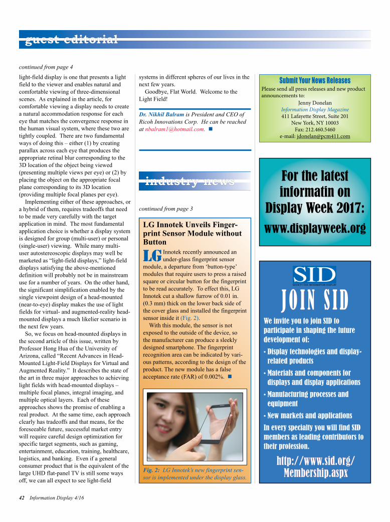
light-field display is one that presents a lightfield to the viewer and enables natural andcomfortable viewing of three-dimensionalscenes. As explained in the article, for comfortable viewing a display needs to createa natural accommodation response for eacheye that matches the convergence response inthe human visual system, where these two aretightly coupled. There are two fundamentalways of doing this – either (1) by creating parallax across each eye that produces theappropriate retinal blur corresponding to the3D location of the object being viewed (presenting multiple views per eye) or (2) byplacing the object on the appropriate focalplane corresponding to its 3D location (providing multiple focal planes per eye).
Implementing either of these approaches, ora hybrid of them, requires tradeoffs that needto be made very carefully with the targetapplication in mind. The most fundamentalapplication choice is whether a display systemis designed for group (multi-user) or personal(single-user) viewing. While many multi-user autostereoscopic displays may well bemarketed as “light-field displays,” light-fielddisplays satisfying the above-mentioned definition will probably not be in mainstreamuse for a number of years. On the other hand,the significant simplification enabled by thesingle viewpoint design of a head-mounted(near-to-eye) display makes the use of lightfields for virtual- and augmented-reality head-mounted displays a much likelier scenario inthe next few years.
So, we focus on head-mounted displays inthe second article of this issue, written by Professor Hong Hua of the University of Arizona, called “Recent Advances in Head-Mounted Light-Field Displays for Virtual andAugmented Reality.” It describes the state ofthe art in three major approaches to achievinglight fields with head-mounted displays –multiple focal planes, integral imaging, andmultiple optical layers. Each of theseapproaches shows the promise of enabling areal product. At the same time, each approachclearly has tradeoffs and that means, for theforeseeable future, successful market entrywill require careful design optimization forspecific target segments, such as gaming,entertainment, education, training, healthcare,logistics, and banking. Even if a general consumer product that is the equivalent of thelarge UHD flat-panel TV is still some waysoff, we can all expect to see light-field
systems in different spheres of our lives in thenext few years.
Goodbye, Flat World. Welcome to theLight Field!
Dr. Nikhil Balram is President and CEO ofRicoh Innovations Corp. He can be reachedat [email protected]. n
continued from page 4
42 Information Display 4/16
guest editorial
continued from page 3
industry news
LG Innotek Unveils Finger-print Sensor Module withoutButton
LG Innotek recently announced anunder-glass fingerprint sensor
module, a departure from ‘button-type’modules that require users to press a raisedsquare or circular button for the fingerprintto be read accurately. To effect this, LGInnotek cut a shallow furrow of 0.01 in.(0.3 mm) thick on the lower back side ofthe cover glass and installed the fingerprintsensor inside it (Fig. 2).
With this module, the sensor is notexposed to the outside of the device, so the manufacturer can produce a sleeklydesigned smartphone. The fingerprintrecognition area can be indicated by vari-ous patterns, according to the design of theproduct. The new module has a falseacceptance rate (FAR) of 0.002%. n
Fig. 2: LG Innotek’s new fingerprint sen-sor is implemented under the display glass.
J O I N S I DWe invite you to join SID to participate in shaping the future development of:
• Display technologies and display-related products
• Materials and components for displays and display applications
• Manufacturing processes and equipment
• New markets and applications
In every specialty you will find SIDmembers as leading contributors totheir profession.
http://www.sid.org/Membership.aspx
For the latest informatin on
Display Week 2017:
www.displayweek.org
Submit Your News ReleasesPlease send all press releases and new productannouncements to:
Jenny DonelanInformation Display Magazine411 Lafayette Street, Suite 201
New York, NY 10003Fax: 212.460.5460
e-mail: [email protected]
ID Guest Editorial Issue4 p4,42_Layout 1 7/10/2016 5:00 PM Page 42

Information Display 4/16 43
Ask us about• E Newsletter Sponsorship• Banner Advertising on
www. Informationdisplay.org• Custom E blast
ALL WITH LEAD GENERATION METRICS
• Display Week Wrap up issue – use this as an addition to your Company’s overall print marketing program
• SID- Information Display AD Bundle – Print – Digital – E Blast Marketing
Contact: Roland Espinosa, Senior Account ManagerPrint & E-Media Advertising
201-748-6819 • [email protected]
Display Week 2017SID International Symposium, Seminar & Exhibition
May 21–26, 2017Los Angeles Convention Center Los Angeles, California, USA
www.displayweek.org
SAVE THE DATE
ID p43 ONLY_Layout 1 7/10/2016 7:13 PM Page 43
Abrisa TechnologiesAcerAdvantechApple, Inc.Applied Concepts, Inc.Applied Materials, Inc.AU Optronics Corp.CASIOCoretronicCynora GmbHdpiXDawar TechnologiesDontechE Ink HoldingsEarth LCDEpoxy TechnologyeMagin Corp.Europtec USA, Inc.FocalTech SystemsFUJIFILM Dimatix, Inc.Gigaphoton, Inc.GISHenkelIEEIndustrial Technology Research Institute
InnoluxI-PEXIRTSJapan Display, Inc.Japan Patent OfficeKuraray Co., Ltd.LEIA, Inc.LXD Research & Display,LLC
MegaChips Corp.Merck Display Technologies, Ltd.
MeritecMitsubishi Chemical Corp.
MY Polymers, Ltd.Nano-Proprietary, Inc.NANOSYSNLT TechnologiesNoritake Itron Corp.Novaled AGNvidiaOculus Panasonic Corp.Pixel ScientificPower OLEDs
RealDRicohRolic TechnologiesSakai Display ProductsSartomer AmericasSharp Corp.TDMDATDUATeijin Dupont FilmsJapan, Ltd.
TFD, Inc. TLC International TOUCH TURNSTPK Touch Solutions,Inc.
TTLAUniversal Display Corporation
US Micro ProductsVestel ElectronicsVisionoxWestar Display Technologies, Inc.
Wintek Corp.
Electronic Assembly ....................5Ellsworth Adhesives.....................5Instrument Systems ..................C3Masterbond.................................5
Radiant Vision Systems ............C2TFD.........................................C4Vehicle Displays Detroit............25
44 Information Display 4/16
corporate members index to advertisers
Sales Office
Steven JezzardGlobal Advertising DirectorWiley111 River StreetHoboken, NJ [email protected]
Global Sales Office (Except Japan/China)
Roland EspinosaSr. Account ManagerPrint & E Media AdvertisingWiley111 River StreetHoboken, NJ [email protected]
Japan Sales Office
Kimiyoshi IshibashiAssociate Commercial Director – JapanJohn Wiley & Sons (Asia) Pte Ltd.Frontier Koishikawa Bldg., 4F1-28-1 Koishikawa, Bunkyo-kuTokyo 112-0002, [email protected]
China Sales Office
Ying WangCorporate Sales Manager – ChinaJohn Wiley & Sons (Asia) Pte Ltd.1402-1404 Cross Tower318 Fuzhou Road, Huangpu DistrictShanghai 200001, People’s Republic ofChina
+86 21 5116 [email protected]
SILVER CORPORATE MEMBERS
GOLD CORPORATE MEMBERS
Corporate Members
ID Ad Index Issue4 p44_Layout 1 7/10/2016 7:21 PM Page 44

The new LumiCol 1900 from Instrument Systems.
y One-shot characterization of flat panel displays
y Optimized for production testing
y Built-in reference spot-colorimeter
y Powerful LumiSuite software
y High cost-efficiency
www.LumiCol-1900.com We bring quality to light.
Instrument Systems Germany · Phone: +49 89 45 49 43 58 · [email protected] · www.instrumentsystems.com
Speed up your cycle time
NEW

Economical and Superior Coatings and Products
Thin Film Devices Incorporated
1180 N. Tustin Avenue, Anahiem, CA 92807
Phone: 714.630.7127
Fax: 714.630.7119
Email: [email protected]
China Supply Chain: Group International [email protected]
Korean Manufacturing: Ion-Tek [email protected]
Taiwan Manufacturing: Acrosense Technologies
Imbedded Mesh(≤ 5 OPS, T% ≥ 90% @ 420-680nm)
Glass Interposer
Flexible Dye Cell
OLED + Bank
Foundry Capability for MEMs, OLED, Banks, OPV, Dye Cell, Interposer, Chip on Glass & Others
PHOTOETCH & PATTERNING CAPABILITIES: SMALL TO LARGE SCALE
STANDARD COATING & SERVICES:
• STD TCO’s ITO/IZO/AZO/FTO & WRTCO™
• BBAR 200µm – 12µm Multiple Range
• IMITO™ (EMI & Heaters) Several Types
• Hot & Cold Mirrors Several Types
• Black Mask: Black Cr, Nb or Resist
• Custom P-Caps Several Types
• Color Filters (Resist Type) Several Types
• Lamination: Ruggedization, Glass to Glass, Anti-Vandal, Filters, EMI/Heater to LCD
MEMs
Micro Blinder