influence of variable valve timings on the gas … university institutional repository influence of...
TRANSCRIPT
Loughborough UniversityInstitutional Repository
Influence of variable valvetimings on the gas exchange
process in a controlledauto-ignition engine
This item was submitted to Loughborough University's Institutional Repositoryby the/an author.
Citation: MILOVANOVIC, N., CHEN, R. and TURNER, J., 2004. Influenceof variable valve timings on the gas exchange process in a controlled auto-ignition engine. Proceedings of the Institution of Mechanical Engineers, PartD: Journal of Automobile Engineering, 218(5), pp. 567-583.
Additional Information:
• This article has been published in the journal, Proceedings of theInstitution of Mechanical Engineers, Part D: Journal of Automo-bile Engineering [ c© PEP]. The definitive version is available at:http://dx.doi.org/10.1243/095440704774061228
Metadata Record: https://dspace.lboro.ac.uk/2134/4501
Version: Published
Publisher: c© IMechE / Professional Engineering Publishing
Please cite the published version.

This item was submitted to Loughborough’s Institutional Repository (https://dspace.lboro.ac.uk/) by the author and is made available under the
following Creative Commons Licence conditions.
For the full text of this licence, please go to: http://creativecommons.org/licenses/by-nc-nd/2.5/
567
In�uence of variable valve timings on the gas exchangeprocess in a controlled auto-ignition engine
N Milovanovic1*, R Chen1 and J Turner21Aeronautical and Automotive Department, Loughborough University, Loughborough, UK
2Powertrain Research Department, Lotus Engineering, UK
Abstract: The controlled auto-ignition (CAI ) engine concept has the potential to be highly e�cient
and to produce low NOx
and particulate matter emissions. However, the problem of controlling the
combustion over the entire load/speed range limits its practical application. The CAI combustion is
controlled by the chemical kinetics of the charge mixture, with no in�uence of the �ame di�usion or
turbulent propagation. Therefore, to achieve successful control of the CAI process, the composition,
temperature and pressure of the charge mixture at the inlet valve closure (IC ) point have to be
controlled. The use of the variable valve timing strategy, which enables quick changes in the amount
of trapped hot exchaust gases, shows the potential for control of CAI combustion. The aim of this
paper is to analyse the in�uence of the variable valve timing strategy on the gas exchange process,
the process between the �rst valve open event (EO) and the last valve closing event (IC ), in a CAI
engine fuelled with standard gasoline fuel (95RON). The gas exchange process a�ects the engine
parameters and charge properties and therefore plays a crucial role in determining the control of the
CAI process. Analysis is performed by experimental and modelling approaches. A single-cylinder
research engine equipped with a fully variable valvetrain (FVVT) system was used for the experi-
mental study. A combined code consisting of a detailed chemical kinetics code and one-dimensional
�uid dynamics code was used for the modelling study. The results obtained indicate that the variable
valve timing strategy has a strong in�uence on the gas exchange process, which in turn in�uences
the engine parameters and the cylinder charge properties, and hence the control of the CAI process.
The EC timing has the strongest e�ect, followed by the IO timing, while the EO and IC timings have
minor e�ects.
Keywords: controlled auto-ignition, control, variable valve timing, gas exchange process, internal
exhaust gas recirculation, gasoline
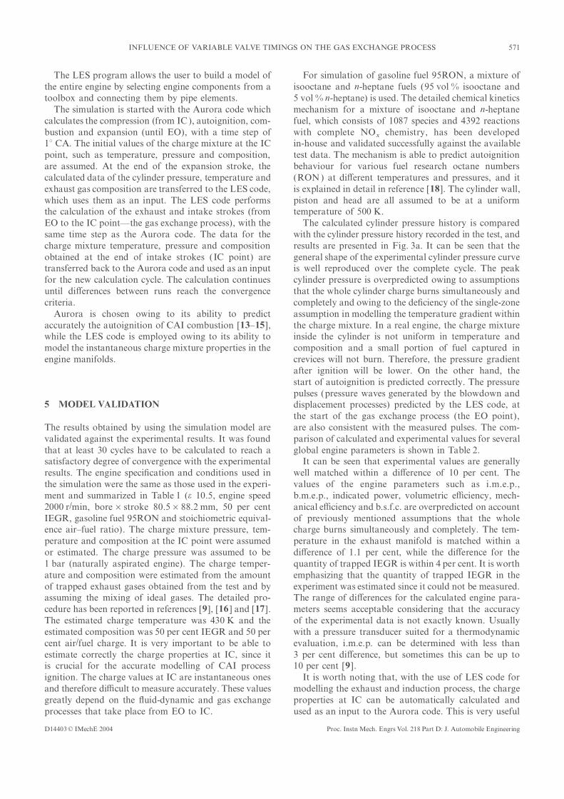
NOTATION EC exhaust valve closure
EO exhaust valve open
FVVT fully variable valvetrainABDC after bottom dead centre
GEP gas exchange processATDC after top dead centrei.m.e.p. (PMI ) indicated mean e�ective pressureATDCoverlap after top dead centre overlapIC inlet valve closure(gas exchange process)IEGR internal exhaust gas recirculationAVT active valve trainIO inlet valve openb.m.e.p. break mean e�ective pressureMOP maximum open point (valve)b.s.f.c. break speci�c fuel consumptionn revolutions per minuteBDC bottom dead centreRON research octane numberBTDCoverlap before top dead centre overlapTDC top dead centre(gas exchange process)TDCcomb top dead centre combustionCA crank angle
e compression ratioThe MS was received on 13 August 2003 and was accepted after revision QEC exhaust valve closure timing (° C)for publication on 30 January 2004. Q
EO exhaust valve open timing (° C)* Corresponding author: Aeronautical and Automotive Engineering
QIC inlet valve closure timing (° C)Department, Loughborough University, Loughborough, Leicester,
LE11 3TU, UK. QIO inlet valve open timing (° C)
D14403 © IMechE 2004 Proc. Instn Mech. Engrs Vol. 218 Part D: J. Automobile Engineering

568 N MILOVANOVIC, R CHEN AND J TURNER
1 INTRODUCTION (i.e. charge mixture properties) at the beginning of the
compression stroke [the inlet valve closure (IC ) point ].
As CAI combustion is kinetically controlled, the rate ofControlled autoignition (CAI ) combustion is a process
that combines features of the spark ignition (SI ) and heat release depends on correct combustion phasing and
is closely linked with the ignition delay. Therefore, acompression ignition (CI ) processes. In a CAI engine
the air and fuel are premixed homogeneously prior to successful control strategy has to be able to control the
charge mixture properties at the IC point over the entireignition and then ignited by the compression from
the piston motion. The ignition is provided at multiple load/speed range.
Di�erent methods that have the potential to con-points and therefore the charge gives a parallel energy
release. This results in uniform and simultaneous auto- trol the start of autoignition and the heat release rate of
CAI combustion, together with their e�ectiveness andignition and chemical reaction throughout the whole
charge without �ame propagation. In CAI combustion practical feasibility, have been discussed in reference [5 ].
Internal exhaust gas recirculation (IEGR), i.e. trappingthe chemical kinetics of the air–fuel mixture plays a
crucial role, with no requirements for turbulence and the hot exhaust gases into the cylinder, accomplished
by a fully variable valvetrain (FVVT) system, appearsmixing.
Controlled autoignition combustion was initially recog- to be the most promising and the most feasible way of
achieving CAI combustion control in a certain loadnized in two-stroke engines in the late 1970s by Onishiet al. [1 ] and Noguchi et al. [2 ]. They observed that range [6 ]. The FVVT system allows quick changes in
the cylinder charge temperature and composition bythe premixed air–fuel mixture ignited simultaneously
at many points without obvious �ame propagation. retaining the hot exhaust gases from previous cycles.
By varying the amount of hot exhaust gases, the tem-The notion that CAI combustion is dominated by the
chemical kinetics of the air–fuel mixture employed has perature and composition of the charge mixture can be
adjusted.been supported by recent spectroscopic and imaging
investigations [3, 4 ]. The results obtained indicate that The aim of this paper is to analyse the in�uence of
the variable valve timing strategy on the gas exchangethe ignition occurs simultaneously at multiple points
with no �ame propagation. process (GEP) in a CAI engine fuelled with standard
gasoline fuel (95RON). The GEP takes place betweenThe CAI engine o�ers bene�ts in comparison with the
spark ignition and compression ignition engines: higher the �rst valve open event (EO) and the last valve closing
event (IC ). Since the GEP precedes the compressione�ciency due to elimination of throttling losses at part
and idle loads; the possibility of using high compression stroke, where the autoignition and heat release processes
occur, it in�uences the engine parameters and chargeratios since it is not knock limited; signi�cantly lower
NOx
and particulate matter emissions owing to a much mixture properties, and hence the control of CAI
combustion.lower combustion temperature and the elimination of
fuel-rich zones. Furthermore, the CAI engine has the Analysis was performed by experimental and modelling
approaches. A single-cylinder research engine equippedadvantage of fuel �exibility. Since CAI combustion is
not constrained by knock, as in the SI combustion, a with a fully variable valvetrain (FVVT) system was used
for the experimental study. A combined code consistingwide range of fuels can be used.
The disadvantages of the CAI engine are the relatively of a detailed chemical kinetics code and one-dimensional
�uid dynamics code was used for the modelling study.high hydrocarbon and carbon monoxide emissions at
low loads, the high peak pressures and rates of heat The e�ects of the variable valve timing strategy on the
engine parameters (such as the IEGR rate, load, pumpingrelease at high loads, the reduced engine speed range and
power per displacement and di�culties in starting and losses, volumetric e�ciency and trapped gas temperature)
and cylinder charge properties (such as composition,controlling the engine. Some of these disadvantages may
be reduced or eliminated by operating the CAI engine temperature and pressure) were investigated.
in a ‘hybrid mode’, or by using di�erent types of catalytic
converter. However, there are some problems regarding
the control of a CAI engine over the entire load/speed 3 EXPERIMENTAL APPARATUS AND SET-UPrange that keep the CAI out of commercial use.
The control of CAI combustion consists of two aspects: 3.1 Enginethe control of the ignition timing occurring in the vicinity
of top dead centre (TDC) and the control of the heat The engine employed in this research is a single-cylinder,
four-stroke research engine based on the GM Familyrelease rate (combustion speed) at high loads to prevent
excessive noise and engine damage. Controlled auto- One 1.8 l series architecture. A photograph of the engine
is shown in Fig. 1.ignition is determined by the charge mixture temperature
and composition and, to a lesser extent, pressure. In this It consists of a production piston, connecting rod
and stroke, with a standard four-cylinder head on topway, CAI combustion is achieved by controlling the
charge mixture temperature, composition and pressure of a water-cooled barrel to join the Family One part to
D14403 © IMechE 2004Proc. Instn Mech. Engrs Vol. 218 Part D: J. Automobile Engineering

569INFLUENCE OF VARIABLE VALVE TIMINGS ON THE GAS EXCHANGE PROCESS
are independent variables and can be digitally controlled.
Valve opening pro�les can be selected and entered into
the software by the user. The control software uses inputs
from a crankcase encoder and valve linear displacement
transducers to facilitate a closed-loop control to satisfy a
‘desired versus actual’ position control until the required
pro�les are achieved. Fine tuning of valve pro�les is
accomplished by using valve-speci�c gain controllers.
The engine was connected to a Froude AG30, 30 kW
eddy-current dynamometer. A redline ACAP data
acquisition system from DSP Technologies Incorporated
is used, together with a Horiba MEXA 7100 DEGR
emissions analyser. The fuel was port injected and the
engine management system was a conventional Lotus
V8 controller.
Fig. 1 Single-cylinder research engine with the Lotus AVT
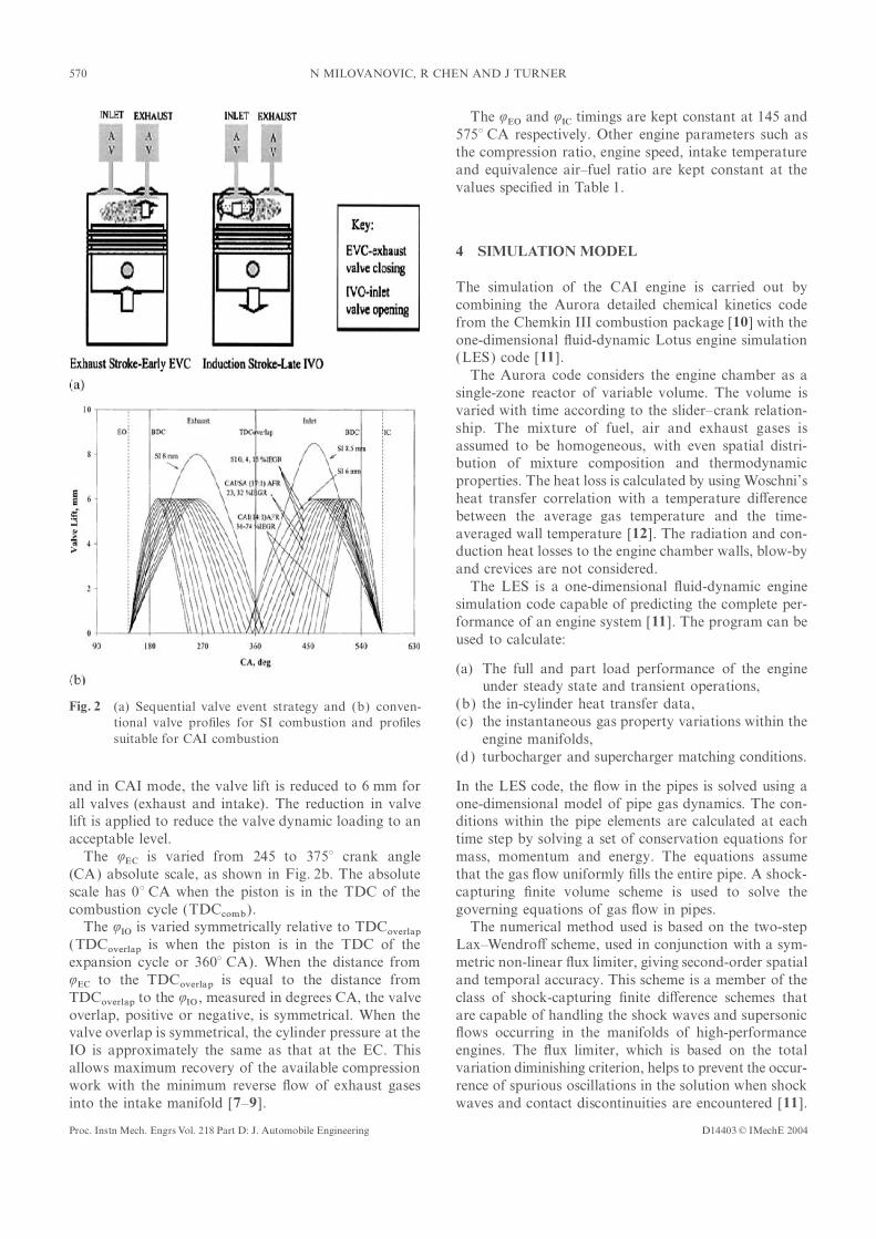
system 3.2 Valve events for CAI combustion
The technique used to initiate and to control CAI
combustion relies on the trapping of a predeterminedthe custom-made bottom end. Only the front cylinder
quantity of exhaust gases by closing the exhaust valvesof the head is operational. The water jacket uses a
relatively early in the exhaust stroke and by openingcombination of machined modi�cations and brackets.
the inlet valves relatively late in the intake stroke. TheUnnecessary water transfer ports are blanked o�. The
general principle can be seen in Fig. 2a.engine has a bespoke single-cylinder bottom end designed
The trapped exhaust gases are then compressed duringand developed by Lotus to allow either pure combustion
the �nal stage of the exhaust stroke. As the pistonwork or optical access versions to be built. The exhaust
descends on the intake stroke, the inlet valves are openedsystem used on the single-cylinder research engine was
and a fresh charge is drawn into the cylinder whicha standard one. The system was not modi�ed since the
is partially �lled with exhaust gases. At the end of theexhaust gases were trapped into the cylinder by using
intake stroke the inlet valves are closed and the mixturethe early exhaust valve closure event coupled with the late
of fresh charge and exhaust gas is then compressed ininlet valve opening event. In this way, a major amount
the next compression stroke. The CAI combustion occursof available IEGR was trapped inside the cylinder (up
as the mixture temperature increases in the �nal stage ofto 80 per cent) and the rest was discharged through the
the compression stroke. Once CAI has occurred, theexhaust system.
power stroke drives the piston down and the cycle isThe major engine speci�cations and test conditions
thus repeated. This is the sequential method. Anotherare shown in Table 1. A detailed description of the engine
method for achieving CAI combustion, the simultaneouscan be found in reference [6 ].
method, has also been derived, and detailed explanationsThe research FVVT system is �tted to allow the
can be found in references [6 ] and [7 ].variable valve timing strategy to be used to trap the
In order to trap the various quantities of IEGR andprede�ned quantity of IEGR. The open and closing
to obtain transition from conventional SI combustiontimings of each of four electrohydraulically driven valves
to CAI combustion, series of valve timings are used.
Figure 2b summarizes the valve timings and estimated
quantities of trapped IEGR.Table 1 Single-cylinder engine speci�cation and test conditionsTransition from SI to CAI mode is achieved by
Bore 80.5 mm increasing the negative valve overlap between the exhaustStroke 88.2 mm valve closure event, Q
EC, and inlet valve opening event,Swept volume 450 cm3
QIO , and by reducing the valve lift. The intake andCompression ratio 10.5
Speed å5000 r/min exhaust valve events are varied from a ‘normal’ valveLoad range 2–5 bar (i.m.e.p.) event with positive valve overlap (as for a typical four-Number of valves per cylinder 4
stroke SI engine) to a very early QEC coupled with aValve control ElectrohydraulicLotus AVT-FVVT system symmetrically very late QIO . With increase in the negative
Fuel injection Port fuelled valve overlap, a camless CAI engine goes from conven-Fuel Gasoline (95RON)
tional SI operation, through a transient period and intoEquivalence air–fuel ratio StoichiometricIntake temperature 25 °C CAI operation [6, 8 ]. Valve lifts of 8 mm for the exhaustInlet pressure Naturally aspirated valves and 8.5 mm for the inlet valves are used for theIEGR å80 vol %
SI mode. When the engine is operated in a transient
D14403 © IMechE 2004 Proc. Instn Mech. Engrs Vol. 218 Part D: J. Automobile Engineering
570 N MILOVANOVIC, R CHEN AND J TURNER
The QEO and Q
IC timings are kept constant at 145 and
575° CA respectively. Other engine parameters such as
the compression ratio, engine speed, intake temperature
and equivalence air–fuel ratio are kept constant at the
values speci�ed in Table 1.
4 SIMULATION MODEL
The simulation of the CAI engine is carried out by
combining the Aurora detailed chemical kinetics code
from the Chemkin III combustion package [10] with the
one-dimensional �uid-dynamic Lotus engine simulation
(LES) code [11].
The Aurora code considers the engine chamber as a
single-zone reactor of variable volume. The volume is
varied with time according to the slider–crank relation-
ship. The mixture of fuel, air and exhaust gases is
assumed to be homogeneous, with even spatial distri-
bution of mixture composition and thermodynamic
properties. The heat loss is calculated by using Woschni’s
heat transfer correlation with a temperature di�erence
between the average gas temperature and the time-
averaged wall temperature [12]. The radiation and con-
duction heat losses to the engine chamber walls, blow-by
and crevices are not considered.
The LES is a one-dimensional �uid-dynamic engine
simulation code capable of predicting the complete per-
formance of an engine system [11]. The program can be
used to calculate:
(a) The full and part load performance of the engine
under steady state and transient operations,
(b) the in-cylinder heat transfer data,Fig. 2 (a) Sequential valve event strategy and (b) conven-(c) the instantaneous gas property variations within thetional valve pro�les for SI combustion and pro�les
suitable for CAI combustion engine manifolds,
(d) turbocharger and supercharger matching conditions.
In the LES code, the �ow in the pipes is solved using aand in CAI mode, the valve lift is reduced to 6 mm for
all valves (exhaust and intake). The reduction in valve one-dimensional model of pipe gas dynamics. The con-
ditions within the pipe elements are calculated at eachlift is applied to reduce the valve dynamic loading to an
acceptable level. time step by solving a set of conservation equations for
mass, momentum and energy. The equations assumeThe QEC is varied from 245 to 375° crank angle
(CA) absolute scale, as shown in Fig. 2b. The absolute that the gas �ow uniformly �lls the entire pipe. A shock-
capturing �nite volume scheme is used to solve thescale has 0° CA when the piston is in the TDC of the
combustion cycle (TDCcomb). governing equations of gas �ow in pipes.
The numerical method used is based on the two-stepThe QIO is varied symmetrically relative to TDCoverlap
(TDCoverlap is when the piston is in the TDC of the Lax–Wendro� scheme, used in conjunction with a sym-
metric non-linear �ux limiter, giving second-order spatialexpansion cycle or 360° CA). When the distance from
QEC to the TDCoverlap is equal to the distance from and temporal accuracy. This scheme is a member of the
class of shock-capturing �nite di�erence schemes thatTDCoverlap to the QIO , measured in degrees CA, the valve
overlap, positive or negative, is symmetrical. When the are capable of handling the shock waves and supersonic
�ows occurring in the manifolds of high-performancevalve overlap is symmetrical, the cylinder pressure at the
IO is approximately the same as that at the EC. This engines. The �ux limiter, which is based on the total
variation diminishing criterion, helps to prevent the occur-allows maximum recovery of the available compression
work with the minimum reverse �ow of exhaust gases rence of spurious oscillations in the solution when shock
waves and contact discontinuities are encountered [11].into the intake manifold [7–9 ].
D14403 © IMechE 2004Proc. Instn Mech. Engrs Vol. 218 Part D: J. Automobile Engineering
571INFLUENCE OF VARIABLE VALVE TIMINGS ON THE GAS EXCHANGE PROCESS
The LES program allows the user to build a model of For simulation of gasoline fuel 95RON, a mixture of
isooctane and n-heptane fuels (95 vol % isooctane andthe entire engine by selecting engine components from a
toolbox and connecting them by pipe elements. 5 vol % n-heptane) is used. The detailed chemical kinetics
mechanism for a mixture of isooctane and n-heptaneThe simulation is started with the Aurora code which
calculates the compression (from IC), autoignition, com- fuel, which consists of 1087 species and 4392 reactions
with complete NOx
chemistry, has been developedbustion and expansion (until EO), with a time step of
1° CA. The initial values of the charge mixture at the IC in-house and validated successfully against the available
test data. The mechanism is able to predict autoignitionpoint, such as temperature, pressure and composition,
are assumed. At the end of the expansion stroke, the behaviour for various fuel research octane numbers
(RON ) at di�erent temperatures and pressures, and itcalculated data of the cylinder pressure, temperature and
exhaust gas composition are transferred to the LES code, is explained in detail in reference [18]. The cylinder wall,
piston and head are all assumed to be at a uniformwhich uses them as an input. The LES code performs
the calculation of the exhaust and intake strokes (from temperature of 500 K.
The calculated cylinder pressure history is comparedEO to the IC point—the gas exchange process), with the
same time step as the Aurora code. The data for the with the cylinder pressure history recorded in the test, and
results are presented in Fig. 3a. It can be seen that thecharge mixture temperature, pressure and composition
obtained at the end of intake strokes (IC point) are general shape of the experimental cylinder pressure curve
is well reproduced over the complete cycle. The peaktransferred back to the Aurora code and used as an input
for the new calculation cycle. The calculation continues cylinder pressure is overpredicted owing to assumptions
that the whole cylinder charge burns simultaneously anduntil di�erences between runs reach the convergence
criteria. completely and owing to the de�ciency of the single-zone
assumption in modelling the temperature gradient withinAurora is chosen owing to its ability to predict
accurately the autoignition of CAI combustion [13–15], the charge mixture. In a real engine, the charge mixture
inside the cylinder is not uniform in temperature andwhile the LES code is employed owing to its ability to
model the instantaneous charge mixture properties in the composition and a small portion of fuel captured in
crevices will not burn. Therefore, the pressure gradientengine manifolds.
after ignition will be lower. On the other hand, the
start of autoignition is predicted correctly. The pressure
pulses (pressure waves generated by the blowdown and
displacement processes) predicted by the LES code, at5 MODEL VALIDATIONthe start of the gas exchange process (the EO point),
are also consistent with the measured pulses. The com-The results obtained by using the simulation model are
validated against the experimental results. It was found parison of calculated and experimental values for several
global engine parameters is shown in Table 2.that at least 30 cycles have to be calculated to reach a
satisfactory degree of convergence with the experimental It can be seen that experimental values are generally
well matched within a di�erence of 10 per cent. Theresults. The engine speci�cation and conditions used in
the simulation were the same as those used in the experi- values of the engine parameters such as i.m.e.p.,
b.m.e.p., indicated power, volumetric e�ciency, mech-ment and summarized in Table 1 (e 10.5, engine speed
2000 r/min, bore×stroke 80.5×88.2 mm, 50 per cent anical e�ciency and b.s.f.c. are overpredicted on account
of previously mentioned assumptions that the wholeIEGR, gasoline fuel 95RON and stoichiometric equival-
ence air–fuel ratio). The charge mixture pressure, tem- charge burns simultaneously and completely. The tem-
perature in the exhaust manifold is matched within aperature and composition at the IC point were assumed
or estimated. The charge pressure was assumed to be di�erence of 1.1 per cent, while the di�erence for the
quantity of trapped IEGR is within 4 per cent. It is worth1 bar (naturally aspirated engine). The charge temper-
ature and composition were estimated from the amount emphasizing that the quantity of trapped IEGR in the
experiment was estimated since it could not be measured.of trapped exhaust gases obtained from the test and by
assuming the mixing of ideal gases. The detailed pro- The range of di�erences for the calculated engine para-
meters seems acceptable considering that the accuracycedure has been reported in references [9 ], [16 ] and [17].
The estimated charge temperature was 430 K and the of the experimental data is not exactly known. Usually
with a pressure transducer suited for a thermodynamicestimated composition was 50 per cent IEGR and 50 per
cent air/fuel charge. It is very important to be able to evaluation, i.m.e.p. can be determined with less than
3 per cent di�erence, but sometimes this can be up toestimate correctly the charge properties at IC, since it
is crucial for the accurate modelling of CAI process 10 per cent [9 ].
It is worth noting that, with the use of LES code forignition. The charge values at IC are instantaneous ones
and therefore di�cult to measure accurately. These values modelling the exhaust and induction process, the charge
properties at IC can be automatically calculated andgreatly depend on the �uid-dynamic and gas exchange
processes that take place from EO to IC. used as an input to the Aurora code. This is very useful
D14403 © IMechE 2004 Proc. Instn Mech. Engrs Vol. 218 Part D: J. Automobile Engineering

572 N MILOVANOVIC, R CHEN AND J TURNER
Fig. 3 Comparison of calculated and experimental values: (a) cylinder pressure histories; (b) exhaust gas
temperature; (c) i.m.e.p. and b.m.e.p.; (d) volumetric and mechanical e�ciencies; (e) b.s.f.c.
D14403 © IMechE 2004Proc. Instn Mech. Engrs Vol. 218 Part D: J. Automobile Engineering
573INFLUENCE OF VARIABLE VALVE TIMINGS ON THE GAS EXCHANGE PROCESS
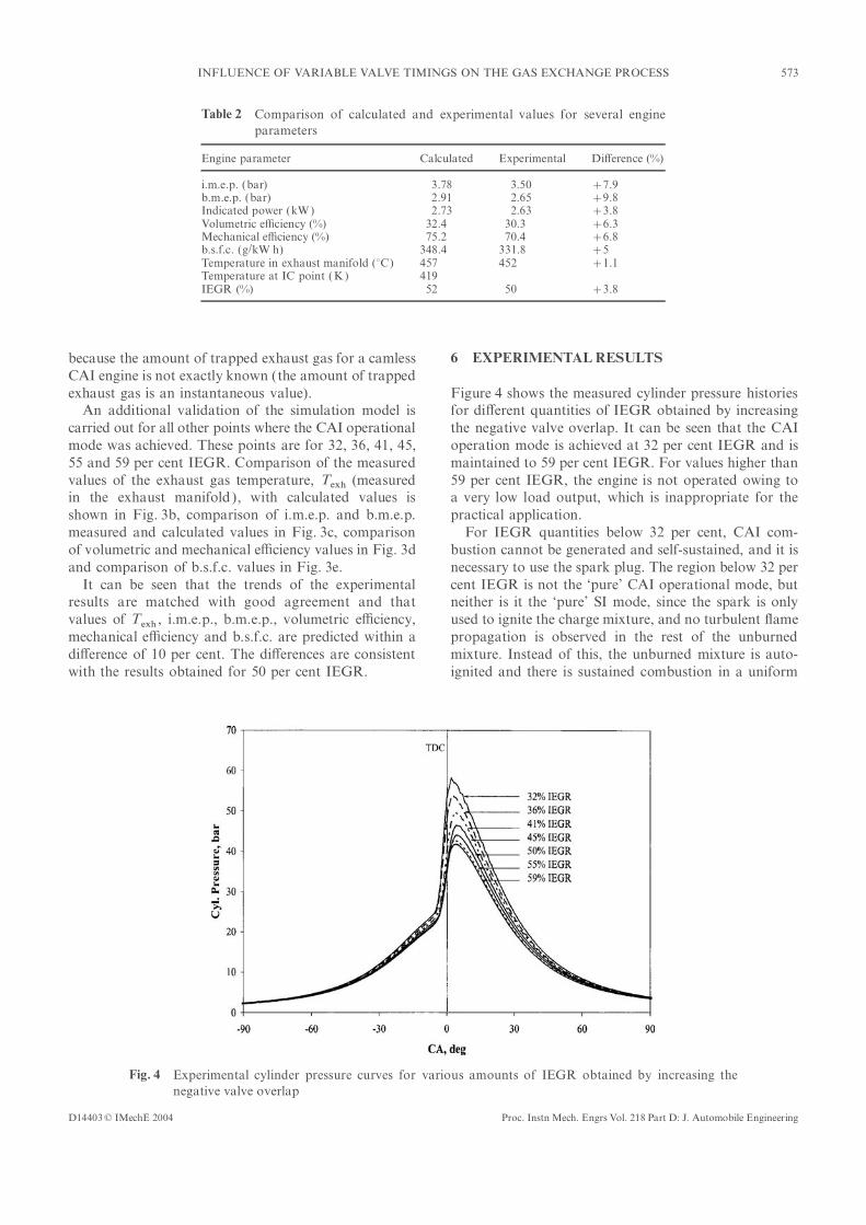
Table 2 Comparison of calculated and experimental values for several engine
parameters
Engine parameter Calculated Experimental Di�erence (%)
i.m.e.p. (bar) 3.78 3.50 +7.9b.m.e.p. (bar) 2.91 2.65 +9.8Indicated power (kW) 2.73 2.63 +3.8Volumetric e�ciency (%) 32.4 30.3 +6.3Mechanical e�ciency (%) 75.2 70.4 +6.8b.s.f.c. (g/kW h) 348.4 331.8 +5Temperature in exhaust manifold (°C) 457 452 +1.1Temperature at IC point (K) 419IEGR (%) 52 50 +3.8
because the amount of trapped exhaust gas for a camless 6 EXPERIMENTAL RESULTSCAI engine is not exactly known (the amount of trapped
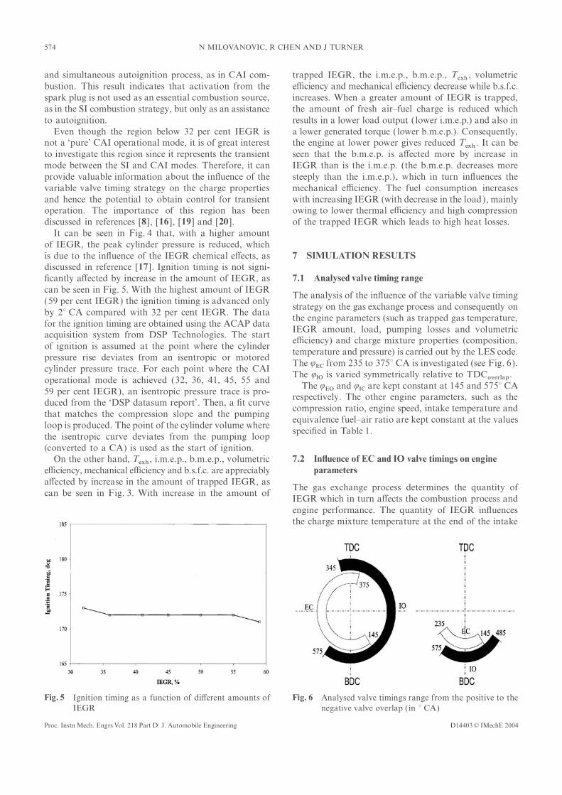
exhaust gas is an instantaneous value). Figure 4 shows the measured cylinder pressure histories
for di�erent quantities of IEGR obtained by increasingAn additional validation of the simulation model is
carried out for all other points where the CAI operational the negative valve overlap. It can be seen that the CAI
operation mode is achieved at 32 per cent IEGR and ismode was achieved. These points are for 32, 36, 41, 45,
55 and 59 per cent IEGR. Comparison of the measured maintained to 59 per cent IEGR. For values higher than
59 per cent IEGR, the engine is not operated owing tovalues of the exhaust gas temperature, Texh (measured
in the exhaust manifold ), with calculated values is a very low load output, which is inappropriate for the
practical application.shown in Fig. 3b, comparison of i.m.e.p. and b.m.e.p.
measured and calculated values in Fig. 3c, comparison For IEGR quantities below 32 per cent, CAI com-
bustion cannot be generated and self-sustained, and it isof volumetric and mechanical e�ciency values in Fig. 3d
and comparison of b.s.f.c. values in Fig. 3e. necessary to use the spark plug. The region below 32 per
cent IEGR is not the ‘pure’ CAI operational mode, butIt can be seen that the trends of the experimental
results are matched with good agreement and that neither is it the ‘pure’ SI mode, since the spark is only
used to ignite the charge mixture, and no turbulent �amevalues of Texh , i.m.e.p., b.m.e.p., volumetric e�ciency,
mechanical e�ciency and b.s.f.c. are predicted within a propagation is observed in the rest of the unburned
mixture. Instead of this, the unburned mixture is auto-di�erence of 10 per cent. The di�erences are consistent
with the results obtained for 50 per cent IEGR. ignited and there is sustained combustion in a uniform
Fig. 4 Experimental cylinder pressure curves for various amounts of IEGR obtained by increasing the
negative valve overlap
D14403 © IMechE 2004 Proc. Instn Mech. Engrs Vol. 218 Part D: J. Automobile Engineering
574 N MILOVANOVIC, R CHEN AND J TURNER
and simultaneous autoignition process, as in CAI com- trapped IEGR, the i.m.e.p., b.m.e.p., Texh , volumetric
e�ciency and mechanical e�ciency decrease while b.s.f.c.bustion. This result indicates that activation from the
spark plug is not used as an essential combustion source, increases. When a greater amount of IEGR is trapped,
the amount of fresh air–fuel charge is reduced whichas in the SI combustion strategy, but only as an assistance
to autoignition. results in a lower load output ( lower i.m.e.p.) and also in
a lower generated torque ( lower b.m.e.p.). Consequently,Even though the region below 32 per cent IEGR is
not a ‘pure’ CAI operational mode, it is of great interest the engine at lower power gives reduced Texh . It can be
seen that the b.m.e.p. is a�ected more by increase into investigate this region since it represents the transient
mode between the SI and CAI modes. Therefore, it can IEGR than is the i.m.e.p. (the b.m.e.p. decreases more
steeply than the i.m.e.p.), which in turn in�uences theprovide valuable information about the in�uence of the
variable valve timing strategy on the charge properties mechanical e�ciency. The fuel consumption increases
with increasing IEGR (with decrease in the load), mainlyand hence the potential to obtain control for transient
operation. The importance of this region has been owing to lower thermal e�ciency and high compression
of the trapped IEGR which leads to high heat losses.discussed in references [8 ], [16 ], [19] and [20 ].
It can be seen in Fig. 4 that, with a higher amount
of IEGR, the peak cylinder pressure is reduced, which
is due to the in�uence of the IEGR chemical e�ects, as 7 SIMULATION RESULTSdiscussed in reference [17]. Ignition timing is not signi-
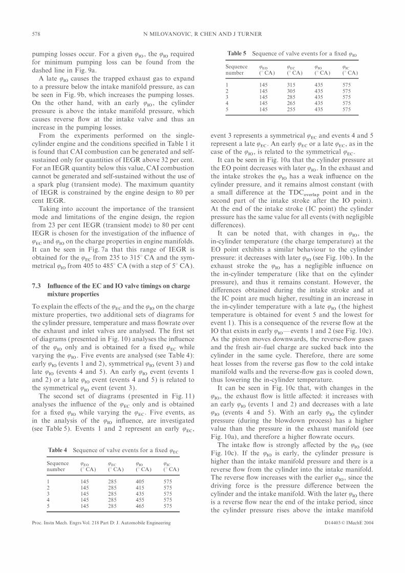
�cantly a�ected by increase in the amount of IEGR, as 7.1 Analysed valve timing rangecan be seen in Fig. 5. With the highest amount of IEGR
The analysis of the in�uence of the variable valve timing(59 per cent IEGR) the ignition timing is advanced only
strategy on the gas exchange process and consequently onby 2° CA compared with 32 per cent IEGR. The data
the engine parameters (such as trapped gas temperature,for the ignition timing are obtained using the ACAP data
IEGR amount, load, pumping losses and volumetricacquisition system from DSP Technologies. The start
e�ciency) and charge mixture properties (composition,of ignition is assumed at the point where the cylinder
temperature and pressure) is carried out by the LES code.pressure rise deviates from an isentropic or motored
The QEC from 235 to 375° CA is investigated (see Fig. 6).cylinder pressure trace. For each point where the CAI
The QIO is varied symmetrically relative to TDCoverlap.operational mode is achieved (32, 36, 41, 45, 55 and
The QEO and QIC are kept constant at 145 and 575° CA59 per cent IEGR), an isentropic pressure trace is pro-
respectively. The other engine parameters, such as theduced from the ‘DSP datasum report’. Then, a �t curve
compression ratio, engine speed, intake temperature andthat matches the compression slope and the pumping
equivalence fuel–air ratio are kept constant at the valuesloop is produced. The point of the cylinder volume where
speci�ed in Table 1.the isentropic curve deviates from the pumping loop
(converted to a CA) is used as the start of ignition.
On the other hand, Texh, i.m.e.p., b.m.e.p., volumetric 7.2 In�uence of EC and IO valve timings on engine
parameterse�ciency, mechanical e�ciency and b.s.f.c. are appreciably
a�ected by increase in the amount of trapped IEGR, asThe gas exchange process determines the quantity of
can be seen in Fig. 3. With increase in the amount ofIEGR which in turn a�ects the combustion process and
engine performance. The quantity of IEGR in�uences
the charge mixture temperature at the end of the intake
Fig. 5 Ignition timing as a function of di�erent amounts of Fig. 6 Analysed valve timings range from the positive to the
negative valve overlap (in ° CA)IEGR
D14403 © IMechE 2004Proc. Instn Mech. Engrs Vol. 218 Part D: J. Automobile Engineering

575INFLUENCE OF VARIABLE VALVE TIMINGS ON THE GAS EXCHANGE PROCESS
stroke (IC point) and therefore the ignition timing
and heat release rate. Also, the quantity of IEGR deter-
mines the amount of fresh charge and therefore a�ects
the volumetric e�ciency and load of the engine.
The changes in IEGR quantity with variations in
QEC and QIO are shown in Fig. 7a, the changes in i.m.e.p.
in Fig. 7b and the changes in volumetric e�ciency in
Fig. 7c.
It can be seen that the IEGR quantity, i.m.e.p. and
volumetric e�ciency are mainly in�uenced by the QEC.
The IEGR decreases with later EVC, because less exhaust
gas is trapped. Therefore, more fresh charge is intro-
duced, resulting in an increase in volumetric e�ciency
and i.m.e.p.
Overall, the QIO has considerably less in�uence on the
IEGR quantity, volumetric e�ciency and i.m.e.p., except
in the two isolated regions (‘islands’). These two ‘islands’
are for a very late QIO (from 445 to 485° CA) and for a
relatively early QIO (from 355 to 380° CA), while the Q
ECrange is from 250 to 275° CA. A very late QIO causes the
trapped exhaust gas to expand to a pressure below the
inlet manifold pressure which a�ects the IEGR quantity
and i.m.e.p. With a relatively early QIO , the cylinder
pressure is above the intake manifold pressure which
causes a reverse �ow (at the intake valve) and therefore
in�uences the IEGR quantity and i.m.e.p.
For understanding the physics of the gas exchange
process, additional diagrams of the cylinder pressure,
temperature and mass �owrate over the exhaust and
inlet valves are presented in Fig. 8. Four valve events
are analysed (see Table 3): the ‘normal’ valve event with
positive valve overlap (event 1), the event with the
biggest negative valve overlap—the earliest QEC coupled
with the latest QIO (event 4) and two events in-between
(events 2 and 3). The QIO is opened symmetrically.
It can be seen that the cylinder pressure, temperature
and mass �owrate over the exhaust and inlet valves are
closely related to the QEC and the QIO . For event 1 the
cylinder pressure at the EO point has the highest value
among the analysed events (see Fig. 8a), since the charge
mixture has the highest amount of fuel (the lowest IEGR
amount) which in turn produces the highest power
output (see Fig. 7a) and therefore the highest cylinder
pressure. With increase in the negative valve overlap,
the fuel amount in the charge decreases (the strength
of the charge mixture decreases), reducing the cylinder
pressure.
Table 3 Sequence of four di�erent valve events
Sequence QEO QEC QIO QICnumber (° CA) (° CA) (° CA) (° CA) Fig. 7 (a) IEGR quantity, (b) i.m.e.p. and (c) volumetric
e�ciency as a function of QEC and QIO1 145 375 345 5752 145 315 405 5753 145 275 445 5754 145 235 485 575
D14403 © IMechE 2004 Proc. Instn Mech. Engrs Vol. 218 Part D: J. Automobile Engineering
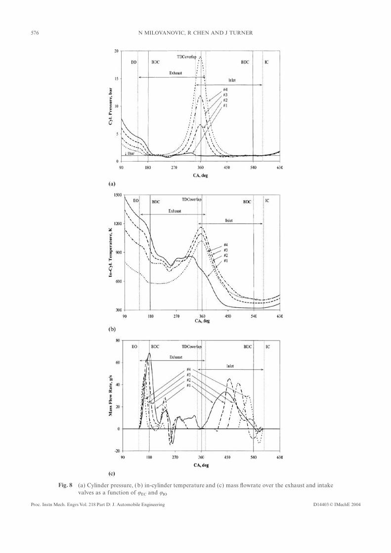
576 N MILOVANOVIC, R CHEN AND J TURNER
Fig. 8 (a) Cylinder pressure, (b) in-cylinder temperature and (c) mass �owrate over the exhaust and intake
valves as a function of QEC and QIOD14403 © IMechE 2004Proc. Instn Mech. Engrs Vol. 218 Part D: J. Automobile Engineering

577INFLUENCE OF VARIABLE VALVE TIMINGS ON THE GAS EXCHANGE PROCESS
However, the situation changes in the exhaust stroke pressure (see Fig. 8a). This is an inevitable consequence
of the QIC chosen to take advantage of the ram e�ect at(when the transition from blowdown to displacement
high speeds [even though the experiment and simulationoccurs), and the cylinder pressure reaches its highestwere performed for a speed of 2000 r/min, in ongoingvalue for event 4 (the weakest mixture) and its lowest(and future) investigations it is planned to cover a speedvalue for event 1 (the strongest mixture). This is mainlyrange up to 7000 r/min].in�uenced by the QEC , as it occurs increasingly early with
The velocity obtained at the exhaust valve (duringincreasing amount of compression. At the end of thethe exhaust process) varies from #150 m/s (event 1) tointake stroke the cylinder pressure has approximately#70 m/s (event 4). The velocity at the intake valvethe same value for all events (with negligible di�erences).(during the intake process) is in the range from #45 m/sThe in-cylinder temperature (see Fig. 8b) has a similar(event 1) to #65 m/s (event 4).behaviour at the EO point to the cylinder pressure: it
The in�uence of the QEC and QIO timing on the enginedecreases with increase in the negative valve overlappumping losses is shown in Fig. 9a. The pumping losses(with decrease in the amount of fuel in the chargeare evaluated from the i.m.e.p. for the exhaust andmixture), and therefore the highest value is reached forintake strokes.event 1 and the lowest value for event 4. On the other
It can be seen that the minimum pumping losses takehand, the in-cylinder temperature (the charge temper-place for the symmetrical QEC and QIO . When the QIO isature) exhibits di�erent behaviour in the exhaust stroke.opened symmetrically, the in-cylinder pressure is near orAt TDCoverlap it reaches its minimum value for event 1equal to the intake manifold pressure and the minimumand its maximum value for event 3 (in the order
3>2>4>1 from the highest to the lowest value), while
at the IC point the order is changed to 4>3>2>1.
This complex behaviour is most probably in�uenced by
many factors such as the boundary conditions (the state
at EO), the pressure changes caused by the piston move-
ment and indirectly by the valve movement, the amount
of compression heating and the IEGR quantity. Detailed
analysis of the cylinder temperature at characteristic
points will be presented in section 7.4
It can be seen that the mass �owrates over the exhaust
and inlet valves, presented in Fig. 8c, are in�uenced by
the QEC and the QIO . As the QEC occurs early (and the QIOsymmetrically late), the exhaust and the intake �ows
decrease. Decrease in the mass �owrate over the exhaust
and intake valves, together with a shorter duration of
the exhaust event (the period between EO and the EC)
and the intake event (the period between IO and IC ),
reduces the mass of exhaust gases exhaled and the mass
of fresh fuel–air charge inhaled. As a result, the engine
parameters are a�ected (see Fig. 7).
It can be noted that the exhaust �ow reaches its �rst
maximum at the valve maximum open point (MOP).
The second maximum occurs later and is a consequence
of the waves generated by the piston and the valve
opposite movements. The exhaust process begins with
EO, and, until about BDC, the exhaust gases are dis-
charged owing to the pressure di�erence between the
cylinder and the exhaust system. After BDC, the cylinder
is cleaned by the piston as it moves towards TDC. The
reverse �ow at the exhaust valve (events 1, 2 and 3)
occurs because the cylinder pressure is lower than the
pressure in the exhaust manifold.
It can be noted that the intake �ow, for all events,
experiences a reverse �ow near the end of the intake
period, since the inlet valve is closed after the start of
the compression stroke (IC at 575° CA) and therefore Fig. 9 (a) Pumping losses and (b) cylinder pressure values at
the IO point as a function of QEC and QIOthe cylinder pressure rises above the intake manifold
D14403 © IMechE 2004 Proc. Instn Mech. Engrs Vol. 218 Part D: J. Automobile Engineering
578 N MILOVANOVIC, R CHEN AND J TURNER
Table 5 Sequence of valve events for a �xed QIOpumping losses occur. For a given QIO , the Q
IO required
for minimum pumping loss can be found from theSequence QEO QEC QIO QICdashed line in Fig. 9a. number (° CA) (° CA) (° CA) (° CA)
A late QIO causes the trapped exhaust gas to expand1 145 315 435 575to a pressure below the intake manifold pressure, as can2 145 305 435 575
be seen in Fig. 9b, which increases the pumping losses. 3 145 285 435 5754 145 265 435 575On the other hand, with an early Q
IO , the cylinder5 145 255 435 575pressure is above the intake manifold pressure, which
causes reverse �ow at the intake valve and thus an
increase in the pumping losses.
From the experiments performed on the single- event 3 represents a symmetrical QEC and events 4 and 5
represent a late QEC . An early QEC or a late QEC, as in thecylinder engine and the conditions speci�ed in Table 1 it
is found that CAI combustion can be generated and self- case of the QIO , is related to the symmetrical Q
EC.
It can be seen in Fig. 10a that the cylinder pressure atsustained only for quantities of IEGR above 32 per cent.
For an IEGR quantity below this value, CAI combustion the EO point decreases with later QIO . In the exhaust and
the intake strokes the QIO has a weak in�uence on thecannot be generated and self-sustained without the use of
a spark plug (transient mode). The maximum quantity cylinder pressure, and it remains almost constant (with
a small di�erence at the TDCoverlap point and in theof IEGR is constrained by the engine design to 80 per
cent IEGR. second part of the intake stroke after the IO point).
At the end of the intake stroke (IC point) the cylinderTaking into account the importance of the transient
mode and limitations of the engine design, the region pressure has the same value for all events (with negligible
di�erences).from 23 per cent IEGR (transient mode) to 80 per cent
IEGR is chosen for the investigation of the in�uence of It can be noted that, with changes in QIO , the
in-cylinder temperature (the charge temperature) at theQEC and Q
IO on the charge properties in engine manifolds.
It can be seen in Fig. 7a that this range of IEGR is EO point exhibits a similar behaviour to the cylinder
pressure: it decreases with later QIO (see Fig. 10b). In theobtained for the QEC from 235 to 315° CA and the sym-
metrical QIO from 405 to 485° CA (with a step of 5° CA). exhaust stroke the QIO has a negligible in�uence on
the in-cylinder temperature ( like that on the cylinder
pressure), and thus it remains constant. However, the7.3 In�uence of the EC and IO valve timings on chargedi�erences obtained during the intake stroke and atmixture propertiesthe IC point are much higher, resulting in an increase in
the in-cylinder temperature with a late QIO (the highestTo explain the e�ects of the QEC and the QIO on the charge
mixture properties, two additional sets of diagrams for temperature is obtained for event 5 and the lowest for
event 1). This is a consequence of the reverse �ow at thethe cylinder pressure, temperature and mass �owrate over
the exhaust and inlet valves are analysed. The �rst set IO that exists in early QIO—events 1 and 2 (see Fig. 10c).
As the piston moves downwards, the reverse-�ow gasesof diagrams (presented in Fig. 10) analyses the in�uence
of the QIO only and is obtained for a �xed QEC while and the fresh air–fuel charge are sucked back into the
cylinder in the same cycle. Therefore, there are somevarying the QIO . Five events are analysed (see Table 4):
early QIO (events 1 and 2), symmetrical QIO (event 3) and heat losses from the reverse gas �ow to the cold intake
manifold walls and the reverse-�ow gas is cooled down,late QIO (events 4 and 5). An early QIO event (events 1
and 2) or a late QIO event (events 4 and 5) is related to thus lowering the in-cylinder temperature.
It can be seen in Fig. 10c that, with changes in thethe symmetrical QIO event (event 3).
The second set of diagrams (presented in Fig. 11) QIO , the exhaust �ow is little a�ected: it increases with
an early QIO (events 1 and 2) and decreases with a lateanalyses the in�uence of the QEC only and is obtained
for a �xed QIO while varying the QEC . Five events, as QIO (events 4 and 5). With an early QIO the cylinder
pressure (during the blowdown process) has a higherin the analysis of the QIO in�uence, are investigated
(see Table 5). Events 1 and 2 represent an early QEC, value than the pressure in the exhaust manifold (see
Fig. 10a), and therefore a higher �owrate occurs.
The intake �ow is strongly a�ected by the QIO (seeTable 4 Sequence of valve events for a �xed QEC Fig. 10c). If the QIO is early, the cylinder pressure is
higher than the intake manifold pressure and there is aSequence QEO QEC QIO QICnumber (° CA) (° CA) (° CA) (° CA) reverse �ow from the cylinder into the intake manifold.
The reverse �ow increases with the earlier QIO , since the
1 145 285 405 575driving force is the pressure di�erence between the2 145 285 415 575
3 145 285 435 575 cylinder and the intake manifold. With the later QIO there4 145 285 455 575 is a reverse �ow near the end of the intake period, since5 145 285 465 575
the cylinder pressure rises above the intake manifold
D14403 © IMechE 2004Proc. Instn Mech. Engrs Vol. 218 Part D: J. Automobile Engineering

579INFLUENCE OF VARIABLE VALVE TIMINGS ON THE GAS EXCHANGE PROCESS
Fig. 10 (a) Cylinder pressure, (b) in-cylinder temperature and (c) mass �owrate over the exhaust and intake
valves as a function of QIO (QEC �xed at 385° CA)
D14403 © IMechE 2004 Proc. Instn Mech. Engrs Vol. 218 Part D: J. Automobile Engineering

580 N MILOVANOVIC, R CHEN AND J TURNER
Fig. 11 (a) Cylinder pressure, (b) in-cylinder temperature and (c) mass �owrate over the exhaust and intake
valves as a function of QEC (QIO �xed at 435° CA)
D14403 © IMechE 2004Proc. Instn Mech. Engrs Vol. 218 Part D: J. Automobile Engineering
581INFLUENCE OF VARIABLE VALVE TIMINGS ON THE GAS EXCHANGE PROCESS
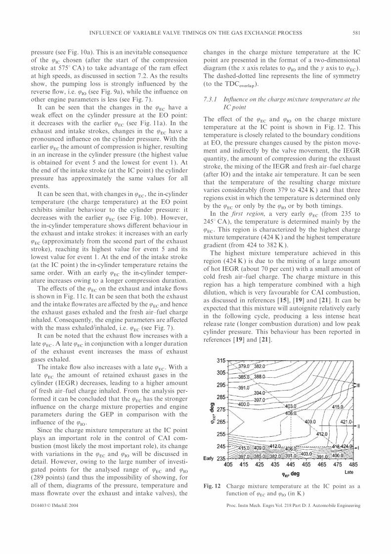
pressure (see Fig. 10a). This is an inevitable consequence changes in the charge mixture temperature at the IC
point are presented in the format of a two-dimensionalof the QIC chosen (after the start of the compression
stroke at 575° CA) to take advantage of the ram e�ect diagram (the x axis relates to QIO and the y axis to QEC).
The dashed-dotted line represents the line of symmetryat high speeds, as discussed in section 7.2. As the results
show, the pumping loss is strongly in�uenced by the (to the TDCoverlap).
reverse �ow, i.e. QIO (see Fig. 9a), while the in�uence on
other engine parameters is less (see Fig. 7). 7.3.1 In�uence on the charge mixture temperature at the
IC pointIt can be seen that the changes in the QEC have a
weak e�ect on the cylinder pressure at the EO point:The e�ect of the QEC and QIO on the charge mixture
it decreases with the earlier QEC (see Fig. 11a). In thetemperature at the IC point is shown in Fig. 12. This
exhaust and intake strokes, changes in the QEC have atemperature is closely related to the boundary conditions
pronounced in�uence on the cylinder pressure. With theat EO, the pressure changes caused by the piston move-
earlier QEC the amount of compression is higher, resulting
ment and indirectly by the valve movement, the IEGRin an increase in the cylinder pressure (the highest value
quantity, the amount of compression during the exhaustis obtained for event 5 and the lowest for event 1). At
stroke, the mixing of the IEGR and fresh air–fuel chargethe end of the intake stroke (at the IC point) the cylinder
(after IO) and the intake air temperature. It can be seenpressure has approximately the same values for all
that the temperature of the resulting charge mixtureevents.
varies considerably (from 379 to 424 K) and that threeIt can be seen that, with changes in Q
EC , the in-cylinderregions exist in which the temperature is determined only
temperature (the charge temperature) at the EO pointby the QEC or only by the QIO or by both timings.
exhibits similar behaviour to the cylinder pressure: itIn the �rst region, a very early QEC (from 235 to
decreases with the earlier QEC (see Fig. 10b). However,245° CA), the temperature is determined mainly by the
the in-cylinder temperature shows di�erent behaviour inQEC . This region is characterized by the highest charge
the exhaust and intake strokes: it increases with an earlymixture temperature (424 K) and the highest temperature
QEC (approximately from the second part of the exhaust
gradient (from 424 to 382 K).stroke), reaching its highest value for event 5 and its
The highest mixture temperature achieved in thislowest value for event 1. At the end of the intake stroke
region (424 K) is due to the mixing of a large amount(at the IC point) the in-cylinder temperature retains the
of hot IEGR (about 70 per cent) with a small amount ofsame order. With an early QEC the in-cylinder temper-
cold fresh air–fuel charge. The charge mixture in thisature increases owing to a longer compression duration.
region has a high temperature combined with a highThe e�ects of the QEC on the exhaust and intake �ows
dilution, which is very favourable for CAI combustion,is shown in Fig. 11c. It can be seen that both the exhaust
as discussed in references [15], [19] and [21]. It can beand the intake �owrates are a�ected by the QEC and hence
expected that this mixture will autoignite relatively earlythe exhaust gases exhaled and the fresh air–fuel charge
in the following cycle, producing a less intense heatinhaled. Consequently, the engine parameters are a�ected
release rate ( longer combustion duration) and low peakwith the mass exhaled/inhaled, i.e. Q
EC (see Fig. 7).cylinder pressure. This behaviour has been reported in
It can be noted that the exhaust �ow increases with areferences [19] and [21].
late QEC . A late QEC in conjunction with a longer duration
of the exhaust event increases the mass of exhaust
gases exhaled.
The intake �ow also increases with a late QEC . With a
late QEC the amount of retained exhaust gases in the
cylinder (IEGR) decreases, leading to a higher amount
of fresh air–fuel charge inhaled. From the analysis per-
formed it can be concluded that the QEC has the stronger
in�uence on the charge mixture properties and engine
parameters during the GEP in comparison with the
in�uence of the QIO .
Since the charge mixture temperature at the IC point
plays an important role in the control of CAI com-
bustion (most likely the most important role), its change
with variations in the QEC and QIO will be discussed in
detail. However, owing to the large number of investi-
gated points for the analysed range of QEC and QIO(289 points) (and thus the impossibility of showing, for
all of them, diagrams of the pressure, temperature and Fig. 12 Charge mixture temperature at the IC point as a
function of QEC and QIO (in K )mass �owrate over the exhaust and intake valves), the
D14403 © IMechE 2004 Proc. Instn Mech. Engrs Vol. 218 Part D: J. Automobile Engineering
582 N MILOVANOVIC, R CHEN AND J TURNER
The highest temperature gradient in this region is formed by Koopmans and Denbratt [8 ] it was found that
QEO and Q
IC have a minor in�uence on the gas exchangemainly the consequence of a signi�cant temperature
di�erence obtained during the exhaust stroke (during the process in a CAI engine. The QEO has the major in�uence
on pressure waves generated by the blowdown andcompression of the IEGR) and the existence of reverse
�ow (at the intake valve) at an asymmetrical QIO (see displacement processes. This result is in agreement with
the test results reported in reference [9 ]. Nevertheless,Figs 10b and c respectively).
The temperature in the second region (QEC from 245 the pressure waves may have an in�uence on the IEGR
quantity trapped at the EC point, but this in�uence isto 275° CA and QIO from 445 to 485° CA) is primarily
in�uenced by the QIO . The temperature in this region negligible in comparison with the in�uence of the QIOand QEC [19].changes from 421 to 406 K which is considerably lower
in comparison with the change in the �rst region. Also, The QIC has a very low impact on the engine para-
meters as it mainly in�uences the e�ective displacementit can be noted that the temperature gradient in this
region is considerably lower than that in the �rst region. volume and e�ective compression ratio. This result
is also in agreement with the test results reported inIn the second region the IEGR quantity is nearly
constant (#40 per cent) (see Fig. 7a), and therefore the reference [9 ].
mixing and gas exchange processes are mainly deter-
mined by the amount of fresh charge, i.e. by QIO timing.
A low variation in charge mixture temperature is
probably in�uenced by the QIO , i.e. by the non-existence 8 CONCLUSIONS
of reverse �ow (at the intake valve), at the beginning of
the intake process, for a late QIO . The mixture in this The in�uence of the variable valve timing strategy on
the gas exchange process in a CAI engine fuelled withregion will be expected to autoignite later than the
mixture in the �rst region and to produce a higher heat standard gasoline fuel (95RON) has been analysed.
The analysis was performed by the experimental andrelease rate and peak cylinder pressure. This observation
has been reported in references [19] and [21]. modelling approach. A single-cylinder research engine
equipped with a fully variable valvetrain (FVVT) systemThe rest of the map is the third region where the tem-
perature is a�ected by both QEC and QIO . The temperature was used for the experimental study. A combined code
consisting of a detailed chemical kinetics code andof the resulting mixture in this region varies from 415
to 379 K and is determined by a relatively low amount one-dimensional �uid dynamics code was used for the
modelling study.of hot IEGR and a relatively high amount of cold fresh
air–fuel charge. The existence of a relatively high tem- The results obtained indicate that the variable
valve timing strategy has a strong in�uence on the gasperature gradient (from 415 to 379 K) for the QEC from
275 to 315° CA and the QIO from 405 to 485° CA is exchange process, which in turn has a signi�cant e�ect
on the engine parameters and charge properties andmainly due to the in�uence of temperature variations in
IEGR (caused during the compression process of IEGR hence on the CAI combustion. The QEC has the strongest
in�uence, followed by the QIO , while Q
EO and QIC have ain the exhaust stroke) and less due to the in�uence of
reverse IEGR �ow (at the intake valve). On the other minor in�uence.
The QEC primarily determines the IEGR quantityhand, a relatively small temperature gradient (from 403
to 379 K) for the QEC from 245 to 275° CA and the and consequently the amount of fresh charge and there-
fore in�uences the engine load, indicated power andQIO from 405 to 445° CA is probably due to the larger
in�uence of the reverse �ow than that of the temperature volumetric e�ciency. Furthermore, the IEGR quantity
(the QEC) a�ects the charge mixture composition, tem-variations in IEGR.
A relatively low mixture temperature and small IEGR perature and pressure at the IC point and therefore the
autoignition timing and further combustion process, andquantity in the third region may cause mixture auto-
ignition not to occur and require a spark plug to be used hence the control of the CAI combustion.
The in�uence of QIO on engine parameters and controlto initiate the autoignition. The dilution of the resulting
charge and the temperature rise from the spark ignition of CAI combustion is less pronounced. The QIO mainly
in�uences the pumping losses and reverse �ow of thecombustion will be high enough to trigger the auto-
ignition in the remaining unburned mixture and to sus- IEGR at the intake valve.
The in�uence of QEO and QIC on the engine parameterstain CAI combustion in the way explained in section 6.
and charge mixture properties is negligible.
It can be concluded that the use of the variable valve7.4 In�uence of the EO and IC valve timings on enginetiming strategy has the potential to control the engineparameters and charge propertiesparameters and charge properties at the IC point, and
hence CAI combustion.From the test results obtained using the single-cylinder
research engine equipped with the FVVT system Along with the gas exchange process, the mixing pro-
cess that takes place between the IO event and the IC(explained in section 3) and from the experiments per-
D14403 © IMechE 2004Proc. Instn Mech. Engrs Vol. 218 Part D: J. Automobile Engineering

583INFLUENCE OF VARIABLE VALVE TIMINGS ON THE GAS EXCHANGE PROCESS
the analysis of gas-phase chemical and plasma kinetics.event may in�uence the engine parameters and chargeReport SAND96-8216, Sandia National Laboratories,properties. The mixing process will be studied in futureLivermore, California, 1996.research, and the results will be published elsewhere.
11 Lotus Engine Simulation (LES) Code Manual, 2001 (Lotus
Cars Company Limited, Hethel, Norfolk).
12 Woschini, G. Universally applicable equation for the
instantaneous heat transfer coe�cient in the internal com-
bustion engine. SAE paper 670931, 1967.REFERENCES 13 Ogink, R. and Golovitchev, V. Gasoline HCCI modeling:
computer program combining detailed chemistry and gas1 Onishi, S., Jo, S. H., Shoda, K., Jo, P. D. and Kato, S. exchange process. SAE paper 2001-01-3614, 2001.
Thermo-atmosphere combustion (ATAC)—a new com- 14 Westbrook, C. Chemical kinetics of hydrocarbon ignitionbustion process for internal combustion engines. SAE in practical combustion systems. In Proceedings of 28thpaper 790501, 1979. Combustion Symposium, Edinburgh, July 2000, Plenary
2 Noguchi, M., Tanaka, Y., Tanaka, T. and Takeuchi, Y. Lecture.A study on gasoline engine combustion by observation of 15 Chen, R., Milovanovic, N. and Law, D. A computationalintermediate reactive products during combustion. SAE study on the ignition timing of HCCI combustion in ICpaper 790840, 1979. engine fuelled with methane. In Proceedings of 2002 Spring
3 Hultqvist, A., Engdar, U., Johansson, B. and Klingmann, J. Technical Meeting of the Combustion Institute, CanadianReaction boundary layers in homogeneous charge com- Section, Windsor, Canada, May 2001, paper 53, pp. 158–163pression ignition (HCCI ) engine. SAE paper 2001-01-1032, (Canadian Section of The Combustion Institute).2001. 16 Chen, R., Milovanovic, N., Turner, J. and Blundell, D.
4 Hultqvist, A., Christensen, M., Johansson, B., Richter, M., Thermal e�ect of internal gas recirculation on controlledNygren, J., Hult, J. and Alden, M. The HCCI combustion auto ignition. SAE paper 2003-01-0750, 2003.process in a single cycle–high fuel tracer LIF and chemi- 17 Chen, R. and Milovanovic, N. A computational study intoluminescence imaging. SAE paper 2002-01-0424, 2002. the e�ect of exhaust gas recycling on homogeneous charge
5 Milovanovic, N. and Chen, R. A review of experimental and compression ignition combustion in internal combustionsimulation studies on controlled auto-ignition combustion. engine fuelled with methane. Int. J. Thermal Sci., 2002,SAE paper 2001-01-1890, 2001. 41, 805–813.
6 Law, D., Kemp, D., Allen, J., Kirkpartick, G. and 18 Milovanovic, N., Chen, R., Law, D. and Turner, J.Copland, T. Controlled combustion in an IC-engine with a Homogeneous charge compression ignition combustionfully variable valve train. SAE paper 2000-01-0251, 2000. and fuel composition. In Proceeding of 17th Internal
7 Turner, J., Blundell, D., Bassett, M., Pearson, R. and Combustion Engine Symposium, Tokyo, October 2002,Chen, R. The impact on engine performance of controlled paper 20026075, pp. 361–364 (JSAE).auto ignition versus spark ignition with two methods 19 Koopmans, L., Backlund, O. and Denbratt, I. Cycle to cycleof load control. In Proceedings of GPC 2002 Global variations: their in�uence on cycle resolved gas temperaturePowertrain Congress, Michigan, September 2002. and unburned hydrocarbons from a camless gasoline com-
8 Koopmans, L. and Denbratt, I. A four stroke camless pression ignition engine. SAE paper 2002-91-0110, 2002.engine, operated in homogeneous charge compression 20 Koopmans, L., Strom, H., Lundgren, S., Backlund, O. andignition mode with commercial gasoline. SAE paper Denbratt, I. Demonstrating a SI-HCCI-SI mode change on2001-01-3610, 2001. a Volvo 5-cylinder electronic valve control engine. SAE
9 Heywood, J. B. Internal Combustion Engine Fundamentals, paper 2003-01-0753, 2003.1988 (McGraw-Hill Book Company). 21 Zhao, H., Li, J., Ma, T. and Ladommatos, N. Performance
10 Kee, R. J., Rupley, F. M., Meeks, E. and Miller, J. A. and analysis of a 4-stroke multi-cylinder gasoline engine
with CAI combustion. SAE paper 2002-01-0420, 2002.CHEMKIN III: a Fortran chemical kinetics package for
D14403 © IMechE 2004 Proc. Instn Mech. Engrs Vol. 218 Part D: J. Automobile Engineering