influence of heat treatment parameters, · pdf file3309 was utilized for coating samples of...
TRANSCRIPT

1
Iranian Journal of Materials Science & Engineering Vol. 10, Number 2, June 2013
1. INTRODUCTION
Coatings applied by flame spraying techniquehas found a great deal of applications in variousindustries when highly aggressive environmentsare involved ,since a wide range of materialshave the potential to be used in thermal sprayingprocesses [1-4]. In particular case where highresistance to corrosion and wear are required, selfdiffusion nickel base alloys are usually used asthe main coating ingredients [5-8]. Among thesealloys, NiCrBSi alloy has one of the highestapplications as an overlay coating material [9-11].
Bonding strength of typical flame sprayedcoating contains 10-20% porosities within itsmicrostructure is usually weak. Applications ofvarious heat treatment cycles on the coatedsamples can reduce the amounts of porosities to0.3-5% and strengthen the bonding between thesplats and between the coating and the substrate.The holding time and the amount of temperatureutilized for heat treatment of sprayed coatedsamples are very crucial for the quality of thefinal coating microstructure and its tribological
properties [1, 5, and 11].There are published literatures on several
mechanical properties [4-6 and 11-12] ofNiCrBSi coatings produced by varioustechniques, but subjected to similar heattreatment cycles. These articles compares themechanical behaviour of this type of coating thatproduced by different techniques, however thepresent research compares some of themechanical properties of the coatings producedby single technique subjected to various heattreatment cycles. Wear and hardness behaviors ofNiCrBSi coatings applied by flame sprayingtechnique and subjected to various heattreatments were investigated and the heattreatment conditions led to optimum wearresistance and maximum microhardness valuehas been established. 2. EXPERIMENTAL PROCEDURE
NiCrBSi powder with merchandise code PE3309 was utilized for coating samples of CK45carbon steel. Chemical positions of both powderused for coating and the substrate are presented in
Abstract:The objectives of this research were to find an economical way of reducing porosities in the microstructureof coatings deposited by flame spraying technique on CK45 steel and also trying to increase their cohesive strength tothe substrate, so that the overall wear properties of this type of coating can be improved. So several specimens fromthis steel coated with NiCrBSi powder under specific conditions were subjected to various furnace heat treatment at1000, 1025, 1050, 1075 and 1100 °C, each for periods of 5, 10 and 15 minute before cooling them in air. Tribologicalproperties of treated coatings were evaluated by pin on disc method. The results show the highest wear resistance andmicrohardness values observed in one of the sample was due to lower amount of porosity and higher amount of veryfine Cr2Ni3B6 particles precipitated homogeneously throughout its microstructure during specific heat treatment.
Keywords: NiCrBSi coatings, Flame spraying, Coating, Heat treatment, CK45, Wear, Microstructure, Microhardness,Pin on Disc
INFLUENCE OF HEAT TREATMENT PARAMETERS,TEMPERATURE AND TIME, ON WEAR AND MICROHARDNESSOF NICRBSI FLAME SPRAYED COATINGS APPLIED ON CK45SUBSTRATESH. Arabi1,2 *, S. Rastegari2, V. Ramezani2 and Z. Valefi3* [email protected]: January 2013 Accepted: June 2013
1 Center of Excellence for High Temperature Alloys Technology, Iran University of Science and Technology,IUST, Tehran, Iran.2 School of Metallurgy and Materials Engineering, Iran University of Science and Technology, Tehran, Iran.3 School of metallurgy and materials engineering, Tehran University, Tehran, Iran.

2
Table 1. The powder has a spherical morphologywith a mean diameter of 33 µm. The steelsubstrates were in the form of disc with a thicknessof 10 mm and diameter of 25 mm. Table 2 presentsthe constant conditions used for flame spraying.The spraying procedure was performed in such a
way that to get the coating thickness of all thespecimens within the range of 250-300 µm. Thecoated samples were treated at 1000, 1025, 1050,1075 and 1100 °C, each for periods of 5, 10 and 15minutes before cooled them in air. The coatedsamples were coded according to Table 3.
H. Arabi, S. Rastegari, V. Ramezani and Z. Valefi
Weight (%) NiCrBSi powder CK45 substrate
Ni Balance ≤ 0.40 Cr 15.70 ≤ 0.40 Fe 4.08 Balance C 0.81 0.42 - 0.50 Si 4.27 ≤ 0.40 B 3.35 -
Mn - 0.5 – 0.8 P - 0.035 S - 0.035
Mo - ≤ 0.10
Table 1. Chemical compositions of NiCrBSi powder and substrate steel
amountParameter
/hm30.93Acetylene feed rate KPa100Acetylene pressure
/hm 3 1.7Oxygen feed rate KPa170Oxygen pressure
mm/sec 85 Torch X-axes motion
speed mm/sec 25 Torch Y-axes motion
speed
Table 2. Constant Parameters used for coating
Heat treatment cycle
°C, min, AC*
Sample Code Heat treatment cycle
°C, min, AC*
Sample
Code
1000, 5, AC 00-S-5 1050, 15, AC 50-S-15
1000, 10, AC 00-S-10 1075, 5, AC 75-S-5
1000, 15, AC 00-S-15 1075, 10, AC 75-S-10
. 1025, 5, AC 25-S-5 1075, 15, AC 75-S-15
1025, 10, AC 25-S-10 1100, 5, AC 100-S-5
1025, 15, AC 25-S-15 1100, 10, AC 100-S-10
1050, 5, AC 50-S-5 1100, 15, AC 100-S-15
1050, 10, AC 50-S-10
* Air Cooled
Table 3. Codes of the samples heat treated at various temperatures and times
3
Iranian Journal of Materials Science & Engineering Vol. 10, Number 2, June 2013
Tribological evaluations of heat treatedcoatings were carried out by pin on discapparatus according to ASTM G99-95 standard.Cylindrical pins with a diameter of 4mm made ofmartensitic steel (HVN=650) were used. Thediscs were the coated samples under study. Thenormal load applied was 80N; the rotation speedof pin on disc and the total sliding distance were0.133 m/s and 500m respectively. The sampleswere cleaned with acetone and dried before andafter wear test; then weighted and the differencebetween their weights evaluated as wearresistance parameter. The shapes of worn tracesand debris were evaluated by SEM. Finallymicrohardness measurements were carried out onthe coating surfaces and coating/substrate crosssection. The load and the loading period in thistest were 100gf and 15 sec respectively.3. RESULTS AND DISCUSSION
3. 1. Wear
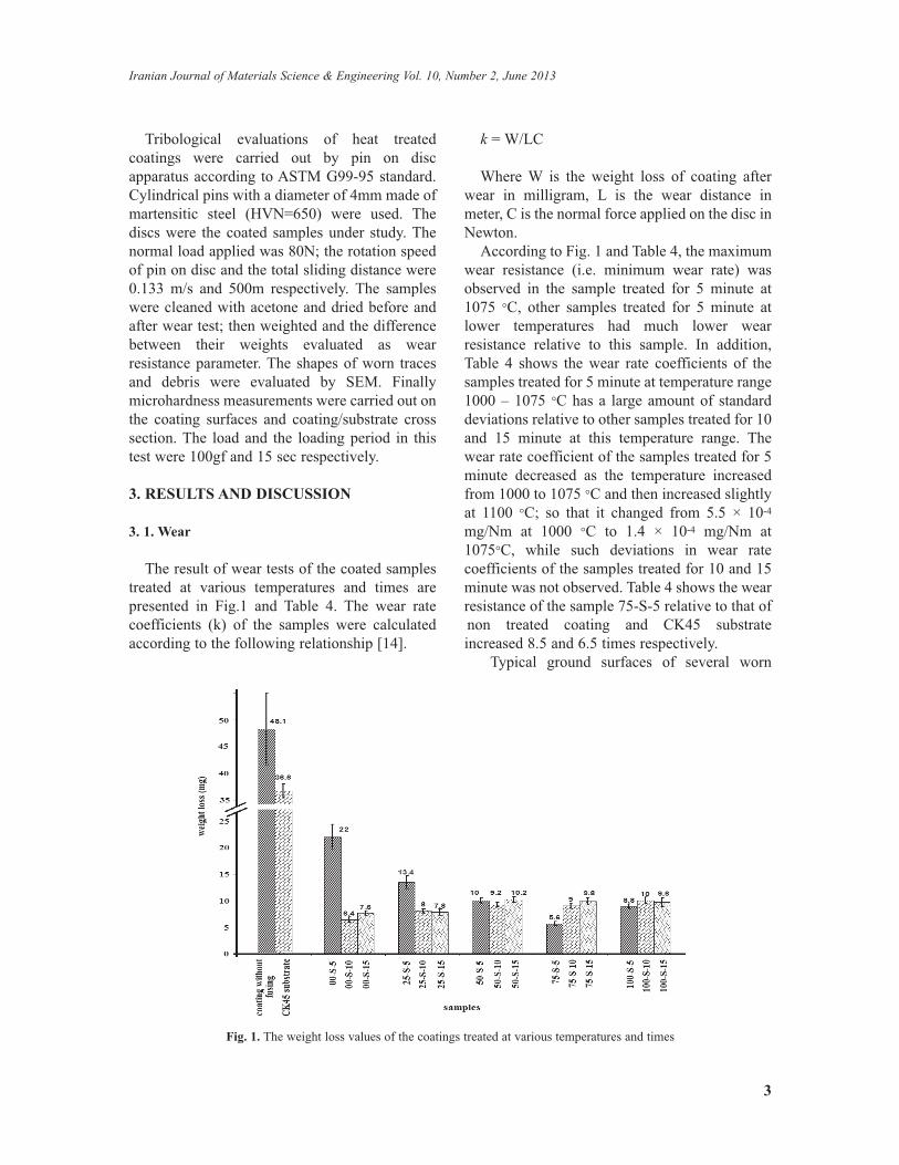
The result of wear tests of the coated samplestreated at various temperatures and times arepresented in Fig.1 and Table 4. The wear ratecoefficients (k) of the samples were calculatedaccording to the following relationship [14].
k = W/LCWhere W is the weight loss of coating after
wear in milligram, L is the wear distance inmeter, C is the normal force applied on the disc inNewton.
According to Fig. 1 and Table 4, the maximumwear resistance (i.e. minimum wear rate) wasobserved in the sample treated for 5 minute at1075 °C, other samples treated for 5 minute atlower temperatures had much lower wearresistance relative to this sample. In addition,Table 4 shows the wear rate coefficients of thesamples treated for 5 minute at temperature range1000 – 1075 °C has a large amount of standarddeviations relative to other samples treated for 10and 15 minute at this temperature range. Thewear rate coefficient of the samples treated for 5minute decreased as the temperature increasedfrom 1000 to 1075 °C and then increased slightlyat 1100 °C; so that it changed from 5.5 × 10⁻⁴mg/Nm at 1000 °C to 1.4 × 10⁻⁴ mg/Nm at1075°C, while such deviations in wear ratecoefficients of the samples treated for 10 and 15minute was not observed. Table 4 shows the wearresistance of the sample 75-S-5 relative to that ofnon treated coating and CK45 substrateincreased 8.5 and 6.5 times respectively.
Typical ground surfaces of several worn
Fig. 1. The weight loss values of the coatings treated at various temperatures and times

4
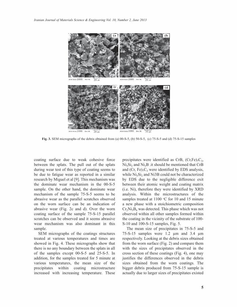
samples are presented in Fig. 2 and theircorresponding debris of these worn surfaces inFig. 3. Fig. 3 shows the debris obtained from thesample 00-S-5 are large and have plateletmorphology, while those obtained from sample50-S-5 are smaller and have both polygonal andplatelet shapes. The debris obtained from 75-S-5and 75-S-15 samples were polygonal, however themean size of 75-S-5 sample's debris was smallerthan that obtained from 75-S-15 sample. In
addition, some of the worn areas on sample 00-S-5contain very wide and deep grooves and it seemsthat they were formed due to pull out of thecoating splats from the coated surface, while thegroves observed in 75-S-5 and 75-S-15 samplesare mainly parallel scratches rather than pull outof splats.
Considering the topography of the wornsurface of 00-S-5 sample (Fig. 2a and b), one canobserve the splats were pulled out from the
H. Arabi, S. Rastegari, V. Ramezani and Z. Valefi
Heat treatment cycle
°C, min, AC*
Sample Code Heat treatment cycle
°C, min, AC*
Sample
Code
1000, 5, AC 00-S-5 1050, 15, AC 50-S-15
1000, 10, AC 00-S-10 1075, 5, AC 75-S-5
1000, 15, AC 00-S-15 1075, 10, AC 75-S-10
. 1025, 5, AC 25-S-5 1075, 15, AC 75-S-15
1025, 10, AC 25-S-10 1100, 5, AC 100-S-5
1025, 15, AC 25-S-15 1100, 10, AC 100-S-10
1050, 5, AC 50-S-5 1100, 15, AC 100-S-15
1050, 10, AC 50-S-10
* Air Cooled
Table 4. The average values of wear rate coefficient (WRC) of coatings treated at various temperatures and times
Fig. 2. SEM micrographs of worn surfaces of (a) and (b) 00-S-5, (c) and (d) 75-S-5, (e) and (f) 75-S-15 samples
5
Iranian Journal of Materials Science & Engineering Vol. 10, Number 2, June 2013
coating surface due to weak cohesive forcebetween the splats. The pull out of the splatsduring wear test of this type of coating seems tobe due to fatigue wear as reported in a similarresearch by Miguel et al [9]. This mechanism wasthe dominate wear mechanism in the 00-S-5sample. On the other hand, the dominate wearmechanism of the sample 75-S-5 seems to beabrasive wear as the parallel scratches observedon the worn surface can be an indication ofabrasive wear (Fig. 2c and d). Over the worncoating surface of the sample 75-S-15 parallelscratches can be observed and it seems abrasivewear mechanism was also dominant in thissample.
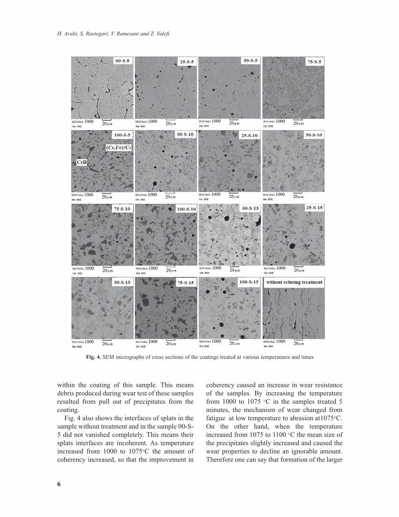
SEM micrographs of the coatings structurestreated at various temperatures and times areshowed in Fig. 4. These micrographs show thatthere is no any boundary between the splats in allof the samples except 00-S-5 and 25-S-5. Inaddition, for the samples treated for 5 minute atvarious temperatures, the mean size of theprecipitates within coating microstructureincreased with increasing temperature. These
precipitates were identified as CrB, (Cr,Fe)7C3,Ni5Si2 and Ni3B .it should be mentioned that CrBand (Cr, Fe)7C3 were identified by EDS analysis,while Ni5Si2 and Ni3B could not be characterizedby EDS due to the negligible difference exitbetween their atomic weight and coating matrix(i.e. Ni), therefore they were identified by XRDanalysis. Within the microstructures of thesamples treated at 1100 °C for 10 and 15 minutea new phase with a stoichiometric compositionCr2Ni3B6 was detected. This phase which was notobserved within all other samples formed withinthe coating in the vicinity of the substrate of 100-S-10 and 100-S-15 samples, Fig. 5.
The mean size of precipitates in 75-S-5 and75-S-15 samples were 1.2 µm and 3.4 µmrespectively. Looking at the debris sizes obtainedfrom the worn surface (Fig. 2) and compare themwith the sizes of precipitates observed in thecross section of these coatings (Fig. 4), one mayjustifies the differences observed in the debrissizes obtained from the worn coatings. Thebigger debris produced from 75-S-15 sample isactually due to larger sizes of precipitates existed
Fig. 3. SEM micrographs of the debris obtained from (a) 00-S-5, (b) 50-S-5, (c) 75-S-5 and (d) 75-S-15 samples
6
within the coating of this sample. This meansdebris produced during wear test of these samplesresulted from pull out of precipitates from thecoating.
Fig. 4 also shows the interfaces of splats in thesample without treatment and in the sample 00-S-5 did not vanished completely. This means theirsplats interfaces are incoherent. As temperatureincreased from 1000 to 1075°C the amount ofcoherency increased, so that the improvement in
coherency caused an increase in wear resistanceof the samples. By increasing the temperaturefrom 1000 to 1075 °C in the samples treated 5minutes, the mechanism of wear changed fromfatigue at low temperature to abrasion at1075°C.On the other hand, when the temperatureincreased from 1075 to 1100 °C the mean size ofthe precipitates slightly increased and caused thewear properties to decline an ignorable amount.Therefore one can say that formation of the larger
H. Arabi, S. Rastegari, V. Ramezani and Z. Valefi
Fig. 4. SEM micrographs of cross sections of the coatings treated at various temperatures and times

precipitates larger precipitates within the coatingmicrostructure (Fig. 4) was one of the maincauses of reduction in wear resistance. Forimproving the resistance of wear one should notonly increases the coherency between the splatsbut also reduces the mean size of the coatingconstituent particles as much as possible. Thehigher resistance of wear in sample 75-S-5 isbasically related to the better coherency betweencoating splats and smaller precipitates distributedmore homogenously within the coatingmicrostructure of this sample.
For a single temperature when the time of heattreatment increased from 5 minutes to 10 and 15minutes did not cause noticeable effect on wearresistance, however when the temperatureincreased at a constant treatment time (10 and 15minutes), the rates of wear slightly increased.
Fig. 4 also indicates that the mean sizes ofprecipitates in all of the samples treated for either10 or 15 minutes are larger than those treated for5 minutes and the wear rates of the formersamples are higher than those of the later ones. Inaddition, it can be seen in Fig. 4 that themicrostructures of samples 00-S-10 and 00-S-15are similar to microstructure of sample 75-S-5,their wear rates are approximately similar, andhowever the wear resistance of 75-S-5 is betterthan the other two samples. Higher magnificationof the coating microstructures of some of thesamples in Fig.4 can be seen in Fig.5.3. 2. Microhardness
Variation of microhardness in coating /substrate cross section for various coated samples
7
Iranian Journal of Materials Science & Engineering Vol. 10, Number 2, June 2013
Fig. 5. SEM micrographs of cross section of (a) 75-S-15, (b) 100-S-10, (c) 100-S-15 and (d) 100-S-10 at highermagnification than Fig.4
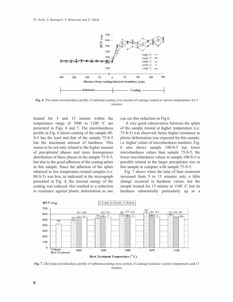
treated for 5 and 15 minute within thetemperature range of 1000 to 1100 °C arepresented in Figs. 6 and 7. The microhardnessprofile in Fig. 6 shows coating of the sample 00-S-5 has the least and that of the sample 75-S-5has the maximum amount of hardness. Thisseems to be not only related to the higher amountof precipitated phases and more homogenousdistribution of these phases in the sample 75-S-5,but also to the good adhesion of the coating splatsin this sample. Since the adhesion of the splatsobtained in low temperature treated samples (i.e.00-S-5) was low, as indicated in the micrographpresented in Fig. 4, the internal energy of thecoating was reduced; this resulted to a reductionin resistance against plastic deformation as one
can see this reduction in Fig.6.A very good cohesiveness between the splats
of the sample treated at higher temperature (i.e.75-S-5) was observed; hence higher resistance toplastic deformation was expected for this sample,i.e. higher values of microhardness numbers. Fig.6 also shows sample 100-S-5 has lowermicrohardness values than sample 75-S-5, thelower microhardness values in sample 100-S-5 ispossible related to the larger precipitates size inthis sample in compare with sample 75-S-5.
Fig. 7 shows when the time of heat treatmentincreased from 5 to 15 minutes only a littlechange occurred in hardness values, but thesample treated for 15 minute at 1100 °C lost itshardness substantially particularly up to a
8
H. Arabi, S. Rastegari, V. Ramezani and Z. Valefi
Fig. 6. The mean microhardness profile of substrate/coating cross section of coatings treated at various temperatures for 5minutes
Fig. 7. The mean microhardness profile of substrate/coating cross section of coatings treated at various temperatures and 15minutes
distance of 150 µm from its interface from thesubstrate. This observation might be related tothe formation of Cr2Ni3B6 precipitates in 100-S-15 sample that was mentioned in previoussections. The coating microstructure of thissample can be seen in Fig. 5.
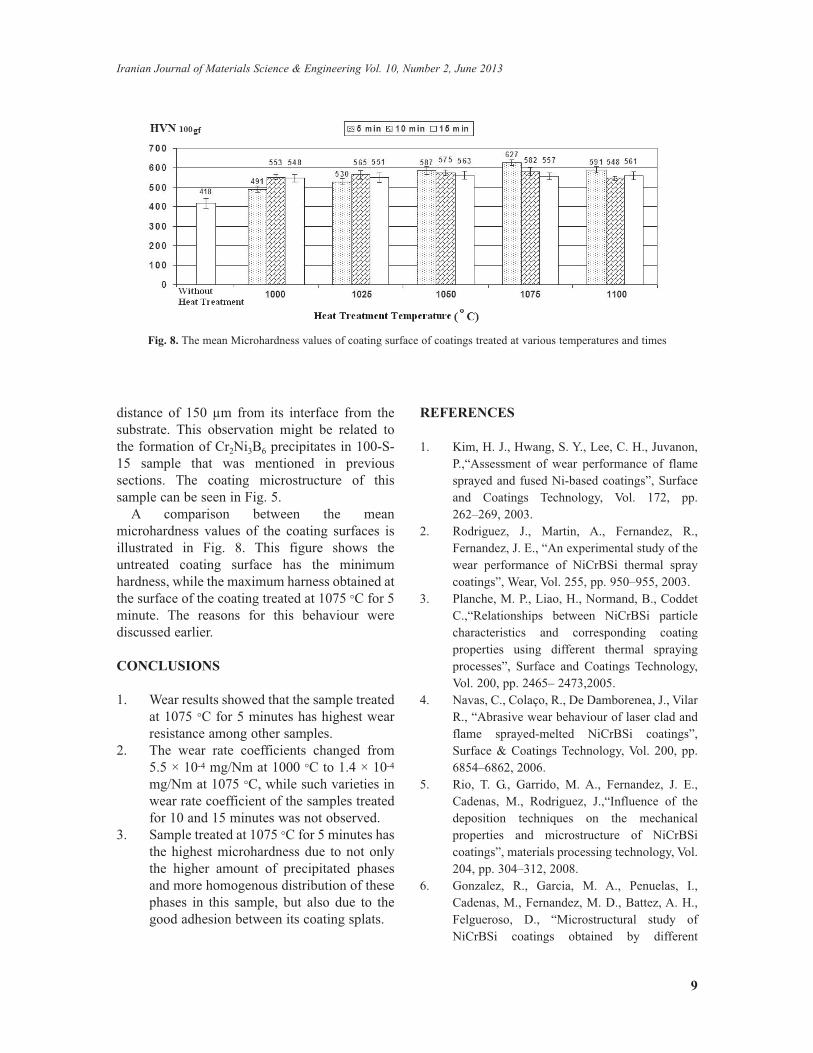
A comparison between the meanmicrohardness values of the coating surfaces isillustrated in Fig. 8. This figure shows theuntreated coating surface has the minimumhardness, while the maximum harness obtained atthe surface of the coating treated at 1075 °C for 5minute. The reasons for this behaviour werediscussed earlier.CONCLUSIONS
1. Wear results showed that the sample treatedat 1075 °C for 5 minutes has highest wearresistance among other samples.
2. The wear rate coefficients changed from5.5 × 10-4 mg/Nm at 1000 °C to 1.4 × 10⁻⁴mg/Nm at 1075 °C, while such varieties inwear rate coefficient of the samples treatedfor 10 and 15 minutes was not observed.
3. Sample treated at 1075 °C for 5 minutes hasthe highest microhardness due to not onlythe higher amount of precipitated phasesand more homogenous distribution of thesephases in this sample, but also due to thegood adhesion between its coating splats.
REFERENCES
1. Kim, H. J., Hwang, S. Y., Lee, C. H., Juvanon,P.,“Assessment of wear performance of flamesprayed and fused Ni-based coatings”, Surfaceand Coatings Technology, Vol. 172, pp.262–269, 2003.
2. Rodriguez, J., Martin, A., Fernandez, R.,Fernandez, J. E., “An experimental study of thewear performance of NiCrBSi thermal spraycoatings”, Wear, Vol. 255, pp. 950–955, 2003.
3. Planche, M. P., Liao, H., Normand, B., CoddetC.,“Relationships between NiCrBSi particlecharacteristics and corresponding coatingproperties using different thermal sprayingprocesses”, Surface and Coatings Technology,Vol. 200, pp. 2465– 2473,2005.
4. Navas, C., Colaço, R., De Damborenea, J., VilarR., “Abrasive wear behaviour of laser clad andflame sprayed-melted NiCrBSi coatings”,Surface & Coatings Technology, Vol. 200, pp.6854–6862, 2006.
5. Rio, T. G., Garrido, M. A., Fernandez, J. E.,Cadenas, M., Rodriguez, J.,“Influence of thedeposition techniques on the mechanicalproperties and microstructure of NiCrBSicoatings”, materials processing technology, Vol.204, pp. 304–312, 2008.
6. Gonzalez, R., Garcia, M. A., Penuelas, I.,Cadenas, M., Fernandez, M. D., Battez, A. H.,Felgueroso, D., “Microstructural study ofNiCrBSi coatings obtained by different
9
Iranian Journal of Materials Science & Engineering Vol. 10, Number 2, June 2013
Fig. 8. The mean Microhardness values of coating surface of coatings treated at various temperatures and times
processes”, Wear, Vol. 263, pp. 619–624, 2007.7. Ming, Q., Lim, L. C., Chen, Z. D., “Laser
cladding of nickel-based hardfacing alloys”,Surface and Coatings Technology, Vol. 106, pp.174–182, 1998.
8. Fernandez, E., Cadenas, M., Gonzalez, R.,Navas, C., Fernandez, R., Damborenea J. D.,“Wear behaviour of laser clad NiCrBSicoating”, Wear, Vol. 259, pp. 870–875, 2005.
9. Miguel, J. M., Guilemany, J. M., Vizcaino, S.,“Tribological study of NiCrBSi coatingobtained by different processes”, TribologyInternational, Vol. 36, pp. 181–187, 2003.
10. Tobar, M. J., Álvarez, C., Amado, J. M.,Rodríguez, G., Yáñez, A.,“Morphology andcharacterization of laser clad compositeNiCrBSi–WC coatings on stainless steel”,Surface & Coatings Technology, Vol. 200, pp.6313–6317, 2006.
11. Gonzalez, R., Cadenas, M., Fernandez, R.,Cortizo, J. L., Rodriguez, E., “Wear behaviourof flame sprayed NiCrBSi coating remelted byflame or by laser”, Wear, Vol. 262, pp. 301–307,2007.
12. Liang, G. Y., Wong, T. T., MacAlpine, J. M. K.,Su; J. Y., “A study of wear resistance of plasma-sprayed and laser-remelted coatings onaluminium alloy”, Surface and CoatingsTechnology, Vol. 127, pp.233–238, 2000.
13. Yang, Q., Senda, T., Ohmori, A.,“Effect ofcarbide grain size on microstructure and slidingwear behavior of HVOF-sprayed WC – 12%Co coatings”, Wear, Vol. 254, pp. 23–34, 2003.
14. WEAR – Materials Mechanisms and Practice -Edited by: Gwidon W. Stachowiak, 2006, Ch.2,Published by: John Wiley & Sons Ltd, TheAtrium, Southern Gate, Chichester,West SussexPO19 8SQ, England
10
H. Arabi, S. Rastegari, V. Ramezani and Z. Valefi