influence of film thickness on the performance of solid
TRANSCRIPT

Scholars' Mine Scholars' Mine
Masters Theses Student Theses and Dissertations
1970
Influence of film thickness on the performance of solid lubricants Influence of film thickness on the performance of solid lubricants
Sunil Vishwanath Mahale
Follow this and additional works at: https://scholarsmine.mst.edu/masters_theses
Part of the Mechanical Engineering Commons
Department: Department:
Recommended Citation Recommended Citation Mahale, Sunil Vishwanath, "Influence of film thickness on the performance of solid lubricants" (1970). Masters Theses. 7163. https://scholarsmine.mst.edu/masters_theses/7163
This thesis is brought to you by Scholars' Mine, a service of the Missouri S&T Library and Learning Resources. This work is protected by U. S. Copyright Law. Unauthorized use including reproduction for redistribution requires the permission of the copyright holder. For more information, please contact [email protected].

INFLUENCE OF FILM THICKNESS ON THE PERFORMANCE
OF SO LID LUBRICANTS
BY
SUNIL VISHWANATH MAHALE, 1945 -
A
THESIS
submitted to the faculty of
THE UNIVERSITY OF MISSOURI-ROLLA
ln partial fulfillment of the requirements for the
Degree of
MASTER OF SCIENCE IN MECHANICAL ENGINEERING
Rolla, Missouri
1970
Approved by
4L«~cLJC:visor) /?{&iv-~ ~ (~ }- );-A-%-
ClU >

Abstract
The object of this investigation was to determine the
effect of lubricant film thickness on the coefficient of
friction and on the wear life of solid lubricants. Bonded
molybdenum disulphide and bonded graphite were the lubri-
cants tested. Dow Corning's LFW-1 and Falex lubricant
tester were the two machines used for testing these lubri
cants.
The lubricants were sprayed on the specimen surface.
ll
Pretreatment, spraying and curlng were done according to
standard or manufacturer's recommended procedures. During
the entire research, the procedure for experimentation was
followed according to ASTM No. 2625 on Falex and CRC recom
mendations on LFW-1 machine.
It was found that the film thickness lS an important
factor in deciding performance of a solid lubricant. The
coefficient of friction increases with increase in film
thickness for thicknesses in the range tested (0.0017 in.
to 0.0007 in.). For a maximum wear life, there is a definite
optimum film thickness, above and below which the wear life
decreases.

lll
ACKNOWLEDGEMENT
The author wishes to express his Slncere appreciation
to Professor Schowalter and Dr. Harry J. Sauer for their
advice throughout the investigation.
The writer is also indebted to Professor R. V. Wolf
for his advice regarding measurement of film thickness.
The author is thankful to Mr. Bart J. Banjac of
Dynacraft Inc. of St. Louis, Missouri for providing lubri
cating material and phosphating chemicals free of charge.
The help of Dick Smith is sincerely appreciated.
Thanks goes to Judy Guffey for typing the manuscript.
The author would also like to thank his parents for
their encouragement and support.

Abstract .
ACKNOWLEDGEMENT
LIST OF FIGURES
LIST OF TABLES
NOMENCLATURE .
I. INTRODUCTION .
TABLE OF CONTENTS
II. REVIEW OF LITERATURE ..
lV
Page
ll
lll
Vl
lX
X
1
5
III. DESCRIPTION OF EXPERIMENTAL EQUIPMENT . . . 9
A. Dow Corning's LFW-1 Variable Drive Machine 9
B. Falex Lubricant Tester . 13
C. Magne Gauge 19
IV. EXPERIMENTAL METHOD 21
A. Preparation of Specimen and Application of
Lubricant 21
1. Degreasing 21
2. Phosphating 21
3. Application of Coating and Measurement
of Thickness
B. Test Procedure .
1. LFW-1 Machine
2. Falex Lubricant Tester
V. RESULTS ...
A. Electrofilm Lubricant - LFW-1 Machine
22
22
22
24
25
25

B. Graphite Lubricant - LFW-1 Machine .
C. E1ectrofi1m Lubricant - Fa1ex Tester
VI. CONCLUSION .
VII. BIBLIOGRAPHY .
VIII. VITA .
v
Page
36
41
47
48
49

vi
LIST OF FIGURES
Figure Page
l. Film Thickness Versus Wear Rate for Bonded PbO
Lubricant 6
2. Film Thickness Versus Coefficient of Friction for
Bonded PbO Lubricant 6
3. Wear Life Versus Coefficient of Friction for
Inorganically Bonded Lubricant 7
4. Experimental Set-Up on LFW-1 Machine 10
5. Close-Up View of Ring and Block Assembly on LFW-1
6 .
7 .
8 .
9 .
10.
11.
Machine .
Schematic Drawing Showing Operational Principle
on LFW-1 Machine
Photograph of Ring and Block
Dimensional Drawing of Test Ring
Dimensional Drawing of Test Block .
Experimental Set-Up on Falex Lubricant Tester
Exploded View of 'V' Blocks and Journal
12. Coefficient of Friction Calculations on Falex
Lubricant Tester
a. Assembly of Test Blocks and Journal
b. Free Body Diagram of Journal
c. Free Body Diagram of Test Block
13. Photograph of Journal and Blocks
14. Measurement of Film Thickness on Magne Gauge
10
ll
ll
14
14
15
15
17
17
17
17
18
20

Vll
Figure Page
15. Effect of Increase in Load on Frictional Force
for Electrofilm Lubricant .
16. Wear Life Versus Coefficient of Friction for
Electrofilm Lubricant .
17. Plot of Minimum Coefficient of Friction Versus
Film Thickness for Electrofilm Lubricant
18. Effect of Film Thickness on Wear Life for Elec
trofilm Lubricant .
19. Effect of Film Thickness on Wear Rate for Elec
trofilm Lubricant
2 0 .
21.
Bare Ring Surface after Degreasing at lOOX
Ring Surface after Coated with Solid Film Lubri
cant at lOOX
22. Ring Surface at Optimum Performance Taken at 100
27
28
29
30
31
33
33
Magnification . 34
23. Ring Surface at the End of Wear Test QOOX). 34
24. Microscopic Photograph of the Ring Surface from
Electron Microscope (lOOOX) 35
a.
b.
c .
d.
Bare Ring Surface after Degreasing
Ring Surface after Coated with Solid Film
Lubricant .
Ring Surface at Optimum Performance
Photograph of the Surface at the End of Wear
Test
35
35
35
35

Vlll
Figure Page
25. Effect of Increase in Load on Frictional Force
for Graphite Lubricant .
26. Wear Life Versus Coefficient of Friction for
Graphite Lubricant .
27. Effect of Film Thickness on Wear Life for
Graphite Lubricant .
28. Plot of Minimum Coefficient of Friction Versus
Film Thickness for Graphite Lubricant
29. Effect of Film Thickness on Wear Rate for
Graphite Lubricant .
30. Effect of Film Thickness on Wear Life of Elec
trofilm Lubricant
31. Effect of Film Thickness on Wear Rate for Elec
trofilm Lubricant
38
39
40
42
43
45
46

lX
LIST OF TABLES
Table Page
I. Data for Electrofilm Lubricant on LFW-1
II.
III.
Machine .
Data for Graphite Lubricant on LFW-1 Machine
Data for Electrofilm Lubricant on Falex
Machine .
26
37
44

NOMENCLATURE
Symbol Significance
D.L. Direct Load
N Normal Reaction
f Frictional Force
P,Q Constraint Force
T Torque
)J Coefficient of Friction
w Normal Load on Specimen
E Young's Modulus of Elasticity
L Width of Cylinder
D Outer Diameter of Ring
Units
Lb.
Lb.
Lb.
Lb.
Lb.-In.
Lb.
Lb. 2 In.
In.
In.
X

l
I. INTRODUCTION
Between one third and one half of all energy produced
ln the world is presently lost in friction; however, we can
expect this figure to shrink in the face of continued
research on solid and other lubricants. Even a minor de-
crease in friction between moving parts can on a world wide
basis, bring about a dramatic reduction in total energy
lost due to friction. Since the mid 1930's a strong trend
has developed toward using higher and higher temperatures
ln moving parts. The space program has moved the operation
of many systems to the void of outer space. One result of
these trends has been the development and use of solid lubri
cants to attain the necessary lubrication of parts at extreme
temperatures and vacuum.
A solid lubricant can generally be defined as a material
that provides lubrication between two moving surfaces under
dry conditions. W. E. Campbell(l) gives a physical explana-
tion of the mechanism of solid friction. He states that
when two surfaces are brought in contact under moderate pres-
sure, the real area of contact is only a small fraction of
the total interface area. Pressure welding of two surfaces
takes place because of high pressure on the small area of
contact and, when relative motion takes place, the friction
force is predominently that necessary to shear these welded
joints. This friction force is tremendously reduced by using

2
a solid lubricant between the sliding surfaces. Alfred( 2 )
has given a scientific explanation for the performance of
bonded solids as lubricating materials. Many inorganic
solids, such as graphite, are slippery when finely divided.
In powdered form, these materials can fill in pores and
valleys of mating surfaces providing on-the-spot lubrication
for the peaks and ridges that tend to weld together at high
loads and low velocities.
To date, solid lubricants are considered for use only
where conventional liquid lubricants can not be used, since
liquid lubricants normally result in a lower coefficient of
friction. In the immediate future, the solid lubricants
will not displace the more conventional lubricants but,
rather, they will open up new frontiers to operating machin-
ery. The proper application of solid lubricants will permit
the successful operation of machinery under conditions of
very high temperature, very high vacuum, nuclear radiation,
extreme loads and chemically reactive environments.
Alfred( 2 ) discusses the importance of the layered
lattice structure of solid lubricants and he emphasizes that
it is the major key to the behavior of this type of inor-
ganlc solid lubricants. Molecular bonds within each layer
are strong, whereas layer to layer bonds are weak. Thus
surface asperities have difficulty in penetrating layers,
but slide easily over one another because layer-to-layer
bonds of the lubricant are readily sheared. In fact, shearing

takes place when loads are high, exactly reverse of hydro-
dynamic lubrication. This unusual characteristic makes
solid films well suited to extreme pressure lubrication.
Molybdenum disulphide is a layered lattice material. In
this compound, the sulphur layers slide easily on one
another. But within the individual layers cohesive forces
between Mo & S atoms are very strong and hence resist pene-
tration by surface asperities. MoS 2 adheres well to metal
surface because the exposed sulphur atoms have strong
affinity for metals. Service life of bonded lubricants
depends greatly on the bond established between binder and
base metal. Three precoating factors improve this bond;
cleaning, mechanical roughening and chemical conversion of
surface. In addition to providing micro-roughness to the
mechanically roughened surface, chemical treatment gives a
cushioning layer that further impedes clean metal 'welding'
as surface asperities interfere.
M. E. Campbell( 3 ) defines bonded solid lubricants as
a series of lubricating materials consisting of friction
and wear reducing solids or pigments, such as MoS 2 or
graphite, attached to the bearing surface with a adhesive
material. The adhesive material may be organic in nature
(phenolic, epoxy, polymide resins) or inorganic (sodium
silicate, aluminum phosphate, fused ceramic).
NASA b . . D" . . ( 4 ) h Technology Pu llcatlon lVlSlon as published
3
information about different types of bonded lubricants. The

4
organically bonded materials can be used successfully ln high
load, low speed sliding applications and for moderate speed
at loads in antifriction bearing application. Their useful
temperature lS somewhat limited from approximately -l00°F
to +400°F. At higher temperature the lubricating solids
tend to oxidize and the resin binder rapidly degrades by
heat causing film failure from lack of film adhesion. For
improved temperature performance, high temperature polymides
are used as the binder solution. The solid lubricants with
these binders are very heat stable and exhibit useful life
at temperatures to l000°F in air and to above l300°F in an
inert atmosphere.
M. E. ( 3 ) Campbell also states that inorganically bonded
lubricants can be divided into two subgroups, ceramic and
nonceramically bonded. Phosphates and silicates are used
as binding material for non-ceramic solid lubricants. Prin-
cipal advantages of these types of lubricants are; (l) they
are not subjected to outgassing in a vacuum of 10- 9 torr and
(2) they are compatible with oxygen. Therefore, they are
very useful in the space program. However, they do not
afford corrosion protection and the film softens when sub-
jected to water or moisture for extended periods of time.
The object of this research was to determine the effect
of film thickness on wear life and on the coefficient of
friction for solid film lubricants. An attempt is also made
to find the relation between the rate of wear and the film
thickness.

5
II. REVIEW OF LITERATURE
There are many references on var1ous aspects of solid
lubrication. The majority of these are listed in references
C 5) and ( 6). Only those specifically related to this work
are discussed here.
J h . (7)
o nson and Sl1ney present the results of an exper1-
mental study on the effect of film thickness on coefficient
of friction and wear rate. Lead oxide was used as the solid
lubricant and testing was done on a rider-disc type of tester.
Tests were conducted at l200°F with a load of l Kg. on
Ni-Cr-Fe alloy rider at a disc speed of 435 fpm. To achieve
good repeatability, the disc was ground flat and parallel
to within 0.0005 of an inch and then coated accurately with
lead oxide after necessary pretreatments. Figure l and 2
illustrate the effect of coating thickness on the coeffi-
cient of friction and on rider wear. From the graphs it
appears that the wear rate continues to increase with film
thickness, without limit. The coefficient of friction in-
creases linearly with film thickness.
Alfred( 2 ) states that line contact and area contact
methods closely simulate conditions in actual mechanisms.
The results of his tests on electrophoratically coated,
inorganically bonded MoS 2 lubricant are shown in Fig. 3.
Friction coefficient decreases as normal load increases.

. "\
L{)
0
12 ><
(Y)IZ z- 8 -~ .e':"-~-
LLJ 4 1-<(
CL:
0::: <(
0 0 2 4 6
6
8 LLJ 3: FILM THICKNESS IN.X 10 4
z: 0
1-C)
C:~~
l.L.
LL 0
LL lL w 0 0
Fig. l Film Thickness Versus Wear Rate for Bonded PbO Lubricant
. 4
. 3
. 2
• I
0 0 2 4 6 8 FILM THICKNESS - IN.X
Fig. 2 Film Thickness Versus Coefficient
104
of Friction for Bonded PbO Lubricant

f6 (\J
0 ->< z f 2 0 -J-(.)
-o:: 8 LL.
lL 0
lJ_ 4 lJ_
LU 0 0
0 10 roo I , 000 10,000
,~,'A R iV C. I LIFE - CYCLES
Fig. 3 Wear Life Versus Coefficient of Friction for Inorganically Bonded Lubricant
60,000
---.)

The flat portion of the curve gives the mlnlmum coefficient
of friction for the coating while the sudden upturn of the
curve gives wear life.
8

III. DESCRIPTION OF EXPERIMENTAL EQUIPMENT
A. Dow Corning's LFW-1 Variable Drive Machine
The LFW-1 lS a versatile and accurate screening device
for evaluation of lubricants and bearing materials in unl
directional motion. It has also been found adaptable for
testing under low load, area contact, and oscillating con
ditions. A photograph of the experimental set up on this
machine is shown on Fig. 4. A close up photograph of the
rlng and block in running condition is shown in Fig. 5.
Schematic representation of actual operation is shown
ln Fig. 6. Figure 7 is a photograph of two sets of speci
mens, one unused and the other after testing.
A stationary block is pressed against a predetermined
load (maximum 630 lbs.) against a rotating disc. Average
Hertz pressure in the line contact area between rectangular
specimen and the rotating rlng may range up to 11,000 psi.
The resulting friction is indicated throughout the test by
a dial indicator. A counter records the number of revolu-
tions of the test speclmen. A control pointer on the fric-
tion indicator can be set for any preselected value of
friction and the machine will automatically shut off upon
reaching it.
The test shaft of the machine is supported by two
roller bearings and the mandrel end of the shaft protrudes
through the front panel o£ the machine where the speclmens
9

Fig. 4 Experimental Set-Up on LFW-1 Machine
Fig. 5 Close-Up View of Ring and Block Assembly on LFW- 1 Machine
10

I friction load pick-up
11
.a;t;;.~--maximum load 630 lbs .
~---~• test block cylindincally seated for uniform load distribution over entire line contact area
friction force at line of contact directly transmitted to load pick-up
Fig. 6 Schematic Drawing Showing Operational Principle on LFW-1 Machine
Fig. 7 Photograph of Ring and Block

12
are mounted. The test block, which is held stationary
against the revolving ring, is restrained from horizontal
movement by a unique type of holder. The design of this
block holder allows the test block to align itself automa
tically in a manner prescribed by ASTM specifications for
compression loaded specimens. This maintains uniform load
ing throughout the area of contact between the speclmens
regardless of the force existing between them.
The normal force between the test specimens lS pro
duced by hanging dead weights on the lower end of a com
pound lever system which is designed in such a way as to
allow the full value of the friction force to be transmitted
to the frictional load pick up device. The compound lever
produces leverage of 1:30, due to which a vertical load of
1 lb. produces a normal load of 30 lbs. on the speclmens.
The friction force indicator reads directly in pounds and
is fitted with an infinitely adjustable limit control which
allows the operator to preset the value of friction at which
the machine will stop. This setting is accomplished with
out the use of tools by a knurled knob located in the center
of the dial face outside of the glass.
A SlX digit revolution counter lS panel mounted in the
top of the case. It is driven from the test shaft and is
equipped with reset wheel which can be controlled from out
side of the case.

Figure 8 is a dimensional drawing of the test rlng.
The rlng lS made up of SAE 4620 steel having a Rockwell
hardness of HRc 58 to 63. It has a ground face of 0.321
± 0.0005 ln. wide and a diameter of 1.3775 + 0.0001
13
- 0.0005 ln. having eccentricity between the inner and outer
surface no greater than 0.0015 in. The surface finish
range of the outside diameter surface of the ring is from
5 to 15 micro-in. rms in the direction of motion.
The test block is shown in Fig. 9. It is made up of
SAE 01 cold worked 0.250 + 0.0005 - 0.000 in. wide and
0.620 ± 0.0005 in. long having a Rockwell hardness of HRc
30 ± 3. Each block lS supplied with the test surface ground
to a surface finish of 4 to 8 micro-in. rms, being perfectly
square with all outside edges.
B. Falex Lubricant Tester
A photograph of the experimental set-up lS shown in
Fig. 10. Exploded vlews of the V-blocks and the journal are
shown in Fig. ll. The bearing blocks can be inserted in
the short lever arms, or jaws, of the load applying mechanism
which fits loosely over bifurcated ends of long lever arms.
The ratchet wheel is turned by hand until the loading
mechanism takes hold, this is indicated by a registration
of applied load on the gauge. Additional load can be applied
either by turning up the ratchet wheel by hand, or by engag
ing the load applying arm with the ratchet wheel. The
eccentric motion of load applying arm increases the application

14
Fig. 8 Dimensional Drawing of Test Ring
t- 0. 6 201 I j_
I * I 0.250
Fig. 9 Dimensional Drawing of Test Block

15
Fig . 10 Experimental Set-Up on Falex Lubricant Tester
brass ~ocking~ ~ pln ~~
~ ~journal revolving ~ ~ at 290 rpm
~ ~~V' block
Fig. 11 Exploded View of ' V' Blocks and Journal

16
of load, one tooth at time. The action lS similar to the
action of a mechanically operated pair of pliers. The
entire mechanism is free to swing about its axis, this
tendency to turn being resisted by the syphon operated
gauge which registers torque. Instantaneous wear of spe
cimens can be measured from the ratchet wheel. The entire
ratchet wheel lS divided into 200 divisions, and every 18
teeth on ratchet equals 0.001 ln. of wear. Free body dia
grams of block and journal are shown in Fig. 12.
The standard test journal for the Falex lS 1/4 ln.
outside diameter by 1-l/4 in. long. It is made up of
AISI 3135 steel having a Rockwell Hardness B of 87 to 90
on a ground flat surface with a surface finish of 6 to
10 micro-in. rms. The assembly of journal and blocks lS
shown ln Fig. l2a and free body diagram of journal is
shown ln Fig. 12b.
The V-blocks are made from AISI C-1137 steel having
a Rockwell Hardness C of 20 to 24 with a surface finish
of 3 to 6 micro-in. rms. Free body diagram of a block
ls shown in Fig. 12c.
The locking pln lS 1/2 H brass, confirming to ASTM
specification B-16 for Free Cutting Brass Rod, Bar, and
Shapes for Use ln Screw Machines.
Figure 13 lS a photograph of two sets of speclmens
one unused and other after testing.

~ in. pln diameter blocks do
I not rotate
D. L -----~L.--1_ --~~~-TL.-~-t+-_ -_ ___,1· D. L
Fig. 12a Assembly of Test Blocks and Journal
f
N
f
Q
p
y
L--+-X
.._--D.L
17
Fig. 12b Free Body Diagram of Journal
Fig. 12c Free Body Diagram of Test Block
From Fig. b - L:M = 0 = 0
From Fig. c - L: F X = 0 =
f )J = N
T - 4 f ( !.) 8
D.L - 2Ncos42
0 2T(2cos42 ) = D.L
= 2.9724 _!__ D.L
f = 2T
0 N D.L
= 2cos42°
Fig. 12 Coefficient of Friction Calculations on Falex Lubricant Tester

18
Fig . 13 Photograph of Journal and Blocks

19
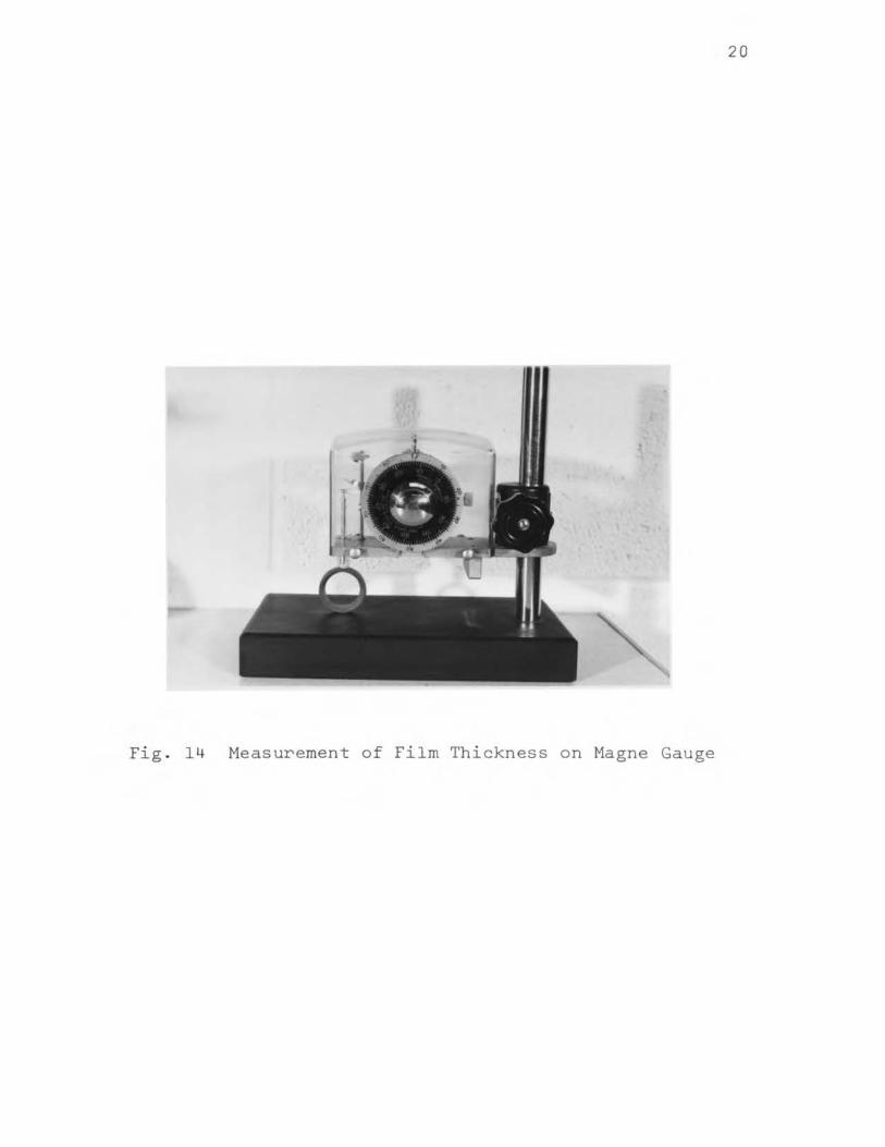
C. Magne Gauge
For measuring lubricant film thickness a Magne gauge
was used. A photographic view of this instrument is shown
in Fig. 14. Accuracy of this instrument is 0.0001 in. for
nonmagnetic film thickness on mild steel base. Measurements
are not appreciably affected by the thickness of the base
metal if it is over 0.01 in. thick.
The operating principal lS that the attractive force
between the magnet and speclmen is inversely proportional
to the film thickness. The force of attraction is balanced
by uncoiling a coiled spring. The degree of rotation re
quired is marked on a dial. Knowing the dial reading, film
thickness can be determined from calibration curves supplied
with the gauge.
20
Fig . 14 Measurement of Film Thickness on Magne Gauge

21
IV. EXPERIMENTAL METHOD
A. Preparation of Specimen and Application of Lubricant
1. Degreasing
Test specimens were degreased 1n trichloroethylene
bath. Then they were suspended in the vapor of boiling
benzene for 30 seconds and immersed in boiling methyl ethyl
ketone for 30 seconds. After air drying, specimens were
aga1n degreased 1n a trichlorethylene bath and finally
wiped with lint free cloth.
2. Phosphating
After decreasing, the speclmens were treated with Parco
Lubrite #5 solution. The process of treatment consist of
immersing the properly degreased work in the Parco Lubrite
solution at 180-185°F for approximately 10 minutes to form
a uniform protective coating. It is very important to
maintain the temperature in the range of 180-185°F. Boil-
1ng the solution will cause excessive use of Accelerator,
and not keeping it up to proper temperature will result in
a nonuniform coating.
Following the Parco Lubrite treatment, the work is
immersed in water for 30 to 60 seconds. A cold . .
r1nse lS
satisfactory, however, if the work is to be dried immediately,
a hot rinse is preferable to facilitate drying. It is desir-
able to rinse the work as soon as possible after process1ng,
as the Parco Lubrite solution tends to set up on hot metal

22
making it difficult to rlnse. The speclmens were oven dried
immediately after water rinse. The temperature of the oven • • 0 was malntalned below 225 F. The thickness of the phosphate
coat was measured with the Magne gauge.
3. Application of Coating and Measurement of Thickness
The lubricants, namely Electrofilm Lubri Bond 'A'
(molybdenum disulphide base) and LaFrance Franlube (graphite
base) available in aerosol cans, were sprayed on the surface
of the specimens. To achieve uniform coating, the speci-
mens were rotated at approximately 360 rpm. The film was
air cured for 8 hours and the specimens were kept in a dis-
sicator for the next 16 hours to eliminate detrimental
effects of humidity on the wear life.
The total thickness of phosphate and lubricant coat on
the surface of specimen was measured at several points. An
average of all these readings was considered as the final
thickness.
After complete treatment and measurement of coating
thickness, the rlng and block of LFW-1 machine were weighed
to the nearest 0.1 mg. on an analytical balance. Weighing
of the speclmens was done again after evaluation on the
testing machine.
B. Test Procedure
l. LFW-1 Machine
Before each test, the speclmen holder, the tapered sec-
tion, threaded section, lock nut and washer of the machine

23
were cleaned ln benzene and rinsed in methyl ethyl ketone.
The threaded portion and brass bushing was lubricated with
molykote lubricant. The test ring was mounted on the shaft.
The test ring on the shaft was locked with 250 ln. lb. of
wrench torque. After inserting the specimen block in the
quarter segment, the holder was inserted in the seat without
marrlng the surface of the ring. The clearance between
lower lever and lower safety bolt was kept between l/16 to
l/8 of an inch which insures that the lower lever will be
horizontal when the bale rod lS fully loaded.
The fixed reference of the lever system was aligned
before loading the specimen. When the markers were aligned,
the friction pin was backed off to reset the dial gauge to
zero. This insured that there was no preload on the fric-
tion measuring system.
The specimens were initially loaded with 60 lbs. The
speed was gradually increased to 72 rpm. The load was then
increased so that full load of 630 lbs was applied at the
end of 10 minutes. The weights were put on gradually to pre
vent shock loading. After every load change, the index and
fixed reference was readjusted. The speed was rechecked
after every load change and adjusted to 72 rpm. The number
of revolutions were recorded from the counter. Frictional
force was also recorded after each interval of 50 cycles.
The test was allowed to continue until the coefficient of
friction reached 0.1.
the nearest 0.1 mg.
The tested specimens were weighed to

24
The loading conditions were changed while testing
graphite lubricant, as the quality was not good compared to
Electrofilm lubricant. Load was 30 lbs. initially, and it
was increased to 240 lbs. in 8 minutes. Automatic shut off
was adjusted for a coefficient of friction equal to 0.2.
2. Falex Lubricant Tester
Before each test, the journal holder and the recess in
the loading device were cleaned with benzene and rinsed ln
methyl ethyl ketone. Solid film coated 'V' blocks were
inserted in the recess of the loading device. The solid
film coated test pin was inserted in the mandrel and was
held in position by a brass shear pln.
After positioning the loading device, the ratchet wheel
was turned by hand until the loading mechanism engages (in
dicated on load gauge). The load applying arm was posi
tioned and drive motor was energied until gauge load of 250
lbs. was reached. The test was continued at the constant
load of 250 lbs. The number of teeth required to maintain
this load was recorded as instantaneous wear. Average wear
rate was determined by dividing the total teeth wear by
wear life. The wear life or failure was indicated by a torque
rlse of 10 in. lb. above steady state value.

25
V. RESULTS
A. Electrofilm Lubricant - LFW-1 Machine
Condensed data of all tests is tabulated ln Table I.
The maximum Hertz pressure developed between block and rlng
(line contact) was 10,900 psi. The minimum coefficient of
friction is the lowest value obtained during the entire wear
life of operation and it is horizontal part of wear life
versus coefficient curve. Figure 15 shows the effect of an
increase in load on the frictional force. It can be seen
that for increasing thickness, the effect is negligible at
lower loads, but becomes considerable at higher loads.
Effect of film thickness on wear life can be studied from
Fig. 16. The range of coefficient of friction after 10
minutes was 0.0295 to 0.175, but at optimum condition it
was 0.03 to 0.07. The drop in coefficient of friction for
thicker coatings is considerable. A plot of minimum coef
ficient of friction versus film thickness lS shown in
Fig. 17, from which it can be seen that coefficient of
friction increased linearly with increase in film thickness.
A curve of film thickness versus wear life is shown in Fig. 18.
The wear life was maximum at a film thickness of 0.00028 in.
At greater thicknesses the wear life dropped drastically.
Figure 19, graphically shows the relation between film thick
ness and wear rate. The wear rate increases linearly at
lower thicknesses but the relation becomes exponential at
higher thickness. Initial wear in thicker coatings is

26
Lubricant: Electrofilm Lubri Bond 'A'
Machine: LFW-1
Speed: 72 RPM
Max. Load: 630 Lbs. (After 10 Minutes)
Specimen: Ring and Block
Room Temp. : 8 0 ± 5 °F
Thickness Wear Life Min. Coeff. Wear Rate ln. Cycles of Friction mg/minute
0.00017 19,360 0.0413 0.108
0.000245 23,729 0.0333 0.114
0.000265 24,105 0.0485 0.119
0.00028 24,204 0.031 0.122
0.000305 23,912 0.0532 0.129
0.00039 21,603 0.0619 0.129
0.000475 16,332 0.0682 0.155
0.00049 14,877 0.0715 0.166
0.0007 2 '15 3 0.0906 0.280
Maximum Hertz Pressure: 0.465~
= 0.465 6
630 x 30xl0 0.25 X 1.3775
= 10,900 psl
Table I. Data for Electrofilm Lubricant on LFW-1 Machine

())
OJ _J
l.LJ 0 0':: 0 LL
_J
<(
z 0
1-0
c.r::: LL
120
roo
80
60
40
20
0 60
El
" A aD 181 ()
0
e $
0.0007 in. 0.00049 in. /B 0.00039 in. ~ 0.000305 in. ~ 0.00028 in. m 0.000265 in. ~ 0.000245 in. ~
0. 000475 in. . 0.00017 in.~·
240 LOAD
420
,A-A--..,6
600 LBS
27
0 3 TIME
6 9 12 - MINUTES
Fig. 15 Effect of Increase in Load on Frictional Force for Electrofilm Lubricant

21 (\J I!) 0.0007 ln.
0 'V 0.00049 ln. $ 0.000475 in.
18 .6. 0.00039 ln. >< $ 0.000305 in.
1m 0.00028 in. z <> 0.000265 in. 0 15 0 0.000245 in.
0 0.00017 in. 1-(_)
~ 12 l.J_
LL. y 0 9 I • v 1-
I : z lJ.J
6 (_)
LL. lL. 3 LJJ 0 0
0 0 5 15
'NEAR LIFE CYCLES X 10- 3
0 roo 200 WEAR LIFE - MINUTES
Fig. 16 Wear Life Versus Coefficient of Friction for E1ectrofi1m Lubricant
28
25
350

C\.1 f 2 0
X
z 0
f(.)
c~
LL
LL 0
LL LL w 0 0
9
6
3
0 0
29
.0004 .0008
F I LM T 1-1 I C }{ N E S S I N •
Fig. 17 Plot of Minimum Coefficient of Friction Versus Film Thickness for Electrofilm Lubricant

(Y)
I 20 0
X
(f)
LtJ __J 15 (.)
>-0
~ I 0
n:: <(
w s: 5
3 5
FILM THICKNESS- IN. X
30
7.5 ro 4
Fig. 18 Effect of Film Thickness on Wear Life for Electrofilrn Lubricant

0
>< z 3
2 4
F I LM T H I C f\ NESS -
6
IN. X
Fig. 19 Effect of Film Thickness on Wear Rate for Electrofilm Lubricant
31
8

32
observed to be high, which in turn effects the load carrylng
capacity. For continuous operation the film further deterior
ates with increase in time. Higher wear rate is the maln
reason for lower wear life in thicker coatings.
To study the effect of wear on the solid film and on
the surface of the rlng, microscopic photographs of the ring
surface were taken at different stages. Figures 20 to 23 are
the photographs at 100 magnification taken by an ordinary
mlcroscope. Photographs from an electron microscope at
1000 magnification are exhibited in Fig. 24. The original
surface of the ring after perfect degreasing at lOOX and
lOOOX can be seen in Fig. 20 and 24a respectively. The white
lines in black background are due to machining roughness.
For improved wear life, the surface should be perfectly
smooth, which can be achieved by sand blasting of the speci
men. Figure 21 and 24b are the photographs taken just after
coating the surface with solid lubricant. In these figures
can be seen the various size particles of the components
contained in the lubricant. Fig. 22 and 24c respectively
are the photographs at lOOX and lOOOX of the ring surface
at optimum performance, as defined as the condition of min
imum coefficient of friction. The lubricant has been com
pacted and spread by the rubbing action of two mating sur
faces. Photographs at lOOX and lOOOX of the surface at
failure of the solid lubricant film are shown in Fig. 23

Fi g . 20 Ba~e Ring Surface after Degreasing at lOOX
Fig . 21 Ring Surface after Coated wi th Solid Film Lubri cant at lOOK
33

Fig . 22 Ring Surface at Optimum Performance Taken at 100 Magnification
Fig . 23 Ring Surface at the End of Wear Test (lOOX)
34

Fi g . 24 Microscopic Photograph s of the Ri ng Surface from Electron Mi croscope ( lOOQX)
a . Bare Ring Surface after Degreasing
b . Ring Surface after Coated with Solid Film Lubricant
c . Ring Surface at Opt i mum Performance
d . Photograph of the Surface at the End of Wear Test
35

36
and 24d respectively. For these tests lubricant failure
was defined as the point at which the coefficient of fric
tion was equal to 0.1. Definite portions of the ring sur
face from which the lubricant has been completely removed
can be seen in these photographs. The corresponding metal-
to-metal contact resulted in the higher coefficient of friction.
B. Graphite Lubricant - LFW-1 Machine
Table II lists the important data obtained during these
tests. The maxlmum Hertz pressure developed was 6750 psi.
at the line of contact. Effect of increase of load for a
constant speed of 72 rpm lS shown in Fig. 25. For greater
thicknesses the curve tends to straight line with increas
lng slope. A higher coefficient of friction at same load
and thickness was obtained in comparison with Electrofilm
lubricant. Effect of film thickness on wear life can be
studied from Fig. 26. Even at low Hertz pressure, low wear
life indicates the importance of quality of bonding material.
After eight minutes, the range of coefficient of friction
was from 0.13 to 0.26 but at optimum condition it dropped
down to 0.075 to 0.17. Relation between film thickness and
wear life is shown in Fig. 27. Maximum wear life of 7952
cycles was obtained for a film thickness of 0.00031 in. The
minimum coefficient of friction for this thickness is 0.1125
ln. For practically the same film thickness (0.00028 in.) of
Electrofilm lubricant, the maxlmum wear life of 24,204
cycles obtained at minimum coefficient of friction of 0.048.

37
Lubricant: LaFrance Franlube Graphite
Machine: LFW-1
Speed: 72 RPM
Max. Load: 2 40 Lbs. (After 8 Minutes)
Specimen: Ring and Block
Room Temp.: 80 ± 5°F
Thickness Wear Life Min. Coeff. Wear Rate ln. Cycles of Friction mg/minute
0.00013 3621 0.073 0.115
0.00022 7259 0.0938 0.144
0.00031 7952 0.1125 0.158
0.000435 5665 0.14 0.216
0.00059 2749 0.171 0.332
Maximum Hertz Pressure= 0.465~
= 0.465 6 240 x 30xl0
0.25 X 1.377
= 6750 psl
Table II. Data for Graphite Lubricant on LFW-1 Machine

38
65
60 G) 0.00059 ln.
0 0.000435 ln.
0 0.00031 ln.
11 0.00022 ln .
50 • 0.00013 ln.
(/)
O:l _J
40 l.JJ 0 0:::: 0 LL
_J 30 <C z 0
f- 20 (_)
0:: LJ_
10
0 0 90 J80 270
LOAD LBS
I 0 3 6 9
TIME - MINUTES
Fig. 25 Effect of Increase in Load on Frictional Force for Graphite Lubricant

39
30 0 0.00059 in. () 0.000435 in. 0 0.00031 ln.
(\J ~ 0.00022 ln. 0 $ 0.00013 ln.
25 X
:z: 0
f- 20 0
1 C.t.: LL
LL 0
f5 f---:>" ,::;:.._
w
(_)
lL ro ll-l.J.J 0 (_)
50 I 3 6 9
'NEAR LIFE CYCLES v h. I0- 3
I I 0 25 50 75 100 '25
WEAR LIFE - MINUTES Fig. 26 Wear Life Versus Coefficient of Friction for
Graphite Lubricant

(Y)
I 0
X
U) uJ _J
(_)
>-C:>
l!.J lL-
_J
cc: <C ld 5-
8
7
6
5
4
3
2
1o 2 4 FILM THICKNESS- IN. X
6 ro 4
Fig. 27 Effect of Film Thickness on Wear Life for Graphite Lubricant
40

41
It demonstrates that the high coefficient of friction for
graphite has affected the wear life even at low contact
pressure. The effect of film thickness on minimum coeffi-
cient of friction is shown in Fig. 28. The friction coeffi-
cient increases linearly with lncrease in film thickness.
The graph of wear rate versus film thickness is shown in
Fig. 29. The minimum rate of wear is found to be 0.115 mg/
minute at a film thickness of 0.00013 and the maxlmum rate
was 0.171 mg/minute at a thickness of 0.00059 in.
C. Electrofilm Lubricant - Falex Tester
The results of the tests for electrofilm on Falex tester
are shown ln Table III. Influence of film thickness on
wear life lS shown in Fig. 30. Maximum wear life of 179
minutes was obtained at film thickness of 0.00036 ln. Effect
of film thickness on wear rate is shown in Fig. 31. Wear
rate was measured as teeth per minute and it is expressed
in terms of in. per minute, where 1 tooth per minute is
equivalent to 5.56 x 10- 5 in. per minute. Wear rate at
0.00098 in. thickness was 5.17 x 10-S in. per minute, and
-S . Th at 0.00014 in. it was 1.53 x 10 in. per mlnute. ese
figures show that the wear rate is considerably higher at
greater thicknesses.

20 (\J
0
X
z f5 0
r--(___"")
Q:~
l.L 10 LL-0
r--:z: LIJ 5 C)
LL LL.. L!J 0 0 I 0 0 2 5 7
FILM TH I C f~NE SS IN. X 104
Fig. 28 Plot of Minimum Coefficient of Friction Versus Film Thickness for Graphite Lubricant
42

0
X
lJJ 1-::::> z "';:;;: ""--........... C'l
""-":-.:::·~==
Ld 1-<(
~
0::: <C l.JJ
4
3
2
;~:: 0 0 2 4 IN. X J0
4 FILM THICKNESS
Fig. 29 Effect of Film Thickness on Wear Rate for Graphite Lubricant
43
6

44
Lubricant: Electrofilm Lubri Bond 'A'
Machine: Fa lex
Speed: 290 RPM
Max. Load: 250 Lbs.
Specimen: 'V' Blocks and Journal
Room Temp.: 80 ± 5°F
Thickness Wear Life Wear Rate 6 in. Minutes (in. /Min. )xlO
0.00014 103 15.3
0.00021 152 16.7
0.00027 169 17.8
0.00036 179 18.9
0.00051 167 20.6
0.00059 157 23.4
0.00069 137 28.4
0.0008 115 35.0
0.00098 78 51.7
Table III. Data for Electrofilm Lubricant on Falex Machine

(f)
LLJ 1-:::)
z 5 .:: .. _
LLJ u_
I 9 0 r------------------~
160
130
I 00-
70
4 0 ~.__ ___ ....L-___ _..~__ ___ _..~__ _ ____..J
6 9 IN. ·X
0 3 FILM THICKNESS -
Fig. 30 Effect of Film Thickness on Wear Life of Electrofilm Lubricant
45

6
LO 5 0
X
w 4 1-:,:)
z
2 ..........
3 • -..?" ,e. __
LtJ 2 1-<1: c~
CY-<(
LLJ ~~
0 0 3
F I L~vl T H I C r\ ~~ c S S 7 JO IN. X f 0 4
Fig. 31 Effect of Film Thickness on Wear Rate for Electrofilm Lubricant
46

47
VI. CONCLUSION
The film thickness is a very influential parameter
governing the performance of a solid lubricant. After ex-
amining the results it can be concluded that, there exists
an optimum film thickness below and above which the wear
life decreases. For the molybdenum disulfide lubricant
this optimum thickness was found to be 0.00028 in. and for
the graphite it was 0.00031 in. It also can be concluded
that the minimum coefficient of friction increases with
increasing film thickness.

VII. BIBLIOGRAPHY
l. W. E. Campbell, "Solid Lubricants," Lubrication Engineering, Vol. 9, August 1953, pp. 195-200.
2. D. Alfred, "Bonded Coatings Lubricate Metal Parts," Product Engineering, Vol. 31, September 1960, pp. 48-5 3.
3. M. E. Campbell, "Solid Lubrication Technology: A Review," Mechanical Engineering, Vol. 90, February 19 6 8 ' pp. 2 8-3 6 .
4. NASA, SP-5059, Technology Survey, Technology Utilization Division, "Solid Lubricants," J. B. Loser, E. Sneegas, M. E. Campbell, Washington, D. C., Government Printing Office, May 1966.
5. R. E. Crump, "Factors Influencing Wear and Friction of Solid Film Lubricants," Product Engineering, Vol. 28, Design Digest Issue, Mid October 1957, pp. C24-C27.
48
6. J. R. Jones, "Low Load Oscillating Tests of Bonded Solid Lubricants and Composites,n Lubrication Engineering, Vol. 24, October 1968, pp. 464-471.
7. R. L. Johnson, H. E. Sliney, "High Temperature Friction and Wear Properties of Bonded Solid Lubricant Films Containing Lead Monoxide," Lubrication Engineering, Vol. 15, December 1959, pp. 487-491.

49
VIII. VITA
Sunil Vishwanath Mahale was born on July 16, 1945 ln
Bombay, India. He received his primary and secondary high
school education in Bombay. He has received his college
education from Parle College and Victoria Jubilee Technical
Institute. He received a Bachelor of Engineering degree
in Mechanical Engineering with honors in August 1967 from
the University of Bombay. After his graduation he worked
for one year in Design and Development Department of
Crompton Parkinson Ltd. of India.
Since September 1968, he has been working for an M.S.
ln Mechanical Engineering at the University of Missouri
Rolla.