influence of diffusional stress relaxation on growth of stoichiometric precipitates in binary...
TRANSCRIPT

www.actamat-journals.com
Acta Materialia 54 (2006) 4575–4581
Influence of diffusional stress relaxation on growth ofstoichiometric precipitates in binary systems
J. Svoboda a,*, E. Gamsjager b, F.D. Fischer b
a Institute of Physics of Materials, Academy of Sciences of the Czech Republic, Zizkova 22, CZ-616 62, Brno, Czech Republicb Institute of Mechanics, Montanuniversitat Leoben, Franz-Josef-Straße 18, A-8700 Leoben, Austria
Received 6 February 2006; accepted 25 April 2006Available online 28 August 2006
Abstract
Precipitation is usually connected with a significant misfit strain which may drastically influence the precipitation kinetics. Veryrecently it was demonstrated by Svoboda et al. [Svoboda J, Gamsjager E, Fischer FD. Philos Mag Lett 2005;85:473] that the stress fieldsdue to misfit strains can be effectively relaxed by the diffusive transport of vacancies in the matrix and their annihilation or generation atthe precipitate/matrix interface. This idea has provided motivation to develop a new model for the simultaneous precipitate growth andmisfit stress relaxation in binary systems. The actual state of the precipitate is described by its effective radius and by the thickness of thelayer of the matrix atoms deposited at the precipitate/matrix interface. For these parameters the evolution equations are derived by appli-cation of the thermodynamic extremal principle. The model is applied to the Fe–C system by considering the growth of a cementite pre-cipitate in the ferritic matrix. The influence of the stress relaxation on the precipitate growth kinetics is demonstrated.� 2006 Acta Materialia Inc. Published by Elsevier Ltd. All rights reserved.
Keywords: Diffusion; Vacancies; Phase transformation kinetics; Precipitation; Stress relaxation
1. Introduction
During precipitation significant elastic stress fields canbe formed in and around the precipitates due to misfitstrains. The formation of the stress fields is coupled withnegative mechanical driving forces, which can prohibitthe growth of precipitates. Generally it is assumed thatthe stress fields can be relaxed by matrix plasticity andso the negative driving force is significantly reduced; see,for example, the well-known experiments by Eikum andThomas [2] and some further references in Ref. [1]. Witha decreasing length scale the role of distinct dislocationsincreasingly comes into the play. Different concepts havebeen applied to investigate this effect. Liu and Jonas [3]introduced a coherency loss parameter C, which rangesfrom C = 0 for full coherency to C = 1, when a sufficient
1359-6454/$30.00 � 2006 Acta Materialia Inc. Published by Elsevier Ltd. All
doi:10.1016/j.actamat.2006.04.039
* Corresponding author.E-mail address: [email protected] (J. Svoboda).
number of interface dislocations is assumed so that asemi-coherent interface at equilibrium is obtained. The crit-ical value C* is found from a minimum of the free energyincluding a surface energy term meeting the energy storedin the interface dislocations. This concept was applied byLiu and Jonas [4] and later by Popov et al. [5] for Ti carbo-nitrides. A more sophisticated and somewhat fashionableconcept is to meet the length scale by a distinct parameterwithin the framework of gradient plasticity; see the applica-tion for a spherical precipitate by Gao [6]. From the pointof view of physical reality the concept of crystal plasticitycan be considered as a proper concept dealing with the acti-vation of slip systems on individual slip planes. Ohashi’spioneering work [7] is mentioned, recently published fora matrix with an inclusion subjected to global tension;however, the case of a misfitting precipitate is only beingelaborated. All these concepts, however, fail for nano-sizedprecipitates, because the matrix plasticity caused by themotion of dislocations is not a sufficiently fine tool forthe relaxation of the highly localized stress fields.
rights reserved.

Fig. 1. Schematic of the diffusional zone with one inclusion and thedeposited layer of matrix atoms of thickness d at the interface.
4576 J. Svoboda et al. / Acta Materialia 54 (2006) 4575–4581
Experimental and theoretical studies have been pub-lished by Dahmen and co-workers [7–9], demonstratingthat the stress fields formed in and around the precipitatescan be effectively relaxed by generation or annihilation ofvacancies at the precipitate/matrix interfaces accompaniedby the diffusion of vacancies and their annihilation or gen-eration in the matrix. It was clearly shown that no disloca-tion plasticity contributes to the stress relaxation. Inspiredby these experimental findings Svoboda et al. [1] developeda non-equilibrium model with one relaxation parameter d,the thickness of a layer of matrix atoms deposited at theinterface, and used the thermodynamic extremal principle(see, e.g. Svoboda et al. [10]) to find an evolution equationfor the parameter d. The quantitative agreement betweenthe developed theoretical model and experiments is verygood. It should be mentioned that this concept differs fromother relaxation concepts such as that proposed by Roit-burd and co-workers (see, e.g. Ref. [11]) by addressing adirect physical meaning to the relaxation parameter d,and an explicit calculation of the dissipation due to thedevelopment of this parameter.
The aim of the paper is to present a model for thegrowth of the stoichiometric precipitate in binary systemsdriven by both chemical and (negative) mechanical drivingforces. The mechanical driving force is allowed to be chan-ged by the stress field relaxation due to the transport ofvacancies. The model is used for simulations of the growthof the cementite precipitate in the Fe–C system.
2. Model assumptions and definitions
Let us assume a binary system with one substitutionalcomponent M and one interstitial component X forminga solid solution for low mole fractions of X as well as a stoi-chiometric compound M1�bXb, with b being a fixedrational number b 2 (0,1). For a stoichiometric compounddenoted as MAXB with A and B being positive integersb = B/(A + B). The unit cell is represented by one M1�bXb
precipitate of radius q surrounded by the matrix of radiusR and of the mean chemical composition characterized byx, the mole fraction of the component X (see Fig. 1). Dueto volumetric misfit a stress field is built up in the unit cell.Let the precipitate grow by diffusion of the component X
towards the precipitate. The interface between the precipi-tate and the matrix as well as the matrix itself are supposedto act as sources and sinks for vacancies. The vacancies canbe generated or annihilated in the matrix, diffuse in thematrix from or to the precipitate, and due to their annihi-lation or generation at the interface the misfit stress can beeffectively relaxed. The generation of vacancies at the pre-cipitate/matrix interface accompanied by vacancy diffusionfrom the precipitate causes the deposition of a layer ofatoms of thickness d at the interface. The thickness d is neg-ative in the case of vacancy annihilation at the interfaceaccompanied by their diffusion to the precipitate.
In the framework of this approach the actual state of thesystem is described uniquely by the values of q and d. The
respective evolution equations for these state parameterscan be derived by application of the thermodynamic extre-mal principle.
The system is considered to be closed, and the conserva-tion law for the X component can be expressed as
bq3
Xp
þ ðR3 � q3ÞxXm
¼ const: ð1Þ
The value of the constant is given by the initial configura-tion of the system. The fixed molar volume (volume corre-sponding to one mole of atoms) of the precipitate is Xp.The molar volume of the matrix, Xm, is given by
Xm ¼ ð1� xÞXM þ xXX ð2Þwith XM and XX being the fixed partial molar volumes ofcomponents M and X in the matrix.
The misfit (transformation) strain eT in the radial direc-tion is given by the relation
ð1þ eTÞ3 ¼Xp=ð1� bÞXm=ð1� xÞ ð3Þ
The terms Xp/(1 � b) and Xm/(1 � x) represent the volumescontaining one mole of atoms of the component M in theprecipitating phase and in the matrix, respectively. The mis-fit strain eT then corresponds to the situation that the pre-cipitate grows exclusively by diffusion of component X inthe matrix, and the component M is immobile.
The misfit strain depends on the chemical compositionof the matrix, since the lattice parameter increases due tothe deposition of the interstitial atoms of component X.Putting Eqs. (1) and (2) together one can determinex = x(q). Using Eq. (3) one can determine eT = eT(x), andconsequently eT = eT(q) can also be obtained.
3. Total Gibbs energy of the system
The total Gibbs energy G of the system consists of thechemical part Gchem and the mechanical part Gmech. Thechemical part is given by

J. Svoboda et al. / Acta Materialia 54 (2006) 4575–4581 4577
Gchem ¼4pq3gp
3Xp
þ 4pðR3 � q3Þ½ð1� xÞlMðxÞ þ xlX ðxÞ�3Xm
ð4Þ
The Gibbs energy of the precipitate phase per mole ofatoms is gp, and lM and lX are the chemical potentials ofcomponents M and X in the matrix. These quantities canbe calculated by standard procedures. Using the relationx = x(q), Gchem can be expressed as a function of q:Gchem = Gchem(q).
Denoting the surface energy density by c, the mechanicalpart of the Gibbs energy is given by [1]
Gmech ¼4p3
q3E � f ðm;HÞ eT þdq
� �2
þ 4pq2c;
f ðm;HÞ ¼ 3HðH þ 2Þ þ ðH � 4Þm ð5Þ
The quantities E and m are the Young’s modulus and Pois-son’s ratio of the matrix. The quantity H allows for an elas-tic contrast of the precipitate and the matrix with H Æ E
being the Young’s modulus of the precipitate. The Pois-son’s ratio of the precipitate is assumed to be the same asthat of the matrix; for details see Fischer et al. [12]. Thefirst term in Eq. (5) represents the elastic strain energy. Itis important to keep in mind that eT = eT(q). Finally the to-tal Gibbs energy of the system is given as
Gðq; dÞ ¼ GchemðqÞ þ Gmechðq; dÞ ð6Þ
4. Gibbs energy dissipation
Four dissipative processes are considered in the presentmodel:
� diffusion of component X,� migration of the precipitate/matrix interface,� diffusion of vacancies in the diffusive zone q 6 r 6 R,� generation or annihilation of vacancies at the precipi-
tate/matrix interface.
Moreover, it is assumed that the vacancies can be gener-ated or annihilated within the matrix zone without anydissipation.
The diffusion of the component X coupled with themigration of the precipitate/matrix interface, enables thegrowth of the precipitate. We can assume that the atomsof the component X are collected uniformly in the wholematrix. Then the radial flux of component X in the matrixjX(r) at a distance r from the system center is given by
jX ðrÞ ¼ ðx=Xm � b=XpÞ �R3 � r3
R3 � q3� q
2
r2_q ð7Þ
where the overdot denotes the total time derivative. Fur-thermore, we assume that insignificant gradients of x areformed in the matrix. The derivation of Eq. (7) can be ta-ken from Appendix A. The dissipation due to diffusion ofthe component X in the matrix is given as (for details see,e.g., Svoboda et al. [13])
Q1¼4pRgT Xm
xDX
Z R
qj2
X r2 dr�4pRgTXmq3
xDX
xXm
� bXp
� �2
_q2 ð8Þ
where Rg is the gas constant, T is the absolute temperature,and DX is the tracer diffusion coefficient of component X inthe matrix. The dissipation term Q1, expressed by Eq. (8),involves tacitly q� R.
The dissipation due to migration of the precipitate/matrix interface can be expressed with the interface mobil-ity MI as
Q2 ¼4pq2
M I
_q2 ð9Þ
If a uniform generation or annihilation of vacancies isassumed in the whole diffusive zone, then the radial diffu-sive flux of vacancies jV(r) in the matrix is given by (see alsoAppendix A)
jVðrÞ ¼ �jMðrÞ ¼_V d
4pq2� 1
Xm
� R3 � r3
R3 � q3� q
2
r2ð10Þ
The volume Vd of the matrix material, transported to theprecipitate by the flux of atoms jM(r) (being the counter-flux to the flux of vacancies jV(r)) and deposited at the pre-cipitate/matrix interface due to vacancy generation at theinterface follows as
V d ¼4p3ðqþ dÞ3 � q3h i
¼ 4pðq2d þ qd2 þ d3=3Þ ð11Þ
Then the Gibbs energy dissipation Q3, connected with thediffusion of vacancies in the matrix, can be determinedagain for q� R as
Q3 ¼4pRgTcVDV
Z R
qj2
V r2 dr � RgT _V 2d
4pDMXmqð12Þ
The concentration of vacancies in the matrix is denoted ascV, the diffusion coefficient of vacancies in the matrix asDV, and cVDV is estimated by DM/Xm with DM being thetracer diffusion coefficient of M in the matrix. A detailedexplanation of this estimation can be found in Ref. [1]and Eqs. (6), (7) and (16) thereof.
Differentiation of Eq. (11) and its insertion into Eq. (12)give
Q3 ¼4pRgT
DMXmq½ð2qd þ d2Þ2 _q2 þ 2ð2qd þ d2Þðqþ dÞ2 _q _d
þ ðqþ dÞ4 _d2� ð13Þ
In the framework of linear thermodynamics one canexpress the dissipation connected with the generation orannihilation of vacancies at the precipitate/matrix interfaceas
Q4 ¼_V 2
d
4pq2U
¼ 4pq2U½ð2qd þ d2Þ2 _q2 þ 2ð2qd þ d2Þðqþ dÞ2 _q _d
þ ðqþ dÞ4 _d2� ð14Þ

4578 J. Svoboda et al. / Acta Materialia 54 (2006) 4575–4581
The material parameter U characterizes the ideality of thevacancy sources and sinks at the precipitate/matrix inter-face. With U!1 ideal sources and sinks at the interfaceare simulated, because Q4 ” 0 for an arbitrary value _V d .In contrast, by choosing U! 0 the dissipation termQ4!1 for any nonzero values of _V d and the sourcesand sinks for vacancies at the interface get automaticallyinactive enforcing _V d � 0.
The total dissipation Q in the system is then given as
Q ¼ Q1 þ Q2 þ Q3 þ Q4 ð15Þ
5. Evolution equations for the system
The evolution equations for the system can be derivedby application of the thermodynamic extremal principleaccording to Refs. [12,13] leading to
oGoq¼ � 1
2
oQo _q
andoGod¼ � 1
2
oQ
o _dð16Þ
The partial derivatives of Q, Eqs. (8), (9), (13) and (14),and of G, Eqs. (4)–(6), can be determined analytically as
oQo _q¼ 8pq2 RgT Xmq
xDX
xXm
� bXp
� �2 "
þ 1
M I
þ RgTq3DMXm
þ 1
Uq4
� �ð2qd þ d2Þ2
�_q
þ RgTq3DMXm
þ 1
Uq4
� �ð2qd þ d2Þðqþ dÞ2 _d
#ð17Þ
oQ
o _d¼ 8pq2 RgT
q3DMXm
þ 1
Uq4
� �ð2qd þ d2Þðqþ dÞ2 _q
�
þ RgTq3DMXm
þ 1
Uq4
� �ðqþ dÞ4 _d
�ð18Þ
To calculate oG/oq one requires some relations followingfrom the previous equations
dqdx¼ R3 � q3
3q2� XM
Xm
� 1
ðx� bXm=XpÞdeT
dx¼ � XX
3Xm
Xp
ð1� bÞð1� xÞ2Xm
!1=3
and by using the Gibbs–Duhem equation in the formð1� xÞ dlM
dx þ x dlXdx ¼ 0
d
dxð1� xÞlM þ xlX
Xm
� �¼ lX XM � lMXX
X2m
Then oG/oq follows after some algebra as
oGoq¼ 4pq2
gp
Xp
� ð1� xÞlM þ xlX
Xm
� ðlMXX � lX XM ÞXmXM
24
ðx� bXm=XpÞ þ2cqþEf ðm;HÞ eT þ
dq
� �
eT þd
3q� 2XX ðx� bXm=XpÞ
3XM ðR3=q3 � 1ÞXp
ð1� bÞð1� xÞ2Xm
!1=30@
1A35ð19Þ
The last partial derivative follows as
oGod¼ 8pq2 Ef ðm;HÞ
3eT þ
dq
� �ð20Þ
The set of two linear algebraic equations (Eqs. (16)) in _qand _d, having a positive definite symmetric matrix, can besolved with respect to the rates _q and _d, and the rates canbe integrated numerically in time.
6. Results and discussion
The model is applied to the Fe–C system to simulate thegrowth of spherical cementite Fe3C in a ferritic matrix. Themolar volumes of ferrite and cementite are calculated fromthe temperature-dependent lattice parameters which canbe found in Ref. [14]. At temperature T = 973 K, corre-sponding to 27 K below the eutectoid temperature, themolar volume of the cementite is XP = 5.992 · 10�6 m3
mol�1. The partial molar volume of iron in ferrite is XFe =7.306 · 10�6 m3 mol�1. Due to the small solubility of car-bon in ferrite the partial molar volume of carbon in ferriteis not available from experimental data, and therefore thevalue for austenite XC = 4.670 · 10�6 m3 mol�1 is used inthe calculations. For the initial composition of the matrixgiven by x0 = 2 · 10�3 or by x0 = 4 · 10�3, Eq. (3) withb = 0.25 provides in both cases practically the same valueeT = 0.030. The Young’s modulus E of the matrix can befound in Ref. [15] as E = 208.06 Æ [1.06–4.98 · 10�4 K�1 T]GPa, and m is approximately 0.3. The elastic properties ofcementite can be estimated as Ep = 160 GPa and mP � 0.3[16]. The values of E Æ f(m,H) = 190 GPa and R = 10�6 mare used in the calculations. The initial precipitate radiusq = 5 · 10�9 m corresponds to a slightly supercritical value.The interface energy c is chosen to be c = 0.2 J m�2. We sup-pose that during the nucleation the growth of the precipitateby means of size fluctuations occurs much slower than dur-ing its deterministic growth and, thus, the stress is totallyrelaxed for the initial precipitate radius. This implies theinitial value of d = �1.5 · 10�10 m. The tracer diffusioncoefficient of iron in the matrix is given by DFe = 1.6 ·10�4 Æ exp(�2.4 · 105 J mol�1/RgT) m2 s�1 [17]. The tracerdiffusion coefficient of carbon DC follows a more compli-cated relationship, which can be found in Agren [18] andis repeated here:
DC¼210�6 �expð�84100 Jmol�1=RgT Þ
�exp 0:5898 � 1þ2
parctan 1:4985�15309K
T
� �� �� �m2 s�1
We assume that MI!1 m2 s kg�1, and the quantity U isconsidered as a parameter controlling the intensity of thestress relaxation during the precipitate growth. The valuesof chemical potentials lFe and lC and of the molar Gibbsenergy of the cementite gFe3C are calculated by usingSGTE-data [19,20].
The results of simulations are summarized in Figs. 2–9.The first series of figures (Figs. 2–5) is plotted for x0 =

10-5 10-4 10-3 10-2 10-1 100 101 102 103
1.0x10⁻³
1.5x10⁻³
2.0x10⁻³
mol
e fr
actio
n x
time / s
U = ∞ m2 s kg-1
U = 10-20 m2 s kg-1
U = 0 m2 s kg-1
x0 = 2x10⁻³
Fig. 4. Evolution of the mole fraction x in the matrix for x0 = 2 · 10�3
and different values of parameter U.
5.0x10⁷
7.5x10⁷
1.0x10⁸
reci
pita
te v
olum
e / J
m-3
2 -1
x0 = 2x10⁻³
J. Svoboda et al. / Acta Materialia 54 (2006) 4575–4581 4579
2 · 10�3 and using the set of values of U 2 {0,10�20,1}m2 s kg�1. It is demonstrated in these figures that the activityof sources and sinks for vacancies at the precipitate/matrixinterface drastically influences the precipitate growth kinet-ics. In Fig. 2 it can be seen that for U!1 m2 s kg�1 the pre-cipitate reaches its maximum size after approximately 100 s.The precipitate growth is slowed down by a factor of about20 for U = 10�20 m2 s kg�1, and the precipitate is practicallyprohibited from growth for U = 0 m2 s kg�1. The respectiveevolution of the deposited layer thickness d and that of themole fraction x are depicted in Figs. 3 and 4. The equilibriummole fraction in the matrix is reached after different times forU!1 and U! 10�20 m2 s kg�1 or not at all forU = 0 m2 s kg�1. The evolution of the total elastic energyper precipitate volume is shown in Fig. 5. Note, that the ini-tial value of d is chosen in such a way that no stress occurs atthe time t = 0 s. The negative mechanical driving force dueto the stress state and the interface energy c gets equilibratedsoon with the positive chemical driving force for U =0 m2 s kg�1. Since there is no stress relaxation, the precipi-tate growth is inhibited.
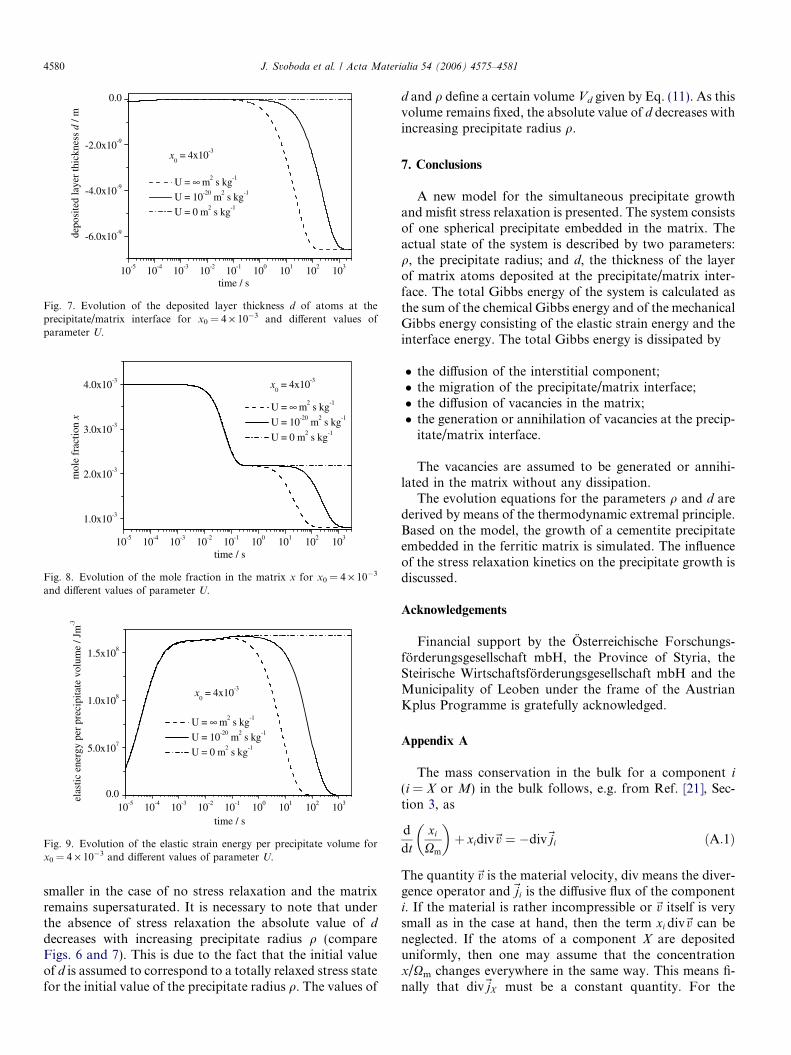
The second series of figures (Figs. 6–9) is plotted for x0 =4 · 10�3 and the same values of U 2 {0,10�20, 1} m2
10-5 10-4 10-3 10-2 10-1 100 101 102 1030.0
5.0x10⁻⁸
1.0x10⁻⁷
1.5x10⁻⁷
2.0x10⁻⁷
2.5x10⁻⁷
prec
pita
te r
adiu
s ρ
/ m
time / s
U = ∞ m2 s kg-1
U = 10-20 m2 s kg-1
U = 0 m2 s kg-1
x0 = 4x10⁻³
Fig. 6. Evolution of the precipitate radius q for x0 = 4 · 10�3 and differentvalues of parameter U.
10-5 10-4 10-3 10-2 10-1 100 101 102 103
0.0
5.0x10⁻⁸
1.0x10⁻⁷
1.5x10⁻⁷
prec
pita
te r
adiu
s ρ
/ m
time / s
U = ∞ m2 s kg-1
U = 10-20 m2 s kg-1
U = 0 m2 s kg-1
x0 = 2x10⁻³
Fig. 2. Evolution of the precipitate radius q for x0 = 2 · 10�3 and differentvalues of the parameter U, describing the activity of sources and sinks forvacancies at the precipitate/matrix interface.
10-5 10-4 10-3 10-2 10-1 100 101 102 103-5.0x10⁻⁹
-4.0x10⁻⁹
-3.0x10⁻⁹
-2.0x10⁻⁹
-1.0x10⁻⁹
0.0
depo
site
d la
yer
thic
knes
s d
/ m
time / s
U = ∞ m2 s kg-1
U = 10-20 m2 s kg-1
U = 0 m2 s kg-1
x0 = 2x10⁻³
Fig. 3. Evolution of the deposited layer thickness d of atoms at theprecipitate/matrix interface for x0 = 2 · 10�3 and different values ofparameter U.
10-5 10-4 10-3 10-2 10-1 100 101 102 1030.0
2.5x10⁷
elas
tic e
nerg
y pe
r p
time / s
U = ∞ m s kg
U = 10-20 m2 s kg-1
U = 0 m2 s kg-1
Fig. 5. Evolution of the elastic strain energy per precipitate volume forx0 = 2 · 10�3 and different values of parameter U.
s kg�1 are used. From the figures one can conclude thatthe chemical driving force is always sufficient for a signifi-cant growth of the precipitate in the first 0.2 s. Then, thefurther growth of the precipitate is significantly influencedby stress relaxation. The final size of the precipitate is
10-5 10-4 10-3 10-2 10-1 100 101 102 103
1.0x10⁻³
2.0x10⁻³
3.0x10⁻³
4.0x10⁻³
mol
e fr
actio
n x
time / s
U = ∞ m2 s kg-1
U = 10-20 m2 s kg-1
U = 0 m2 s kg-1
x0 = 4x10⁻³
Fig. 8. Evolution of the mole fraction in the matrix x for x0 = 4 · 10�3
and different values of parameter U.
10-5 10-4 10-3 10-2 10-1 100 101 102 1030.0
5.0x10⁷
1.0x10⁸
1.5x10⁸
elas
tic e
nerg
y pe
r pr
ecip
itate
vol
ume
/ Jm
-3
time / s
U = ∞ m2 s kg-1
U = 10-20 m2 s kg-1
U = 0 m2 s kg-1
x0 = 4x10⁻³
Fig. 9. Evolution of the elastic strain energy per precipitate volume forx0 = 4 · 10�3 and different values of parameter U.
10-5 10-4 10-3 10-2 10-1 100 101 102 103
-6.0x10⁻⁹
-4.0x10⁻⁹
-2.0x10⁻⁹
0.0
depo
site
d la
yer
thic
knes
s d
/ m
time / s
U = ∞ m2 s kg-1
U = 10-20 m2 s kg-1
U = 0 m2 s kg-1
x0 = 4x10⁻³
Fig. 7. Evolution of the deposited layer thickness d of atoms at theprecipitate/matrix interface for x0 = 4 · 10�3 and different values ofparameter U.
4580 J. Svoboda et al. / Acta Materialia 54 (2006) 4575–4581
smaller in the case of no stress relaxation and the matrixremains supersaturated. It is necessary to note that underthe absence of stress relaxation the absolute value of d
decreases with increasing precipitate radius q (compareFigs. 6 and 7). This is due to the fact that the initial valueof d is assumed to correspond to a totally relaxed stress statefor the initial value of the precipitate radius q. The values of
d and q define a certain volume Vd given by Eq. (11). As thisvolume remains fixed, the absolute value of d decreases withincreasing precipitate radius q.
7. Conclusions
A new model for the simultaneous precipitate growthand misfit stress relaxation is presented. The system consistsof one spherical precipitate embedded in the matrix. Theactual state of the system is described by two parameters:q, the precipitate radius; and d, the thickness of the layerof matrix atoms deposited at the precipitate/matrix inter-face. The total Gibbs energy of the system is calculated asthe sum of the chemical Gibbs energy and of the mechanicalGibbs energy consisting of the elastic strain energy and theinterface energy. The total Gibbs energy is dissipated by
� the diffusion of the interstitial component;� the migration of the precipitate/matrix interface;� the diffusion of vacancies in the matrix;� the generation or annihilation of vacancies at the precip-
itate/matrix interface.
The vacancies are assumed to be generated or annihi-lated in the matrix without any dissipation.
The evolution equations for the parameters q and d arederived by means of the thermodynamic extremal principle.Based on the model, the growth of a cementite precipitateembedded in the ferritic matrix is simulated. The influenceof the stress relaxation kinetics on the precipitate growth isdiscussed.
Acknowledgements
Financial support by the Osterreichische Forschungs-forderungsgesellschaft mbH, the Province of Styria, theSteirische Wirtschaftsforderungsgesellschaft mbH and theMunicipality of Leoben under the frame of the AustrianKplus Programme is gratefully acknowledged.
Appendix A
The mass conservation in the bulk for a component i
(i = X or M) in the bulk follows, e.g. from Ref. [21], Sec-tion 3, as
d
dtxi
Xm
� �þ xidiv~v ¼ �div~ji ðA:1Þ
The quantity~v is the material velocity, div means the diver-gence operator and~ji is the diffusive flux of the componenti. If the material is rather incompressible or~v itself is verysmall as in the case at hand, then the term xi div~v can beneglected. If the atoms of a component X are depositeduniformly, then one may assume that the concentrationx/Xm changes everywhere in the same way. This means fi-nally that div~jX must be a constant quantity. For the

J. Svoboda et al. / Acta Materialia 54 (2006) 4575–4581 4581
spherically symmetric case this is fulfilled by the followingradial component of the flux of component X:
jX ðrÞ ¼ jX ðqþÞ �R3 � r3
R3 � q3� q
2
r2ðA:2Þ
which meets also the boundary condition that jX(R) = 0.The mass conservation at the interface at r = q follows,
e.g. from Ref. [21], Section 3, as
jX ðqþÞ � jX ðq�Þ ¼ ðxðqþÞ=Xm � xðq�Þ=XpÞ _q ðA:3Þ
The radius q+ is on the right side of the interface, q� on theleft side. Since there is no flux inside the precipitate,jX(q�) ” 0 and x(q�) = b. Furthermore we assumex(q+) = x and thus
jX ðqþÞ ¼ ðx=Xm � b=XpÞ _q ðA:4ÞIf the volume rate _V d of the matrix matter is transported tothe precipitate, then jMðqÞ ¼ _V d=4pq2 is the radial flux ofcomponent M at the interface. Analogously to Eq. (A.2)the corresponding radial flux jM(r) is then
�jMðrÞ ¼_V d
4pq2� 1
Xm
� R3 � r3
R3 � q3� q
2
r2ðA:5Þ
which meets also the boundary condition that jM(R) = 0.
References
[1] Svoboda J, Gamsjager E, Fischer FD. Philos Mag Lett 2005;85:473.
[2] Eikum A, Thomas G. Acta Metall 1964;12:537.[3] Liu WJ, Jonas JJ. Mater Sci Technol 1989;5:8.[4] Liu WJ, Jonas JJ. Metall Trans A 1989;20:689.[5] Popov VV, Gorbachev II, Alyabieva JA. Philos Mag 2005;85:2449.[6] Gao X-L. Mech Res Commun 2003;30:411.[7] Zhang LH, Johnson E, Dahmen U. Mater Res Symp Proc 2004;821:
8.[8] Dahmen U, Hagege S, Faudot F, Radetic T, Johnson E. Philos Mag
2004;84:2651.[9] Zhang LH, Johnson E, Dahmen U. Acta Mater 2005;53:3635.
[10] Svoboda J, Turek I, Fischer FD. Philos Mag 2005;85:3699.[11] Umantsev AR, Roitburd AL. Sov Phys Solid State 1988;30:651
[translation of Fiz Tverd Tela 1988;30:1124].[12] Fischer FD, Bohm HJ, Oberaigner ER, Waitz T. Acta Mater
2006;54:151.[13] Svoboda J, Fischer FD, Fratzl P, Kroupa A. Acta Mater
2002;50:1369.[14] Onink M, Ph.D. thesis, Technische Universiteit Delft; 1995.[15] Harste K, Schwerdtfeger K. Mater Sci Technol 1996;12:378.[16] Mizubayashi H, Li SJ, Yumoto H, Shimotoma M. Scripta Mater
1999;40:773.[17] Lee B-J, Oh KH. Z Metallkd 1996;87:195.[18] Agren J. Acta Metall 1982;30:841.[19] Gustafson P. Scand J Metall 1985;19:259.[20] Dinsdale AT. Calphad 1991;15:317.[21] Fischer FD, Simha NK. Acta Mech 2004;171:213.