influence of al interlayer thickness on laser welding of ... added during the welding process. ......
TRANSCRIPT
WELDING RESEARCH
WELDING JOURNAL / OCTOBER 2016, VOL. 95384-s
Introduction Vehicle design and fabrication hasbeen increasingly innovated by automo-tive manufacturers and their suppliersin the effort to maximize fuel efficiencyto meet the new, more stringent fueland emission standards, while main-taining critical safety requirements (Ref.1). To realize this goal, automakers areworking to develop new lightweight ma-terials and integrate them into vehicledesigns. Magnesium alloys have beenconsidered as promising materials forautomotive applications due to theirlow density and high specific strength,
which has drawn considerable attentionin the past few years (Ref. 2). Currently,steel sheets remain the most commonlyused material in the automotive indus-try. They are considered the most cost-effective material for vehicle applica-tions. Therefore, the fabrication of hy-brid lightweight structural componentsof magnesium alloys and steel, becomesa feasible method to further lower thevehicle weight. Reliable joining of Mg tosteel would facilitate the increased useof magnesium alloys and expand thescope of their application in the auto-motive industry. Direct joining of magnesium alloys
to steel was proven to be difficult byconventional fusion welding tech-niques due to a huge difference intheir melting points and Mg-Fe immis-cibility characteristics. The meltingpoint of steel (1450ºC) is higher thanthe boiling point of magnesium(1091ºC), which could cause cata-strophic vaporization of the moltenmagnesium if they melt simultaneous-ly. In addition, the maximum solid sol-ubility of Fe in Mg is only 0.00041 at-%. Their immiscibility and low solidsolubility suggests they do not reactwith each other or mix in the liquidstate at ambient pressure. Thus, met-allurgical bonding between these twomaterials would only be possible if an-other intermediate element that caninteract with or possess substantialsolid solubility with both of them canbe added during the welding process. The feasibility of joining Mg tosteel using various processes, such asfriction stir welding (FSW) (Refs. 3–8),resistance spot welding (RSW) (Refs.9, 10), diffusion bonding (DB) (Refs.11–13), cold metal transfer (CMT)welding (Ref. 14), hybrid laser-arcwelding (Refs. 15–20), and laser weld-ing-brazing or brazing (Refs. 21–27)have previously been investigated. The FSW process has been reportedto successfully realize the bonding ofMg and steel by accelerating the diffu-sion of Al atoms from the Mg basemetal to steel with the combined ef-fect of external force and strong stir-ring. The Fe-Al phase formed, actingas the transitional compound to bond
Influence of Al Interlayer Thickness onLaser Welding of Mg/Steel
The impact of different Al interlayer thicknesses on interfacial reactionsand mechanical properties during laser welding of Mg to steel was investigated
BY C. W. TAN, B. CHEN, X. G. SONG, L. ZHOU, S. H. MENG, L. Q. LI, AND J. C. FENG
ABSTRACT The bonding of immiscible system Mg/steel was facilitated by adding an Al interlayer using laser welding. The influence of the added interlayer thickness on the microstructure andmechanical properties of the dissimilar joints were investigated. The Al interlayer was dissolved into the Mg fusion zone and mutual diffusion with steel, causing metallurgical bonding of Mg and steel at the interface. FeAl reaction layers with different thicknesses wereproduced along the fusion zonesteel interface. Two different reaction layers divided by thethickness of the reaction layer (2 m) were thereafter identified by TEM analysis. The phases formed adjacent to the steel substrate were Fe(Al) solid solution and Al8(Mn, Fe)5 phaseon the Fe(Al) surface, while the Al6Fe phase formed when the reaction layer was more than2 m. Three different fracture modes were distinguished from all the joints, which wasclosely associated with the interfacial reaction. Insufficient atomic diffusion caused interfacial failure. Fracture occurred in the fusion zone when the thickness of the Al interlayer was0.2–0.5 mm. The maximum value of the tensileshear fracture load reached 133 N/mm,which represented 40.3% joint efficiency with respect to the steel base metal. However, theexcessive interfacial reaction resulted in cracking at the interface and a greater amount ofbrittle MgAl compounds, giving rise to decreased mechanical properties.
KEYWORDS • Laser Welding • Dissimilar Metals • Magnesium Alloy • Microstructure • Mechanical Properties
C. W. TAN ([email protected]), B. CHEN, X. G. SONG ([email protected]), L. ZHOU, and S. H. MENG are with the Shandong Provincial Key Laboratory of Special Welding Technology, Harbin Institute of Technology at Weihai, Weihai, China. TAN, L. Q. LI, and J. C. FENG arewith the State Key Laboratory of Advanced Welding and Joining, Harbin Institute of Technology, Harbin, China.
TAN SUPP OCT 2016_Layout 1 9/14/16 3:17 PM Page 384

WELDING RESEARCH
OCTOBER 2016 / WELDING JOURNAL 385-s
Mg and steel. The results achieved us-ing RSW showed low interplanar mis-matching of Fe2Al5/Fe (0%) andFe2Al5/Mg (4.8%) heterophase inter-faces, indicating the Fe-Al phase couldact as an interlayer between Mg andFe. However, without external force,utilizing various interlayers has beenthe main way to solve the metallurgi-cal bonding problems of Mg/steel. Thebenefits of using different interlayersand elements, such as Cu, Ni, Sn, Zn,and Al-12Si, have been explored.Elthalabawy and Khan (Refs. 11, 12)tried to join Mg to steel using diffu-sion bonding (transient liquid bond-ing), in which the Cu and Ni interlay-ers were used. Solid-state diffusion,eutectic formation, and the formationof ternary intermetallic compoundswere observed at the interface. The in-terfacial reaction was intense in theliquid state, inducing the excessive for-mation of brittle and thick layers,which was detrimental to the jointstrength. Cao et al. (Ref. 14) investigated thefeasibility of CMT welding of Mg togalvanized mild steel. The Zn coatingwas found to promote the wetting ofthe AZ61 filler metal on the steel sur-face. A sound CMT welded Mg/coatedsteel joint was obtained with the jointstrength comparable to a Mg-Mg fu-sion joint.
Laser welding(brazing), as an alter-native advancedwelding technique,has received consid-erable attentiondue to its potentialfor flexible joiningof dissimilar met-als. Liu et al. (Refs.15–17, 20) used hy-brid laser-arc weld-ing to bond Mg andsteel with Cu, Ni,and Sn interlayers,respectively. Thesethin interlayerswere placed in between upper Mg andlower steel sheets. Typically, laser withlow power penetrated from the Mgsheet and the interlayer into the lowersteel sheet. These added interlayerswere heated and melted to react withMg and steel, resulting in the forma-tion of a transitional layer in the fu-sion zone and solid solution close tothe steel side. The tensile-shearstrength was improved because thebonding status was changed from me-chanical bonding to semimetallurgicalbonding. A severe evaporation of theupper Mg base metal occurred duringthe process, which limited the applica-tion of this welding technique. In addition, Wahba and Katayama(Ref. 21) also reported the desirable
joint could be achieved with the pres-ence of Zn coating on the steel surfaceusing laser conduction welding. To minimize the vaporization ofMg sheet and improve welding flexibil-ity, laser brazing with a preset Mg-based filler was employed. Various in-terlayers, including Al-12Si (Ref. 24),Ni (Ref. 26), and Sn (Ref. 27), wereused. When using an Al-12Si coating,formation of -Fe(Al,Si)3 was observedalong the fusion zone-steel interface.In the case of the Ni interlayer, forma-tion of Fe(Ni) solid solution on thesteel surface was found to be the keyfor metallurgical bonding of Mg/steelimmiscible systems. The joint strengthwas reported to be higher than thatwelded with Al coated steel. After-ward, they selected another viable in-
Fig. 1 — Schematic of laser welding and the testing specimen: A — Laser welding process of Mg to steel; B — tensileshear testspecimen.
Fig. 2 — Weld appearances of Mg/steel joints produced with different thicknesses of Al interlayers: A — 0.1 mm; B — 0.3 mm;C — 0.5 mm; and D — 0.7 mm.
A A
B
C
D
B
TAN SUPP OCT 2016_Layout 1 9/14/16 3:17 PM Page 385

WELDING RESEARCH
WELDING JOURNAL / OCTOBER 2016, VOL. 95386-s
terlayer, Sn, following a review of bina-ry and ternary phase diagrams. The re-sults suggested that all tensile-shearspecimens fractured in the steel basemetal. The fracture load far exceededthat achieved with the former twokinds of interlayers. The Sn coatingwas reported to promote wetting be-tween the molten filler metal and steelsheet, creating an oxide-free steel sur-face for metallurgical bonding. Forma-tion of the Fe(Al) solid solution andAl8(Mn, Fe)5 on the Fe(Al) surface,with their low interplanar mismatch,was mainly responsible for high jointstrength. Therefore, selection of an appropri-ate intermediate alloying element forjoining Mg to steel was vital for enhanc-ing good wetting-spreading ability andinterfacial bonding between the fusionzone and steel without producing toothick brittle reaction layers. In our pre-vious studies, the influence of differentcoating surfaces (Refs. 28, 29) and alloy-ing elements from filler metal and steel(Refs. 30–32) have been investigated.The important finding was that the Alelement, as a key element diffusingfrom the filler metal into the interface,was accelerated and induced by thechemical potential, resulting in metal-lurgical bonding of the Mg/steel inter-face. The Fe-Al phase formed at theMg/steel interface was expected to be
favorable for the mechanical propertiesafter the aforementioned studies. In the present work, the Al interlay-er was employed as the transitional in-terlayer, which was expected to inducethe Fe-Al reaction after melting andproduce the Fe-Al phase to realizemetallurgical bonding of Mg/steel.The aim of this study was to investi-gate the influence of different Al inter-layer thicknesses on interfacial reac-tions and mechanical properties dur-ing laser welding of Mg to steel. Themicrostructure characteristics wereobserved and identified. The mechani-cal properties were evaluated. Finally,the bonding mechanism was expectedto be elucidated.
Experimental Procedures
Selected as the base metals were1.5-mm-thick AZ31B Mg alloy (Mg-3Al-1Zn-0.2Mn, wt%) and 1-mm-thickQ235 mild steel (0.17C-0.7Mn-0.35Si-
0.035S-0.035P). The sheets were cutinto rectangular strips 30 mm wideand 100 mm long. The size of the Alinterlayer used in the present workwas 3 mm wide and 100 mm long, sothe Al interlayer could totally melt andreact with the Mg or steel sheets. Be-fore welding, the surfaces of the Mg al-loy and steel sheets were cleaned withabrasive paper to remove surface ox-ides, and then cleaned in acetone andother contaminants from the surfaces. A fiber laser system with a maxi-mum power of 10 kW (IPG YLR-10000) and a KUKA six-axis robotwere used in this study. The laserbeam had a wavelength of 1070 nmand beam parameter product of 7.2mm mrad. It was transmitted by a200-μm core-diameter fiber and fo-cused by a 200-mm lens to obtain aspot size of 0.2 mm. Figure 1 shows the schematic oflaser welding. The experiments werecarried out in a lap joint configurationwith the Mg sheet clamped on the
Fig. 3 — Cross sections of Mg/steel joints produced with different thicknesses of Al interlayers: A — 0.1 mm; B — 0.2 mm; C — 0.3 mm; D — 0.4 mm; E — 0.5 mm; and F — 0.7 mm.
Table 1 — STEMEDS Results of Points Indicated in Fig. 7 (at%)
Positions Mg Al Mn Fe
P1 95.8 3.8 0.4 — P2 52.6 27.1 13.0 7.3 P3 — 5.5 — 94.5
A B C
D E F
TAN SUPP OCT 2016_Layout 1 9/14/16 3:17 PM Page 386

WELDING RESEARCH
OCTOBER 2016 / WELDING JOURNAL 387-s
steel sheet. The laser beam was irradi-ated on the surface of the AZ31B Mgalloy vertically. Argon shielding gaswas provided at a flow rate of 20 L/min to prevent oxidation. The laserbeam was defocused to irradiate alarge area. The process parameters em-ployed in the study were as follows:laser power 800 W, welding speed 0.3m/min, and defocused distance +20mm. After laser welding, typical crosssections of the welded specimens werecut and mounted in epoxy resin. Stan-dard grinding and polishing prepara-tion procedures were then utilized.The appearances and cross sectionswere observed using an optical micro-scope (OM). The reaction layer at the
interface between the fusion zone andsteel were observed using scanningelectron microscopy (SEM) in back-scattered electron (BSE) mode. A transmission electron microscopy(TEM) foil of the bonded region wasprepared using the focused ion beam(FIB) technique. The preparation forthe FIB-TEM specimen was made us-ing an in-situ lift out method. TheTEM with a Tecnai-G2 F30 operatingat a nominal voltage of 300 kV wasused to characterize the microstruc-ture in detail. Phase identification was investigat-ed by selected-area electron diffraction(SAED) combined with energy-disper-sive spectroscopy (EDS) in scanningtransmission electron microscopy
(STEM) mode. A Vickers hardnessmeasurement was performed acrossthe fusion zone-steel interface and fu-sion zone adjacent to the interface, re-spectively. A test load of 0.1 Kgf and adwell time of 10 s were utilized. Thetensile-shear tests were performed atroom temperature using an Instron5569 at a crosshead speed of 1 mm/min. Shims were clamped to each end ofthe specimens to ensure shear loads inthe lap joint while minimizing bendingor torque of the specimens. Jointstrength was calculated via the tensiletesting of at least three specimens, andthe average was reported with the stan-dard deviation provided via error bars.
A B
C D
Fig. 4 — Microstructure morphologies of interfacial reaction layers with different thicknesses of Al interlayers: A — 0.1 mm; B — 0.3 mm;C — 0.5 mm; and D — 0.7 mm.
TAN SUPP OCT 2016_Layout 1 9/14/16 3:17 PM Page 387

WELDING RESEARCH
WELDING JOURNAL / OCTOBER 2016, VOL. 95388-s
Results and Discussion
Joint Appearances
Figure 2 shows the joint appearanceswith different Al interlayer thicknesses.No spatter or obvious defect was evi-denced in the figure because of suitableheat input employed in the presentwork. However, a nonuniform andrough surface was first observed whenthe interlayer was thin, as shown in Fig.2A and 2B. It was mainly attributed tothe instability of the Mg molten pool atthe action of laser energy. With the in-crease of Al thickness, the joint surfacewas improved, obtaining a smooth anduniform appearance indicated in Fig. 2Cand 2D.
From the cross-sectional viewsshown in Fig. 3, the Al foil was not ob-served as a separate layer along the in-terface after the process, indicating itentirely melted and was dissolved intothe Mg liquid adjacent to the interface.The opening was observed at the edgeof the fusion zone close to the steel in-terface due to the bad wetting-spread-ing ability of Mg and steel. The open-ing defect was improved with the addi-tion of Al foil. With an increasingthickness of the interlayer, the jointwidth became larger due to good wet-ting of Al and steel. It was believedthat the affinity of Al and Fe was muchstronger than that of Mg and Fe. Thus,the thin Al liquid adhering to the steelinterface reduced the difficulty of theMg molten pool spreading on the steel
surface. Good wetting-spreading abili-ty of Al on the steel surface led tomore flowability, as demonstrated inFig. 3E and F.
Microstructural Analysis
Figure 4 shows microstructure mor-phologies along the fusion zone-steelinterface with different thicknesses ofthe Al interlayer. Formation of the in-terfacial reaction layer was observedfrom all the joints, confirming metal-lurgical bonding of the immiscible Mgand Fe was realized by adding the Alinterlayer. In addition, the thickness of the Fe-Al reaction layer formed at the inter-face was found to increase with the in-creasing Al interlayer. When the thick-ness of the Al interlayer was 0.1 mm,no obvious reaction layer was noticed,even at higher magnification as shownin Fig. 4A, suggesting most of the Alinterlayer melted and was mixed withthe molten Mg fusion zone immedi-ately near the interface. The reactionlayer was evidently observed when in-creasing the thickness of the Al inter-layer to 0.3 mm. These reaction prod-ucts exhibited nonuniform and facetedmorphology. With a further increaseof the Al interlayer to 0.7 mm, the re-action layer grew dramatically, reach-ing its thickness of more than 10 m. The crack was evidently observed ata higher magnification indicated in theinset of Fig. 4D, which deterioratedjoint strength. The results were in ac-cordance with the previous report thatcracking may easily occur if the thick-ness of the Fe-Al intermetallic layersexceeded 10 m, which was detrimen-tal to mechanical properties (Ref. 33). EDS line scanning analyses wereperformed to obtain concentrationprofiles of the main alloying elementsacross the interface between the Mgfusion zone and steel. Figure 5 showsthe corresponding line scan results.The Mg element decreased graduallyfrom the fusion zone to the steel side,while the Fe content was varied in anopposite way. Note that an apparentAl concentration peaked at the inter-face in all joints, indicating an occur-rence of atomic diffusion or dissolu-tion of the Al element, which there-after induced interfacial reaction. Ad-ditionally, the diffusion distance be-came longer with the increasing Al
Fig. 5 — EDS line scan results of Mg, Al, Fe, and Mn across the fusion zonesteel interfaceat different thicknesses of the Al interlayer: A — 0.1 mm; B — 0.2 mm; and C — 0.3 mm.
A
B
C
TAN SUPP OCT 2016_Layout 1 9/14/16 3:17 PM Page 388
WELDING RESEARCH
OCTOBER 2016 / WELDING JOURNAL 389-s
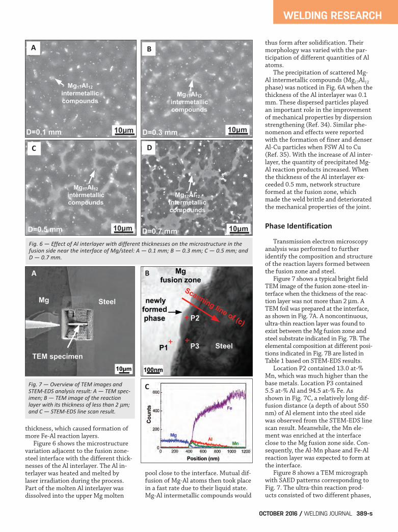
thickness, which caused formation ofmore Fe-Al reaction layers. Figure 6 shows the microstructurevariation adjacent to the fusion zone-steel interface with the different thick-nesses of the Al interlayer. The Al in-terlayer was heated and melted bylaser irradiation during the process.Part of the molten Al interlayer wasdissolved into the upper Mg molten
pool close to the interface. Mutual dif-fusion of Mg-Al atoms then took placein a fast rate due to their liquid state.Mg-Al intermetallic compounds would
thus form after solidification. Theirmorphology was varied with the par-ticipation of different quantities of Alatoms. The precipitation of scattered Mg-Al intermetallic compounds (Mg17Al12
phase) was noticed in Fig. 6A when thethickness of the Al interlayer was 0.1mm. These dispersed particles playedan important role in the improvementof mechanical properties by dispersionstrengthening (Ref. 34). Similar phe-nomenon and effects were reportedwith the formation of finer and denserAl-Cu particles when FSW Al to Cu(Ref. 35). With the increase of Al inter-layer, the quantity of precipitated Mg-Al reaction products increased. Whenthe thickness of the Al interlayer ex-ceeded 0.5 mm, network structureformed at the fusion zone, whichmade the weld brittle and deterioratedthe mechanical properties of the joint.
Phase Identification
Transmission electron microscopyanalysis was performed to furtheridentify the composition and structureof the reaction layers formed betweenthe fusion zone and steel. Figure 7 shows a typical bright fieldTEM image of the fusion zone-steel in-terface when the thickness of the reac-tion layer was not more than 2 m. ATEM foil was prepared at the interface,as shown in Fig. 7A. A noncontinuous,ultra-thin reaction layer was found toexist between the Mg fusion zone andsteel substrate indicated in Fig. 7B. Theelemental composition at different posi-tions indicated in Fig. 7B are listed inTable 1 based on STEM-EDS results. Location P2 contained 13.0 at-%Mn, which was much higher than thebase metals. Location P3 contained5.5 at-% Al and 94.5 at-% Fe. Asshown in Fig. 7C, a relatively long dif-fusion distance (a depth of about 550nm) of Al element into the steel sidewas observed from the STEM-EDS linescan result. Meanwhile, the Mn ele-ment was enriched at the interfaceclose to the Mg fusion zone side. Con-sequently, the Al-Mn phase and Fe-Alreaction layer was expected to form atthe interface. Figure 8 shows a TEM micrographwith SAED patterns corresponding toFig. 7. The ultra-thin reaction prod-ucts consisted of two different phases,
Fig. 6 — Effect of Al interlayer with different thicknesses on the microstructure in thefusion side near the interface of Mg/steel: A — 0.1 mm; B — 0.3 mm; C — 0.5 mm; andD — 0.7 mm.
Fig. 7 — Overview of TEM images andSTEMEDS analysis result: A — TEM specimen; B — TEM image of the reactionlayer with its thickness of less than 2 m;and C — STEMEDS line scan result.
A
A B
B
C
C
D
TAN SUPP OCT 2016_Layout 1 9/14/16 3:17 PM Page 389

WELDING RESEARCH
WELDING JOURNAL / OCTOBER 2016, VOL. 95390-s
as shown in Fig. 8A. The phases close to the steel sub-strate were found to be continuousand uniform followed by noncontinu-ous phases toward the fusion zone.The nonuniform phases close to thefusion zone were identified as Al8Mn5,while some Fe element was also de-tected. Therefore, the Al8(Mn,Fe)5 in-termetallic compound was exactly in-dexed, in which some Mn atoms werereplaced by Fe atoms because theatomic radius of Mn (0.112 nm) andFe (0.124 nm) were close (Ref. 27).The phase adjacent to the steel sub-strate was indexed by TEM and identi-fied as Fe(Al) solid solution with abody-centered cubic (BCC) crystalstructure, respectively. The SAED wastaken along the [111] zone axis of thephase. These findings were consistentwith the observation of the interfacialreaction layer when laser brazing Mgto Sn coated steel sheet (Ref. 27). To prove the degree of solid solu-tion Al in Fe, the interatomic misfitand interplanar mismatch betweentwo phases can be calculated by
where |a – a0| is the difference be-tween interatomic or interplanar spac-
ings of the two phases and a0 is the in-teratomic or interplanar spacing of thesteel substrate. The a0 was 0.287 nm.The misfit was 4.2%; it reduced to0.5% with the distance from the steelinterface of 2000 nm after calculation.The results corresponded to the longdiffusion of Al into the steel substrateobtained in Fig. 7C. Figure 9 shows TEM images takenat the fusion zone-steel interface whenthe thickness of reaction products wasmore than 2 m. The reaction layerwas clearly evidenced at the interface.The relatively thick Al interlayer melt-ed, providing more Al atoms at the in-terface, making the atomic number ofAl dominate in the whole Fe-Al sys-tem. As a result, it was possible thatthe Al-rich Al-Fe intermetallic com-pound formed, rather than solid solution. High magnification of the TEM im-age at the interface indicated the reac-tion layer was distinctly different fromthe fusion zone and steel as shown inFig. 10B. Combined with the EDS andSAED calibration results, the Al6Fephase with orthorhombic structure wasidentified. The metastable state Al6Fewas precipitated at the temperature ofabout 820ºC under the condition of therapid thermal cycle. In addition, theMg17Al12 intermetallic compounds alsoexisted adjacent to the interface, corre-
sponding to the observation of SEMmorphology in Figs. 4 and 6.
Mechanical Properties
Figure 11 shows Vickers hardnessdistribution profiles across the inter-face and near the fusion zone. The hardness distribution acrossthe fusion zone/steel interface withthe Al thickness of 0.2 mm was meas-ured, and the result is shown in Fig.11A. The average hardness of the fu-sion zone and steel substrate was ap-proximately 100 and 209 HV, respec-tively. Note that an abrupt change inthe hardness value at the interface wasnoticed, which was higher than the fu-sion zone and neighboring steel sub-strate, reaching the maximum value of587 HV. The distinct rise in the hard-ness at the interface was closely asso-ciated with the presence of interfacialreaction products corresponding tothe observation in Fig. 4. Figure 11B presents the hardnessdistribution profile at the fusion zonenear the interface. The hardness of theAZ31 Mg alloy base metal was about60 HV when without Al foil. The thick-er the added Al interlayer, the higherthe hardness close to the fusion zone.It was evident that the hardness in-creased toward the interface due tothe precipitation of more Mg-Al compounds. Figure 12 shows the tensile-shearfracture load of the laser welded mag-nesium-steel joints and the thicknessof the reaction layer with the variationof thicknesses of the Al interlayer andthe fracture load with a function ofthickness of reaction layer. The jointstrength was given here as fractureload because it had both tensile andshear stresses during tests. Three dif-ferent fracture modes were distin-guished in the present work. The frac-ture behavior depended upon the in-terfacial bonding force and brittlenessof the fusion zone. The fracture loadof the joint produced with an Al thick-ness of no more than 0.1 mm wasquite low, resulting in interfacial fail-ure. The interfacial bonding was weakdue to insufficient atomic diffusion orinterfacial reaction. Fracture occurred at the fayingsurface of the Mg and steel sheets.With increasing thickness of the Alinterlayer (0.2–0.5 mm), the thick-
� =a�a0
a0�100%
Fig. 8 — TEM bright field image and SAED patterns corresponding to Fig. 7: A — TEM micrograph; B–D — SAED patterns of interfacial phases.
-
A B
C
D
-
TAN SUPP OCT 2016_Layout 1 9/14/16 3:17 PM Page 390

ness of the reaction layer formed atthe interface was 2.3–5.7 m. Thefracture load was enhanced to maxi-mum value of 133 N/mm, which rep-resented 40.3% joint efficiency withrespect to the mild steel base metal,as shown in Fig. 11B. Joint efficiency was calculated bycomparing the maximum load of thejoint when fractured in lap shear ten-
sile testing with the maximum load-carrying capacity of the weaker basesheet section. The calculated joint effi-ciency was reported in a previousstudy (Ref. 30). In this case, the frac-ture location was at the Mg fusionzone, indicating the Mg/steel interfacewas not the weak point. Compared to high interfacial bond-ing, the brittle precipitated Mg-Al in-termetallic compounds made the cracktend to initiate and propagate at thefusion zone. The fracture load de-creased sharply with further increasingthe thickness of the Al interlayer. Thecrack formed in between the interfaceof the Fe-Al reaction layer and steelsubstrate, which became the weakestpart of the joint despite the presenceof brittle Mg-Al compounds in the fu-sion zone close to the interface.
Figure 13 presents the fracture sur-face morphologies of joints welded atdifferent thicknesses of the Al inter-layer. For the joint with interfacial fail-ure mode, some residual Mg fusionzone was attached to the steel sub-strate, as shown in Fig. 13A. Highermagnification indicated the fracturesurface was characterized by the tear-ing ridge — Fig. 13B. When the joint fractured at the Mgfusion zone, the fracture surface exhib-ited dimples together with some cleav-age-like flat facets demonstrated in Fig.13D, which was similar to the observa-tion of Mg-Mg fusion welding (Ref. 36).The flat surface suggested brittleness ofthe Mg-Al intermetallic compounds inthe fusion zone. It was believed that themore brittle the microstructure, theflatter the fracture surface. With the in-creasing thickness of the reaction layer,the fracture was found to occur alongthe interface between the reaction layerand steel substrate due to the presenceof cracks formed in between them afterthe process. Smooth fracture surface withoutadequate plastic deformation was ob-served on the steel side, as shown inFig. 13E. Cracking was noticed at thehigher magnification arrowed in theinset of Fig. 13E. Remnants of the fu-sion zone adhering to the fracture sur-face shown in Fig. 13F were found tobe more brittle compared to the resultin Fig. 13D.
Bonding Mechanism
Based on the analyses above, thebonding mechanism of Mg to steel
WELDING RESEARCH
OCTOBER 2016 / WELDING JOURNAL 391-s
Fig. 9 — Diffraction patterns of the FeAl phase at different locations of 0, 100, and 2000 nm with the point indicated in Fig. 8.
Fig. 10 — TEM bright field image and SAEDpatterns obtained when the thickness of thereaction layer was more than 2 m: A–B —TEM micrograph; C — SAED patterns of theinterfacial phases indicated in B.
A
A
B
B
C
C
TAN SUPP OCT 2016_Layout 1 9/14/16 3:17 PM Page 391

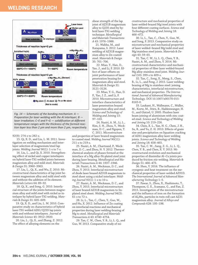
with the addition of the Al interlayerwas elucidated. Figure 14 shows the schematic dia-gram of the joining mechanism. First,melting of the Mg sheet and Al inter-layer occurred simultaneously whensuffering the laser beam irradiation, asshown in Fig. 14B. The liquid Mgatoms and Al atoms dissolved intoeach other. At the same time, some Alatoms close to the liquid/solid inter-face diffused into the steel surface. Because of the laser irradiation, theatoms in the steel adjacent to the in-terface were also activated at a hightemperature and slightly dissolvedinto the liquid. The diffusion distancewas relatively short due to fast ther-mal cycle during laser welding. As a re-sult, different percents of the main al-loying elements Mg, Al, and steel weremixed from fusion zone to theliquid/solid interface. The differentprecipitation modes were distin-guished with the variation of thethick-ness of the Al interlayer. Upon cooling, as the temperature de-creased to about 1000ºC, the solid solu-bility of Al in Fe at the solid/liquid inter-
face was saturated inducing crystalliza-tion of Fe(Al) when the Al interlayerwas very thin, as indicated in Fig. 14C. Athin layer of Fe(Al) formed first fromthe liquid by solid-state diffusion of Alatoms in the liquid filler metal into thesteel. Upon further cooling, some Mnatoms diffusing from the steel substratewere then bonded with Al atoms, givingrise to the Al8Mn5 phase under the tem-perature of 680ºC (Ref. 37). The phase nucleated and grew onthe first precipitated Fe(Al) surface, asshown in Fig. 14D. Part of the Mnatoms were replaced by the Fe atomsdue to their similar atomic radius andmetallurgical characteristics. Whenthe temperature decreased to 650ºC orbelow, -Mg first precipitated fromthe remaining liquid. Finally, a eutectic reaction occurredin the liquid, producing a eutecticstructure ( – Mg + Mg17Al12). In thecase of the thick Al interlayer, more Alatoms segregated at the front of liq-uid/solid interface. Therefore, differ-ent Fe-Al phases formed depending onthe ratio of Al and Fe atoms. The con-tent of Al and Fe reached the stoichio-
metric composition of Al6Fe, whichwas precipitated when the tempera-ture decreased to 820ºC. Some of theFe atoms were replaced by a smallamount of Mn atoms diffusing fromthe steel. After that, the eutectic struc-ture was produced in the molten pool,which was much denser than thatformed with the thin Al interlayer.
Conclusion 1) With the addition of the Al inter-layer, successful joining of Mg to steelwas realized by laser welding. A visuallyacceptable and uniform joint wasachieved with the assistance of a goodaffinity of Al and steel. The best jointquality was obtained using the followingprocess parameters: 800-W laser power,0.3-m/min welding speed, +20-mm de-focused distance, and 0.3-mm-thicknessof Al interlayer. 2) Al interlayer was dissolved intothe Mg fusion zone and mutual diffu-sion with steel, causing metallurgicalbonding of Mg and steel at the inter-face, and more precipitation of the Mg-Al compounds. A reaction layer formedalong the interface of the fusion zone-steel joint. The thickness increased withan increasing thickness of the Al inter-layer. Cracking was observed betweenthe reaction products and steel sub-strate when the thickness was largerthan 10 m. Precipitation of the Mg-Alintermetallic compounds was noticed atthe fusion zone close to the interface.The quantity of the compounds in-creased with the increase of the Al inter-layer. The excessive precipitation causedthe brittleness of the fusion zone anddecreased the fracture load. 3) Two different reaction layers wereidentified by TEM analysis. When thethickness of the reaction layer was lessthan 2 m, the phases close to the steelsubstrate were the Fe(Al) solid solutionand Al8(Mn, Fe)5 phase on the Fe(Al)surface, while the Al6Fe phase formedwhen the reaction layer was more than2 m. 4) Three different fracture modeswere distinguished from all the jointsproduced with different thicknesses ofthe Al interlayers, which was closely as-sociated with the interfacial reaction.Insufficient atomic diffusion caused in-terfacial failure with the fracture at thefaying surface of the Mg and steel sheet.The suitable interfacial reaction oc-
WELDING RESEARCH
WELDING JOURNAL / OCTOBER 2016, VOL. 95392-s
Fig. 11 — Hardness distribution profile: A — Across the interface of Mg/steel; B — near theinterface with the different thicknesses of the Al interlayer.
Fig. 12 — Tensileshear fracture load of the laser welded magnesiumsteel joints: A —Fracture load and thickness of the reaction layer with the variation of thicknesses of the Alinterlayer; B — fracture load with a function of the thickness of the reaction layer.
A B
A B
TAN SUPP OCT 2016_Layout 1 9/14/16 3:17 PM Page 392

curred when the thickness of the Al in-terlayer was 0.2–0.5 mm, resulting infusion zone fracture. The maximum val-ue of tensile-shear fracture load reached133 N/mm, which represented 40.3%joint efficiency with respect to the steelbase metal. However, the excessive in-terfacial reaction resulted in the crack-ing at the interface and greater amountof brittle Mg-Al compounds, giving riseto decreased mechanical properties.
The authors wish to acknowledgesupport from the National Natural Sci-
ence Foundation of China (No.51504074 and 51405099), NaturalScience Foundation of ShandongProvince, China (No. BS2015ZZ008),and China Postdoctoral Science Foun-dation (No. 2015M571406).
1. Schubert, E., Klassen, M., Zerner, I.,Walz, C., and Sepold, G. 2001. Light-weight structures produced by laser beamjoining for future applications in automo-bile and aerospace industry. Journal ofMaterials Processing Technology 115: 2–8. 2. Mordike, B., and Ebert, T. 2001. Mag-
nesium: Properties — applications — po-tential. Materials Science and Engineering: A302: 37–45. 3. Liyanage, T., Kilbourne, J., Gerlich, A.P., and North, T. H. 2009. Joint formationin dissimilar Al alloy/steel and Mg alloy/steel friction stir spot welds. Science andTechnology of Welding and Joining 14:500–508. 4. Schneider, C., Weinberger, T., Inoue,J., Koseki, T., and Enzinger, N. 2011.Characterisation of interface ofsteel/magnesium FSW. Science and Tech-nology of Welding and Joining 16: 100–107. 5. Santella, M., Brown, E., Pozuelo, M.,Pan, T. Y., and Yang, J. M. 2012. Details ofMg-Zn reactions in AZ31 to galvanisedmild steel ultrasonic spot welds. Scienceand Technology of Welding and Joining 17:219–224. 6. Chen, Y. C., and Nakata, K. 2010. Ef-fect of surface states of steel on mi-crostructure and mechanical properties oflap joints of magnesium alloy and steel byfriction stir welding. Science and Technolo-gy of Welding and Joining 15: 293–298. 7. Jana, S., Hovanski, Y., and Grant, G.J. 2010. Friction stir lap welding of mag-nesium alloy to steel: A preliminary inves-tigation. Metallurgical and Materials Trans-actions A 41: 3173–3182. 8. Wei, Y., Li, J., Xiong, J., Huang, F.,and Zhang, F. 2012. Microstructures andmechanical properties of magnesium alloyand stainless steel weld-joint made byfriction stir lap welding. Materials & De-sign 33: 111–114. 9. Liu, L., Xiao, L., Feng, J., Li, L., Es-maeili, S., and Zhou, Y. 2011. Bonding ofimmiscible Mg and Fe via a nanoscaleFe2Al5 transition layer. Scripta Materialia65: 982–985. 10. Liu, L., Xiao, L., Chen, D. L., Feng,J. C., Kim, S., and Zhou, Y. 2013. Mi-crostructure and fatigue properties ofMg-to-steel dissimilar resistance spotwelds. Materials & Design 45: 336–342. 11. Elthalabawy, W. M., and Khan, T. I.2010. Eutectic bonding of austeniticstainless steel 316L to magnesium alloyAZ31 using copper interlayer. The Interna-tional Journal of Advanced ManufacturingTechnology 55: 235–241. 12. Elthalabawy, W. M., and Khan, T. I.2010. Microstructural development ofdiffusion-brazed austenitic stainless steelto magnesium alloy using a nickel inter-layer. Materials Characterization 61:703–712. 13. Elthalabawy, W., and Khan, T.2011. Liquid phase bonding of 316Lstainless steel to AZ31 magnesium alloy.Journal of Materials Science & Technology27: 22–28. 14. Cao, R., Yu, J. Y., Chen, J. H., andWang, P.-C. 2013. Feasibility of cold-met-al-transfer welding magnesium AZ31 togalvanized mild steel. Welding Journal
WELDING RESEARCH
OCTOBER 2016 / WELDING JOURNAL 393-s
Fig. 13 — Fracture surfaces morphologies of the Mg/steel joints at different fracture modes:A, C, and E — Overviews of the fracture surface showing different fracture modes; B, D, andF — higher magnification of the area indicated by B, D, and F, respectively.
Acknowledgments
References
A
C
E F
D
B
TAN SUPP OCT 2016_Layout 1 9/14/16 3:17 PM Page 393
92(9): 274-s to 282-s. 15. Qi, X. D., and Liu, L. M. 2011. Inves-tigation on welding mechanism and inter-layer selection of magnesium/steel lapjoints. Welding Journal 90(1): 1-s to 7-s. 16. Liu, L., and Qi, X. 2010. Strengthen-ing effect of nickel and copper interlayerson hybrid laser-TIG welded joints betweenmagnesium alloy and mild steel. Materials& Design 31: 3960–3963. 17. Liu, L., Qi, X., and Wu, Z. 2010. Mi-crostructural characteristics of lap joint be-tween magnesium alloy and mild steel withand without the addition of Sn element.Materials Letters 64: 89–92. 18. Qi, X., and Song, G. 2010. Interfa-cial structure of the joints between magne-sium alloy and mild steel with nickel as in-terlayer by hybrid laser-TIG welding. Mate-rials & Design 31: 605–609.
19. Qi, X. D., and Liu, L. M. 2010. Com-parative study on characteristics of hybridlaser-TIG welded AZ61/Q235 lap jointswith and without interlayers. Journal ofMaterials Science 45: 3912–3920.
20. Liu, L., Qi, X., and Zhang, Z. 2012.The effect of alloying elements on the
shear strength of the lapjoint of AZ31B magnesiumalloy to Q235 steel by hy-brid laser-TIG weldingtechnique. Metallurgicaland Materials TransactionsA 43: 1976–1988.
21. Wahba, M., andKatayama, S. 2012. Laserwelding of AZ31B magne-sium alloy to Zn-coatedsteel. Materials & Design35: 701–706.
22. Miao, Y., Han, D.,Yao, J., and Li, F. 2010. Ef-fect of laser offsets onjoint performance of laserpenetration brazing formagnesium alloy and steel.Materials & Design 31:3121–3126.
23. Miao, Y. G., Han, D.F., Yao, J. Z., and Li, F.2010. Microstructure andinterface characteristics oflaser penetration brazedmagnesium alloy and steel.Science and Technology ofWelding and Joining 15:97–103.
24. Nasiri, A. M., Li, L.,Kim, S. H., Zhou, Y., Weck-man, D. C., and Nguyen, T.C. 2011. Microstructure
and properties of laser brazed magnesiumto coated steel. Welding Journal 90(11):211-s to 219-s. 25. Nasiri, A. M., Chartrand, P., Weck-man, D. C., and Zhou, N. Y. 2012. Thermo-chemical analysis of phases formed at theinterface of a Mg alloy-Ni-plated steel jointduring laser brazing. Metallurgical and Ma-terials Transactions A 44: 1937–1946. 26. Nasiri, A. M., Weckman, D. C., andZhou, Y. 2013. Interfacial microstructureof diode laser brazed AZ31B magnesium tosteel sheet using a nickel interlayer. Weld-ing Journal 92(1): 1-s to 10-s. 27. Nasiri, A. M., Weckman, D. C., andZhou, Y. 2015. Interfacial microstructureof laser brazed AZ31B magnesium to Sn-plated steel sheet. Welding Journal 94(3):61-s to 72-s. 28. Li, L., Tan, C., Chen, Y., Guo, W.,and Hu, X. 2012. Influence of Zn coatingon interfacial reactions and mechanicalproperties during laser welding-brazing ofMg to steel. Metallurgical and MaterialsTransactions A 43: 4740–4754. 29. Tan, C. W., Chen, Y. B., Li, L. Q., andGuo, W. 2013. Comparative study of mi-
crostructure and mechanical properties oflaser welded-brazed Mg/steel joints withfour different coating surfaces. Science andTechnology of Welding and Joining 18:466–472. 30. Li, L., Tan, C., Chen, Y., Guo, W.,and Song, F. 2013. Comparative study onmicrostructure and mechanical propertiesof laser welded–brazed Mg/mild steel andMg/stainless steel joints. Materials & De-sign 43: 59–65. 31. Tan, C. W., Li, L. Q., Chen, Y. B.,Nasiri, A. M., and Zhou, Y. 2014. Mi-crostructural characteristics and mechani-cal properties of fiber laser welded-brazedMg alloy-stainless steel joint. Welding Jour-nal (10): 399-s to 409-s. 32. Tan, C., Song, X., Meng, S., Chen,B., Li, L., and Feng, J. 2015. Laser welding-brazing of Mg to stainless steel: joiningcharacteristics, interfacial microstructure,and mechanical properties. The Interna-tional Journal of Advanced ManufacturingTechnology. DOI 10.1007/s00170-015-8165-0. 33. Laukant, H., Wallmann, C., Müller,M., Korte, M., Stirn, B., Haldenwanger, H.G., and Glatzel, U. 2005. Fluxless laserbeam joining of aluminium with zinc coat-ed steel. Science and Technology of Weldingand Joining 10: 219–226. 34. Chen, X. L., Yan, H. G., Chen, J. H.,Su, B., and Yu, Z. H. 2013. Effects of grainsize and precipitation on liquation crackingof AZ61 magnesium alloy laser weldingjoints. Science and Technology of Weldingand Joining 18: 458–465. 35. Tan, C. W., Jiang, Z. G., Li, L. Q.,Chen, Y. B., and Chen, X. Y. 2013. Mi-crostructural evolution and mechanicalproperties of dissimilar Al–Cu joints pro-duced by friction stir welding. Materials &Design 51: 466–473. 36. Shen, Y. 2016. The influence ofcryogenic and heat treatment on the me-chanical properties of laser-welded AZ91D.The International Journal of Advanced Man-ufacturing Technology 1–5. 37. Pawar, S., Zhou, X., Hashimoto, T.,Thompson, G. E., Scamans, G., and Fan, Z.2015. Investigation of the microstructureand the influence of iron on the formationof Al8Mn5 particles in twin roll cast AZ31magnesium alloy. Journal of Alloys andCompounds 628: 195–198.
WELDING RESEARCH
WELDING JOURNAL / OCTOBER 2016, VOL. 95394-s
Fig. 14 — Schematic of the bonding mechanism: A —Preparation for laser welding with the Al interlayer; B —laser irradiation; C–E and F–G — solidification at differenttemperature ranges with the thickness of the formed reaction layer less than 2 m and more than 2 m, respectively.
A
C D E
F G
B
TAN SUPP OCT 2016_Layout 1 9/14/16 3:17 PM Page 394