inesc tec - ulisboagrow.tecnico.ulisboa.pt/wp-content/uploads/2014/03/iot-smartmeete... · inesc...
TRANSCRIPT

1
INESC TEC
Centre for
Telecomunications and Multimedia
21 March 2017
Manuel Ricardo
CTM Coordinator
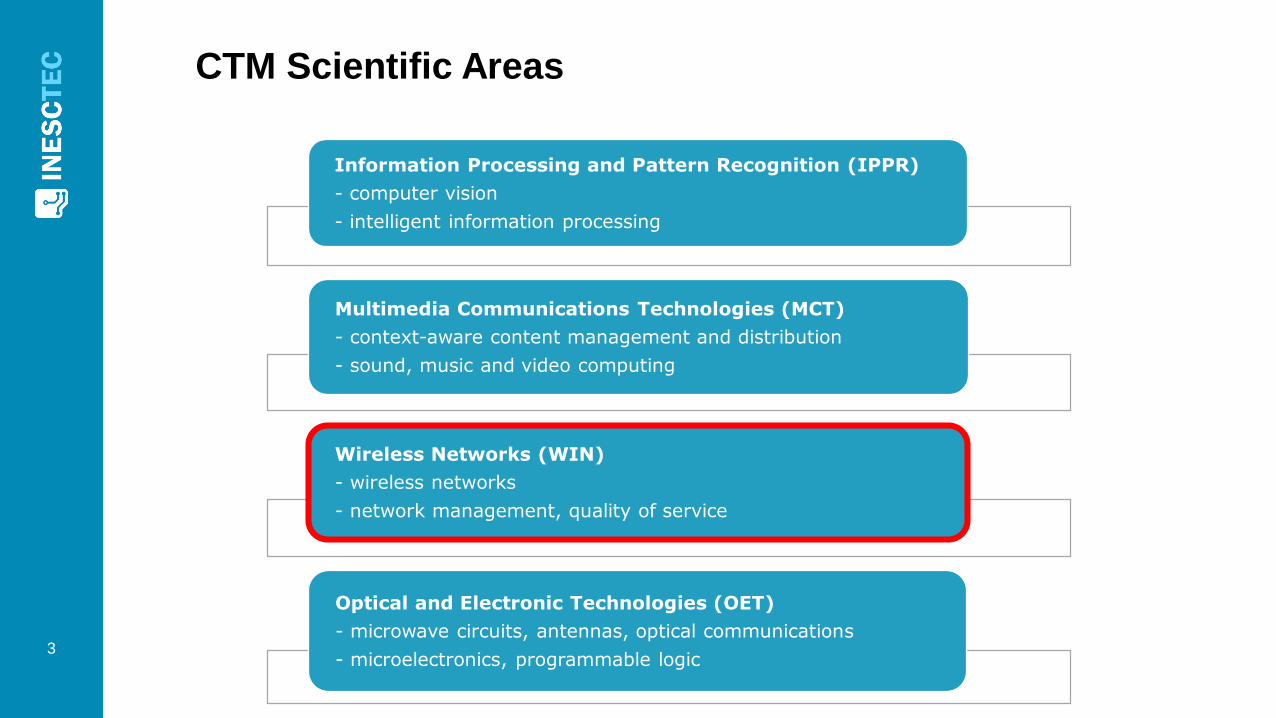
CTM Scientific Areas
3
Information Processing and Pattern Recognition (IPPR)
- computer vision
- intelligent information processing
Multimedia Communications Technologies (MCT)
- context-aware content management and distribution
- sound, music and video computing
Wireless Networks (WIN)
- wireless networks
- network management, quality of service
Optical and Electronic Technologies (OET)
- microwave circuits, antennas, optical communications
- microelectronics, programmable logic

WIRELESS NETWORKS
4
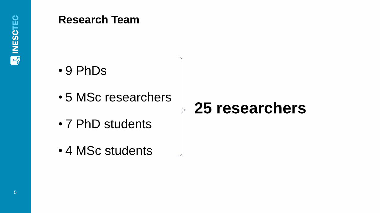
Research Team
5
• 9 PhDs
• 5 MSc researchers
• 7 PhD students
• 4 MSc students
25 researchers
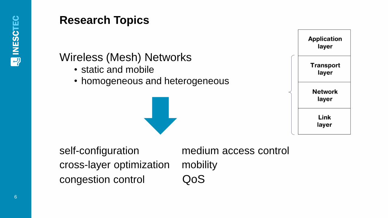
Research Topics
6
Wireless (Mesh) Networks• static and mobile• homogeneous and heterogeneous
self-configuration medium access control
cross-layer optimization mobility
congestion control QoS
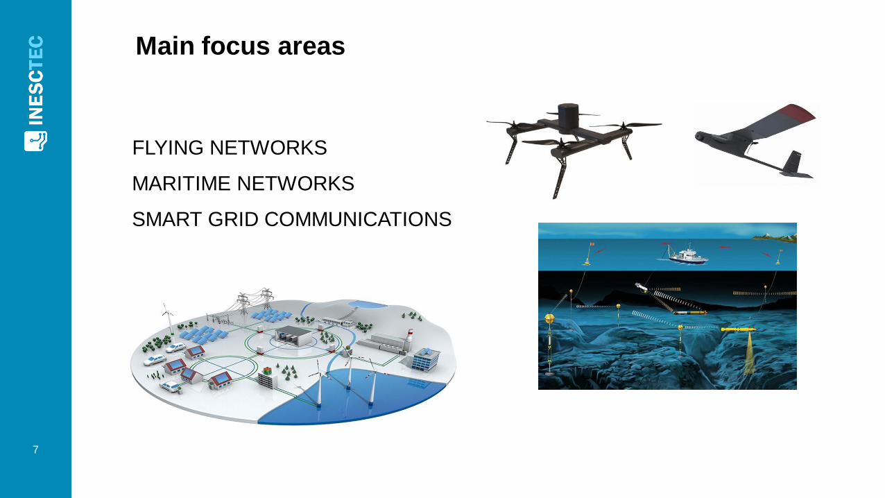
Main focus areas
7
FLYING NETWORKS
MARITIME NETWORKS
SMART GRID COMMUNICATIONS
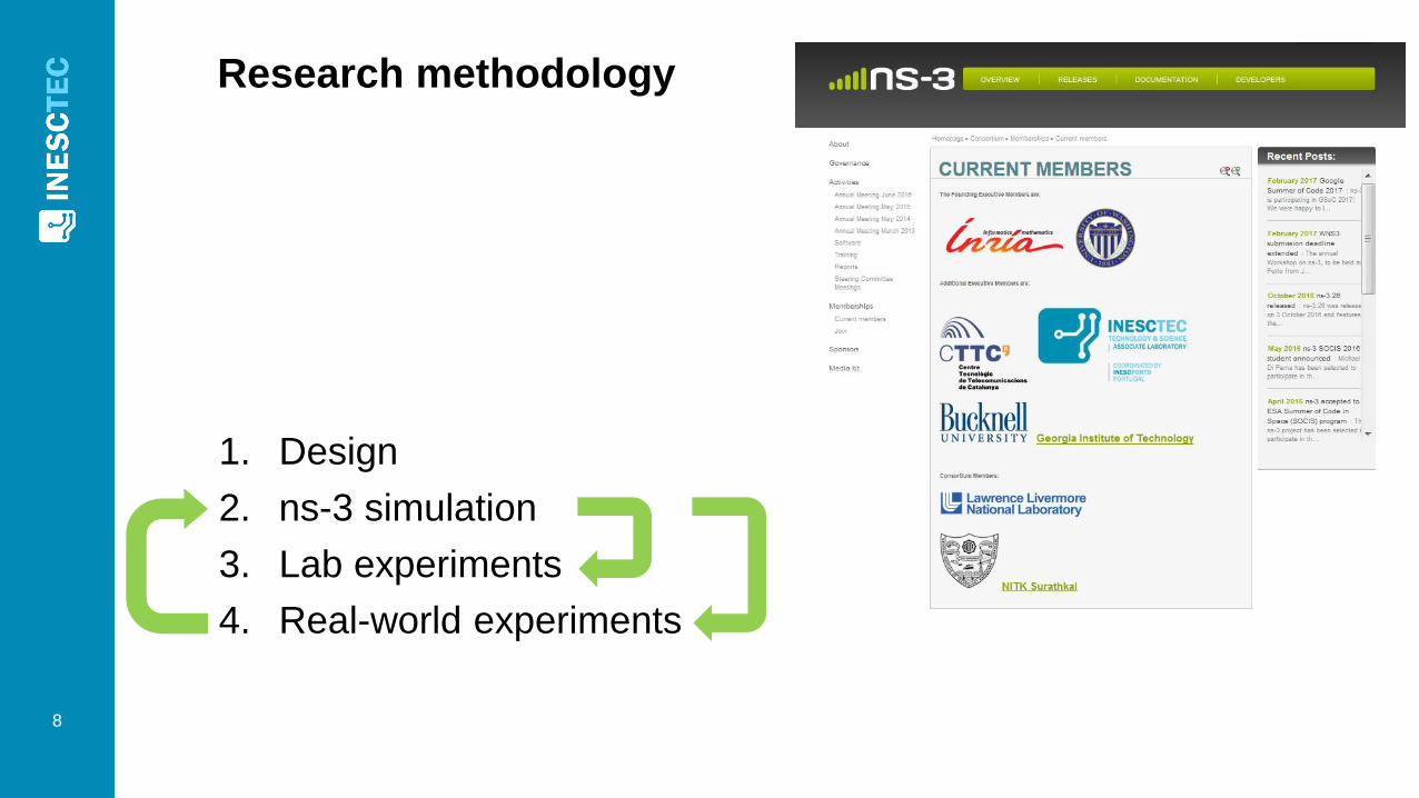
Research methodology
8
1. Design
2. ns-3 simulation
3. Lab experiments
4. Real-world experiments
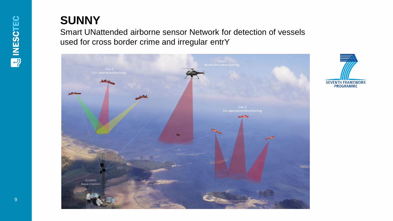
SUNNYSmart UNattended airborne sensor Network for detection of vessels
used for cross border crime and irregular entrY
9
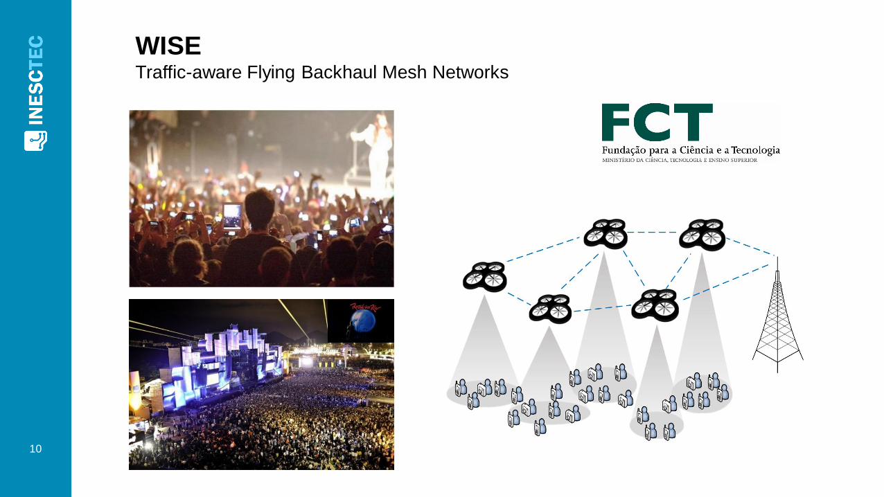
WISETraffic-aware Flying Backhaul Mesh Networks
10
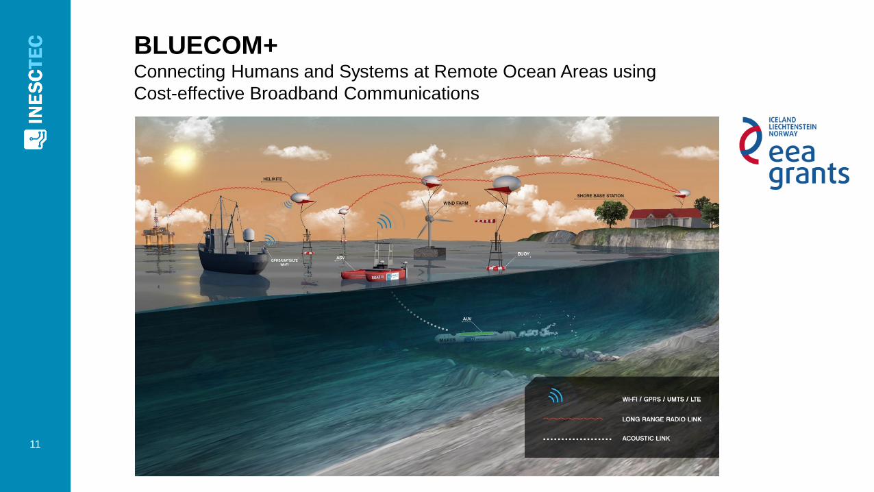
BLUECOM+Connecting Humans and Systems at Remote Ocean Areas using
Cost-effective Broadband Communications
11
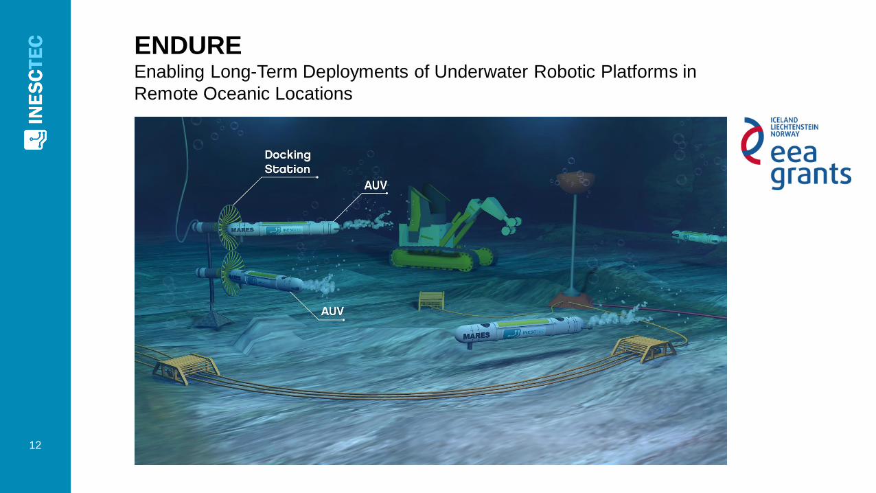
ENDUREEnabling Long-Term Deployments of Underwater Robotic Platforms in
Remote Oceanic Locations
12
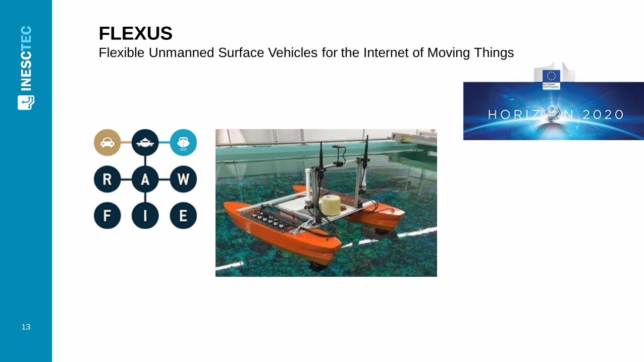
FLEXUSFlexible Unmanned Surface Vehicles for the Internet of Moving Things
13
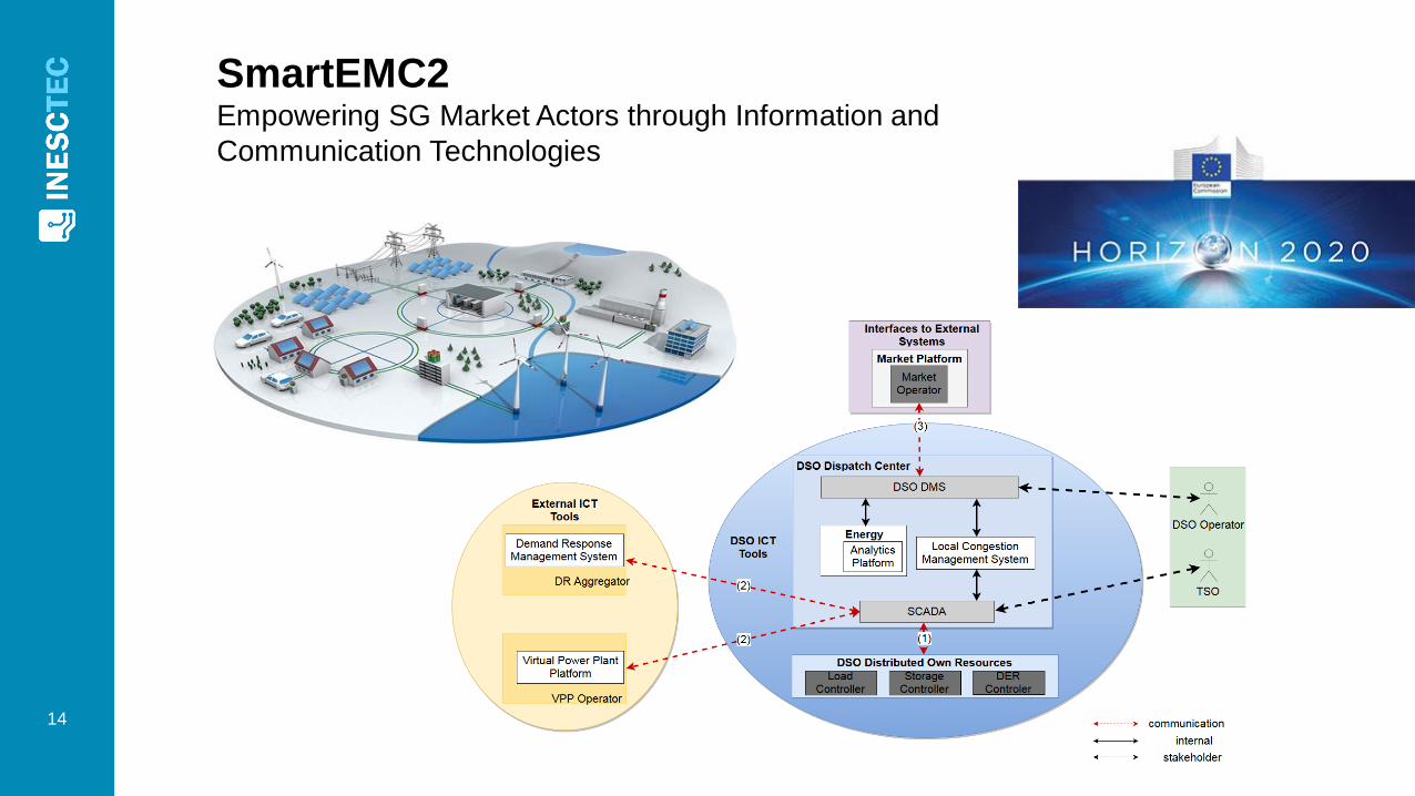
SmartEMC2Empowering SG Market Actors through Information and
Communication Technologies
14

More information
http://win.inesctec.pt
15
Evaluation of an
RPL/6LoWPAN/IEEE 802.15.4g
Solution for Smart Metering in
an Industrial Environment
Jaime Dias, Filipe Ribeiro, Rui Campos, Manuel Ricardo,
Luís Martins, Fernando Gomes, António Carrapatoso
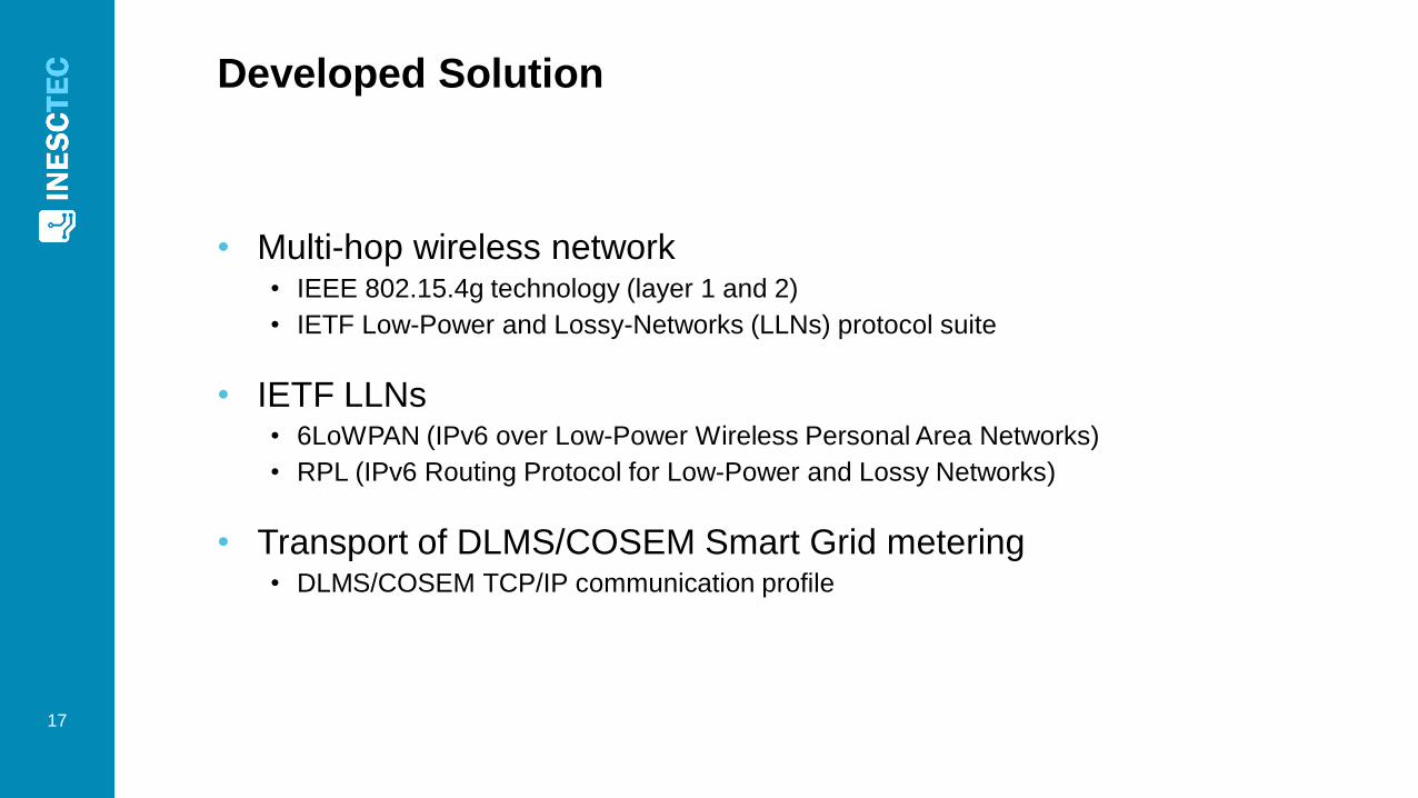
Developed Solution
• Multi-hop wireless network • IEEE 802.15.4g technology (layer 1 and 2)
• IETF Low-Power and Lossy-Networks (LLNs) protocol suite
• IETF LLNs• 6LoWPAN (IPv6 over Low-Power Wireless Personal Area Networks)
• RPL (IPv6 Routing Protocol for Low-Power and Lossy Networks)
• Transport of DLMS/COSEM Smart Grid metering• DLMS/COSEM TCP/IP communication profile
17
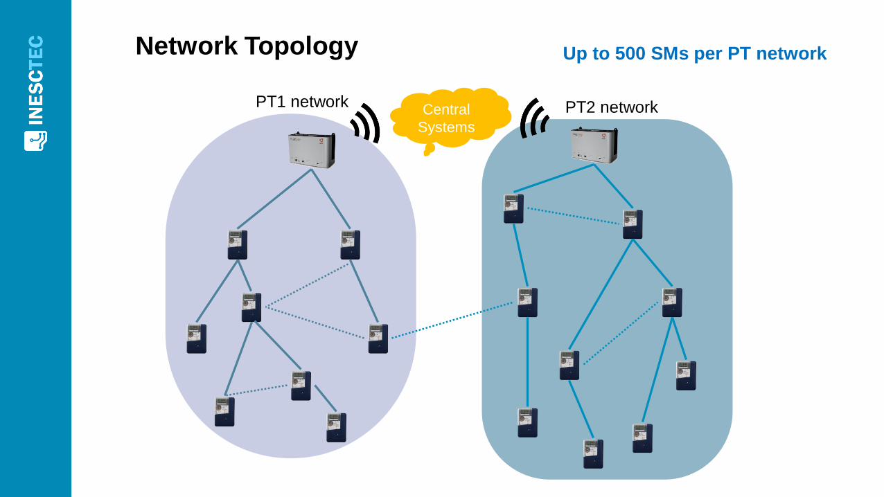
Network Topology
PT1 networkCentral
Systems
PT2 network
Up to 500 SMs per PT network
19
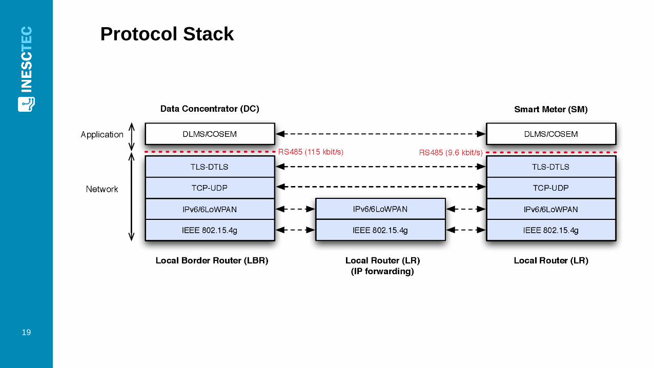
Protocol Stack
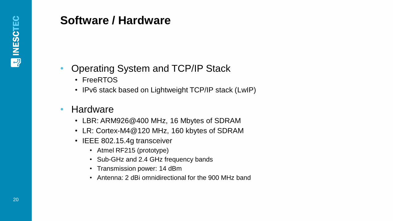
Software / Hardware
• Operating System and TCP/IP Stack• FreeRTOS
• IPv6 stack based on Lightweight TCP/IP stack (LwIP)
• Hardware• LBR: ARM926@400 MHz, 16 Mbytes of SDRAM
• LR: Cortex-M4@120 MHz, 160 kbytes of SDRAM
• IEEE 802.15.4g transceiver
• Atmel RF215 (prototype)
• Sub-GHz and 2.4 GHz frequency bands
• Transmission power: 14 dBm
• Antenna: 2 dBi omnidirectional for the 900 MHz band
20
21
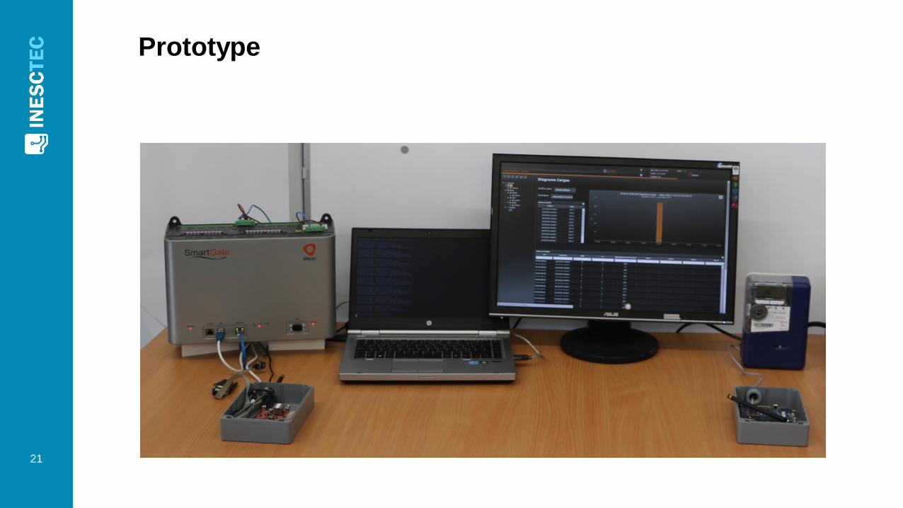
Prototype
22
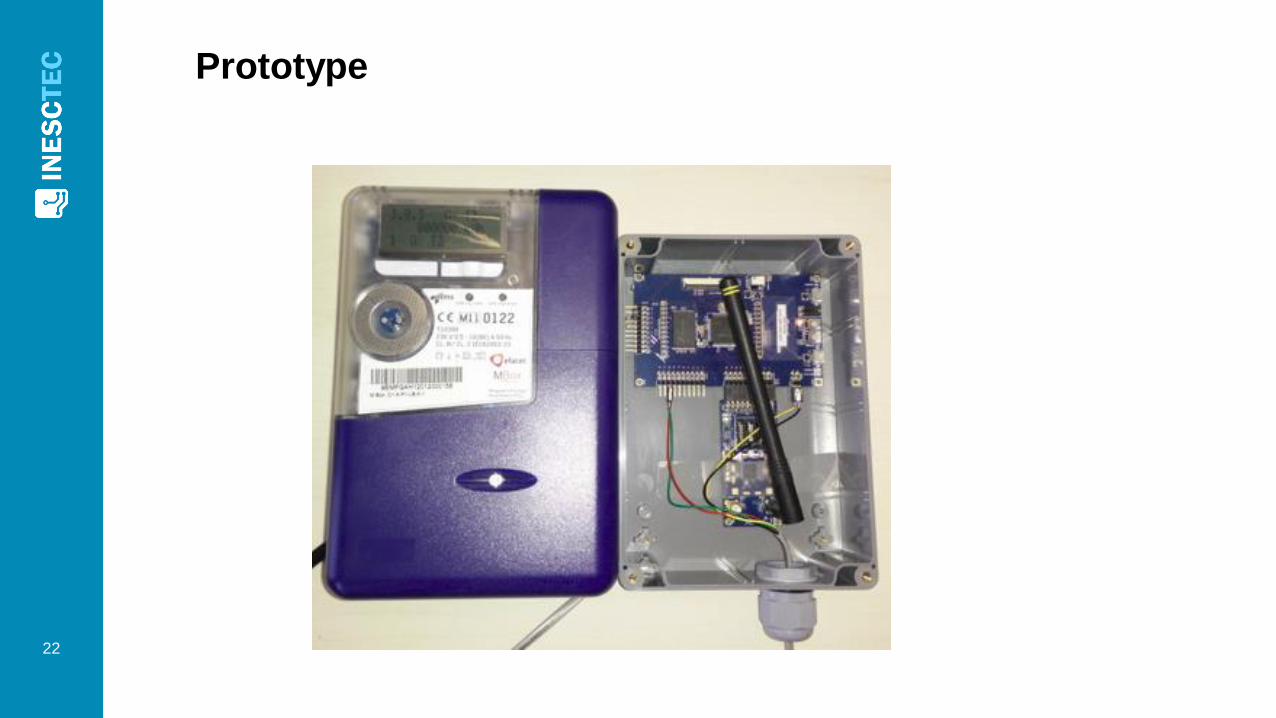
Prototype
RPL
Storing
vs.
Non-storing modes
23

Storing Mode
PT1 NetworkCentral
Systems
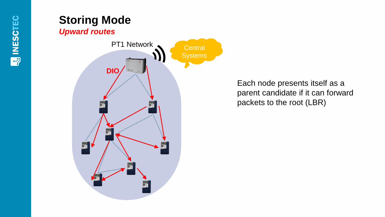
Storing Mode Upward routes
PT1 NetworkCentral
Systems
DIO
Each node presents itself as a
parent candidate if it can forward
packets to the root (LBR)
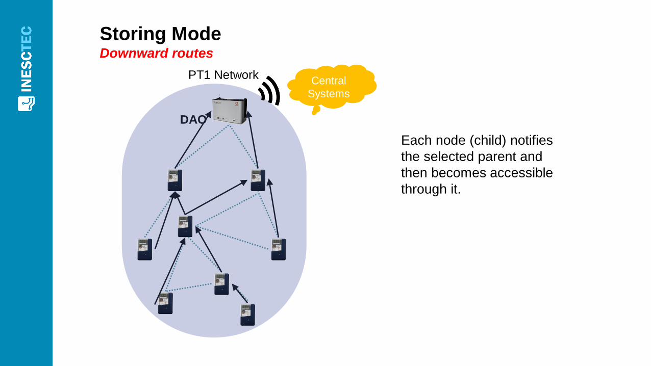
Storing ModeDownward routes
PT1 NetworkCentral
Systems
DAO
Each node (child) notifies
the selected parent and
then becomes accessible
through it.
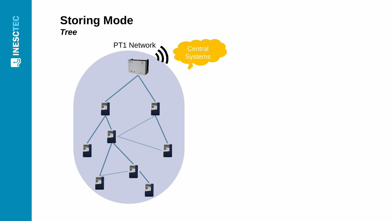
Storing ModeTree
PT1 NetworkCentral
Systems

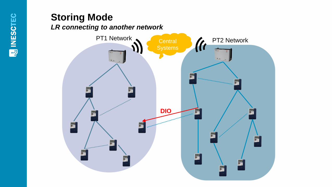
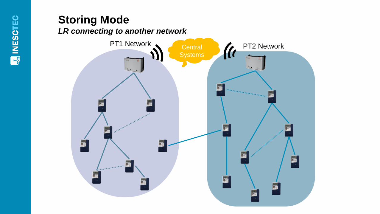
Storing ModeLR connecting to another network
PT1 NetworkCentral
Systems
PT2 Network

Storing ModeLR connecting to another network
PT1 NetworkCentral
Systems
PT2 Network

Storing ModeLR connecting to another network
PT1 NetworkCentral
Systems
PT2 Network
DIS
Storing ModeLR connecting to another network
PT1 NetworkCentral
Systems
PT2 Network
DIO

Storing ModeLR connecting to another network
PT1 NetworkCentral
Systems
PT2 Network
DAO
Storing ModeLR connecting to another network
PT1 NetworkCentral
Systems
PT2 Network
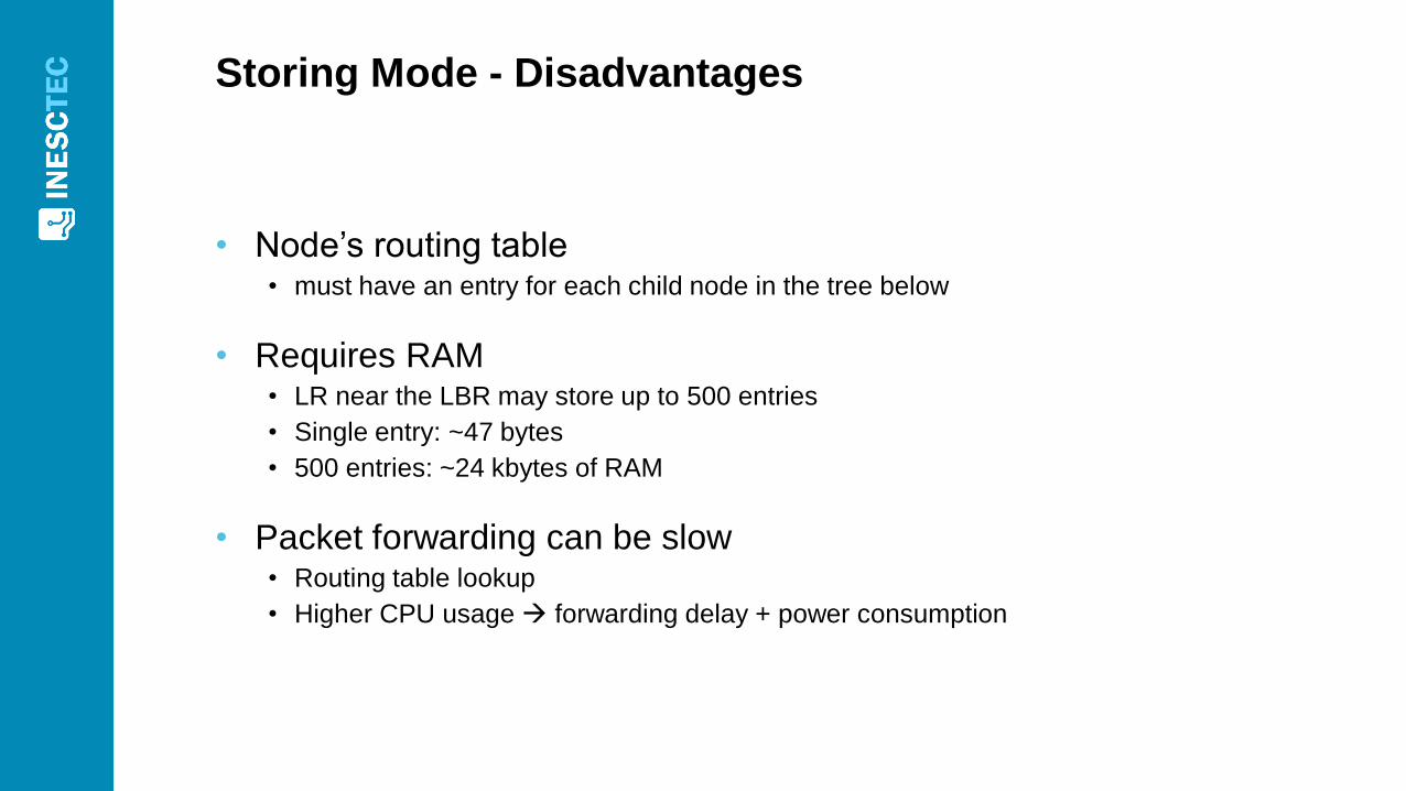
Storing Mode - Disadvantages
• Node’s routing table • must have an entry for each child node in the tree below
• Requires RAM• LR near the LBR may store up to 500 entries
• Single entry: ~47 bytes
• 500 entries: ~24 kbytes of RAM
• Packet forwarding can be slow• Routing table lookup
• Higher CPU usage forwarding delay + power consumption
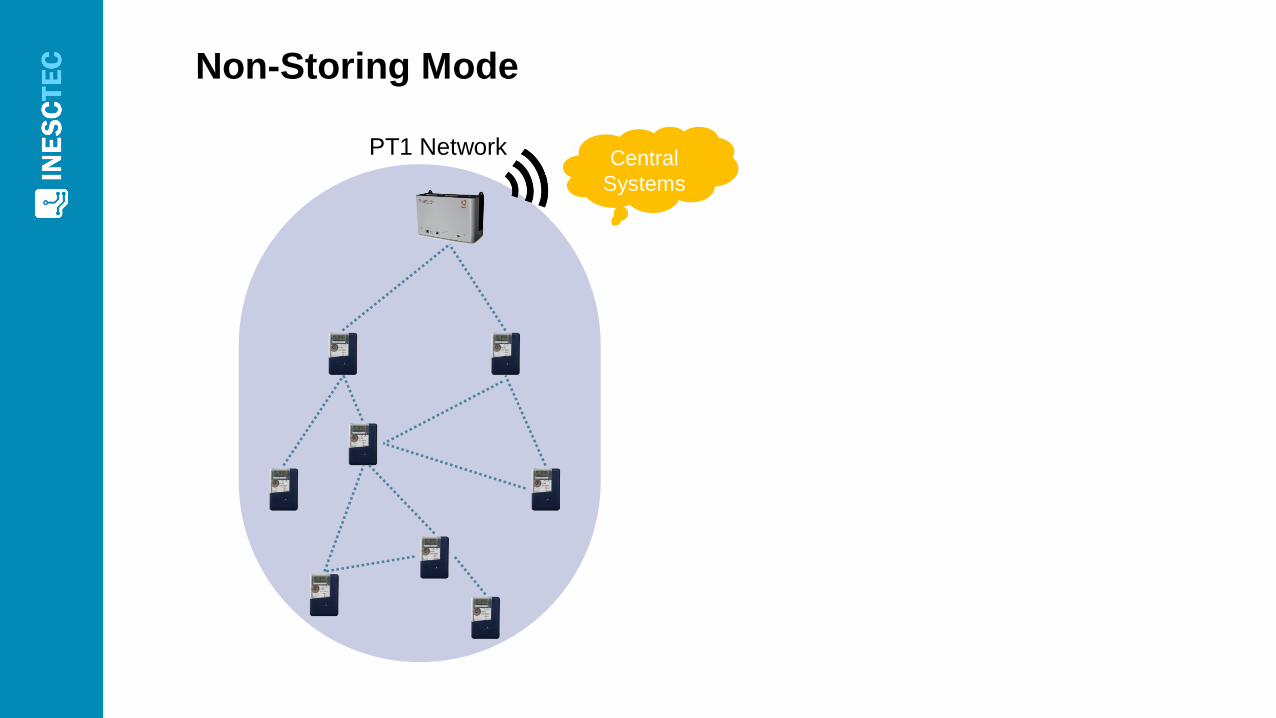
Non-Storing Mode
PT1 NetworkCentral
Systems
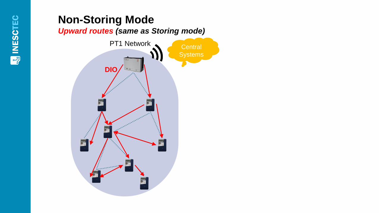
Non-Storing ModeUpward routes (same as Storing mode)
PT1 NetworkCentral
Systems
DIO
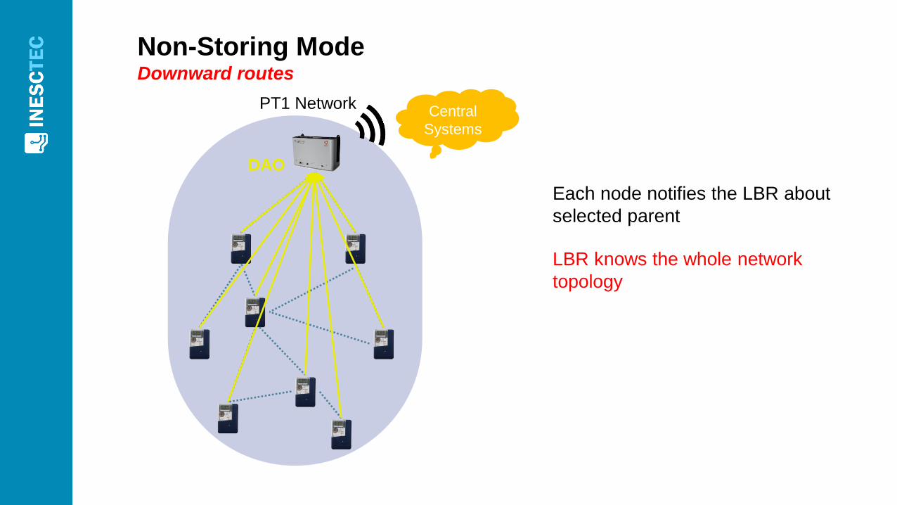
Non-Storing ModeDownward routes
PT1 NetworkCentral
Systems
DAO
Each node notifies the LBR about
selected parent
LBR knows the whole network
topology
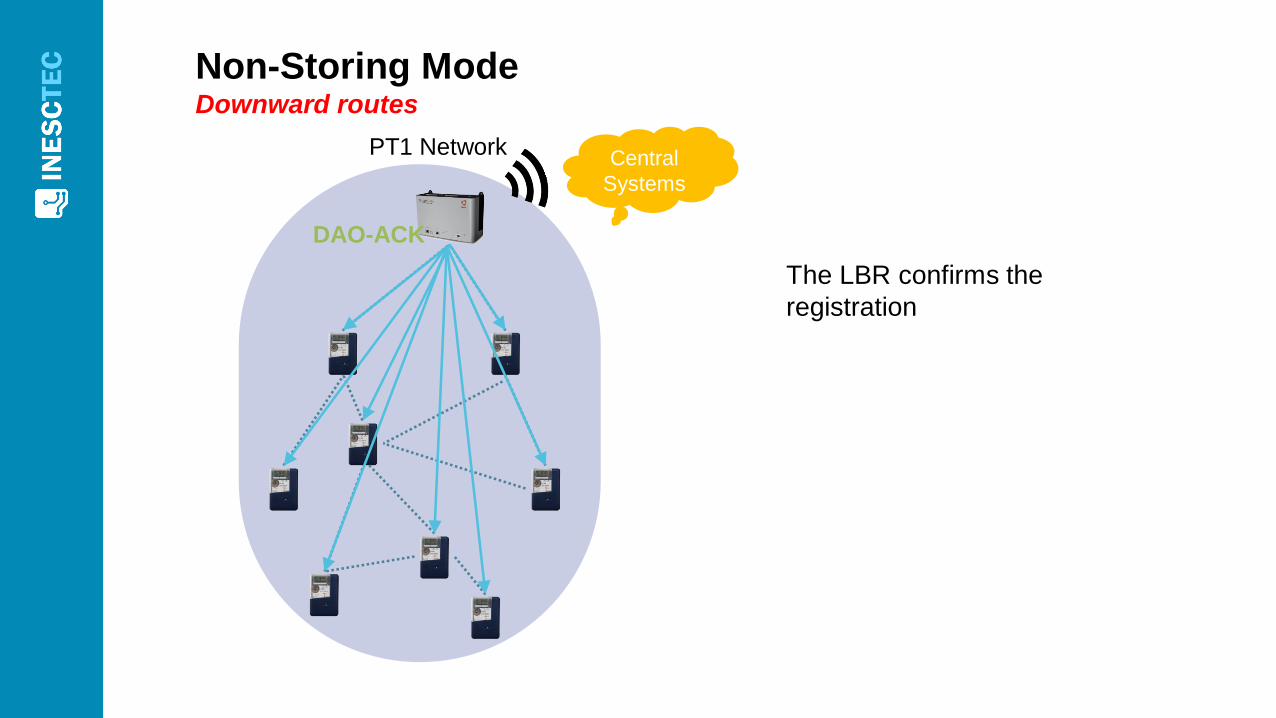
Non-Storing ModeDownward routes
PT1 NetworkCentral
Systems
DAO-ACK
The LBR confirms the
registration
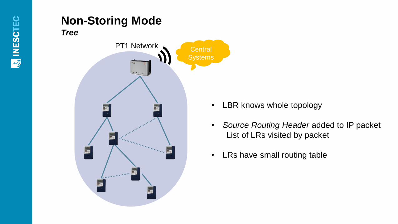
Non-Storing ModeTree
PT1 NetworkCentral
Systems
• LBR knows whole topology
• Source Routing Header added to IP packet
List of LRs visited by packet
• LRs have small routing table
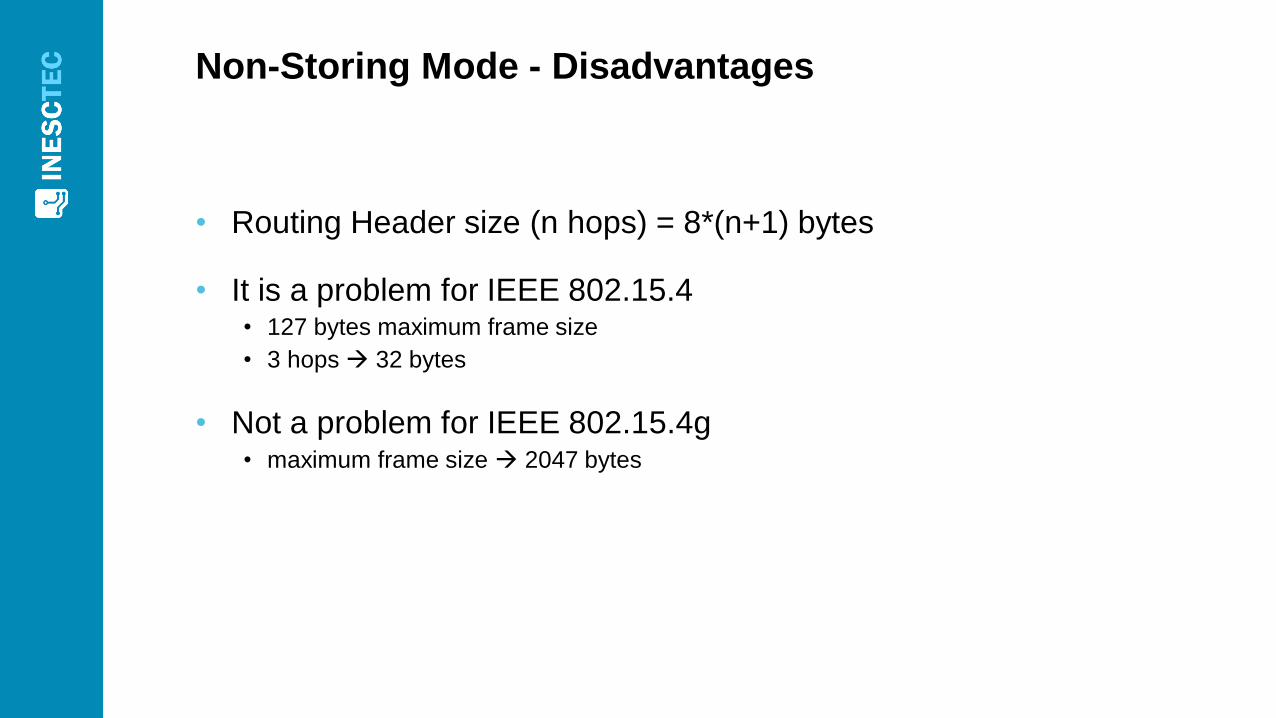
Non-Storing Mode - Disadvantages
• Routing Header size (n hops) = 8*(n+1) bytes
• It is a problem for IEEE 802.15.4 • 127 bytes maximum frame size
• 3 hops 32 bytes
• Not a problem for IEEE 802.15.4g• maximum frame size 2047 bytes
Non-Storing Mode - Disadvantages
• Traffic between 2 LRs passes through root node• Unless LRs have same parent
• Unlikely scenario in Smart Metering
• Non-storing mode was used

Experimental tests
42
Testbed
• 2 PT(LBR), 10 SM (LR)
• Only 1 LBR used at time
• Security disabled DLMS over TCP or UDP
• Transceivers• Channel 7 @ 915 MHz band, bandwidth of 2 MHz
• O-QPSK with 250 kbit/s data rate
• TX power: 14 dBm
• Sensitivity: -102 dBm
43
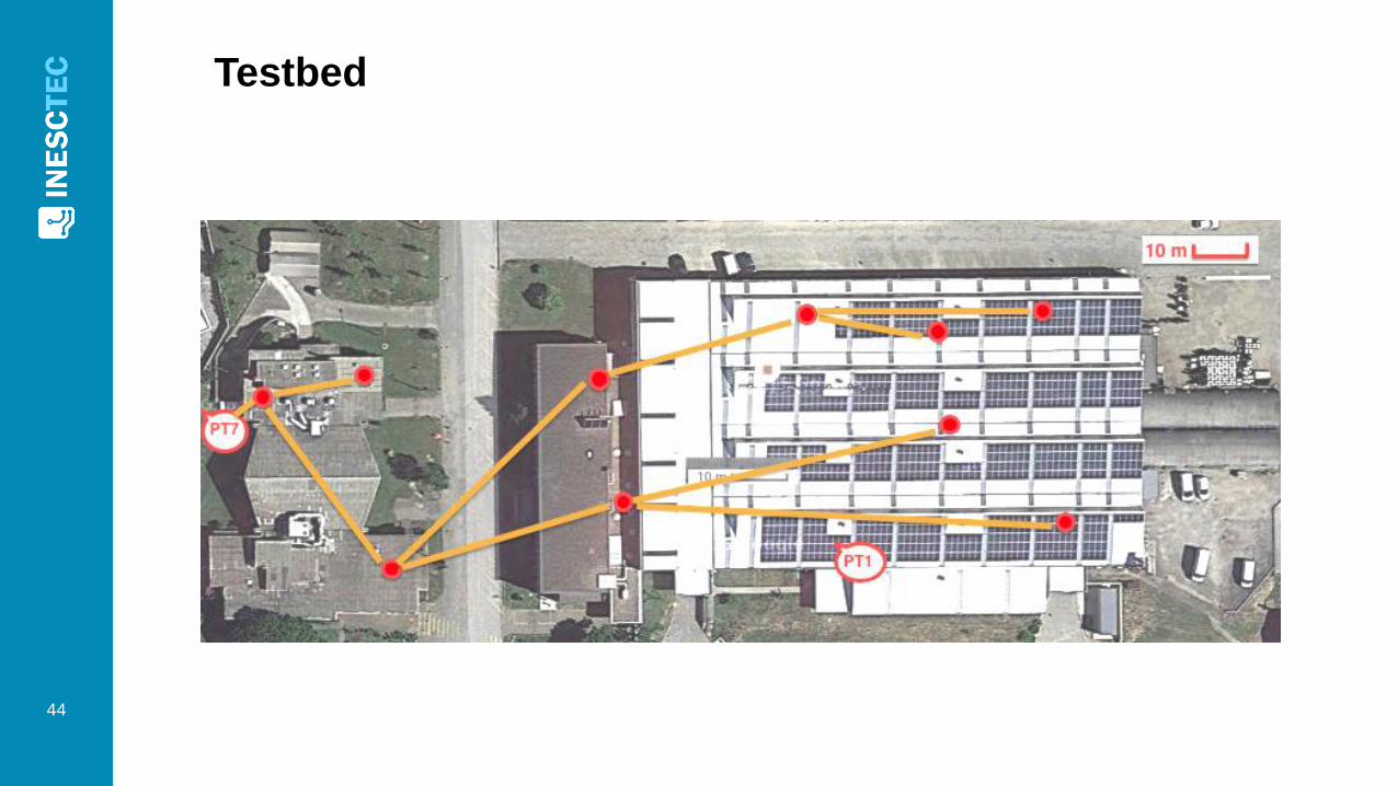
Testbed
44
Tests
• 20 days of experimental testing
• Three stages
1. Ping tests to LRs during 11.5 days
2. DLMS/COSEM application tests over TCP and UDP during 7 days
3. IEEE 802.15.4 packet sniffing near LBR during 28 hours
45
Stage 1: Ping to LRs
• Ping tool used to measure performance at the IP layer
• Duration: 11.5 days
• Procedure• Continuous rounds of pings to all LRs
• 100 consecutive requests to each LR in each round
46
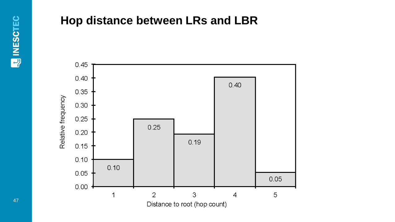
Hop distance between LRs and LBR
47
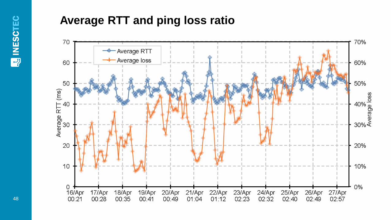
Average RTT and ping loss ratio
48
Average RTT and ping loss ratio
• Average RTT near 50 ms almost all the time
• Average ping loss ratio between 10% and 60%• Ping loss ratio (echo request + echo reply)
is higher than packet loss ratio (one way)
• It is a Lossy Network!
49
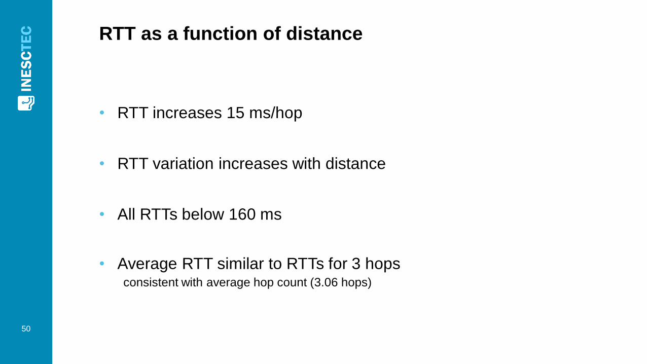
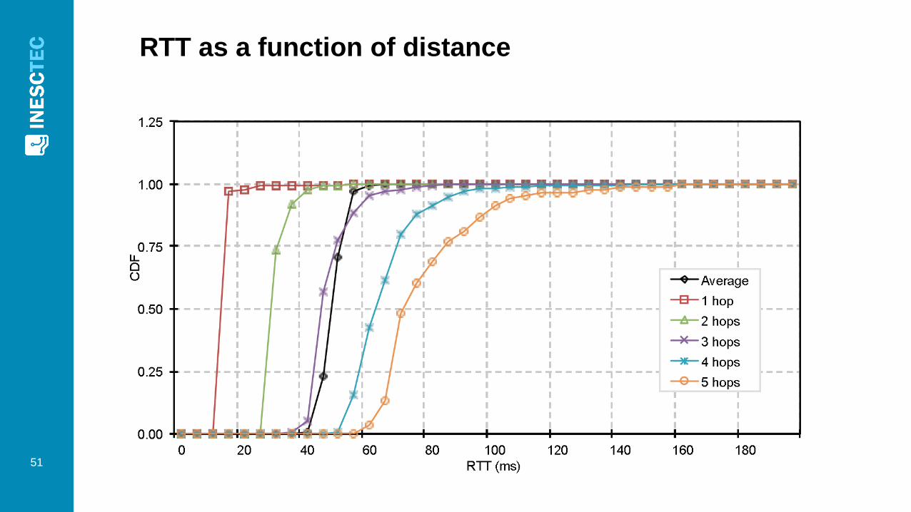
RTT as a function of distance
• RTT increases 15 ms/hop
• RTT variation increases with distance
• All RTTs below 160 ms
• Average RTT similar to RTTs for 3 hopsconsistent with average hop count (3.06 hops)
50
RTT as a function of distance
51
Stage 2: DLMS/COSEM over TCP and UDP
• DLMS/COSEM application used to measure
performance of DLMS protocol over TCP and UDP
• Duration: 7 days
• From DLMS/COSEM client (DC) to servers (SMs)
• Measurements at the application layer• DLMS session duration
• DLMS session failure ratio
52
Stage 2: DLMS/COSEM over TCP and UDP
• 20 000 DLMS rounds
• DLMS round: 3 consecutive DLMS sessions to each LR
• Transport switched between TCP and UDP every 30 minutes
• Timeout and maximum number of DLMS retransmissions• For UDP: timeout of 5 s and a 8 retransmissions
• For TCP: timeout of 60 s and 1 retransmission
• DLMS messages length• Requests: 64 bytes
• Responses: 128 bytes
• DLMS session duration includes UARTs delays• UART@LBR: 115.2 kbit/s
• UART@LR: 9.6 kbit/s
• 173 ms to Tx messages through UARTs
53
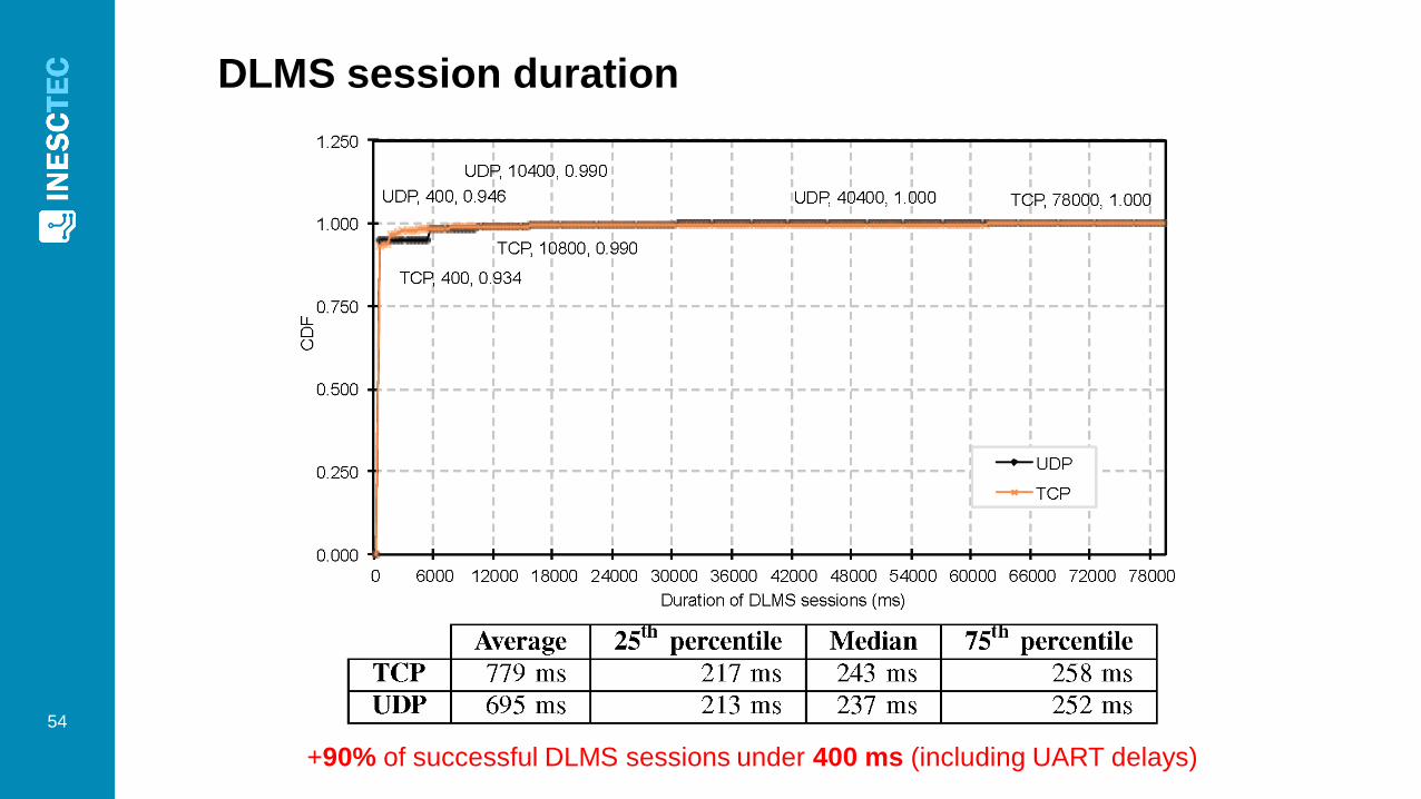
DLMS session duration
54
+90% of successful DLMS sessions under 400 ms (including UART delays)
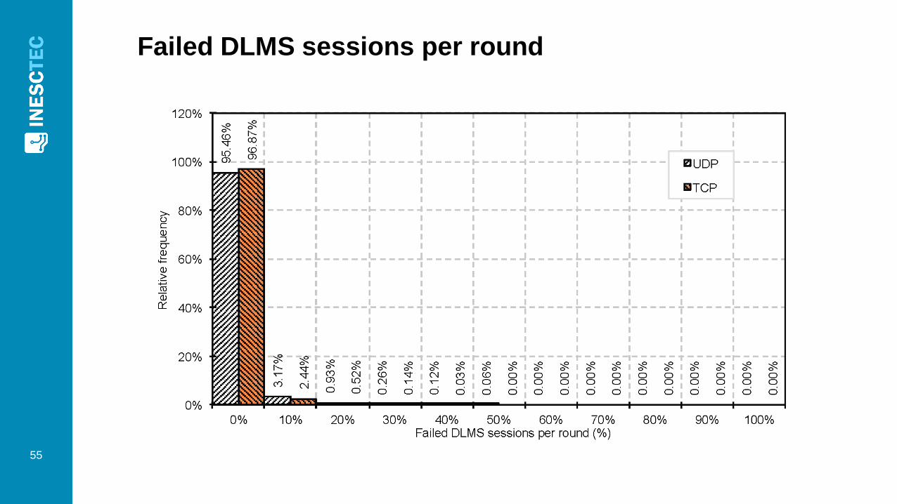
Failed DLMS sessions per round
55
Stage 3: IEEE 802.15.4 packet sniffing
• Used to measure IP control traffic in the medium near the LBR
• Duration: 28 hours
• IEEE 802.15.4 packet sniffer near LBR
• Procedure• DLMS rounds made to all LRs
• As in Stage 2
56
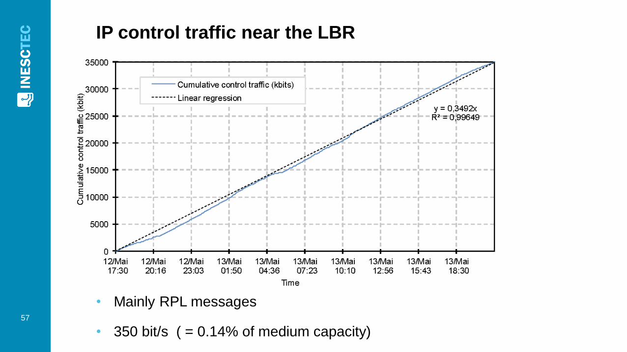
IP control traffic near the LBR
57
• Mainly RPL messages
• 350 bit/s ( = 0.14% of medium capacity)
Conclusions
• IP packet loss ratio is high
• RTT increased 15 ms/hop
• Repetition helps overcoming packet loss
• Failed DLMS sessions/round• 0.25% for TCP
• 0.47% for UDP
• +90% of DLMS sessions completed before 400 ms
58

THE END
59