industrial training presentation on regional workshop of utc(uttrakhand transport corporation) by...
TRANSCRIPT

INDUSTRIAL TRAINING PRESENTATION ON REGIONAL WORKSHOP OF UTC(UTTRAKHAND TRANSPORT CORPORATION)
BY :VISHAL BISHAWAKARMA

ABOUT UTTARAKHAND MANDALIYA KARYALIYA, KATHGODAM
WORKSHOP FOR UTTARAKHND ROADWAYS BUSES IS SITUATED IN KATHGODAM AND IS BEST KNOWN AS UTTARAKHAND MANDALIYA KARYALIYA. MAINTENANCE WORK OF ROADWAYS PASSANGER VEHICLE IS DONE HERE WHICH INCLUDES SPARE REPLACEMENT ,LUBRICATION , INSPECTION ,REPAIR,TESTING ETC OF DIFFERENT PARTS OF VEHICLES. MOST OF JOB IS MANUALLY IN DIFFERENT SECTION PROVIDED FOR MAINTENANCE AND REPAIR OF DIFFERENT PARTS OF AUTOMOBILE.

SERVICES
The constructed parts are supplied to the following Roadways Depots as per the need.• Ranikhet Depot• Kashipur Depot• Bhowali Depot • Almora Depot • Haldwani Depot • Ramnagar Depot
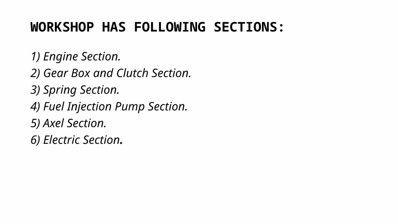
WORKSHOP HAS FOLLOWING SECTIONS:
1) Engine Section.2) Gear Box and Clutch Section.3) Spring Section.4) Fuel Injection Pump Section.5) Axel Section.6) Electric Section.

ENGINE SECTION

Diesel engine of buses used in roadways buses is manufactured of tata and Ashok Leyland. Both engine are 6 cyinder turbo chaged intercooled Diesel engine.Engines of the following buses are repaired in the workshop• TATA- 1312• TATA- 1520• TATA- 1210• LEYLAND

1.
SPECIFICATIONS OF ENGINE-:
MODEL – T.C. 1312 (TATA).
2. NUMBER OF CYLINDER – 6.
3. BORE SIZE – 102 mm.
4. FUEL USED- DIESEL.
5. FIRING ORDER- 1-5-3-6-2-4
6. INJECTION PRESSURE- 175-180.
7. AVERAGE – 5-6 km/lt.

COMPARISON B/W TATA AND ASHOK LEYLAND DIESEL ENGINE
SERIAL NO. PARAMETER TATA ENGINE ASHOK LEYLAND ENGINE
1. ENGINE TYPE DIESEL ENGINE DIESEL ENGINE
2. NO. OF CYLINDER 6 6
3. CYLINDER ARRANGEMENT INLINE INLINE
4. LUBRICATION TYPE PRESSURE LUBRICATION BY ROTARY PUMP
PRESSURE LUBRICATION BY ROTARY PUMP
5. POWER OUTPUT 125 HP 135HP
6. TURBOCHARGER YES YES
7. OIL PUMP ROTARY ROTARY
8. COMBUSTION CHAMBER DIRECT INJECTION(HEMISPHERIC DISHED PISTON)
DIRECT INJECTION(HEMISPHERIC DISHED PISTON)

PARTS OF ENGINE:-
There are following parts of an Engine-:
1. Cylindrical Head.
2. Oil Pump.
3. Cylinder Block.
4. Piston.
5. Crank Shaft.
6. Cam Shaft.
7. Cooling Fan.
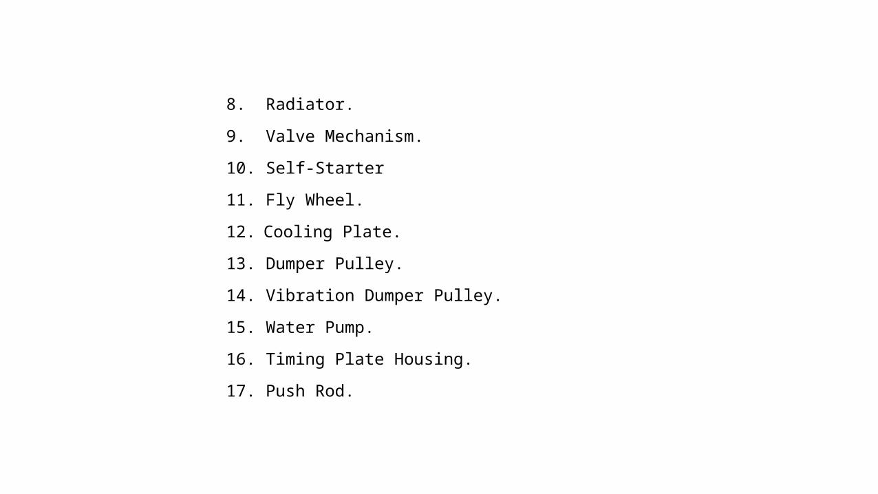
8. Radiator.
9. Valve Mechanism.
10. Self-Starter
11. Fly Wheel.
12. Cooling Plate.
13. Dumper Pulley.
14. Vibration Dumper Pulley.
15. Water Pump.
16. Timing Plate Housing.
17. Push Rod.

18. Diesel Filter.
19. Tappet.
20. Gudgeon Pin.
21. Alternator.
22. Turbo Charger.

LUBRICATION SYSTEM
1) OIL PUMP
2)OIL SEALS
3)ENGINE OIL DIP STICK
4)OIL FILLER CAP ON TOP SECOND CYLINDER
5)OIL FILTER
6)OIL PASSAGES
7)OIL PAN

ACCESSORIES DRIVEN BY ENGINETHOSE DRIVEN BY TIMING GEARS
1. CAMSHAFT
2. OIL PUMP
THOSE DRIVEN THROUGH BELTS
3. AIR COMRESSOR
4. FUEL PUMP
5. RADIATOR FAN

WAY OF SERVICING
1. The whole engine is dismantled manually and the oil is removed from sump
2. Main shaft bearing, sliding contact bearing , plastic passages for oil is replaced by new one .
3. Cleaning of engine block and other parts .
4. Piston rings which is of three types pressure rings , oil rings , oil ring and top ring also replaced by new one.
5. After replacing all worn out parts the engine is assembled and tested by employing fuel pump and overflow pipe to the tank which is fuel filled.

Fuel Pump Section

Fuel Pump used
In Diesel Engine F.I. Pump is used for carrying the in correct amount time, high pressure and reaches it to injector in it the injection pressure is 7 to 30 M Pa and is Bosch
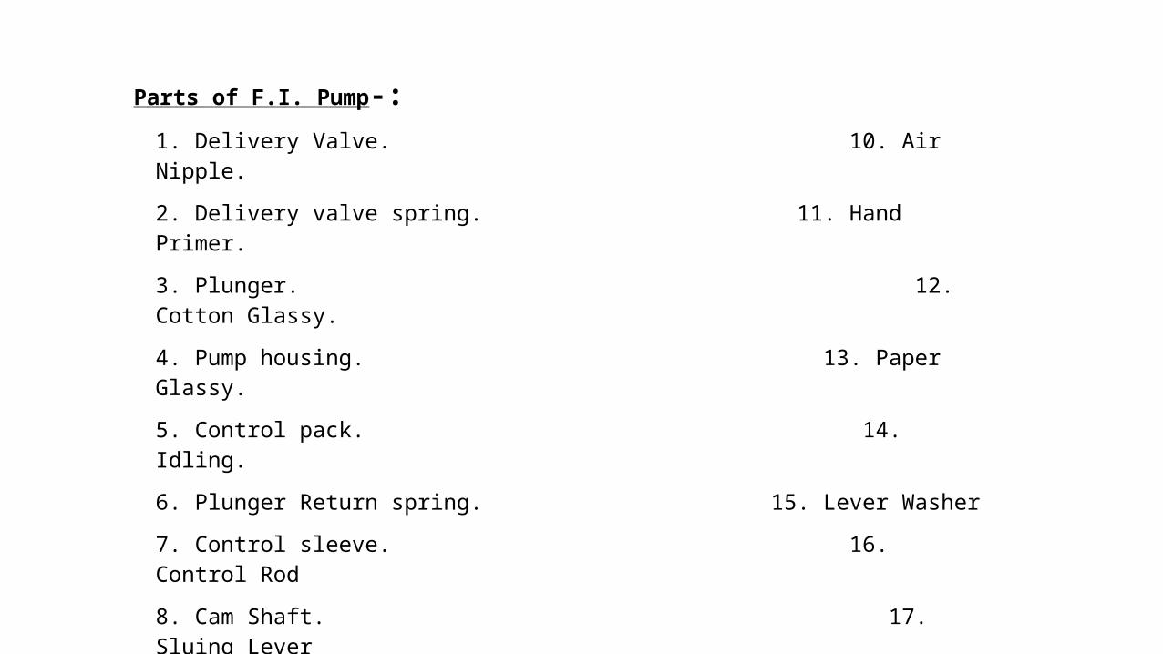
Parts of F.I. Pump-:
1. Delivery Valve. 10. Air Nipple.
2. Delivery valve spring. 11. Hand Primer.
3. Plunger. 12. Cotton Glassy.
4. Pump housing. 13. Paper Glassy.
5. Control pack. 14. Idling.
6. Plunger Return spring. 15. Lever Washer
7. Control sleeve. 16. Control Rod
8. Cam Shaft. 17. Sluing Lever
9. Feed Pump. 18. Fly Weight

SPECIFICATION OF F.I. PUMP-:
Model -Bosh Type F.I. Pump
Injection Pressure - 7 to 30 M Pa.
CAM Sequence - 1-5-3-6-2-4.
Direction of Rotation -Clock Wise.

WORKING PRINCIPLE-:Fuel by suck fuel pump from the tank at low pressure with the help of filter. Fuel is supplied to unit injector where its pressure is increased. And the high pressure fuel is then supplied to the engine cylinders at appropriate time. Any extra fuel goes again to tank through relief valve.

TESTING OF FUEL PUMPTesting of fuel pump is done on fuel pump is done fuel pump test bench which
• Measuring each cylinder delivery at any speed.• Checking of each cylinder injection timing with static .• Check the pneumatic control performance.

TEST BENCH
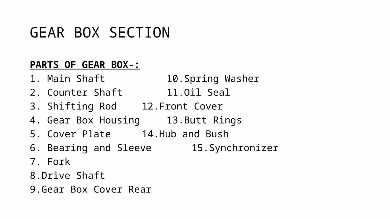
GEAR BOX SECTION
PARTS OF GEAR BOX-: 1. Main Shaft 10.Spring Washer2. Counter Shaft 11.Oil Seal3. Shifting Rod 12.Front Cover4. Gear Box Housing 13.Butt Rings5. Cover Plate 14.Hub and Bush6. Bearing and Sleeve 15.Synchronizer7. Fork 8.Drive Shaft9.Gear Box Cover Rear


ASSEMBLY-:
Counter Shaft adjusts in Gear Box which is made up of Cast Iron by Casting. There are Five Gears in counter shaft. Main shaft acts as a base purpose shaft. The main shaft is assembled in which there are 6 helical gears. There are 5 forward and 1 reverse gear. In these sleeve fork fits after the shifting rod.

Number of Teeth in each Gear-:
In Main Shaft-:
1. First Gear - 39
2. Second Gear – 32
3. Third Gear – 25 or 26
4. Fourth Gear – 19 or 20
5. Fifth Gear – 17
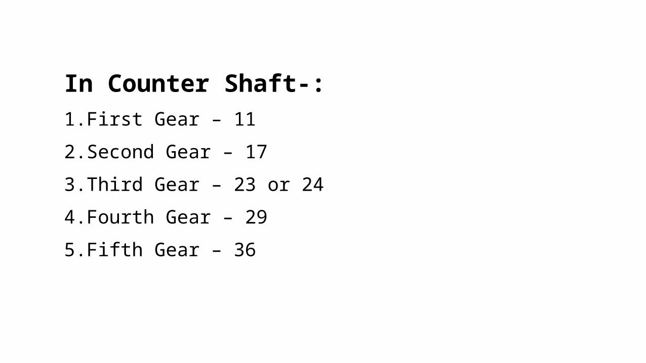
In Counter Shaft-:
1. First Gear – 11
2. Second Gear – 17
3. Third Gear – 23 or 24
4. Fourth Gear – 29
5. Fifth Gear – 36

THANK YOU