industrial energy managementenergy... · type of steam boilers kettle boiler flue tube boiler fire...
TRANSCRIPT

1Industrial Energy Management
Industrial energy management
Fossil fuel power plants

2Industrial Energy Management
Layout of power plant

3Industrial Energy Management
Coal is primary fuel source (~40%) for electricity production
A physically heterogeneous, “combustible” sedimentary rock.
Inorganic mineral + Organic part (mainly C, O and H, with little S and N)
It is formed from decay and sedimentation of vegetal matter (Coalification)
Moisture
Volatile Matter : Compounds released in the gas phase, e.g. CH4, released after heating
Dry Carbon : Compounds that remains after heating but that can be burned
Fly ashes : Inorganic matter that are left after the combustion
Coal

4Industrial Energy Management
Coalification : Peat ->Lignite ->Subbituminous -> Bituminous ->AnthraciteReserves: USA (27%), Russia (18%), China (13%), Australia (9%), India (7%, high rank), Germany (5%, low rank) Reserve to Prod: China (40y), USA and Russia (>200 year)
Rank of coal
Moist mineral-free basis
10000 Btu/lb ~ 23,2 MJ/kg

5Industrial Energy Management
• Fuel composition
C H S O N Volatile Water Ashe
s
LHV
(MJ/kg
)
Heavy fuel oil 85 11 1-5 - 1 - - - 41.0
Light fuel oil 86 13 <0.1 - 0.005-
0.05
42.7
Diesel 86 14 <0.005 42.7
Gasoline 85 15 <0.002 43.5
Anthracite 90-
95
<4 1 2 1 10 5 3-10 29
Bituminous 76-
90
5-7 1 5-10 1 10-30 5-10 3-10 18-29
Submituminous 72-
76
5 1 15-25 1 30-40 10-30 3-15 8-25
Lignite 65-
72
4-7 0.2-1 15-30 0.5-1 40-48 30-70 3-15 5-20
Wood 47-
53
5-7 0-0.3 42-46 0-0.7 60-90 10-20 0-4 17-21
Dry-ash-free composition

6Industrial Energy Management
• On the board :
Coal versus gas
kg CO2/ kWh of
thermal power
Coal (anthracite) 0.351
Coal (bituminous) 0.316
Coal (lignite) 0.331
Coal
(subbituminous) 0.329
Diesel fuel and
heating oil 0.248
Gasoline 0.241
Propane 0.213
Natural gas 0.180
Germany: ~0,67 kg CO2
per kWh electricity
Source : US Energy Administration
Enthalpies of
formation at 25°C
and 1 atm
(kJ/kmol)
C(s) 0
O2(g) 0
CH4(g) -74,850
CO2(g) -393,520
H2O(g) -241,820
H2O(l) -285,830
7Industrial Energy Management
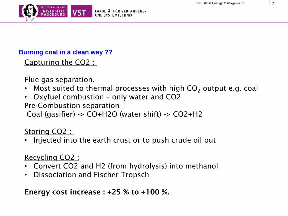
Burning coal in a clean way ??
Capturing the CO2 :
Flue gas separation.
• Most suited to thermal processes with high CO2
output e.g. coal
• Oxyfuel combustion – only water and CO2
Pre-Combustion separation
Coal (gasifier) -> CO+H2O (water shift) -> CO2+H2
Storing CO2 :
• Injected into the earth crust or to push crude oil out
Recycling CO2 :
• Convert CO2 and H2 (from hydrolysis) into methanol
• Dissociation and Fischer Tropsch
Energy cost increase : +25 % to +100 %.
8Industrial Energy Management
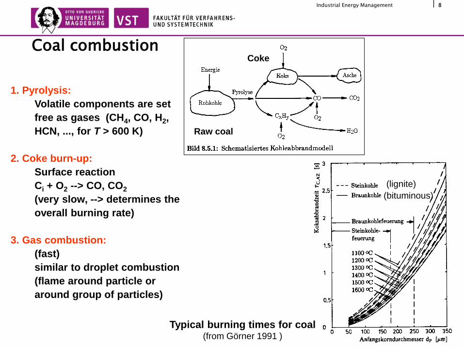
Coal combustion
1. Pyrolysis:
Volatile components are set
free as gases (CH4, CO, H2,
HCN, ..., for T > 600 K)
2. Coke burn-up:
Surface reaction
Ci + O2 --> CO, CO2
(very slow, --> determines the
overall burning rate)
3. Gas combustion:
(fast)
similar to droplet combustion
(flame around particle or
around group of particles)
Raw coal
Coke
Typical burning times for coal (from Görner 1991 )
(lignite)
(bituminous)

9Industrial Energy Management
Classification of firing
(following Reh 1976, from Görner 1991)
Bubbling Bed CirculatingPulverised Coal
FiringGrate Firing
Fluidized bed firing
Large coal particles(~5mm) / Smaller particles (1mm) / Fine particles (~50µm)

10Industrial Energy Management
Type of steam boilers
kettle boilerflue tube boiler
fire tube boiler
fire-flue- tube boilerfire-flue- tube boiler
(Holland type)
angular tube boiler steep tube boilersteep tube radiation
boiler
shell boilers
water-tuber boilers
Generating steam

11Industrial Energy Management
Fire tube boilersSource: Hoyrytys
• Generally low load <10 MW
• High inertia so can adapt load
changes
• Little maintenance and capital
investment
• P<4 MPa and no superheat :
Poor efficiency of Rankine cycle
• Mainly used for district and
industrial heating & process
steam
• Firing efficiency
Reaction chamber
12Q
Reactants RProducts P
State 1 State 2
)()( P R 25
,
25
,12
12
RP T
C
Rp
B
R
T
C
Pp
B
Pu
B
B dTTcn
ndTTc
n
nH
n
ValueHeating Lower
heat Available12 u
B
FH
q

12Industrial Energy Management
Water-tube boilers
1 feed water inlet, 2 economizer, 3 steam drum, 4 evaporator,
5 distributor, 5 ash, 7 cóal and combustion air, 8 superheater,
9 fresh steam, 10 exhaust gas, 11 recirculation pump
12 moist separator (sediment bowl)
a: natural circulation boiler b: forced circulation boiler
once-through forced flow boiler: c: Benson type, d: sulzer type
3 main heat source to water/steam heat
exchangers :
• Economiser
• Evaporator
• Superheater
With steam drum
a. Natural circulation
b. Forced circulation
All heat exch. are in series
c. Benson type
d. Sulzer type
c and d have all Heat exc. in series
13Industrial Energy Management
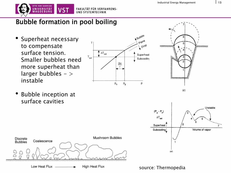
• Superheat necessary to compensate surface tension. Smaller bubbles need more superheat than larger bubbles - > instable
• Bubble inception at surface cavities
Bubble formation in pool boiling
source: Thermopedia

14Industrial Energy Management
• A : Natural convection –single phase convection
• B: Nucleate boiling – heat transfer coefficient increases as number of site increases until Critical Heat flux, where supply of liquid is insufficient
• C: Transition boiling : Film forms with lower conductivity
• D: Film boiling : Continuous vapor-phase
Deviation from nucleate boiling
source: H. Effenberger, Dampferzeuger

15Industrial Energy Management
Critical boiling events
1. Kind: DNB Departure from nucleate boiling, excess of critical heat flux while nucleate
boiling
2. Kind: Dryout Transition from annular flow to spray flow: steep decline of critical heat flux
3. Kind: Burnout High steam content, minimal critical heat fluxsource: H. Effenberger, Dampferzeuger
16Industrial Energy Management
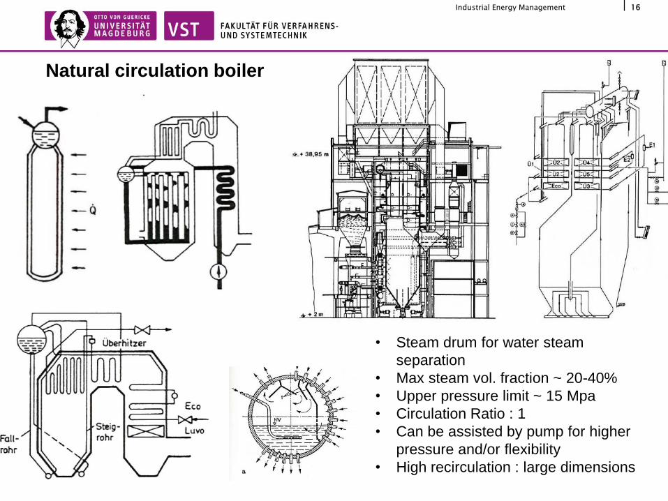
Natural circulation boiler
• Steam drum for water steam
separation
• Max steam vol. fraction ~ 20-40%
• Upper pressure limit ~ 15 Mpa
• Circulation Ratio : 1
• Can be assisted by pump for higher
pressure and/or flexibility
• High recirculation : large dimensions

17Industrial Energy Management
Forced-circulation boilers
Air preheater
Economiser
Drum
Evapo
-rator
Circul-
ation
pumpMud drum
Superheater

18Industrial Energy Management
• No recirculation : higher load
• Can operate at supercritical pressure
• Complex control and no buffer
Once-through boiler
source: H. Effenberger, Dampferzeuger
19Industrial Energy Management
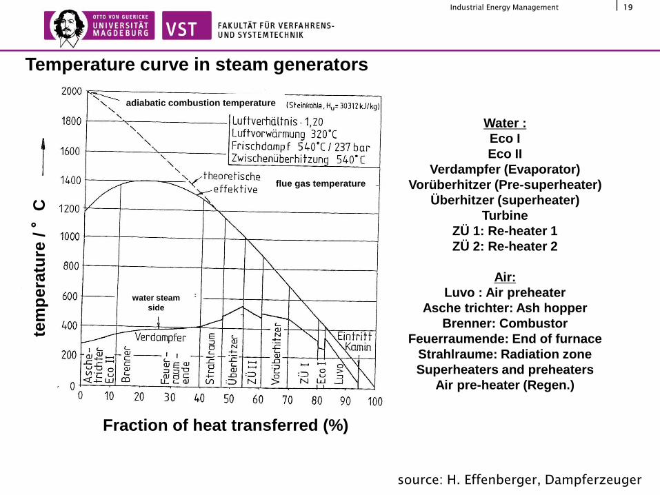
Temperature curve in steam generators
tem
pe
ratu
re/ °
C
Fraction of heat transferred (%)
adiabatic combustion temperature
flue gas temperature
evaporator
rad
iati
on
zo
ne
su
pe
r h
eate
rre
he
ate
rII
pre
su
pe
r h
eate
r
reh
eat.
I
EC
O I
Air
Water :
Eco I
Eco II
Verdampfer (Evaporator)
Vorüberhitzer (Pre-superheater)
Überhitzer (superheater)
Turbine
ZÜ 1: Re-heater 1
ZÜ 2: Re-heater 2
Air:
Luvo : Air preheater
Asche trichter: Ash hopper
Brenner: Combustor
Feuerraumende: End of furnace
Strahlraume: Radiation zone
Superheaters and preheaters
Air pre-heater (Regen.)
water steam
side
source: H. Effenberger, Dampferzeuger
20Industrial Energy Management
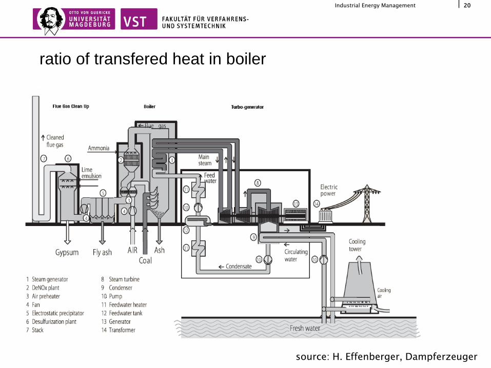
ratio of transfered heat in boiler
evaporation
feedwater preheating
superheating
reheating 2ra
tio
of
heat
/ %
fresh steam pressure / bar
source: H. Effenberger, Dampferzeuger

21Industrial Energy Management
power plant design, air preheating
scheme for regenerative air preheaters with a) rotating heat storage mass and
b) fixed storage mass
rotating storagerotating
air hood
air inflow
air inflow
flue gas flue
gas
source: H. Effenberger, Dampferzeuger

22Industrial Energy Management
Regenerative Air preheater : Static heat storage – Rotating air
hood. Type Rothemühle
Rotation speed : 1 RPM
400m3/s
D=17.5 m
Heat transfer area:
~100000 m2
1. Hot air
2. Cold air
3. Combustion gases entry
4. Combustion gases exit
source: H. Effenberger, Dampferzeuger

23Industrial Energy Management
Regenerative Air preheater : Rotating heat storage mass. Type
Ljungström.
Rotation speed : 1-4 RPM
400m3/s
D=15 m
Heat transfer area: ~24000 m2
1. Cold air
2. Hot air
3. Combustion gases entry
4. Combustion gases exit
source: H. Effenberger, Dampferzeuger

24Industrial Energy Management
• Fly ashes contains variety of toxic inorganic compounds (As, Be, ….) over a
wide size range (10’s nm-100’s microns)
• Electrostatic precipitation to separate particles from flue gases.
Soot removal - Electrostatic precipitator

25Industrial Energy Management
NOx removal – SCR and NSCR

26Industrial Energy Management
• Form CaSO4 from CaCO3 and SO2
Flue Gas Desulphurization

273011.2012ISUT-Seminar Jörg Sauerhering
Thanks for your attention!
sources: H. Effenberger, DampferzeugerK. Kugeler, EnergietechnikT. Bohn, Band 5 Handbuchreihe Energie