industrial background research problematic method overview key characteristics assembly sequence...
Post on 20-Dec-2015
214 views
TRANSCRIPT

Industrial BackgroundResearch ProblematicMethod OverviewKey Characteristics Assembly Sequence Conclusion
AD
CA
TS
Co
nfe
ren
ce -
14/
15 J
un
e 20
01
AD
CA
TS
Co
nfe
ren
ce -
14/
15 J
un
e 20
01
Bri
gh
am Y
ou
ng
Un
iver
sity
- P
rovo
UT
Bri
gh
am Y
ou
ng
Un
iver
sity
- P
rovo
UT
Benoît Marguet E.A.D.S Corporate Research Center - France
Tel : +33-1-46-97-33-46email : [email protected]
Method & Tools for Method & Tools for Geometric Variation ManagementGeometric Variation Management

Industrial Background (I)Industrial Background (I)
Complex Product
Extensive manufacturing organisation
Structural Assembly
High number of parts
Various Assembly levels
Aircraft Assembly Line
Car Assembly Line
Assembly
Conversion
Material
45%45%
30%30%
25%25%
Aircraft manufacturing cost :
}Importance of Assembly Cost
Need to manage product’s assemblability
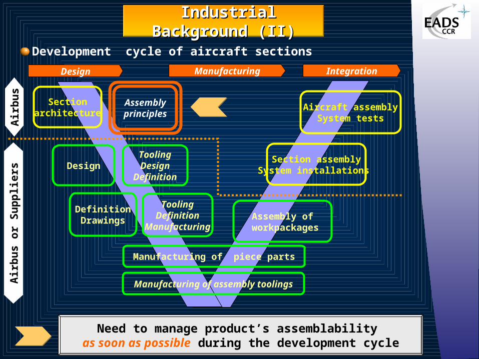
Design Manufacturing Integration
Section assemblySystem installations
Aircraft assemblySystem tests
Sectionarchitecture
DesignToolingDesign
Definition
DefinitionDrawings
ToolingDefinition
Manufacturing
Manufacturing of piece parts
Assembly of workpackages
Manufacturing of assembly toolings
Air
bu
s o
r S
up
plie
rsA
irb
us
Assemblyprinciples
Industrial Background (II)Industrial Background (II)
Development cycle of aircraft sections
Need to manage product’s assemblability as soon as possible during the development cycle

ProblematicProblematic
Sub-section assembly operation
How to improve product’s assemblability ? • By reducing assembly failures
• Parts reduction
• Geometric variation management
Where to manage product variations ?
How to control effect of variations on functional requirements?
Geometric Variation Management Method (GEOVAR)
How to reduce assembly failures ?

Method OverviewMethod Overview
Design Principle
Product Structure
j1
j2 j4
j6
j5j3
j7j8
Key Characteristics
Assembly SequenceManufacturing Capabilities
Part Specifications
GEOVAR : From product’s Key Characteristics to part’s specifications

Product Product Key Characteristics (I)Key Characteristics (I)
Concepts• Functional requirements & related geometrical characteristics
are too numerous on complex product in order to manage all of them.
• Need to focus attention of designers & manufacturers on what is really
important for the product.
Definition “Product Key Characteristics are the geometrical features of component or sub-component whose variation has the greatest influence on the product function”.
Functional Requirement Identification
(1)
Functional Requirement Identification
(1)
Geometrical Requirement
Identification (2)
Geometrical Requirement
Identification (2)
Product Key Characteristics Identification
(3)
Product Key Characteristics Identification
(3)
Identification Process
KC

1
Product Product Key Characteristics (II)Key Characteristics (II)
Functional Requirement Identification
• Inputs : Preliminary Design, Product Structure
• Outputs : Technical Requirements, Product Constraints
• Tools : FAST Diagram, MIMIO
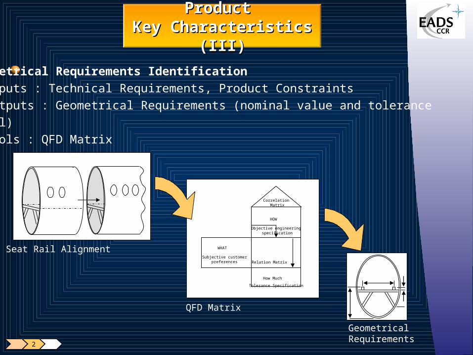
Geometrical Requirements Identification• Inputs : Technical Requirements, Product Constraints • Outputs : Geometrical Requirements (nominal value and tolerance
level)• Tools : QFD Matrix
WHAT
Subjective customerpreferences
HOW
Objective engineering specification
Relation Matrix
How Much
Tolerance Specification
Correlation Matrix
QFD Matrix
Seat Rail Alignment
Geometrical Requirements
2
Product Product Key Characteristics (III)Key Characteristics (III)
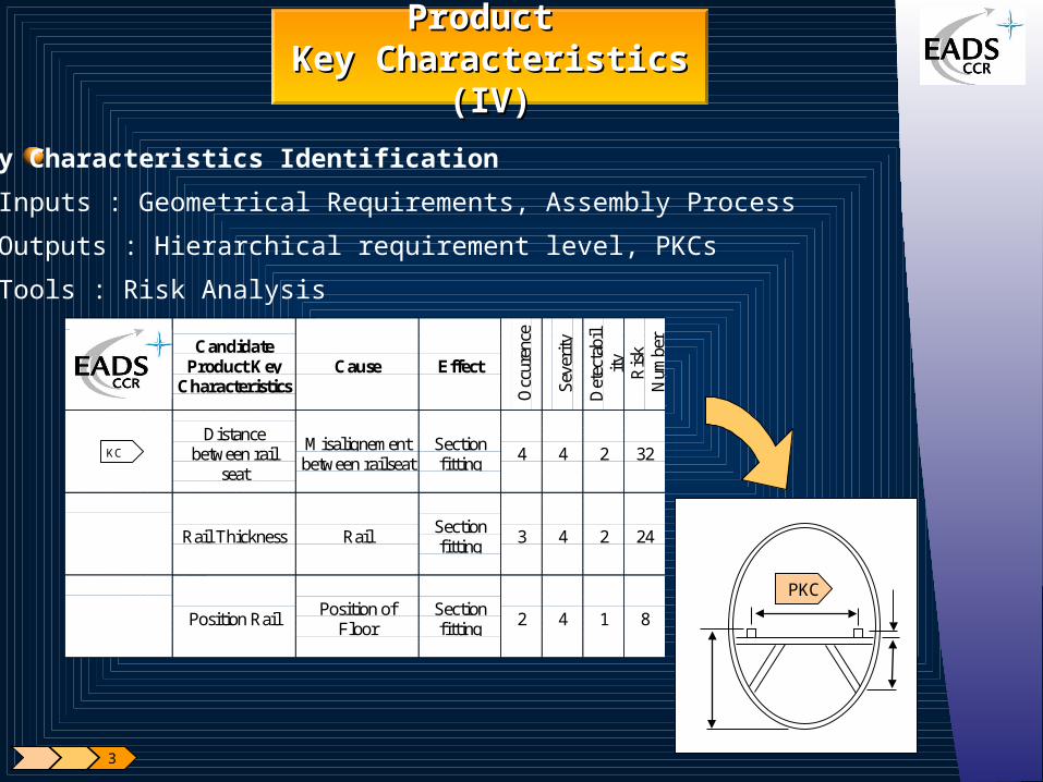
Key Characteristics Identification
• Inputs : Geometrical Requirements, Assembly Process
• Outputs : Hierarchical requirement level, PKCs
• Tools : Risk Analysis
CandidateProduct Key
CharacteristicsCause Effect
Occ
uren
ce
Sev
erit
y
Det
ecta
bil
ity
Ris
kN
umbe
r
Distancebetween rail
seat
Misalignementbetween railseat
Sectionfitting
4 4 2 32
Rail Thickness RailSectionfitting
3 4 2 24
Position RailPosition of
FloorSectionfitting
2 4 1 8
KC
PKC
3
Product Product Key Characteristics (IV)Key Characteristics (IV)
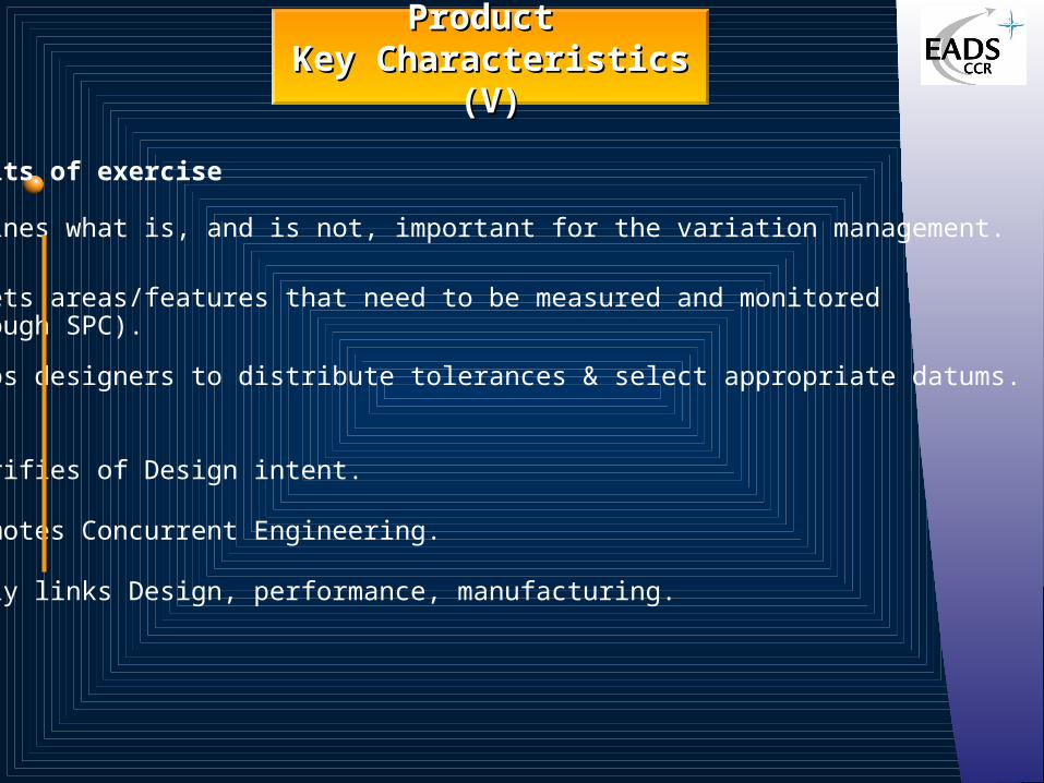
Benefits of exercise • Defines what is, and is not, important for the variation management.
•Targets areas/features that need to be measured and monitored (through SPC).
• Helps designers to distribute tolerances & select appropriate datums.
Also • Clarifies of Design intent.
• Promotes Concurrent Engineering.
• Truly links Design, performance, manufacturing.
Product Product Key Characteristics (V)Key Characteristics (V)
Assembly Sequence (I)Assembly Sequence (I)
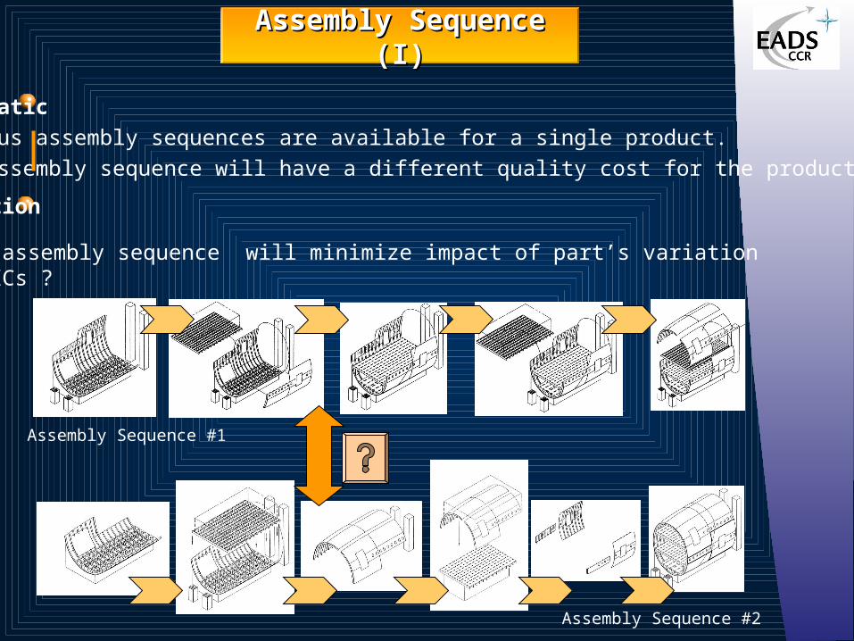
Problematic• Various assembly sequences are available for a single product.• All assembly sequence will have a different quality cost for the product.
Question
What assembly sequence will minimize impact of part’s variation on PKCs ?
Assembly Sequence #1
Assembly Sequence #2

Assembly Sequence (II)Assembly Sequence (II)
Concepts• Assembly Sequence analysis focus on PKCs (for variation impact). • Impact of part variation on PKCs depends on assembly sequence
choice.• Selection of assembly sequence is made very early in the design cycle.
Mate & Contact Identification
(1)
Mate & Contact Identification
(1)
Propagation Chain Identification
(2)
Propagation Chain Identification
(2)
Worst Case &StatisticalTolerance Analysis
(3)
Worst Case &StatisticalTolerance Analysis
(3)
Analysis Process
Goal
To analyze as soon as possible during the design cycle, all admissible
assembly sequences in order to select the optimal one.

Mate & Contact Identification (I)
Definition (D.E Whitney) • A mate is an assembly link that establishes constraints and dimensional
relationships between part.• A contact is an assembly link that supports and fastens the part once it
is located.
Property
Mate and Contact are related to the assembly sequence.
Geometrical variations flow from part to part through mates only.
Benefice• Easy to represent on a graph• Tool for variation propagation
analysis.
Assembly Sequence (III)Assembly Sequence (III)
Stringer
Cleat
Cleat Pannel
M
MM
M
MM
C
C
C
C
Mate
Contact
M
C
1

Assembly Sequence (IV)Assembly Sequence (IV)
Assembly Sequence #1
Lower Floor
Lower Shell
Upper Shell Left
Upper Shell Right
Tool
Door
Upper Floor
Mate & Contact Identification (II)
Tools : Assembly Oriented Graph.
Assembly surfaces
Mate
Contact
PKC1
KC
AOG is a directed acyclic graphical representation of an assembly given a picture of the location dependencies of parts and surfaces. Each node represents assembly surface. Oriented arcs represent mates between two assembly surfaces. The arrow points on the positioned component. Oriented dotted arcs represent contacts between two assembly surfaces and dotted line represents geometrical conditions
Assembly Sequence (V)Assembly Sequence (V)
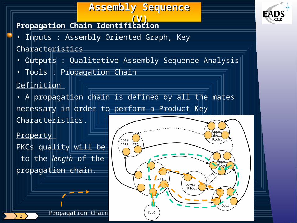
Propagation Chain Identification
• Inputs : Assembly Oriented Graph, Key Characteristics
• Outputs : Qualitative Assembly Sequence Analysis
• Tools : Propagation Chain
Definition
• A propagation chain is defined by all the mates necessary in order to
perform a Product Key Characteristics.
Property
PKCs quality will be related
to the length of the
propagation chain.
Lower Floor
Lower Shell
Upper Shell Left
Upper Shell Right
Tool
Door
Upper Floor
2Propagation Chain
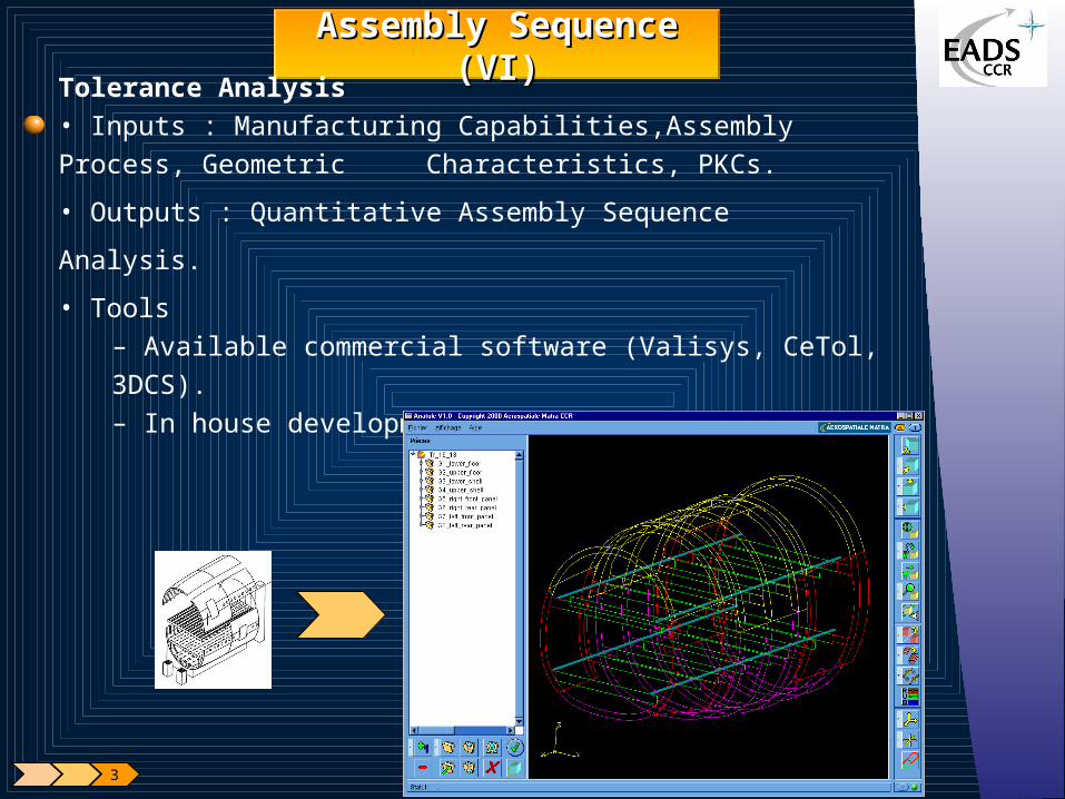
Assembly Sequence (VI)Assembly Sequence (VI)
Tolerance Analysis• Inputs : Manufacturing Capabilities,Assembly Process, Geometric
Characteristics, PKCs.
• Outputs : Quantitative Assembly Sequence Analysis.
• Tools – Available commercial software (Valisys, CeTol, 3DCS).– In house development (AnaTole).
3

Assembly Sequence (VI)Assembly Sequence (VI)
AnaTole Software• In house development based on TTRS, Variation Model (EADS C.C.R) and
Open Cascade (EADS MatraDatavision).
• Benefits :
– Easy to use without a deep knowledge of CAD system.
– Very close to manufacturing and Design process.
– Over-Constraint Detection and Analysis.
– Statistical & Worst Case Tolerance Analysis.
– Useable as soon as possible in the design cycle (wireframe geometry only).
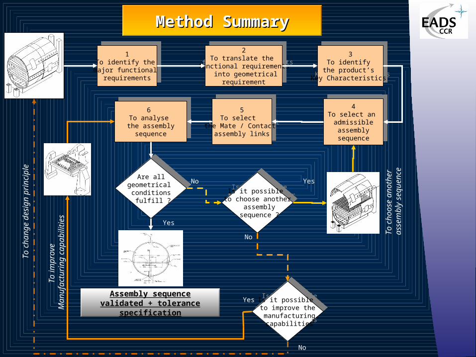
Method SummaryMethod Summary
1To identify the
major functional requirements
1To identify the
major functional requirements
2To translate the
functional requirements into geometrical
requirement
2To translate the
functional requirements into geometrical
requirement
3To identify
the product’s Key Characteristics
3To identify
the product’s Key Characteristics
4To select an admissible assembly sequence
4To select an admissible assembly sequence
Yes
To
ch
oo
se a
no
the
r a
sse
mb
ly s
eq
ue
nce
To
ch
an
ge
de
sig
n p
rinci
ple
5To select
the Mate / Contact assembly links
5To select
the Mate / Contact assembly links
6 To analyse
the assembly sequence
6 To analyse
the assembly sequence
Are allgeometrical conditions
fulfill ?
Are allgeometrical conditions
fulfill ?
Is it possible to choose another
assembly sequence ?
Is it possible to choose another
assembly sequence ?
Is it possible to improve the manufacturing
capabilities
Is it possible to improve the manufacturing
capabilities
To
imp
rove
M
an
ufa
ctu
ring
ca
pa
bili
ties
Assembly sequencevalidated + tolerance specification
Yes
Yes
No
No
No

Conclusion & Future prospectConclusion & Future prospect
Need to manage tolerance from the functional requirement to ISO
specification based on :• Product Key Characteristics• Assembly processes• Manufacturing Capabilities
Definition & Deployment of a Variation Management Method• Useful for complex product like aircraft.• Used as soon as possible during the design process.• Allowing to select the optimal assembly sequence.
On going Works • Take into account flexible parts in the method• Automatic assembly sequence planning
& analysis.• Wide deployment of the method.